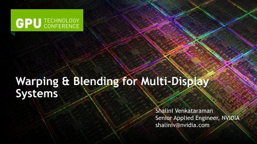
Warping & Blending for Multi-Display Systems - GTC 2012
Warping & Blending for Multi-Display Systems - GTC 2012
Warping & Blending for Multi-Display Systems - GTC 2012

You also want an ePaper? Increase the reach of your titles
YUMPU automatically turns print PDFs into web optimized ePapers that Google loves.
<strong>Warping</strong> & <strong>Blending</strong> <strong>for</strong> <strong>Multi</strong>-<strong>Display</strong><strong>Systems</strong>Shalini VenkataramanSenior Applied Engineer, NVIDIAshaliniv@nvidia.com
Agenda• The problem – what do we mean by seamless?• The way it has been done up till now• Our Solution• Programming <strong>for</strong> <strong>Multi</strong>-display configurations
The Problem• Increases in pixel density and total pixels have not keptpace with increases in CPU and GPU power• Different solutions <strong>for</strong> adding more pixels— LCDs: obtrusive bezels in the way— Nearly bezel-less
The Problem (cont’d)• Projectors: optics (and screens) are never perfect
The Problem (cont’d)• Just creating the overlap makes a hot spot since the overlapregion gets twice the light
The solution• Warp & Blend— Warp = Geometry Corrections— Blend = Intensity corrections• Can do one or the other, or both
The way it’s been done up until now• Hardware appliance <strong>for</strong> warp and intensity adjustment— Expensive— Extra per<strong>for</strong>mance delay tax on the display pipeline— Additional complexity• Software warp and intensity adjustment— Applications need to be written to manage— There has not been an easy way to implement this <strong>for</strong> anyapplication, until now…
NVIDIA’s Solution• We can do this on the GPU!— GPUs are inherently parallel and already have the pixelin<strong>for</strong>mation• Fast <strong>for</strong> image processing operations— GPUs are designed <strong>for</strong> imaging, texturing and raster operations(compared with external boxes using FPGAs)— Per<strong>for</strong>m the trans<strong>for</strong>mation in the display pipeline be<strong>for</strong>e thepixels get scanned out— By doing this on the GPU, we have more flexibility: high qualityfiltering, integration with SLI Mosaic, etc.
NVIDIA’s Solution• Works on Quadro 5000, 6000, and Quadro Plex 7000• Use it with G-sync to get synchronization between displays
How’s it Done: Warp & Blend WorkflowDefine DistortionNumericalOpticalCreate warping meshand texturecoordinates toimplement distortionTypical <strong>Warping</strong>Mesh contains 4-2Mvertices
How’s it Done: Overall Workflow• Set Mosaic Topology• Capture imagery <strong>for</strong> warp & blendcalculation (optical)• Compute and set overlap• For each displayCompute and set warp, intensityand black adjustmentDoug Traill, S0341 - See the Big Picture Scalable Visualization Solutions <strong>for</strong> SystemIntegrators, <strong>GTC</strong> <strong>2012</strong> recordings
How’s it Done Programmatically: NVAPI• NVAPI is Nvidia’s programmatic interface to configure andcontrol the GPUs. http://developer.nvidia.com/nvapi— Query/Set GPU and display configurations, layouts etc• New interfaces are added in the 295+ NDA version to allowwarping and intensity adjustment be<strong>for</strong>e the final scanout• R302 NDA version will add support <strong>for</strong> image offset to doblack-level adjustment• Works on single screen, multiple screens and multi-gpuconfiguration• Win 7 only
Enumerating <strong>Display</strong>s• Get number of gridsNvU32 gridCount;NvAPI_Mosaic_Enum<strong>Display</strong>Grids(NULL, &gridCount)• Get display topologygridTopo = new NV_MOSAIC_GRID_TOPO[gridCount];NvAPI_Mosaic_Enum<strong>Display</strong>Grids(gridTopo, gridCount)gridTopo[0]consolegridTopo[1]1x2 mosaicgridCount = 2
Getting <strong>Display</strong> Topology• Iterate over all grids and displays and get properties<strong>for</strong> (NvU32 iGrid = 0; iGrid < gridCount; iGrid++) {NvU32 num<strong>Display</strong>s = gridTopo[iGrid].displayCount ; //No of displays in this gridNvU32 numRows = gridTopo[iGrid].rows; //No of rows in this gridNvU32 numCols = gridTopo[iGrid].columns; //No of columns in this gridNV_MOSAIC_DISPLAY_SETTING& ds = gridTopo[iGrid].displaySettings;ds.width; ds.height; ds.freq ; //Width, Heiht and Refresh Rate <strong>for</strong> all displays<strong>for</strong> (NvU32 i<strong>Display</strong>=0; i<strong>Display</strong>< gridTopo[iGrid].displayCount ;i<strong>Display</strong>++) {NV_MOSAIC_GRID_TOPO_DISPLAY& display = gridTopo[iGrid].displays[i<strong>Display</strong>];NvU32 displayId = display.displayId ;//unique identifier <strong>for</strong> this display, that// will be used <strong>for</strong> all subsequent functionsdisplay.overlapX; //horizontal overlap <strong>for</strong> this display, explained laterdisplay.overlapY; //vertical overlap <strong>for</strong> this display, explained later}}1x2 mosaicconsoledisplayId[0,0]gridTopo[0]displayCount=11x1displayId[1,0]displayId[1,1]gridTopo[1]displayCount = 21x2
overlapYProgramming overlap per grid• Specifying overlapX and overlapY— the number of pixels of overlap between each display and theprevious row or column— All displays in a column (row) should have same overlapX (overlapY)NV_MOSAIC_GRID_TOPO& grid = gridTopo[1];//column 0: set overlapX =0grid.display[0].overlapX = 0;grid.display[2].overlapX = 0;//row 0: set overlapY =0grid.display[0].overlapY = 0;grid.display[1].overlapY = 0;//column 1: 200px overlap between column 0 & 1grid.displays[1].overlapX = 100;grid.displays[3].overlapX = 100;//row 1: 100px overlap between row 0 & 1grid.displays[2].overlapY = 100;grid.displays[3].overlapY = 100;displays[0] 200100displays[2]overlapX200displays[1]2x2 mosaic100displays[3]
Overlap cont’d• <strong>Display</strong>s in different rows/columns can have different overlaps[0,0] [0,1]grid.display[0].overlapX = 0;grid.display[1].overlapX = 100;grid.display[2].overlapX = 200;01grid.display[3].overlapX = 50; 100 200 px 50[0,2] [0,3]2 3• Set <strong>for</strong> entire grid topology1x4 mosaicNvAPI_Status ret = NvAPI_Mosaic_Set<strong>Display</strong>Grids(gridTopo, gridCount,NV_MOSAIC_SETDISPLAYTOPO_FLAG_CURRENT_GPU_TOPOLOGY);Check return value and handle errors properly!
Fun with display coordinate systems• scanoutRect— Per display• desktopRect— Subregion relative to desktop— Includes overlap• osRect— Extent of OS-visible virtualdesktop• eg .\\<strong>Display</strong>1— Includes overlap.\\<strong>Display</strong>1osRect3640(0,0)displayID 0desktopRect1920(1720,0)(0,0)1920scanoutRect200pxdisplayID 1120012001200
Getting display coords from NVAPI• For each display, get its scanoutRect and desktopRectNvSBox desktopRect; //extent of this display wrt desktopNvSBox scanoutRect; //extent per displayNvAPI_GPU_GetScanoutConfiguration(displayId, &desktopRect, &scanoutRect);• For each display, get its osRectNvSBox osRect; //os coordinates <strong>for</strong> this virtual displayDEVMODEA dm = { 0 };dm.dmSize = sizeof(DEVMODEA);if (Enum<strong>Display</strong>SettingsA(displayName, ENUM_CURRENT_SETTINGS, &dm)) {osRect.sX = dm.dmPosition.x;osRect.sY = dm.dmPosition.y;osRect.sWidth = dm.dmPelsWidth;osRect.sHeight = dm.dmPelsHeight;}
Warp example12001920(480,0)(1920,0)V0V2Vertex positions specified in scanoutRect spacePositionsV1V3(0,1200) (1440,1200)displayID 1displayID 0displayID 1displayID 0 V1 displayID 1 V3 Texture coords specified from desktopRect3640(1720,0) (3640,0)V0V2TextureCoords(1720,1200)(3640,1200)
<strong>Warping</strong> Data Structure• NV_SCANOUT_WARPING_DATA— vertexFormat : strip or triangle list• NV_GPU_WARPING_VERTICE_FORMAT_TRIANGLESTRIP_XYUVRQ• NV_GPU_WARPING_VERTICE_FORMAT_TRIANGLES_XYUVRQ— vertices : array of 6 float vertex• x,y : mesh coordinates per-display rectangle• u,v : texture coordinates in desktop space• r,q : perspective mapping to simulate 3D warp— numVertices— textureRectu,v onlyu,v,r,q• Pass in the osRect
<strong>Warping</strong> - Code• Enable <strong>Warping</strong>float vertices[numVerts*6] ={x0,y0,u0,v0,r,q, x1,y1,u1,v1,r,q, …};NV_SCANOUT_WARPING_DATA warpingData;warpingData.version = NV_SCANOUT_WARPING_DATA_VER;warpingData.numVertices = numVerts;warpingData.vertexFormat =NV_GPU_WARPING_VERTICE_FORMAT_TRIANGLESTRIP_XYUVRQ;warpingData.vertices = vertices;warpingData.textureRect = osRect;int sticky = 0; // output - Reserved field <strong>for</strong> future useint maxNumVertices = 0; // output – returns the #pixels at scanout// This call does the warpNvAPI_Error error = NvAPI_GPU_SetScanout<strong>Warping</strong>(displayId, &warpingData,&maxNumVertices, &sticky);• Disable <strong>Warping</strong>warpingData.numVertices = 0;warpingData.vertices = NULL;NvAPI_GPU_SetScanout<strong>Warping</strong>(displayId,…);
Blend ExampleScanout ImageOverlapregion<strong>Blending</strong> Texture1.0 0.5 1.0FinalOutput Image
Blend – with Offset Texture• New feature starting R302• Separate offset texture— Inverse of black-level image— Can be 1 or 3 channel— Blended with already modulated imageEntire surface needsto be this brightOutput= Input ∗ blendTexture ∗ 1 − offsetTexture + offsetTexture
Blend/Intensity Adjustment• NV_SCANOUT_INTENSITY_DATA— width, height• Dimensions of blending texture• Normally same dimensions as scanout rectangle• If larger than scanout size, driver dynamically downsamples using box filter— blendingTexture• float[width*height*3], RGB with same storage layout as OpenGL• Set to NULL <strong>for</strong> no adjusments— offsetTexture• Same dimensions as blendingTexture— offsetTexChannels• Number of components in the offsetTexture, 1 or 3
<strong>Blending</strong> - CodeNV_SCANOUT_INTENSITY_DATA intensityData;// simple 1x2 config, overlap region is modulated by 0.5float intensityTexture[6] = {0.5f, 0.5f, 0.5f,1.0f, 1.0f, 1.0f} ;// overlapped region doesn’t require an offsetfloat offsetTexture[6] = {0.0f, 0.0f, 0.0f,0.1f, 0.1f, 0.1f} ;intensityData.version= NV_SCANOUT_INTENSITY_DATA_VER;intensityData.width = 2;intensityData.height = 1;intensityData.blendingTexture = intensityTexture;intensityData.offsetTexture = offsetTexture;intensityData.offsetTexChannels = 3;int sticky = 0; // output - Reserved field <strong>for</strong> future use// This call does the intensity mapNvAPI_Status error = NvAPI_GPU_SetScanoutIntensity(displayId,&intensityData, &sticky);
Pointers• Disabling/enabling warp is expensive— Requires modeset, lag in projector environments— However, changing the warp mesh does not require modeset• Eg During calibration, use identity quad with warp call to simulate no warping• Changing warp mesh is not deterministic— Warp should not be changed <strong>for</strong> continuous updates• Eg eye tracking at 60Hz, best to do that in the app— OK to change it infrequently• Eg during calibration
Feature Roadmap• Filtering— Other options• Offset Image addition— Various blending modes• Persistence across reboot— making the settings consistent acrossreboots• Linux support
Questions?quadrosvs@nvidia.com