232BRC - Manual - RS-232 Baud Rate Converter - Delmation
232BRC - Manual - RS-232 Baud Rate Converter - Delmation
232BRC - Manual - RS-232 Baud Rate Converter - Delmation

You also want an ePaper? Increase the reach of your titles
YUMPU automatically turns print PDFs into web optimized ePapers that Google loves.
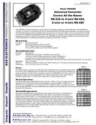
<strong>RS</strong>-<strong>232</strong> <strong>Baud</strong> <strong>Rate</strong> <strong>Converter</strong> CEModel <strong><strong>232</strong>BRC</strong>Documentation Number <strong><strong>232</strong>BRC</strong>-3903 (pn5104-r003)International HeadquartersB&B Electronics Mfg. Co. Inc.707 Dayton Road -- P.O. Box 1040 -- Ottawa, IL 61350 USAPhone (815) 433-5100 -- General Fax (815) 433-5105Home Page: www.bb-elec.comSales e-mail: orders@bb-elec.com -- Fax (815) 433-5109Technical Support e-mail: support@bb-elec.com -- Fax (815) 433-5104European HeadquartersB&B Electronics Ltd.Westlink Commercial Park, Oranmore, Co. Galway, IrelandPhone +353 91 792444 -- Fax +353 91 792445Home Page: www.bb-europe.comSales e-mail: orders@bb-europe.comTechnical Support e-mail: support@bb-europe.com© B&B Electronics – Revised October 2003<strong><strong>232</strong>BRC</strong>-3903 <strong>Manual</strong> Cover PageB&B Electronics Mfg Co Inc – 707 Dayton Rd - PO Box 1040 - Ottawa IL 61350 - Ph 815-433-5100 - Fax 815-433-5104B&B Electronics Ltd – Westlink Commercial Park – Oranmore, Galway, Ireland – Ph +353 91 792444 – Fax +353 91 792445
TABLE OF CONTENTSChapter 1: INTRODUCTION.............................................. 3Applications ........................................................................... 3Specifications ........................................................................ 4Default Parameters ............................................................... 4Checklist................................................................................ 5Chapter 2: OPERATION ..................................................... 7Port Configurations................................................................ 7Port Connections................................................................... 9LED Indicators..................................................................... 11Chapter 3: SETUP SOFTWARE...................................... 13Introduction.......................................................................... 13Connection .......................................................................... 13Software Installation ............................................................ 14Software Uninstall ............................................................... 14Setup Tutorial ...................................................................... 15Main Screen ........................................................................ 15Copying Parameters Between Units ................................... 16Final System Installation ..................................................... 17Default Parameters ............................................................. 17Appendix A: Cable Charts............................................. A-1Port A Connections ............................................................A-1Chart A.1. DTE (PC) DB9 to Port A (DCE) ........................A-1Chart A.2. DTE (PC) DB25 to Port A (DCE) ......................A-1Chart A.3. DCE (Modem) DB9 to Port A (DCE).................A-2Chart A.4. DCE (Modem) DB25 to Port A (DCE)...............A-2Port B Connections ............................................................A-2Chart A.5. DCE (Modem) DB9 to Port B (DTE) .................A-2Chart A.6. DCE (Modem) DB25 to Port B (DTE) ...............A-3Chart A.7. DTE (PC) DB9 to Port B (DTE).........................A-3Chart A.8. DTE (PC) DB25 to Port B (DTE).......................A-3Appendix B: Block Diagram.......................................... B-1Appendix C: Declaration of Conformity....................... C-1<strong><strong>232</strong>BRC</strong>-3903 <strong>Manual</strong> Table of Contents iB&B Electronics Mfg Co Inc – 707 Dayton Rd - PO Box 1040 - Ottawa IL 61350 - Ph 815-433-5100 - Fax 815-433-5104B&B Electronics Ltd – Westlink Commercial Park – Oranmore, Galway, Ireland – Ph +353 91 792444 – Fax +353 91 792445ii Table of Contents <strong><strong>232</strong>BRC</strong>-3903 <strong>Manual</strong>B&B Electronics Mfg Co Inc – 707 Dayton Rd - PO Box 1040 - Ottawa IL 61350 - Ph 815-433-5100 - Fax 815-433-5104B&B Electronics Ltd – Westlink Commercial Park – Oranmore, Galway, Ireland – Ph +353 91 792444 – Fax +353 91 792445
Chapter 1: INTRODUCTIONThe <strong><strong>232</strong>BRC</strong> acts as a translator between devices withincompatible asynchronous serial communications. Each port uses adedicated UART and includes a 16 kbyte receive buffer. Each portcan be independently configured for data rate, data format, andhandshaking.Each side of the <strong><strong>232</strong>BRC</strong> can be configured to match theconnected device. It supports any data rate up to 115.2 kbps and allstandard data formats. Each side can either supply or accepthardware or software handshaking. Setup parameters areconfigured through the PC setup software provided and saved innon-volatile memory.The <strong><strong>232</strong>BRC</strong> is supplied with two DB9 connectors. The femaleconnector is configured as a DCE for connecting to PCs, Terminals,and other DTE devices. The male connector is configured as a DTEfor connecting to Modems and other DCE devices. Three LEDsindicate power and the presence of data in either port’s buffer.Applications• Connect devices with different data rates.• Convert from hardware to software handshaking.• Convert between data formats.• Add handshaking to a streaming device.• Use as a port buffer to increase throughput.SpecificationsModel: <strong><strong>232</strong>BRC</strong>Interface: <strong>RS</strong>-<strong>232</strong> AsynchronousData Bits: 5, 6, 7, or 8Parity: Even, Odd, or NoneData <strong>Rate</strong>: 300 to 115.2 kbpsStop Bits: 1 or 2Flow Control: Hardware(RTS/CTS),Software(XON/XOFF), or NoneBuffer Memory: 16 Kbytes SRAM per portLEDs: Buffer A, Buffer B, PowerPower Requirements: +12 to +17 VDC @ 60mA max.Power Connector: 2.5mm Phono Jack (+ Tip)Recommended Supply: B&B Model <strong>232</strong>PSData Connectors: Port A DB9 FemalePort B DB9 MaleDimensions:5.8 x 3.6 x 1.2 in. (14.6 x 9.1 x 3.0 cm)Setup Software: PC compatible, Windows 95/98/NT/2000Supplied Accessories: (2) 3.5” Floppy DiskettesInstruction <strong>Manual</strong>Default ParametersWhen shipped, the <strong><strong>232</strong>BRC</strong> comes set up for the followingparameters for ports A and B:Data <strong>Rate</strong> = 9600 bpsData Bits = 8Stop Bits = 1Parity = NoneHandshaking = NoneRefer to the following sections of the manual for what each ofthese parameters means and how they can be changed.<strong><strong>232</strong>BRC</strong>-3903 <strong>Manual</strong> 3B&B Electronics Mfg Co Inc – 707 Dayton Rd - PO Box 1040 - Ottawa IL 61350 - Ph 815-433-5100 - Fax 815-433-5104B&B Electronics Ltd – Westlink Commercial Park – Oranmore, Galway, Ireland – Ph +353 91 792444 – Fax +353 91 7924454<strong><strong>232</strong>BRC</strong>-3903 <strong>Manual</strong>B&B Electronics Mfg Co Inc – 707 Dayton Rd - PO Box 1040 - Ottawa IL 61350 - Ph 815-433-5100 - Fax 815-433-5104B&B Electronics Ltd – Westlink Commercial Park – Oranmore, Galway, Ireland – Ph +353 91 792444 – Fax +353 91 792445
ChecklistExamine the shipping carton and contents for physical damage.If damage is found, file a claim with the shipper immediately.The following equipment should be in the shipping carton:1. <strong>RS</strong>-<strong>232</strong> <strong>Baud</strong> <strong>Rate</strong> <strong>Converter</strong> model <strong><strong>232</strong>BRC</strong>2. Instruction <strong>Manual</strong>3. (2) 3.5" floppy disksIf any of the items above are not in the shipping carton contactthe shipper immediately.<strong><strong>232</strong>BRC</strong>-3903 <strong>Manual</strong> 5B&B Electronics Mfg Co Inc – 707 Dayton Rd - PO Box 1040 - Ottawa IL 61350 - Ph 815-433-5100 - Fax 815-433-5104B&B Electronics Ltd – Westlink Commercial Park – Oranmore, Galway, Ireland – Ph +353 91 792444 – Fax +353 91 7924456<strong><strong>232</strong>BRC</strong>-3903 <strong>Manual</strong>B&B Electronics Mfg Co Inc – 707 Dayton Rd - PO Box 1040 - Ottawa IL 61350 - Ph 815-433-5100 - Fax 815-433-5104B&B Electronics Ltd – Westlink Commercial Park – Oranmore, Galway, Ireland – Ph +353 91 792444 – Fax +353 91 792445
Chapter 2: OPERATIONEach port receives data from its connected device, buffers thedata, and sends it out the opposite port when that port’shandshaking indicates it is ready to receive data. Each port is set tomatch the requirements of its connected device through the setupsoftware.Unused output handshake lines are held high by the <strong><strong>232</strong>BRC</strong>.Pin 6 (DSR) on Port A and Pin 4 (DTR) on Port B are held in aconstant true state. This provides a constant enabled signal toconnected devices that need it, or provides a positive voltage todevices that derive their power from these lines.Port ConfigurationsThe <strong><strong>232</strong>BRC</strong> provides a dedicated UART to ports A and B. Thisallows each port to be individually configured for baud rate, numberof data bits, parity, and hardware (RTS/CTS) or software(XON/XOFF) handshaking. Configuration parameters are setthrough the setup software.<strong>Baud</strong> rate:Each port supports the following standard baud rates:300600120024004800960019.2k38.4k57.6kor 115.2 kbpsIn addition, non-standard baud rates between 300 and 115.2kbps can also be set. The <strong><strong>232</strong>BRC</strong> uses a 1.152 MHz clock for itsbase data rate, so any rate that can be evenly divided into 1.152MHz can be set exactly.For example:28.8 kbps = 1.152 MHz / 40<strong>Baud</strong> rates that are not evenly divisible into 1.152 MHz canalso be used, but the actual baud rate will vary slightly from therequested rate. This may or may not cause data errors, dependingon the attached equipment. Most standard UARTs can accept a 5%to 10% difference in baud rate before errors occur.For example:Desired <strong>Baud</strong> <strong>Rate</strong> = 20 kbps1.152 MHz / 20 kbps = 57.6Actual <strong>Rate</strong> = 1.152 MHz / 58 = 19.862 kbps%error = (20 kbps – 19.862 kbps) / 20 kbps * 100%error = 0.7%Data bits:Each port can be configured for Five, Six, Seven or Eight databits. NOTE: If the ports are set up differently, the port set for fewerdata bits cannot transmit the upper most significant bits.Parity:Each port can be configured for Even, Odd, or No parity. Theparity should be selected to match the connected device.Stop Bits:Each port can be configured for one or two stop bits. The stopbits should be selected to match the connected device.Flow Control:Hardware(RTS/CTS) Handshaking:Each port can be independently configured to hold data untilits input handshake line goes high. On Port A, pin seven (RTS)would have to be held high by the connected device in order for the<strong><strong>232</strong>BRC</strong> to send data. On Port B, pin eight (CTS) needs to be heldhigh by the connected device for the <strong><strong>232</strong>BRC</strong> to send data.Connected devices can prevent data from being sent from the<strong><strong>232</strong>BRC</strong> by holding their corresponding handshake lines low. Thiscorresponds to pin seven on Port A and pin eight on Port B. SeeAppendix A for a complete table of signal directions.<strong><strong>232</strong>BRC</strong>-3903 <strong>Manual</strong> 7B&B Electronics Mfg Co Inc – 707 Dayton Rd - PO Box 1040 - Ottawa IL 61350 - Ph 815-433-5100 - Fax 815-433-5104B&B Electronics Ltd – Westlink Commercial Park – Oranmore, Galway, Ireland – Ph +353 91 792444 – Fax +353 91 7924458<strong><strong>232</strong>BRC</strong>-3903 <strong>Manual</strong>B&B Electronics Mfg Co Inc – 707 Dayton Rd - PO Box 1040 - Ottawa IL 61350 - Ph 815-433-5100 - Fax 815-433-5104B&B Electronics Ltd – Westlink Commercial Park – Oranmore, Galway, Ireland – Ph +353 91 792444 – Fax +353 91 792445
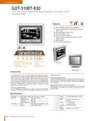
Software(XON/XOFF) Handshaking:Each port can be independently configured for softwarehandshaking. Software handshaking is normally used incommunications links where the main data stream is one way, suchas to a printer. The main sending device is expected to hold off itsdata when it receives the XOFF(13 Hex) character, and resumesending when it receives an XON(11 Hex). The main receivingdevice is expected to send the XOFF character if the buffer is full orit otherwise needs to hold off the data.The <strong><strong>232</strong>BRC</strong> can be set to emulate either the main sendingdevice or the receiving device. It can either supply the XON/XOFFhandshake or stop sending data with the XON/XOFF. The portwould normally be set to supply the XON/XOFF characters if it isconnected to a fast sending device. It would be set to receive theXON/XOFF handshaking if the port is connected to the slowerreceiving device.Port ConnectionsIn order to determine the proper port connections to the<strong><strong>232</strong>BRC</strong>, it is necessary to have a basic understanding of the termsDCE and DTE. <strong>RS</strong>-<strong>232</strong> was designed, using DB-25 connectors, forconnecting a DTE (Data Terminal Equipment) device to a DCE(Data Communication Equipment) device. Each device will haveinputs on pins that correspond to outputs on the same pins of theother device. For example, a DTE device will transmit data out onpin 2 (on a DB-25) and a DCE device will receive data in on pin 2(on a DB-25). IBM PCs and serial printers are DTE devices,modems are DCE devices.Originally the <strong>RS</strong>-<strong>232</strong> Standard specified only a 25 pin, D-subconnector. Since then, the use of a 9 pin, D-sub supporting only aportion of the original <strong>RS</strong>-<strong>232</strong> signals has been used extensively,starting with the IBM PC and migrating into other peripherals. Thepin outs for this 9 pin connector have since become the EIA/TIA 574Standard. This standard specifies a DTE device that transmits onpin 3 and receives on pin 2, with the DCE having the oppositeconfiguration. Figure 2.1 shows the signal direction for 25 pin and 9pin devices configured as a DTE and DCE.25 Pin DTETTTRRRR2 (TD)3 (RD)4 (RTS)5 (CTS)20 (DTR)6 (DSR)8 (DCD)7 (GND)9 Pin DTETTTRRRR3 (TD)2 (RD)7 (RTS)8 (CTS)4 (DTR)6 (DSR)1 (DCD)5 (GND)T = <strong>RS</strong>-<strong>232</strong> Transmitter25 Pin DCE2 (TD)3 (RD)4 (RTS)5 (CTS)20 (DTR)6 (DSR)8 (DCD)7 (GND)Figure 2.1. DTE/DCE Port Diagrams9 Pin DCE3 (TD)2 (RD)7 (RTS)8 (CTS)4 (DTR)6 (DSR)1 (DCD)5 (GND)Port A ConnectionsPort A of the <strong><strong>232</strong>BRC</strong> is a 9 pin, female D-sub connectorconfigured as a DCE. This provides direct connection to an IBM PCcompatible or other DTE device. If it is necessary to connect Port Ato a modem or other device configured as a DCE, a null modemadapter or cable is needed.See Appendix A for a complete set of connection tables to the<strong><strong>232</strong>BRC</strong> ports.Port B ConnectionsPort B of the <strong><strong>232</strong>BRC</strong> is a 9 pin male D-sub connector configuredas a DTE. This provides direct connection to a modem or other DCEdevice. If it is necessary to connect Port B to a PC or other deviceconfigured as a DTE, a null modem adapter or cable is needed.See Appendix A for a complete set of connection tables to the<strong><strong>232</strong>BRC</strong> ports.Power ConnectionsPower to the <strong><strong>232</strong>BRC</strong> is supplied through the 2.5mm Phono jackon the side of the unit (Tip Positive). The <strong><strong>232</strong>BRC</strong> has an integratedregulator, allowing it to operate on any supply voltage between +12to +17 VDC. The <strong><strong>232</strong>BRC</strong> will draw 60 mA max.TTTTRRRR = <strong>RS</strong>-<strong>232</strong> ReceiverTTTTRRR<strong><strong>232</strong>BRC</strong>-3903 <strong>Manual</strong> 9B&B Electronics Mfg Co Inc – 707 Dayton Rd - PO Box 1040 - Ottawa IL 61350 - Ph 815-433-5100 - Fax 815-433-5104B&B Electronics Ltd – Westlink Commercial Park – Oranmore, Galway, Ireland – Ph +353 91 792444 – Fax +353 91 79244510<strong><strong>232</strong>BRC</strong>-3903 <strong>Manual</strong>B&B Electronics Mfg Co Inc – 707 Dayton Rd - PO Box 1040 - Ottawa IL 61350 - Ph 815-433-5100 - Fax 815-433-5104B&B Electronics Ltd – Westlink Commercial Park – Oranmore, Galway, Ireland – Ph +353 91 792444 – Fax +353 91 792445
LED IndicatorsThe <strong><strong>232</strong>BRC</strong> has three LED indicators. The first, labeled“POWER” indicates that power is applied to the converter. The othertwo, labeled “PORT A BUFFER” and “PORT B BUFFER” indicatethat data is present in that port’s receive buffer. Note that the bufferLEDs indicate buffered data only. If either device is fast enough toreceive the data as fast as it can be sent, no data will be buffered,so the LED may not be lit.<strong><strong>232</strong>BRC</strong>-3903 <strong>Manual</strong> 11B&B Electronics Mfg Co Inc – 707 Dayton Rd - PO Box 1040 - Ottawa IL 61350 - Ph 815-433-5100 - Fax 815-433-5104B&B Electronics Ltd – Westlink Commercial Park – Oranmore, Galway, Ireland – Ph +353 91 792444 – Fax +353 91 79244512<strong><strong>232</strong>BRC</strong>-3903 <strong>Manual</strong>B&B Electronics Mfg Co Inc – 707 Dayton Rd - PO Box 1040 - Ottawa IL 61350 - Ph 815-433-5100 - Fax 815-433-5104B&B Electronics Ltd – Westlink Commercial Park – Oranmore, Galway, Ireland – Ph +353 91 792444 – Fax +353 91 792445
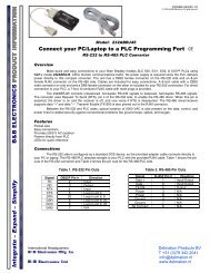
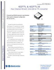
Chapter 3: SETUP SOFTWAREIntroductionThe <strong><strong>232</strong>BRC</strong> comes with simple setup software for configuringthe A and B ports. The software can run on any PC compatiblecomputer using Microsoft Windows 95, 98, NT, or 2000 operatingsystem.Once the ports are configured, all parameters are saved in nonvolatilememory so the <strong><strong>232</strong>BRC</strong> can be powered down and usedanywhere without the loss of configuration data. Configurations canalso be saved to a file for setting up more than one <strong><strong>232</strong>BRC</strong> to thesame configuration.ConnectionA serial (COM) port of the computer should be connected to PortA of the <strong><strong>232</strong>BRC</strong>. If the computer’s serial port is a 9 pin D-sub, astraight through connection cable is required. If the computer’s serialport is a 25 pin D-sub, the cable should be an XT to AT adaptercable such as B&B’s model <strong>232</strong>CAMR, or a cable that wouldnormally be used with a modem. See Appendix A for a complete setof connection tables to the <strong><strong>232</strong>BRC</strong> ports.Remove the screws (4) on the bottom of the <strong><strong>232</strong>BRC</strong> with aPhillips screwdriver. Remove the top cover. Install the setup jumpermarked JP1. See Figure 3.1 diagram of the PCBD. Power up the<strong><strong>232</strong>BRC</strong> with the setup jumper installed to put the unit in setupmode. NOTE: The setup software cannot recognize theconnected unit if the setup jumper is not installed or if thejumper is installed after the <strong><strong>232</strong>BRC</strong> is powered up.Software InstallationThe setup software for the <strong><strong>232</strong>BRC</strong> must be installed on yourhard drive before it can be run. All directions assume the 3.5” floppydrive is assigned to drive A. If your drive is assigned another drivename, replace that name for A in the instructions. To install on yourhard drive follow these steps:• Place the <strong><strong>232</strong>BRC</strong> setup disk #1 in floppy drive A.• Select RUN from the Windows START menu.• Type A:\SETUP and click OKAY.• Follow the instructions in the Installation program.Software UninstallTo remove the <strong><strong>232</strong>BRC</strong> setup software, follow these steps:• Select SETTINGS, CONTROL PANEL from the WindowsSTART menu.• Double Click ADD/REMOVE PROGRAMS• Select <strong><strong>232</strong>BRC</strong> SETUP from the list of installed programs.• Click the ADD/REMOVE button to remove the softwarecomponents.Figure 3.1 Setup Jumper Location<strong><strong>232</strong>BRC</strong>-3903 <strong>Manual</strong> 13B&B Electronics Mfg Co Inc – 707 Dayton Rd - PO Box 1040 - Ottawa IL 61350 - Ph 815-433-5100 - Fax 815-433-5104B&B Electronics Ltd – Westlink Commercial Park – Oranmore, Galway, Ireland – Ph +353 91 792444 – Fax +353 91 79244514 2<strong><strong>232</strong>BRC</strong>-3903<strong>Manual</strong>B&B Electronics Mfg Co Inc – 707 Dayton Rd - PO Box 1040 - Ottawa IL 61350 - Ph 815-433-5100 - Fax 815-433-5104B&B Electronics Ltd – Westlink Commercial Park – Oranmore, Galway, Ireland – Ph +353 91 792444 – Fax +353 91 792445
Step 4: Connect the <strong><strong>232</strong>BRC</strong> to be copied to the serial (COM)port of the PC. Install the setup jumper. Apply power to the<strong><strong>232</strong>BRC</strong>.Step 5: Click Next.Step 6: Select Save As from the File menu. Save theconfiguration to disk.Step 7: Disconnect the first <strong><strong>232</strong>BRC</strong> from the COM port.Step 8: Connect the destination <strong><strong>232</strong>BRC</strong> to the serial (COM) portof the PC. Install the setup jumper. Apply power to the<strong><strong>232</strong>BRC</strong>.Step 9: Select File/Load File and load the saved configuration.Step 10: Click Configure <strong><strong>232</strong>BRC</strong>Once the configuration file has been loaded, any number of <strong><strong>232</strong>BRC</strong>modules can be set to the same parameters by connecting andconfiguring each in turn.Final System InstallationAfter successfully completing and testing the <strong><strong>232</strong>BRC</strong>configuration, remove the setup jumper. Place the unit back in theenclosure and re-insert the 4 Phillips screws.NOTE: The <strong><strong>232</strong>BRC</strong> will not function properly until the setupjumper is removed.Default ParametersWhen shipped, the <strong><strong>232</strong>BRC</strong> comes set up for the followingparameters for ports A and B:Data <strong>Rate</strong> = 9600 bpsData Bits = 8Stop Bits = 1Parity = NoneHandshaking = None<strong><strong>232</strong>BRC</strong>-3903 <strong>Manual</strong> 17B&B Electronics Mfg Co Inc – 707 Dayton Rd - PO Box 1040 - Ottawa IL 61350 - Ph 815-433-5100 - Fax 815-433-5104B&B Electronics Ltd – Westlink Commercial Park – Oranmore, Galway, Ireland – Ph +353 91 792444 – Fax +353 91 79244518 2<strong><strong>232</strong>BRC</strong>-3903<strong>Manual</strong>B&B Electronics Mfg Co Inc – 707 Dayton Rd - PO Box 1040 - Ottawa IL 61350 - Ph 815-433-5100 - Fax 815-433-5104B&B Electronics Ltd – Westlink Commercial Park – Oranmore, Galway, Ireland – Ph +353 91 792444 – Fax +353 91 792445
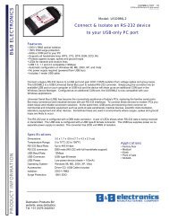
Appendix A: Cable ChartsAll charts give full pinouts. Only pins 2 & 3 are required for basicoperation. Pins 7 and 8 are needed for hardware (RTS/CTS)handshaking. If the connected device requires DTR or DSR, thesesignals are available on pins 4 and 6 respectively. See Appendix Bfor a block diagram of the <strong><strong>232</strong>BRC</strong>.Port A ConnectionsChart A.1. DTE (PC) DB9 Connector to Port A (DCE)DTE (PC)Serial PortDB9 Connector<strong><strong>232</strong>BRC</strong>Port A (DCE)DB9F ConnectorSignalDirection2 3 (TD)4 -----------> 4 (DTR)5 5 (GND)6 7 (RTS)8 3 (TD)3 7 (RTS)5 3 (TD)3 4 (DTR)7 5 (GND)20 2 (RD)3
Chart A.6. DCE (Modem) DB25 Connector to Port B (DTE)DCE (Modem)Serial PortDB25 Connector<strong><strong>232</strong>BRC</strong>Port B (DTE)DB9M ConnectorSignalDirection2 2 (RD)4 8 (CTS)6 ----------> 6 (DSR)7 5 (GND)20 6 (DSR)5 5 (GND)6 8 (CTS)8 2 (RD)3 8 (CTS)5
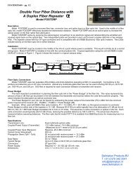
Appendix B: Block DiagramEEPROMMicrocontroller32K SRAMUARTUARTTDRDRTSCTSDTRDSRGNDTDRDRTSCTSDTRDSRGND3 2 7 8 4 6 5PORT AFemale DB93 2 7 8 4 6 5PORT BMale DB9<strong><strong>232</strong>BRC</strong> Block Diagram<strong><strong>232</strong>BRC</strong>-3903 <strong>Manual</strong> Appendix B B-1B&B Electronics Mfg Co Inc – 707 Dayton Rd - PO Box 1040 - Ottawa IL 61350 - Ph 815-433-5100 - Fax 815-433-5104B&B Electronics Ltd – Westlink Commercial Park – Oranmore, Galway, Ireland – Ph +353 91 792444 – Fax +353 91 792445B-2 Appendix B <strong><strong>232</strong>BRC</strong>-3903 <strong>Manual</strong>B&B Electronics Mfg Co Inc – 707 Dayton Rd - PO Box 1040 - Ottawa IL 61350 - Ph 815-433-5100 - Fax 815-433-5104B&B Electronics Ltd – Westlink Commercial Park – Oranmore, Galway, Ireland – Ph 353-91-792444 – Fax 353-91-792445
Appendix C: Declaration of ConformityDECLARATION OF CONFORMITYManufacturer’s Name:B&B Electronics Manufacturing CompanyManufacturer’s Address: P.O. Box 1040707 Dayton RoadOttawa, IL 61350 USAModel Number:<strong><strong>232</strong>BRC</strong>Description:<strong>RS</strong>-<strong>232</strong> <strong>Baud</strong> <strong>Rate</strong> <strong>Converter</strong>Type:Light industrial ITE equipmentApplication of Council Directive: 89/336/EECStandards: EN 55022EN 61000-6-1EN 61000 (-4-2, -4-3, -4-4, -4-5, -4-6, -4-8, -4-11)William H. Franklin III, Director of Engineering<strong><strong>232</strong>BRC</strong>-3903 <strong>Manual</strong> Appendix C C-1B&B Electronics Mfg Co Inc – 707 Dayton Rd - PO Box 1040 - Ottawa IL 61350 - Ph 815-433-5100 - Fax 815-433-5104B&B Electronics Ltd – Westlink Commercial Park – Oranmore, Galway, Ireland – Ph +353 91 792444 – Fax +353 91 792445C-2 Appendix C <strong><strong>232</strong>BRC</strong>-3903 <strong>Manual</strong>B&B Electronics Mfg Co Inc – 707 Dayton Rd - PO Box 1040 - Ottawa IL 61350 - Ph 815-433-5100 - Fax 815-433-5104B&B Electronics Ltd – Westlink Commercial Park – Oranmore, Galway, Ireland – Ph 353-91-792444 – Fax 353-91-792445