Catalyst 3560-E Switch Getting Started Guide - Cisco
Catalyst 3560-E Switch Getting Started Guide - Cisco
Catalyst 3560-E Switch Getting Started Guide - Cisco

Create successful ePaper yourself
Turn your PDF publications into a flip-book with our unique Google optimized e-Paper software.
GETTING STARTED GUIDE<strong>Catalyst</strong> <strong>3560</strong>-E <strong>Switch</strong> <strong>Getting</strong> <strong>Started</strong> <strong>Guide</strong>1 About this <strong>Guide</strong>2 Taking Out What You Need3 Running Express Setup4 Managing the <strong>Switch</strong>5 Rack-Mounting6 Connecting to the <strong>Switch</strong> Ports7 In Case of Difficulty8 Obtaining Documentation and Submitting a Service Request9 <strong>Cisco</strong> Warranty Terms
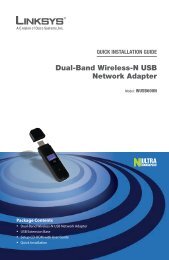
1 About this <strong>Guide</strong>This guide provides instructions on how to use Express Setup to initially configure your <strong>Catalyst</strong>switch. Also covered are switch management options, basic rack-mounting procedures, port andmodule connection procedures, and troubleshooting help.For additional installation and configuration information for <strong>Catalyst</strong> <strong>3560</strong>-E switches, see the<strong>Catalyst</strong> <strong>3560</strong>-E documentation on <strong>Cisco</strong>.com. For system requirements, important notes, limitations,open and resolved bugs, and last-minute documentation updates, see the release notes, also on<strong>Cisco</strong>.com.When using the online publications, refer to the documents that match the <strong>Cisco</strong> IOS software versionrunning on the switch. The software version is on the <strong>Cisco</strong> IOS label on the switch rear panel.For translations of the warnings that appear in this publication, see the Regulatory Compliance andSafety Information for the <strong>Catalyst</strong> 3750-E and <strong>Catalyst</strong> <strong>3560</strong>-E <strong>Switch</strong> that accompanies this guide.2 Taking Out What You NeedFollow these steps:1. Unpack and remove the switch and the accessory kit from the shipping box.2. Return the packing material to the shipping container, and save it for future use.3. Verify that you have received the items shown on page 3. If any item is missing or damaged,contact your <strong>Cisco</strong> representative or reseller for instructions.Some switch models might include additional items that are not shown on page 3.4. For switches with the optional 1150-W power supply module (model C3K-PWR-1150WAC),install the power supply in the switch as described in the installation notes after you rack-mountthe switch.2
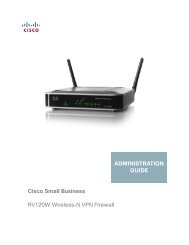
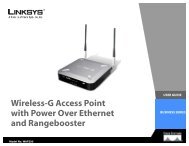
SYSTRPSMASTRSTATDUPLXSP EDSTACKPoEMODE1X2X1X12X49X2-1X2-2<strong>Catalyst</strong> <strong>3560</strong>-E SERIES PoE-48515052Shipping Box Contents12ProductDocumentationand Compliance1 2 3 4 5 6 7 8 9 10 1 1213 14 15 16 17 18 19 20 21 2 23 2413X 23X25 26 27 28 29 30 31 32 3 34 35 3625X 35X14X 24X37 38 3 9 40 41 42 43 4 45 46 47 4837X a26X 36X38X 48X3 4 56 78910 11 122073821 <strong>Catalyst</strong> switch 17 Four rubber mounting feet2 Documentation 8 Power cord retainer3 AC power cord 9 Twelve number-8 Phillips flat-head screws4 Console cable (optional) 10 Four number-12 Phillips machine screws5 Two 19-inch mounting brackets 11 One black Phillips machine screw6 Cable guide 12 Ground lug screw and ring terminal1. <strong>Catalyst</strong> <strong>3560</strong>E-48 Power over Ethernet (PoE) switch shown for example. Your switch model might look different.3
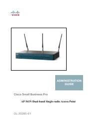
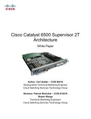
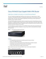
SYSTRPSMASTRSTATDUPLXSP EDSTACKPoEMODE1X2X1X12X49X2-1X2-251AC OK PS OK50521 0-240V ~1.0-5A50-60 HZ3 Running Express SetupWhen you first set up the switch, you should use Express Setup to enter the initial IP information.Doing this enables the switch to connect to local routers and the Internet. You can then access theswitch through the IP address for further configuration.You need this equipment to set up the switch:• A PC with Windows 2000 or XP installed• A web browser (Internet Explorer 5.5, 6.0, Netscape 7.1 or later) with JavaScript enabled• A straight-through or crossover Category 5 Ethernet cable to connect your PC to the switchDisable any pop-up blockers or proxy settings in your browser software and any wireless clientrunning on your PC.As an example, the Express Setup illustrations show the <strong>Catalyst</strong> <strong>3560</strong>E-48 PoE switch. You can runExpress Setup on all <strong>Catalyst</strong> <strong>3560</strong>-E switch models.To run Express Setup:Step 1Step 2Make sure that nothing is connected to theswitch.During Express Setup, the switch acts as aDHCP server. If your PC has a static IPaddress, change your PC settings before youbegin to temporarily use DHCP.Power the switch.For AC-powered switches, connect the ACpower cord to the switch power supply andto a grounded AC outlet.For DC-powered switches, see the wiringinstructions in the hardware installationguide on <strong>Cisco</strong>.com.1 2 3 4 5 6 7 8 9 10 1 1213 14 15 16 17 18 19 20 21 22 23 2413X 23X14X 24X25 26 27 28 29 30 31 32 3 34 35 3625X 35X 37X 47X37 38 3 9 40 41 42 43 4 45 46 47 4826X 36X 38X 48X<strong>Catalyst</strong> <strong>3560</strong>-E SERIES PoE-48Step 3Step 4When the switch powers on, it begins the power-on self-test (POST). During POST, theLEDs blink while tests verify that the switch functions properly.Wait for the switch to complete POST, which can take several minutes.Verify that POST has completed by confirming that the SYST LED remains green. If theswitch fails POST, the SYST LED turns amber. See the “In Case of Difficulty” section onpage 20 if your switch fails POST.4
Step 15Step 16(Optional) You can enter the Optional Settings information now or enter it later by usingthe device manager interface:• In the Host Name field, enter a name for the switch. The host name is limited to 31characters; embedded spaces are not allowed.• Enter the date, time, and time zone information in the System Date, System Time, andTime Zone fields. Click Enable to enable daylight saving time.(Optional) You can select the Advanced Settings tab on the Express Setup window and enterthe advanced settings now or enter them later by using the device manager interface.7
Step 17Step 18(Optional) Enter this information in the Advanced Setting fields:• In the Telnet Access field, click Enable if you are going to use Telnet to manage theswitch by using the command-line interface (CLI). If you enable Telnet access, you mustenter a Telnet password.• In the Telnet Password field, enter a password. The Telnet password can be from 1 to25 alphanumeric characters, is case sensitive, allows embedded spaces, but does notallow spaces at the beginning or end. In the Confirm Telnet Password field, re-enter theTelnet password.• In the SNMP field, click Enable to enable Simple Network Management Protocol(SNMP). Enable SNMP only if you plan to manage switches by using <strong>Cisco</strong>Works 2000or another SNMP-based network-management system.• If you enable SNMP, you must enter a community string in the SNMP Read Communityfield, the SNMP Write Community field, or both. SNMP community stringsauthenticate access to MIB objects. Embedded spaces are not allowed in SNMPcommunity strings. When you set the SNMP read community, you can access SNMPinformation, but you cannot change it. When you set the SNMP write community, youcan both access and change SNMP information.• In the System Contact and System Location fields, enter a contact name and the wiringcloset, floor, or building where the switch is located.(Optional) You can enable IPv6 on the switch in the Advanced Settings window. In theEnable IPv6 field, click Enable.NoteEnabling IPv6 restarts the switch when you complete Express Setup.Step 19Step 20To complete Express Setup, click Submit in the Network Settings or the Advanced Settingswindow to save your settings. Click Cancel to clear your settings.When you click Submit, the switch is configured and exits Express Setup mode. The PCdisplays a warning message and then tries to connect with the new switch IP address. If youconfigured the switch with an IP address that is in a different subnet from the PC,connectivity between the PC and the switch is lost. If you enabled IPv6, the switch restarts.Disconnect the switch from the PC, and install the switch in your production network. Seethe “Managing the <strong>Switch</strong>” section on page 9 for information about configuring andmanaging the switch.If you need to rerun Express Setup, see the “Resetting the <strong>Switch</strong>” section on page 21.8
Refreshing the PC IP AddressAfter you complete Express Setup, you should refresh the PC IP address:• For a dynamically assigned IP address, disconnect the PC from the switch, and reconnect the PCto the network. The network DHCP server assigns a new IP address to the PC.• For a statically assigned IP address, change it to the previously configured IP address.4 Managing the <strong>Switch</strong>After you complete Express Setup and install the switch in your network, use the device manager orother management options described in this section for further configuration.Using the Device ManagerThe simplest way to manage the switch is by using the device manager that is in the switch memory.This is a web interface that offers quick configuration and monitoring. You can access the devicemanager from anywhere in your network through a web browser.Follow these steps:1. Launch a web browser on your PC or workstation.2. Enter the switch IP address in the web browser, and press Enter. The device manager page appears.3. Use the device manager to perform basic switch configuration and monitoring. Refer to the devicemanager online help for more information.4. For more advanced configuration, download and run the <strong>Cisco</strong> Network Assistant, which isdescribed in the next section.Downloading <strong>Cisco</strong> Network Assistant<strong>Cisco</strong> Network Assistant is a software program that you download from <strong>Cisco</strong>.com and run onyour PC. It offers advanced options for configuring and monitoring multiple devices, includingswitches, switch clusters, routers, and access points. Network Assistant is free—there is no charge todownload, install, or use it.Follow these steps:1. Go to this Web address: http://www.cisco.com/go/NetworkAssistant.You must be a registered <strong>Cisco</strong>.com user, but you need no other access privileges.2. Find the Network Assistant installer.9
3. Download the Network Assistant installer, and run it. (You can run it directly from the Web ifyour browser offers this choice.)4. When you run the installer, follow the displayed instructions. In the final panel, click Finish tocomplete the Network Assistant installation.Refer to the Network Assistant online help and the getting started guide for more information.Command-Line InterfaceYou can enter <strong>Cisco</strong> IOS commands and parameters through the CLI. Access the CLI by connectingyour PC directly to the switch console port or to the Ethernet management port.Using the switch console port:Follow these steps:1. Connect the supplied RJ-45-to-DB-9 adapter cable to the standard 9-pin serial port on the PC.Connect the other end of the cable to the console port on the switch.2. Start a terminal-emulation program on the PC.3. Configure the PC terminal emulation software for 9600 baud, 8 data bits, no parity, 1 stop bit,and no flow control.4. Use the CLI to enter commands to configure the switch. See the software configuration guide andthe command reference for more information.Using the switch Ethernet management port:Follow these steps:1. Connect a Category 5 Ethernet cable to the PC Ethernet port. Connect the other end of the cableto the Ethernet management port on the switch rear panel.2. Start a Telnet session on the PC.3. Enter the switch IP address that you assigned by using Express Setup.4. Use the CLI to enter commands to configure the switch. See the software configuration guide andthe command reference for more information.10
Other Management OptionsYou can use SNMP management applications such as <strong>Cisco</strong>Works Small Network ManagementSolution (SNMS) and HP OpenView to configure and manage the switch. You also can manage itfrom an SNMP-compatible workstation that is running platforms such as HP OpenView orSunNet Manager.The <strong>Cisco</strong> IE2100 Series Configuration Registrar is a network management device that works withembedded <strong>Cisco</strong> Networking Services agents in the switch software. You can use IE2100 to automateinitial configurations and configuration updates on the switch.See the “Accessing Help Online” section on page 21 for a list of supporting documentation.5 Rack-MountingThis section covers basic 19-inch rack-mounting and switch port connections. As an example, all theillustrations show the <strong>Catalyst</strong> <strong>3560</strong>E-48 PoE switch. You can install and connect other<strong>Catalyst</strong> <strong>3560</strong>-E switches as shown in these illustrations. For additional installation and cablinginformation, see the hardware installation guide on <strong>Cisco</strong>.com.Equipment That You SupplyYou need a Phillips screwdriver to rack-mount the switch.Before You BeginBefore installing the switch, verify that these guidelines are met:• Clearance to front and rear panels is such that– Front-panel indicators can be easily read.– Access to ports is sufficient for unrestricted cabling.• For switches that support the RPS 2300, confirm that you have access to the switch rear panel toconnect the RPS 2300. If you do not have access to the rear panel, you should cable the switchesbefore you rack-mount them.• For switches with the optional 1150-W power supply module (model C3K-PWR-1150WAC), firstrack-mount the switch before installing the power supply module.• AC power cord can reach from the AC power outlet to the connector on the switch rear panel.11
• Cabling is away from sources of electrical noise, such as radios, power lines, and fluorescentlighting fixtures. Make sure the cabling is safely away from other devices that might damage thecables.• Airflow around the switch and through the vents is unrestricted.• Temperature around the unit does not exceed 113°F (45°C). If the switch is installed in a closedor multirack assembly, the temperature around it might be greater than normal room temperature.• For copper connections on Ethernet ports, cable lengths from the switch to connected devices canbe up to 328 feet (100 meters).• For cable lengths for X2 transceiver modules and SFP-module connections, see the hardwareinstallation guide on <strong>Cisco</strong>.com and the documentation that shipped with the module.Installation Warning StatementsThis section includes the basic installation warning statements. Translations of these warningstatements appear in the Regulatory Compliance and Safety Information for the <strong>Catalyst</strong> 3750-E and<strong>Catalyst</strong> <strong>3560</strong>-E <strong>Switch</strong> guide.WarningTo prevent the switch from overheating, do not operate it in an area that exceeds themaximum recommended ambient temperature of 113°F (45°C). To prevent airflowrestriction, allow at least 3 inches (7.6 cm) of clearance around the ventilation openings.Statement 17BWarningDo not reach into a vacant slot or chassis while you install or remove a module or a fan.Exposed circuitry could constitute an energy hazard. Statement 20612
WarningTo prevent bodily injury when mounting or servicing this unit in a rack, you must takespecial precautions to ensure that the system remains stable. The following guidelinesare provided to ensure your safety:• This unit should be mounted at the bottom of the rack if it is the only unit in the rack.• When mounting this unit in a partially filled rack, load the rack from the bottom to the top withthe heaviest component at the bottom of the rack.• If the rack is provided with stabilizing devices, install the stabilizers before mounting orservicing the unit in the rack. Statement 1006WarningThis unit is intended for installation in restricted access areas. A restricted access areacan be accessed only through the use of a special tool, lock and key, or other means ofsecurity. Statement 1017WarningOnly trained and qualified personnel should be allowed to install, replace, or service thisequipment. Statement 1030CautionTo comply with the Telcordia GR-1089 Network Equipment Building Systems (NEBS)standard for electromagnetic compatibility and safety, connect the Ethernet cables only tointrabuilding or nonexposed wiring or cabling.NoteThe grounding architecture of this product is DC-isolated (DC-I)13
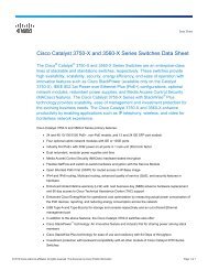
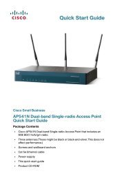
Before Attaching the BracketsTo install the switch in a rack, you must first remove the screws from the switch chassis so that themounting brackets can be attached. For attachment at the front-mounting position remove twoPhillips truss-head screws from the switch side panels. For some switch models, remove only one screwfrom the side panels. For attachment at the mid-mounting position, remove one screw. For attachmentat the rear-mounting position, remove one or two screws depending on the switch model.41 42 43 44 45 46 47 4820005347X49X2-150X2-248X<strong>Catalyst</strong> <strong>3560</strong>-E SERIES PoE-48515214
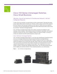
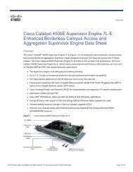
10-5 A50-60 HZAC OK PS OKAttaching the BracketsUse four number-8 Phillips flat-head screws to attach the long side of each bracket to the switch in oneof three mounting positions.1141 42 43 44 45 46 47 4847X49X2-150X2-2<strong>Catalyst</strong> <strong>3560</strong>-E SERIES PoE-4848X522513341 42 43 44 45 46 47 4847X49X2-150X2-2<strong>Catalyst</strong> <strong>3560</strong>-E SERIES PoE-4848X5225144100-240 V20005421 Front-mounting position 3 Mid-mounting position2 Number-8 Phillips flat-head screws 4 Rear-mounting position15
STATDUPLXSPEEDPoEMODE1X2XSTATDUPLXSPEEDPoEMODE1X2X1X12X1X12X49X2-1X2-251505249X2-1X2-2<strong>Catalyst</strong> <strong>3560</strong>-E SERIES PoE-4851AC OK PS OK50521 0-240V ~1.0-5A50-60 HZRack-Mount the <strong>Switch</strong>Use the four number-12 Phillips machine screws to attach the brackets to the rack. Use the blackPhillips machine screw to attach the cable guide to the left or right bracket.2 3SYSTRPS1 2 3 4 5 6 7 8 9 10 1 1213 14 15 16 17 18 19 20 21 2 23 2413X 23X25 26 27 28 29 30 31 32 3 34 35 3625X 35X14X 24X37 38 3 9 40 41 42 43 4 45 46 47 4837X 47X26X 36X138X 48X<strong>Catalyst</strong> <strong>3560</strong>-E SERIES PoE-48541 2 3 4 5 6 7 8 9 10 1 12SYSTRPS13 14 15 16 17 18 19 20 21 2 23 2413X 23X25 26 27 28 29 30 31 32 3 34 35 3625X 35X14X 24X37 38 3 9 40 41 42 43 4 45 46 47 4837X 47X26X 36X38X 48X642029381 Black Phillips machine screw 4 Number-12 Phillips machine screws2 Cable guide 5 Mid-mounting position3 Front-mounting position 6 Rear-mounting position16
6 Connecting to the <strong>Switch</strong> PortsThis section describes how to connect to the fixed switch ports, to the 10-Gigabit Ethernet moduleslots, and to the SFP module slots. Some switch models might not include 10/100/1000 Ethernet ports,10/100/1000 PoE ports, or SFP slots.Connect to 10/100/1000 PortsThe 10/100/1000 Ethernet ports use standard RJ-45 connectors with Ethernet pinouts. The maximumcable length is 328 feet (100 meters). The 100BASE-TX and 1000BASE-T traffic requires Category 5,Category 5e, or Category 6 UTP cable. The 10BASE-T traffic can use Category 3 or Category 4 cable.The autonegotiation feature is enabled by default on the switch. At this setting, the switch portsconfigure themselves to operate at the speed of attached devices. If the attached device does notsupport autonegotiation, you can explicitly set the switch port speed and the duplex parameters. Tomaximize performance, either let the ports autonegotiate both speed and duplex, or set the port speedand duplex parameters on both ends of the connection.For simplified cabling, the automatic medium-dependent interface crossover (auto-MDIX) feature isenabled by default on the switch. With auto-MDIX enabled, the switch detects the required cable typefor copper Ethernet connections and configures the interface accordingly. Therefore, you can use eithera crossover or a straight-through cable for connections to a switch 10/100/1000 Ethernet port,regardless of the type of device on the other end of the connection.See the switch software configuration guide or the switch command reference on <strong>Cisco</strong>.com for moreinformation about enabling or disabling autonegotiation and auto-MDIX.Connect to 10/100/1000 PoE PortsThe 10/100/1000 PoE ports have the same default settings and cabling requirements that are describedin the previous section.The PoE ports provide PoE support for devices compliant with IEEE 802.3af and also provide <strong>Cisco</strong>pre-standard PoE support for <strong>Cisco</strong> IP Phones and <strong>Cisco</strong> Aironet Access Points.Each port can deliver up to 15.4 W of PoE. With the 1150-W power supply module, the<strong>Catalyst</strong> <strong>3560</strong>E-48PS switch can deliver 15.4 W on all 48 ports. With the 750-W power supplymodule, the switches can deliver 15.4 W of PoE on any 24 of the 48 ports, or any combination of theports can deliver an average of 7.7 W of PoE at the same time, up to a maximum switch power outputof 370 W. On a per-port basis, you can control whether or not a PoE port automatically providespower when an IP phone or an access point is connected.See the hardware installation guide on <strong>Cisco</strong>.com for more information about the switch power supplyoptions.17
45 46 47 4847X49515052Install and Connect to Devices in the 10-Gigabit Ethernet SlotsThe switch 10-Gigabit Ethernet module slots are used for connections to other switches and routers.The module slots operate in full-duplex mode and use the hot-swappable <strong>Cisco</strong> X2 transceiver modulesand the <strong>Cisco</strong> TwinGig Converter Module. The X2 transceiver modules have SC connectors to connectto multimode fiber (MMF) and single-mode fiber (SMF) cables. The <strong>Cisco</strong> converter modules have twoSFP-module slots that convert the 10-Gigabit interface into a dual SFP interface.For switches with horizontal 10-Gigabit Ethernet module slots, position the module face up to installin the upper module slot (slot 1). Position the module face down to install in the lower module slot(slot 2).For switches with vertical 10-Gigabit Ethernet module slots, position the module top facing right toinstall in a vertical module slot.X2-1X2-248Xt <strong>3560</strong>-E SERIES PoE-4821X2-112223X2-1224200056When you install or remove the <strong>Cisco</strong> TwinGig converter module, the mode on the switch changesfrom 10-Gigabit Ethernet to Gigabit Ethernet or the reverse. During this mode change, data traffic onthe other switch uplink ports (X2 transceiver or SFP module ports) might temporarily stop. When youinstall or remove an X2 transceiver or SFP modules, traffic delay does not occur.Use only <strong>Cisco</strong> X2 transceiver modules, <strong>Cisco</strong> converter modules, and <strong>Cisco</strong> SFP modules with theswitch. Each <strong>Cisco</strong> module has an internal serial EEPROM that is encoded with security information.This encoding provides a way for <strong>Cisco</strong> to identify and validate that the module meets therequirements for the switch.18
Install SFP Modules and Connect to the Module PortsThe switch Gigabit Ethernet SFP modules are used for connections to other devices. These transceivermodules are field-replaceable, providing the uplink interfaces when inserted in an SFP module slot.You can use any combination of SFP modules. See the switch release notes for the list of SFP modulesthat the switch supports.To install an SFP module, position the module in front of the module slot. Insert the SFP module intothe slot until you feel the connector on the module snap into place.202373After installing the SFP module, use fiber-optic cables with LC or MT-RJ connectors to connect to afiber-optic SFP module. Use a Category 5 or higher cable with RJ-45 connectors to connect to a copperSFP module. For detailed instructions on installing, removing, and cabling the SFP module, see yourSFP module documentation.Use only <strong>Cisco</strong> SFP modules with the switch. Each SFP module has an internal serial EEPROM that isencoded with security information. This encoding provides a way for <strong>Cisco</strong> to identify and validatethat the SFP module meets the requirements for the switch.Verify Port ConnectivityAfter you connect a device to the switch port, the port LED turns amber while the switch establishesa link. This process takes about 30 seconds. Then the LED turns green when the switch and theattached device have an established link. If the LED is off, the device might not be turned on, theremight be a cable problem, or there might be a problem with the adapter installed in the device. See the“In Case of Difficulty” section on page 20 for information about online assistance.19
7 In Case of DifficultyIf you experience difficulty, help is available in this section and also on <strong>Cisco</strong>.com. This sectionincludes Express Setup troubleshooting, how to reset the switch, how to access help online, and whereto find more information.Troubleshooting Express SetupIf Express Setup does not run, or if the Express Setup page does not appear in your browser:• Did you verify that POST successfully ranbefore starting Express Setup?• Did you press the Mode button while theswitch was still running POST?• Did you try to continue without confirmingthat the switch was in Express Setup mode?If not, make sure that only the SYST and STATLEDs are green before pressing the Mode buttonto enter the Express Setup mode.POST errors are usually fatal. Contact your <strong>Cisco</strong>technical support representative if your switchfails POST.If yes, wait until POST completes. Power cycle theswitch. Wait until POST completes. Confirm thatthe SYST and STAT LEDs are green. Press theMode button to enter Express Setup mode.Verify that all LEDs above the Mode button aregreen. (The RPS LED is off.) If necessary, pressthe Mode button to enter Express Setup mode.• Does your PC have a static IP address? If yes, change your PC settings to temporarily useDHCP before connecting to the switch.• Did you connect the Ethernet cable to theconsole port instead of to a 10/100/1000Ethernet port or the 10/100 Ethernetmanagement port on the switch?• Did you wait 30 seconds after you connectedthe switch and the PC before you entered theIP address in your browser?• Did you enter the wrong address in thebrowser, or is there an error message?If yes, disconnect the cable from the console port.Then connect the cable to an Ethernet port on theswitch and on the PC. Wait 30 seconds before youenter 10.0.0.1 in the browser.If not, wait 30 seconds, re-enter 10.0.0.1 in thebrowser, and press Enter.If yes, re-enter 10.0.0.1 in the browser, and pressEnter.20
Resetting the <strong>Switch</strong>This section describes how to reset the switch by rerunning Express Setup. These are reasons why youmight want to reset the switch:• You installed the switch in your network and cannot connect to it because you assigned theincorrect IP address.• You want to clear all configuration from the switch and assign a new IP address.• You are trying to enter Express Setup mode, and the switch LEDs start blinking when you pressthe Mode button (which means that the switch is already configured with IP information).CautionResetting the switch deletes the configuration and reboots the switch.To reset the switch:• Press and hold the Mode button. The switch LEDs begin blinking after about 3 seconds. Continueholding down the Mode button. The LEDs stop blinking after 7 more seconds, and then the switchreboots.The switch now behaves like an unconfigured switch. You can enter the switch IP information by usingExpress Setup as described in the “Running Express Setup” section on page 4.Accessing Help OnlineFirst look for a solution to your problem in the troubleshooting section of the hardware installationguide or the software configuration guide on <strong>Cisco</strong>.com. You can also access the <strong>Cisco</strong> TechnicalSupport and Documentation website for a list of known hardware problems and extensivetroubleshooting documentation.21
For More InformationFor more information about the switch, see these documents on <strong>Cisco</strong>.com:• <strong>Catalyst</strong> 3750-E and <strong>Catalyst</strong> <strong>3560</strong>-E <strong>Switch</strong> Hardware Installation <strong>Guide</strong>• Regulatory Compliance and Safety Information for the <strong>Catalyst</strong> 3750-E and <strong>Catalyst</strong> <strong>3560</strong>-E<strong>Switch</strong>• Release Notes for the <strong>Catalyst</strong> 3750-E and <strong>Catalyst</strong> <strong>3560</strong>-E <strong>Switch</strong>• <strong>Catalyst</strong> 3750-E and <strong>Catalyst</strong> <strong>3560</strong>-E <strong>Switch</strong> Software Configuration <strong>Guide</strong>• <strong>Cisco</strong> Software Activation and Compatibility Document• <strong>Catalyst</strong> 3750-E and <strong>Catalyst</strong> <strong>3560</strong>-E <strong>Switch</strong> Command Reference• <strong>Catalyst</strong> 3750-E and <strong>Catalyst</strong> <strong>3560</strong>-E <strong>Switch</strong> System Message <strong>Guide</strong>• Documentation Updates for the <strong>Catalyst</strong> <strong>3560</strong>E-12D <strong>Switch</strong>• Installation Notes for the <strong>Catalyst</strong> 3750-E, <strong>Catalyst</strong> <strong>3560</strong>-E, and RPS 2300 Power SupplyModules• Installation Notes for the <strong>Catalyst</strong> 3750-E and <strong>Catalyst</strong> <strong>3560</strong>-E <strong>Switch</strong> Fan Modules• Installation Notes for the <strong>Cisco</strong> TwinGig Converter Module• <strong>Cisco</strong> Redundant Power System 2300 Hardware Installation <strong>Guide</strong>• <strong>Cisco</strong> Redundant Power System 2300 Compatibility Matrix8 Obtaining Documentation and Submitting a ServiceRequestFor information on obtaining documentation, submitting a service request, and gathering additionalinformation, see the monthly What’s New in <strong>Cisco</strong> Product Documentation, which also lists all newand revised <strong>Cisco</strong> technical documentation, at:http://www.cisco.com/en/US/docs/general/whatsnew/whatsnew.htmlSubscribe to the What’s New in <strong>Cisco</strong> Product Documentation as a Really Simple Syndication (RSS) feedand set content to be delivered directly to your desktop using a reader application. The RSS feeds are a freeservice and <strong>Cisco</strong> currently supports RSS Version 2.0.22
9 <strong>Cisco</strong> Warranty Terms<strong>Catalyst</strong> <strong>3560</strong>-E switches are covered by the <strong>Cisco</strong> Limited Lifetime Hardware Warranty. For moreinformation, see this document on <strong>Cisco</strong>.com:http://www.cisco.com/en/US/docs/general/warranty/English/LH2DEN__.htmlNoteIf you purchased your <strong>Catalyst</strong> <strong>3560</strong>-E switch before May 1, 2009, your switch is coveredby the <strong>Cisco</strong> 90-Day Limited Hardware Warranty. For more information, see thisdocument on <strong>Cisco</strong>.com:http://www.cisco.com/en/US/docs/general/warranty/English//901DEN__.htmlCCDE, CCENT, CCSI, <strong>Cisco</strong> Eos, <strong>Cisco</strong> Explorer, <strong>Cisco</strong> HealthPresence, <strong>Cisco</strong> IronPort, the <strong>Cisco</strong> logo, <strong>Cisco</strong> Nurse Connect, <strong>Cisco</strong> Pulse, <strong>Cisco</strong> SensorBase,<strong>Cisco</strong> StackPower, <strong>Cisco</strong> StadiumVision, <strong>Cisco</strong> TelePresence, <strong>Cisco</strong> TrustSec, <strong>Cisco</strong> Unified Computing System, <strong>Cisco</strong> WebEx, DCE, Flip Channels, Flip forGood, Flip Mino, Flipshare (Design), Flip Ultra, Flip Video, Flip Video (Design), Instant Broadband, and Welcome to the Human Network are trademarks;Changing the Way We Work, Live, Play, and Learn, <strong>Cisco</strong> Capital, <strong>Cisco</strong> Capital (Design), <strong>Cisco</strong>:Financed (Stylized), <strong>Cisco</strong> Store, Flip Gift Card, and One MillionActs of Green are service marks; and Access Registrar, Aironet, AllTouch, AsyncOS, Bringing the Meeting To You, <strong>Catalyst</strong>, CCDA, CCDP, CCIE, CCIP, CCNA,CCNP, CCSP, CCVP, <strong>Cisco</strong>, the <strong>Cisco</strong> Certified Internetwork Expert logo, <strong>Cisco</strong> IOS, <strong>Cisco</strong> Lumin, <strong>Cisco</strong> Nexus, <strong>Cisco</strong> Press, <strong>Cisco</strong> Systems, <strong>Cisco</strong> SystemsCapital, the <strong>Cisco</strong> Systems logo, <strong>Cisco</strong> Unity, Collaboration Without Limitation, Continuum, EtherFast, Ether<strong>Switch</strong>, Event Center, Explorer, Follow MeBrowsing, GainMaker, iLYNX, IOS, iPhone, IronPort, the IronPort logo, Laser Link, LightStream, Linksys, MeetingPlace, MeetingPlace Chime Sound, MGX,Networkers, Networking Academy, PCNow, PIX, PowerKEY, PowerPanels, PowerTV, PowerTV (Design), PowerVu, Prisma, ProConnect, ROSA, SenderBase,SMARTnet, Spectrum Expert, StackWise, WebEx, and the WebEx logo are registered trademarks of <strong>Cisco</strong> and/or its affiliates in the United States and certainother countries.All other trademarks mentioned in this document or website are the property of their respective owners. The use of the word partner does not imply a partnershiprelationship between <strong>Cisco</strong> and any other company. (1002R)Any Internet Protocol (IP) addresses used in this document are not intended to be actual addresses. Any examples, command display output, and figures includedin the document are shown for illustrative purposes only. Any use of actual IP addresses in illustrative content is unintentional and coincidental.<strong>Catalyst</strong> <strong>3560</strong>-E <strong>Switch</strong> <strong>Getting</strong> <strong>Started</strong> <strong>Guide</strong>© 2007–2010 <strong>Cisco</strong> Systems, Inc. All rights reserved.
Americas Headquarters<strong>Cisco</strong> Systems, Inc.San Jose, CAAsia Pacific Headquarters<strong>Cisco</strong> Systems (USA) Pte. Ltd.SingaporeEurope Headquarters<strong>Cisco</strong> Systems International BVAmsterdam, The Netherlands<strong>Cisco</strong> has more than 200 offices worldwide. Addresses, phone numbers, and fax numbers are listed on the<strong>Cisco</strong> Website at www.cisco.com/go/offices.Printed in the USA on recycled paper containing 10% postconsumer waste.OL-14460-04