NCR 7197 Thermal Receipt Printer Release 1.0 ... - Alsys Data
NCR 7197 Thermal Receipt Printer Release 1.0 ... - Alsys Data
NCR 7197 Thermal Receipt Printer Release 1.0 ... - Alsys Data

Create successful ePaper yourself
Turn your PDF publications into a flip-book with our unique Google optimized e-Paper software.
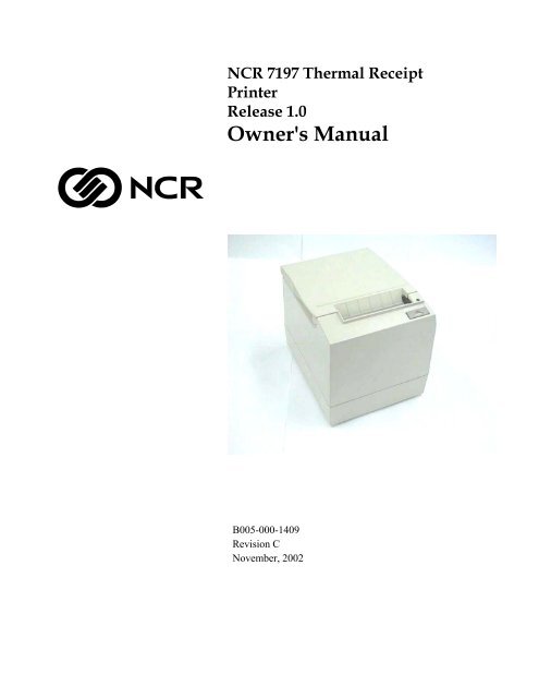
<strong>NCR</strong> <strong>7197</strong> <strong>Thermal</strong> <strong>Receipt</strong><strong>Printer</strong><strong>Release</strong> <strong>1.0</strong>Owner's ManualB005-000-1409Revision CNovember, 2002
The product described in this book is a licensed product of <strong>NCR</strong> Corporation.<strong>NCR</strong> is the registered trademark of <strong>NCR</strong> Corporation. Other trademarks and registered trademarks are the property of theirrespective holders.It is the policy of <strong>NCR</strong> Corporation (<strong>NCR</strong>) to improve products as new technology, components, software, and firmwarebecome available. <strong>NCR</strong>, therefore, reserves the right to change specifications without prior notice.All features, functions, and operations described herein may not be marketed by <strong>NCR</strong> in all parts of the world. In someinstances, photographs are of equipment prototypes. Therefore, before using this document, consult with your <strong>NCR</strong>representative or <strong>NCR</strong> office for information that is applicable and current.To maintain the quality of our publications, we need your comments on the accuracy, clarity, organization, and value of thisbook.Address correspondence to:Retail Systems Group−Atlanta<strong>NCR</strong> Corporation2651 Satellite Blvd.Duluth, GA 30136Copyright © 2002By <strong>NCR</strong> CorporationDayton, Ohio U.S.A.All Rights Reservedii
Important Information to the UserIn order to ensure compliance with the Product Safety, FCC and CE marking requirements, you must use the power supply,power cord, and interface cable which were shipped with this product or which meet the following parameters:Power SupplyUL Listed (QQGQ), Class 2 power supply with SELV (Secondary Extra Low Voltage), non-energy hazard output, limitedenergy source, input rated 100-240 Vac, 1.5/0.8 A, 50/60 Hz, output rated 24 Vdc, 2.3 A. or 3.15AUse of this product with a power supply other than the <strong>NCR</strong> power supply will require you to test this power supply and<strong>NCR</strong> printer for FCC and CE mark certification.Interface CableA shielded (360 degree) interface cable must be used with this product. The shield must be connected to the frame or earthground connection or earth ground reference at EACH end of the cable.Use of a cable other than described here will require that you test this cable with the <strong>NCR</strong> printer and your system for FCCand CE mark certification.Power CordA UL listed, detachable power cord must be used for this product. For applications where the power supply module may bemounted on the floor, a power cord with Type SJT marking must be used. For applications outside the US, power cords whichmeet the particular country’s certification and application requirements should be used.Use of a power cord other than described here may result in a violation of safety certifications which are in force in thecountry of use.iii
Federal Communications Commission (FCC)Radio Frequency Interference StatementWarning: Changes or modifications to this unit not expressly approved by the party responsible for compliance could void theuser’s authority to operate the equipment.Note: This equipment has been tested and found to comply with the limits for a Class A digital device, pursuant to Part 15 ofthe FCC Rules. These limits are designed to provide reasonable protection against harmful interference when the equipment isoperated in a commercial environment. This equipment generates, uses, and can radiate radio frequency energy and, if notinstalled and used in accordance with the instruction manual, may cause harmful interference to radio communications.Operation of this equipment in a residential area is likely to cause harmful interference in which case the user will be requiredto correct the interference at his own expense.Communication CablesShielded communication cables must be used with this unit to ensure compliance with the Class A FCC limits.Information to UserThis equipment must be installed and used in strict accordance with the manufacturer's instructions. However, there is noguarantee that interference to radio communications will not occur in a particular commercial installation. If this equipmentdoes cause interference, which can be determined by turning the equipment off and on, the user is encouraged to contact <strong>NCR</strong>immediately.The <strong>NCR</strong> company is not responsible for any radio or television interference caused by unauthorized modification of thisequipment or the substitution or attachment of connecting cables and equipment other than those specified by <strong>NCR</strong>. Thecorrection of interferences caused by such unauthorized modification, substitution or attachment will be the responsibility ofthe user.Industry Canada (IC)Radio Frequency Interference StatementThis Class A digital apparatus meets all requirements of the Canadian Interference-Causing Equipment Regulations.Cet appareil numérique de la classe A respecte toutes les exigences du Règlement sur le matériel brouilleur du Canada.iv
How to Use this BookWho Should Use this Book?How to Obtain More InformationUse this book as a general and technical reference manual and as a guide when replacingparts on the printer. The service guide is intended as a guide for service representatives,field engineers, and those who will be installing and learning about the <strong>7197</strong> printer. It canalso be used as a reference for service courses.See the Quick Reference page, the Contents, or the Index for detailed listings of what iscontained in this book.You must be a trained service representative to service the <strong>7197</strong> <strong>Thermal</strong> <strong>Receipt</strong> printer.For more information see the following documents:• <strong>7197</strong> <strong>Receipt</strong> <strong>Printer</strong>: Service Manual (B005-000-1410)• <strong>7197</strong> <strong>Receipt</strong> <strong>Printer</strong>: Parts Identification Manual (B005-000-1411)For this and additional copies of the Owner’s Manual, contact your sales representative.Revision RecordIssue Date RemarksA Apr 2002 First printingB May 2002 Update to reflect firstproduction configuration.vi
<strong>7197</strong> Owner’s Manual ContentsContentsQuick Reference ..........................................................................................................vHow to Use this Book.........................................................................................viWho Should Use this Book? ..............................................................................viHow to Obtain More Information ....................................................................viRevision Record .........................................................................................................viContents ......................................................................................................................ixChapter 1: About the <strong>7197</strong> <strong>Printer</strong> 1Features and Options ................................................................................................. 2<strong>Receipt</strong> Station...................................................................................................... 2General Features .................................................................................................. 3Options.................................................................................................................. 3<strong>Thermal</strong> Print Head.................................................................................................... 3Ordering Paper and Supplies.................................................................................... 4Ordering <strong>Thermal</strong> <strong>Receipt</strong> Paper....................................................................... 4Ordering Other Supplies .................................................................................... 5Ordering Documentation ................................................................................... 5Cleaning the <strong>Printer</strong>.................................................................................................... 6Cleaning the Cabinet........................................................................................... 6Cleaning the <strong>Thermal</strong> Print Head ..................................................................... 6Chapter 2: Setting Up and Using the <strong>Printer</strong> 8What Is in the Box? ..................................................................................................... 8Removing the Packing Material......................................................................... 9Repacking the <strong>Printer</strong>........................................................................................ 10Choosing a Location ................................................................................................. 10Wall mounted..................................................................................................... 11Wall mounted Power Supply (Option)........................................................... 11Setting Switches ........................................................................................................ 12Connecting the Cables.............................................................................................. 13About the Universal Serial Bus ............................................................................... 15Advantages of USB connections...................................................................... 15Advantages of the <strong>NCR</strong> USB Solution............................................................ 15Checking for USB Support on the Host Computer .............................................. 16Host Configuration............................................................................................ 16Configuring the <strong>Printer</strong>............................................................................................ 17Installing the USB <strong>Printer</strong> Drivers .......................................................................... 20Checking the Installation ......................................................................................... 30Configuring Serial Port Number Assignments..................................................... 33Running the Edgeport Utility .......................................................................... 33Serial Port Configuration Methods ................................................................. 34Uninstalling the Drivers ................................................................................... 34Using the <strong>Printer</strong>....................................................................................................... 36November 2002ix
Contents<strong>7197</strong> Owner’s GuideLoading and Changing the <strong>Receipt</strong> Paper............................................................. 37Removing the Paper Roll.................................................................................. 37Loading the Paper Roll ..................................................................................... 39Advancing Paper ............................................................................................... 40Chapter 3: Solving Problems 39Green LED Does Not Come On/<strong>Printer</strong> Will Not Print...................................... 40Green LED Blinking (Slow) ..................................................................................... 40Green LED Blinking (Fast)....................................................................................... 40<strong>Receipt</strong> Printing is Light or Spotty ......................................................................... 41Other Serious Problems ........................................................................................... 42Contacting a Service Representative ...................................................................... 42Chapter 4: Diagnostics 44Level 0 Diagnostics ................................................................................................... 44Level 1 Diagnostics ................................................................................................... 45<strong>Printer</strong> Configuration........................................................................................ 45Configuring the <strong>Printer</strong>..................................................................................... 46Communication Interface Modes .................................................................... 49Diagnostic Modes .............................................................................................. 51Emulation/Software Options .......................................................................... 53Hardware Options............................................................................................. 56Default Code Page ............................................................................................. 58EEPROM to Default Settings............................................................................ 60Level 2 Diagnostics ................................................................................................... 61Level 3 Diagnostics ................................................................................................... 62Chapter 5: Communication 61Communication Overview ...................................................................................... 61Interface............................................................................................................... 61Sending Commands .......................................................................................... 61RS-232C Interface...................................................................................................... 62Print Speed and Timing .................................................................................... 62XON/XOFF Protocol......................................................................................... 63DTR/DSR Protocol............................................................................................ 63RS-232C Technical Specifications .................................................................... 63Setting Extra RS-232C Options ........................................................................ 67Chapter 6: Commands 67Command Conventions ........................................................................................... 67Introduction............................................................................................................... 67List of Commands and Location............................................................................. 67By Command Code ........................................................................................... 68By Function......................................................................................................... 72<strong>Printer</strong> Function Commands............................................................................ 72Vertical Positioning and Print.......................................................................... 72Horizontal Positioning Commands ................................................................ 73Print Characteristic Commands....................................................................... 73xSeptember 1998
<strong>7197</strong> Owner’s Manual ContentsGraphics Commands......................................................................................... 74Status Commands.............................................................................................. 74Real Time Commands....................................................................................... 74Auto Status Back Commands........................................................................... 75Barcode Commands .......................................................................................... 75Page Mode Commands..................................................................................... 75Macro Commands ............................................................................................. 75User <strong>Data</strong> Storage Commands......................................................................... 76Asian Character Commands ............................................................................ 76Flash Download Commands............................................................................ 76Comparison Chart ............................................................................................. 77Command Descriptions ........................................................................................... 79<strong>Printer</strong> Function Commands............................................................................ 80Vertical Positioning and Print Commands .................................................... 86Horizontal Positioning Commands ................................................................ 92Print Characteristic Commands..................................................................... 100Graphics Commands....................................................................................... 116Status Commands............................................................................................ 126Real Time Commands..................................................................................... 137Auto Status Back Commands......................................................................... 143Bar Code Commands ...................................................................................... 146Page Mode Commands................................................................................... 152Macro Commands ........................................................................................... 160User <strong>Data</strong> Storage Commands....................................................................... 162Asian Character Commands .......................................................................... 170Flash Download Commands.......................................................................... 174Chapter 7: Reflashing the <strong>Printer</strong> Firmware 181Flash Utility Information ................................................................................ 181File Configurations.......................................................................................... 181<strong>Printer</strong> Languages Cross Reference............................................................... 182Appendix A: Specifications 199Printing Specifications............................................................................................ 199Power Requirements .............................................................................................. 200Environmental Conditions .................................................................................... 200Reliability ................................................................................................................. 201Dimensions and Weight......................................................................................... 201Density of <strong>Receipt</strong> Print Lines............................................................................... 201Duty Cycle Restrictions (Printing Solid Blocks) ................................................. 201Appendix B: Print Characteristics 203Character Size.......................................................................................................... 203<strong>Receipt</strong> Station.................................................................................................. 203Print Zones............................................................................................................... 204<strong>Receipt</strong> Station.................................................................................................. 204Character Sets.......................................................................................................... 206November 2002xi
Contents<strong>7197</strong> Owner’s GuideIndex ......................................................................................................................... 259xiiSeptember 1998
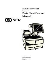
<strong>7197</strong> Owner’s Manual Chapter 1: About the <strong>7197</strong> <strong>Printer</strong>Chapter 1: About the <strong>7197</strong> <strong>Printer</strong><strong>Receipt</strong> Cover<strong>Receipt</strong>LEDPaper FeedButtonTop CoverThe <strong>7197</strong> printer is a fast, quiet, relatively small and very reliable multiplefunctionprinter. It prints receipts and two color printing.The industry-standard RS-232C communication interface allows the <strong>7197</strong> to beconnected to any host computer that uses RS-232C or USB communicationinterface.November 2002 1
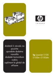
Chapter 1: About the <strong>7197</strong> <strong>Printer</strong><strong>7197</strong> Owner’s GuideFeatures and OptionsThe <strong>7197</strong> printer comes with several features and options.<strong>Receipt</strong> Station• <strong>Thermal</strong> printing• Standard pitch (host selectable): 15.2 characters per inch, 44 columns• Compressed pitch (host selectable): 19.0 characters per inch, 56 columns• Resident bar codes• Code 39• Code 93• Code 128• UPC-A• UPC-E• JAN8 (EAN)• JAN13 (EAN)• Interleaved 2 of 5• Codabar• PDF417• Drop-in paper loading requiring no spindle or threading paper• Paper low indicator• Paper exhaust indicator• Variety of print modes: double high, double wide, upside down, and rotated• 14 resident character language Code Pages:• PC Code Page 437 (US English)• PC Code Page 850 (Multilingual)• PC Code Page 852 (Slavic)• PC Code Page 858 (with Euo symbol)• PC Code Page 860 (Portuguese)• PC Code Page 862 (Hebrew)• PC Code Page 863 (French Canadian)• PC Code Page 864 (Arabic)• PC Code Page 865 (Nordic)• PC Code Page 866 (Cyrillic)• PC Code Page 1252 (Windows Latin #1)• PC Code Page Katakana• PC Code Page 874 (Thai)• Space Page• 16K RAM for downloaded character sets or bit-mapped graphics (such aslogos)2February 2002
<strong>7197</strong> Owner’s Manual Chapter 1: About the <strong>7197</strong> <strong>Printer</strong>General Features• Knife• Cover open sensors• One cash drawer connector (supports 2 cash drawers)• Industry standard RS-232C and USB communication interface• History EEROM for custom settings• Audible tone (controlled by application)Note: The <strong>7197</strong> does not have a paper journal. The journal is kept electronically bythe host computer.Options• Remote power supply• Communication cables<strong>Thermal</strong> Print HeadThe <strong>7197</strong> <strong>Receipt</strong> Station uses a thermal print head for printing receipts, and isextremely fast and quiet. Since it uses heat to print directly on paper, there is nocassette or ribbon to change, eliminating soiled fingers and paper dust.There is no regularly scheduled maintenance for the print head and it does notneed to be regularly cleaned. However, if it does appear dirty, wipe it with cottonswabs and rubbing alcohol. If spotty or light printing problems persist after thethermal print head has been cleaned, see “Chapter 3: Solving Problems” for moreinformation.Note: The thermal print head does not normally require cleaning if therecommended paper is used. If non-recommended paper has been used for anextended period of time, cleaning the print head with cotton swabs and rubbingalcohol will not be of much benefit. See “Ordering <strong>Receipt</strong> Paper” on the nextpage for the recommended paper.The print head is designed for a very long life, but it may be replaced if needed.Only a trained service representative may replace the print head. See “Chapter 3:Solving Problems” to determine if the print head needs to be replaced.November 2002 3
Chapter 1: About the <strong>7197</strong> <strong>Printer</strong><strong>7197</strong> Owner’s GuideOrdering Paper and SuppliesOrdering <strong>Thermal</strong> <strong>Receipt</strong> Paper<strong>Thermal</strong> receipt paper, ribbon cassettes, and forms can be ordered.Documentation is also available.The <strong>7197</strong> requires <strong>NCR</strong> qualified thermal paper to be used on the thermal receipt printstation to insure proper operation of the printer. In addition the paper rolls must be havethe following dimension.Diameter Length Width80 mm max. (3.15 in.) 83 meters (273 ft.) 80 mm ± .5 mm (3.15 ± .008 in.)The paper must not be attached at the core. Otherwise the receipt station will be damagedwhen the paper is exhausted.Paper grades available from <strong>NCR</strong>Paper StockPaper Grade Description856911 Economy (for text printing)856966 Standard Sensitivity (for text and simple graphics)878559 High Sensitivity (for text, bar codes & detailed graphics)856380 For improved archiveability and added resistance toincompatible substances856461 Red/Black856458 Blue/BlackThe paper must not be attached at the core. Otherwise the receipt station will be damagedwhen the paper is exhausted.To order thermal receipt paper, contact your sales representative or order from <strong>NCR</strong> at thefollowing address or toll free number:<strong>NCR</strong>Media Products Division9995 Washington Church RoadMiamisburg, OH 45342Voice: 1(800)543-8130 (toll free), or local listing of The <strong>NCR</strong> Media Productssales office4February 2002
<strong>7197</strong> Owner’s Manual Chapter 1: About the <strong>7197</strong> <strong>Printer</strong>Ordering Other SuppliesOrdering DocumentationContact your sales representative to order the supplies listed in the table.Item Type NumberPower supply with attached cable to 75 Watt Power Supply 7167-K331-V001printer and U.S. power supply cordPower supply ( w/o power cord) 75 Watt Power Supply 7167-K302-V001Power supply cord (to outlet)RS-232C Communication Cables9-pin to 9-pin9-pin to 9-pinDC Plus Power CablesDC Power from <strong>NCR</strong> POS TerminalDC Power from <strong>NCR</strong> POS TerminalUSB Communication CablesUSB Type A to Type B ConnectorUSB Type A to Type B ConnectorUSB Plus Power CablesUSB Plus Power to Type B ConnectorUSB Plus Power to Type B ConnectorUnited StatesInternational (no plug)United KingdomS.E.V.AustraliaInternational (with plug)0.7 meters3.0 meters (9.8 feet)<strong>1.0</strong> Meters4.0 Meters2.0 Meters4.0 Meters1406-C325-00301416-C319-00301416-C321-00301416-C320-00301416-C322-00301416-C323-00301416-C359-00071416-C266-00401416-C712-00101416-C712-00401416-C528-00101416-C528-0040<strong>1.0</strong> Meters1416-C713-00104.0 Meters1416-C713-0040Cash Drawer 2189 2189-K002-V001(Switchable forDrawer 1 or Drawer2)Cash Drawer Cable Y Cable 1416-C372-0006Contact your sales representative to obtain the following documentation:• <strong>7197</strong> <strong>Receipt</strong> <strong>Printer</strong>: Parts Identification Manual (B005-0000-1411)• <strong>7197</strong> <strong>Receipt</strong> <strong>Printer</strong>: Service Manual (B0005-0000-1410)(includes Troubleshooting Guide)• <strong>7197</strong> <strong>Receipt</strong> <strong>Printer</strong>: Owners Manual (B0005-0000-1409)November 2002 5
Chapter 1: About the <strong>7197</strong> <strong>Printer</strong><strong>7197</strong> Owner’s GuideCleaning the <strong>Printer</strong>Cleaning the CabinetCleaning the <strong>Thermal</strong> Print HeadThe external cabinet materials and finish are durable and resistant to these items:• Cleaning solutions• Lubricants• Fuels• Cooking oils• Ultraviolet lightThere is no scheduled maintenance required for the <strong>7197</strong>.Clean the cabinet as needed to remove dust and finger marks. Use any householdcleaner designed for plastics, but test it first on a small unseen area. If the receiptbucket is dirty, wipe it with a clean, damp cloth.Caution: Do not spray or try to clean the thermal print head or the inside of theprinter with any kind of cleaner as this may damage the thermal print head andelectronics.If the thermal print head appears dirty, wipe it with cotton swabs and isoprophlalcohol.If spotty or light printing problems persist after the thermal print head has beencleaned, see “Chapter 3: Solving Problems” for more information.Note: The thermal print head does not normally require cleaning if therecommended paper grades are used. If non-recommended paper has been usedfor an extended period of time, cleaning the print head with cotton swabs andrubbing alcohol will not be of much benefit. See “Ordering Paper and Supplies”earlier in this manual for recommended paper.6February 2002
Chapter 2: Setting Up and Using the <strong>Printer</strong><strong>7197</strong> Owner’s GuideChapter 2: Setting Up and Using the <strong>Printer</strong>What Is in the Box?The following items are packed in the shipping box:• <strong>Printer</strong> enclosed in a plastic bag and foam pack• <strong>Thermal</strong> receipt paper rollThese items may be ordered as options from <strong>NCR</strong> and will be shipped separately:• Communication cable (from host computer to printer)• DC Power Cable• Remote Power Supply• Cash drawer with cables (may be ordered from other equipment suppliers: see “OrderingOther Supplies” in chapter 1)8February 2002
<strong>7197</strong> Owner’s Manual Chapter 2: Setting Up and Using the <strong>Printer</strong>Removing the Packing Material<strong>Receipt</strong>Cover1. Remove the printer from the foam pack and plastic bag.2. Remove the receipt paper roll and cables from the foam packing material.3. Save all packing materials for future storing, moving, or shipping the printer.Note: If the printer is wall mounted the paper low switch must be disable.9 November 2002
Chapter 2: Setting Up and Using the <strong>Printer</strong><strong>7197</strong> Owner’s GuideRepacking the <strong>Printer</strong>Review the illustrations on the previous two pages to pack the printer.1. Place receipt paper between the receipt cover and the print head for protection.2. Place the printer in the plastic bag and foam pack, place the packed printer in thebox, and secure the box with packing tape.3. If you are sending the printer to <strong>NCR</strong> for repair, call your <strong>NCR</strong>-authorized servicerepresentative for instructions on where to send the printer.Be prepared to answer questions concerning shipping and billing.Choosing a LocationThe <strong>7197</strong> printer takes up relatively little counter space and may be set on or near thehost computer. Make sure there is enough room to open the receipt cover to change thepaper. The illustration shows the actual dimensions of the printer, but leave severalinches around the printer for connecting and accessing the cables.154.90 mm(6.20 in.)182.40 mm(7.30 in.)145.50 mm(5.80 in.)10February 2002
<strong>7197</strong> Owner’s Manual Chapter 2: Setting Up and Using the <strong>Printer</strong>Wall mountedThe <strong>7197</strong> printer may be mounted on a vertical wall by using the keyhole slot at the bottom of theprinter base. Make sure there is enough room to open the receipt cover to change the paper. Mountthe screws on the wall using the following recommended mount dimensions. Use a #8 wood screwwhich is to be securely fastened to a wall stud or using a “Molly” fastener (not provided).ScrewWall121mm (4.75 in.)3.5 ~ 4 mm(.138 – .160 in.)128 mm (5.04 in..)Note: Paper low must be disabled when printer is wall mountedWall mounted Power Supply (Option)The 75 watt power supply may be mounted on a vertical wall by using the holes on the cover.Mount the screws on the wall using the following recommended mount dimensions. Use a #8 woodscrew which is to be securely fastened to a wall stud or using “Molly” fasteners.75mm(2.95 in)10mm (.39 in)175mm (6.89 in)11 November 2002
Chapter 2: Setting Up and Using the <strong>Printer</strong><strong>7197</strong> Owner’s GuideSetting SwitchesThe DIP switches, located at the back of the printer, are used for two purposes:• To set variables for several printer functions (see the sections for the various printerfunctions in “Level 1 Diagnostics” in “Chapter 4: Diagnostics” for Setting Up the<strong>Printer</strong>)• To perform diagnostic tests (see the sections for the various diagnostic tests in “Level1 Diagnostics” in “Chapter 4: Diagnostics” for Setting Up the <strong>Printer</strong>)Caution: The DIP switches are set at the factory to predetermined settings and shouldnot be changed unless to change parameters or to reflash the firmware.DIP SwitchBottomCover2 1 ONSwitch 1 is shown inthe OFF positionBack of <strong>Printer</strong>Note: Switch 1 is shown in the Off position for reference.Use a paper clip or other pointed object to set the switches.1. Set the switches to the desired settings shown in the table.2. Reset the printer by disconnecting and reconnecting the power to theprinter.12February 2002
<strong>7197</strong> Owner’s Manual Chapter 2: Setting Up and Using the <strong>Printer</strong>Resetting the <strong>Printer</strong>The printer is reset by disconnecting/reconnecting the DC power.Connecting the CablesThere are three different types of cables that connect to the printer:• Power supply cable supplying power from the power supply• Communication cable (RS-232 or USB) connecting the printer to the host computer• Cash drawer cable connecting the printer to one or two cash drawersCaution: Disconnect the power before connecting the cables. Always connect thecommunication cable and cash drawer cables before connecting power to the powersupply. Always disconnect power to the power supply before disconnecting thecommunication and cash drawer cables.Follow these steps to connect the cables. See the illustration on the next page.1. Unplug the power supply from its power source.2. Connect the power and communication cables to their respective connectors underthe printer as shown in the illustration.For the RS232 Cable, be sure to screw the communication cable to the communicationconnector.3. Route the cables through the cable strain relief on the bottom of the printer, thenthrough the two slots in the cable access cover as shown in the illustration.4. Connect the communication cable to the appropriate host computer connector.5. Connect the cash drawer cable to the printer and cash drawer.The connectors is a standard phone jack located at the rear of the printer.6. Plug the power cord into the power supply for remote power supply installation,then plug the power supply into an outlet.13 November 2002
Chapter 2: Setting Up and Using the <strong>Printer</strong><strong>7197</strong> Owner’s GuideAt this point, the printer receives power. If the On Line LED (green) is on, the printer ison-line. Otherwise, the printer is off-line.7. For Host powered installation plug the DC cable into the POS terminal.RS-232 Cable ConnectionCommunicationConnectorPowerConnectorCommunicationCablePowerCableDIP SwitchCash DrawerCableCash DrawerConnectorUSB Cable ConnectionUSBConnectorPowerConnectorUSBCablePowerCableDIP Switch Cash DrawerCableCash DrawerConnectorBottom of the <strong>Printer</strong>14February 2002
<strong>7197</strong> Owner’s Manual Chapter 2: Setting Up and Using the <strong>Printer</strong>About the Universal Serial BusThe Universal Serial Bus (USB) is a peripheral bus for personal computers that was firstreleased in January 1996. Since that time, virtually all Intel Architecture personalcomputers have the hardware to support USB, and a large number of computers existthat have both the hardware and software support required to interface with USBperipherals.Advantages of USB connectionsUSB has a number of advantages over legacy connection schemes (e.g., serial RS-232).These advantages include:• High Speed: up to 12 MB/second for high-speed devices.• Plug and Play: Devices are automatically recognized and configured at installation.• Hot plug: Bus supports installation and removal of devices with the power applied.• Up to 127 devices: One host can support up to 127 devices with the use of hubs.• “Free ports”: Most PC architecture machines contain two USB ports in the basehardware.These advantages have become attractive to the POS industry for a couple of reasons.Additional POS devices. Some POS systems are required to host more peripherals thancan be supported by two RS-232 ports typical in a platform. With the addition of one (ortwo) USB connectors, the platform can now support the additional devices that hadpreviously required a serial port expander card.Higher bandwidths. New devices coming into use have bandwidth requirements thatare higher than the bandwidth that can be supported on legacy interfaces. These devicesinclude image scanners and printers. As the speed and capability of POS printersincreases, the performance of the printer in an application can become limited by thespeed of the communications interface. USB provides ample bandwidth to supportcurrent and future POS printer requirements.Advantages of the <strong>NCR</strong> USB Solution<strong>NCR</strong> has eliminated any cost associated with porting applications to USB byimplementing a USB solution that simulates standard serial communications in Windows98 (SR2), Windows 98 USB Hot Patch, ID: Q236934, and NT 4.0 (Service Pack 3 or higher)and Windows 2000. Application developers need only redirect their software to thevirtual serial ports created by the <strong>NCR</strong> USB solution to use the printer.15 November 2002
Chapter 2: Setting Up and Using the <strong>Printer</strong><strong>7197</strong> Owner’s GuideChecking for USB Support on the Host ComputerIf USB interface communications is required, the host computer must be equipped andsetup properly. If it is not, you need to install a USB interface card. With the requiredhardware in place, Windows 98 (SR2), Windows 98 USB Hot Patch, ID: Q236934, NT 4.0(Service Pack 4.0 or higher) and Windows 2000 (Service Pack 2.0 or higher) nativelysupport plug-and-play USB with a built-in driver; Windows NT does not, and the <strong>NCR</strong>windows NT USB driver needs to be installed.IMPORTANT: You need to have internet access to download the USB drivers from the<strong>NCR</strong> Web site://www.<strong>NCR</strong>.com.Host ConfigurationVerify that the proper hardware has been installed in the host PC.Windows 98:1. Open the Control Panel.2. Click on System (Windows 98).3. Click the Device Manager tab.4. In the Device Manager window, scroll down the list of installed hardware devicesuntil you find an entry for “Universal serial bus controller.”If this entry exists, your host computer is set up for USB operation. If this entry does notappear:• Consult your computer documentation to see if USB must be enabled in the BIOS setup.Windows NT:To see if your POS terminal is USB-compliant, look at the back.• If it has a USB connector port, your hardware is all set.Note: Even though the host may have a USB port, Windows NT does not nativelysupport plug-and-play USB because it does not have a built-in driver. You will need toload the <strong>NCR</strong> Windows NT USB driver (see “Installing the USB <strong>Printer</strong> Drivers”).• If the connector port is missing, you need to install a third-party USB card, accordingto the manufacturer’s instructions.Note: For Windows NT units requiring the installation of a card, a Windows 98 USB cardcan be used with the <strong>NCR</strong> Windows NT driver.Windows 2000:1. Open the Control Panel.2. Click on System.16February 2002
<strong>7197</strong> Owner’s Manual Chapter 2: Setting Up and Using the <strong>Printer</strong>3. Click the Device Manager tab.4. In the Device Manager window, scroll down the list of installed hardware devicesuntil you find an entry for “Universal serial bus controller.”If this entry exists, your host computer is set up for USB operation. If this entry does notappear:• Consult your computer documentation to see if USB must be enabled in the BIOS setup.Configuring the <strong>Printer</strong>USB is a plug-and-play environment. As such, neither the printer nor the host requiresuser configuration to work. However, since the <strong>NCR</strong> solution simulates a serialcommunication interface, you must configure “handshaking” on the printer for properoperation. The printer can be configured to use hardware flow control (usingDTR/DSR) or software flow control (using XON/XOFF). All other serialcommunication parameters (i.e., baud rate, parity, stop bits, and data bits) are ignored.To define software or hardware handshaking:1. Open the <strong>Receipt</strong> Cover and check whether there is paper in the printer. If thereisn’t, insert the paper roll, as described in the Owner’s Manual.2. Turn the printer so the back is facing you.3. Set DIP switch 1 to the On position (up).<strong>Receipt</strong> cover<strong>Receipt</strong>17 November 2002
Chapter 2: Setting Up and Using the <strong>Printer</strong><strong>7197</strong> Owner’s GuideDIP Switch2 1 ONBottomCoverSwitch 2 is shown inthe OFF positionBack of <strong>Printer</strong>4. Reset the printer. See below for information on resetting the printer.The printer beeps, prints the current configuration, then waits for you to make aselection from the Main Menu on the printout.DIP Switch Settings InformationSwitch 1 Settings Switch 2 Settings <strong>Printer</strong> StateOFF (0) OFF (0) On-line Mode (default)ON (1) OFF (0) Diagnostic ModeOFF (0) ON (1) Flash Download ModeON (1) ON (1) Vendor AdjustmentMode18February 2002
<strong>7197</strong> Owner’s Manual Chapter 2: Setting Up and Using the <strong>Printer</strong>*** Diagnostics Form ***Model numberSerial numberBoot FirmwareRevisionCRCFlash FirmwareRevisionCRCHardwareFlash Memory SizeFlash Logos SizeFlash Fonts SizeFlash User StorageCommunication InterfaceInterface Type :ParametersBaud Rate :<strong>Data</strong> Bits:Stop Bits:Parity:Flow Control :Reception Errors :Receive Buffer :Diagnostic ModeEmulation/Software<strong>Printer</strong> Emulation<strong>Printer</strong> ID ModeDefault LPICarriage ReturnAsian Mode:::::::::::::::::<strong>7197</strong>-1005-900101000011V00.179592V01.6217A52Mbytes256Kbytes64Kbytes64KbytesRS232/USB960081NoneDTR/DSRPrint ‘?’4KOff, Normal Mode7194 Native Mode7194 Native ID7.52Used as Print CmdOffTo enter <strong>Printer</strong> Configure Menu:1) Flip DIP switch #1 on2) Reset the printer by pressingand holding <strong>Receipt</strong> Feedswitch down whiledisconnecting and reconnectingthe power*** <strong>Printer</strong> Config Menu ***The config menu allows you to set generalprinter parameters. Sub-menus are entered andselections are made using the Paper FeedButton:- Short Click : Feed Button isquickly depressedthen released.- Long Click : Feed Button is helddown more than 1secthen released.CAUTION !!The settings are predetermined infactory and should generally not bechanged to avoid changing otherfunctions.*************************** Main Menu ******************************************************Select a sub –menu:- EXIT 1 Click- Print Current Configuration 2 Clicks- Set Communication Interface 3 Clicks- Set Diagnostics Modes 4 Clicks- Set Emulation/Software 5 Clicks- Set Hardware Options 6 Clicks- Set Default Code Page 7 Clicks- Set EEPROM To Default 8 ClicksEnter code, then hold button downat least 1 second to validateImportant: Ensure that the configurationsettings match your host computer, if not,enter the Configuration Menu to makechanges.Follow the instructions on the scrolling menu, pressing the Paper Feed button to makeselections. Indicate Yes with a long click, and No with a short click.19 November 2002
Chapter 2: Setting Up and Using the <strong>Printer</strong><strong>7197</strong> Owner’s Guide• Press and hold the Paper Feed button for at least one second for a long click.• Press the Paper Feed button quickly for a short click.5. Select Set Communication Interface from the Main Menu.The printer scrolls to the first question.6. Select RS232/USB.7. Skip through the parameters with short clicks until Set Flow Control Method isdisplayed.8. Follow the instructions to select either XON/OFF or DTR/DSR, then skip theremaining communications parameters.9. When you have finished, set DIP switch 1 to Off (down).10. Reset the printer.The printer resets with the new selection. You can verify the new setting by pressing thePaper Feed button to print out a diagnostics form or by holding the Paper Feed buttonwhile closing the Top Cover.Installing the USB <strong>Printer</strong> DriversWindows NT users need to run Service Pak 3 or higher for a successful installation andshould exit all Windows programs before starting.1. Verify that the printer is plugged in and the power is on.2. The installation varies depending on the operating system.Windows 98Follow the on-screen instructions. The printer beeps when the USB device isrecognized. Go to the location where you downloaded the drivers and double click thefile.20February 2002
<strong>7197</strong> Owner’s Manual Chapter 2: Setting Up and Using the <strong>Printer</strong>21 November 2002
Chapter 2: Setting Up and Using the <strong>Printer</strong><strong>7197</strong> Owner’s GuideNote: Location of the IONetworks files on the CD-ROM may very depending on the version ofthe CD that is being used.22February 2002
<strong>7197</strong> Owner’s Manual Chapter 2: Setting Up and Using the <strong>Printer</strong>Windows NTThe printer beeps when it is plugged in to show the USB device is recognized. Click onthe file you downloaded and follow the on-screen instructions.23 November 2002
Chapter 2: Setting Up and Using the <strong>Printer</strong><strong>7197</strong> Owner’s Guide24February 2002
<strong>7197</strong> Owner’s Manual Chapter 2: Setting Up and Using the <strong>Printer</strong>Windows 2000Follow the on-screen instructions. The printer beeps when the USB device isrecognized. Go to the location where you downloaded the drivers and double click thefile.25 November 2002
Chapter 2: Setting Up and Using the <strong>Printer</strong><strong>7197</strong> Owner’s Guide26February 2002
<strong>7197</strong> Owner’s Manual Chapter 2: Setting Up and Using the <strong>Printer</strong>Note: Location of the IONetworks files on the CD-ROM may very depending on the version ofthe CD that is being used.27 November 2002
Chapter 2: Setting Up and Using the <strong>Printer</strong><strong>7197</strong> Owner’s Guide28February 2002
<strong>7197</strong> Owner’s Manual Chapter 2: Setting Up and Using the <strong>Printer</strong>29 November 2002
Chapter 2: Setting Up and Using the <strong>Printer</strong><strong>7197</strong> Owner’s GuideChecking the InstallationYou need to verify that the device drivers were installed correctly:Windows 98:1. Open the Device Manager window, as you did in “Checking for USB Support.”2. Scroll down to “Universal serial bus controllers.”The following devices should be displayed:• <strong>NCR</strong> <strong>7197</strong> <strong>Printer</strong>• <strong>NCR</strong> <strong>7197</strong> Serial Ports [Port#] (where the # is the location of the printer)3. Scroll back up to “Ports.”You should see a COM number and port description for the <strong>NCR</strong> printer.If the devices are missing or are not listed correctly, the installation wasn’t successful.You will need to reinstall the drivers.30February 2002
<strong>7197</strong> Owner’s Manual Chapter 2: Setting Up and Using the <strong>Printer</strong>Windows NT:Go the Windows Start button and select Programs > InsideOut Networks Utilities >Edgeport Configuration Utility. A window opens that contains the name of the printer,and the port assignment.If this information is not listed, then the installation was not successful. You will needto reinstall the drivers.Windows 2000:1. Open the Device Manager window, as you did in “Checking for USB Support.”2. Scroll down to “Universal serial bus controllers.”31 November 2002
Chapter 2: Setting Up and Using the <strong>Printer</strong><strong>7197</strong> Owner’s Guide3. Scroll back up to “Ports.”If the devices are missing or are not listed correctly, the installation wasn’t successful.You will need to reinstall the drivers.If this information is not listed, then the installation was not successful. You will needto reinstall the drivers.32February 2002
<strong>7197</strong> Owner’s Manual Chapter 2: Setting Up and Using the <strong>Printer</strong>Configuring Serial Port Number AssignmentsThis section described how the <strong>NCR</strong> USB solution assigns serial port numbers (e.g.,COMx) to the printer. The information that determines the assigned port number isstored in the host computer and not in the printer. This assignment is made in one ofthree ways. The first method is the default method that automatically assigns a serialport number to the printer. The other two methods require the user to specify a portnumber. These methods are described more fully in “Serial Port ConfigurationMethods” on the following page.Running the Edgeport UtilityYou’ll need to run the Edgeport utility to check which serial port has been assigned tothe printer. This utility queries and configures the operating system and driver for theinformation regarding the virtual serial port.Windows 981. Open the Device Manager and make sure “View Devices By Type” is selected.2. Scroll down to Universal serial bus controller, and expand the list by pressing the“+” symbol. You’ll see two entries for your <strong>NCR</strong> printer.3. Select the printer name and click Properties.4. Select the Details tab, then press the Details button to start the Edgeport utility.33 November 2002
Chapter 2: Setting Up and Using the <strong>Printer</strong><strong>7197</strong> Owner’s GuideWindows NT 4.0From the Windows Start menu, select Programs > Inside Out Networks Utilities >Edgeport Configuration Utility.Serial Port Configuration MethodsAutomatic (Default). When the printer is plugged into the USB port of the host and thedrivers are loaded, the printer will default to the next available serial port number. Inmany cases this is exactly what is desired. You can check the assigned serial port byclicking the General tab in the Edgeport utility. You’ll see an entry for the <strong>NCR</strong> printer.Expand the list to see which serial port has been assigned to the printer.Assigning a serial port to the printer. If the default assignment does not meet therequirements of the installation, you can assign a different serial port to the printer.From the General tab of the Edgeport utility, select the printer and press Configure.Follow the directions on the resulting form to assign a new port to the printer.Associating a serial port with a specific USB port. (Windows 98 and NT) In certaininstallations it is desirable to associate a serial port number with a specific USB port.This is particularly important if multiple identical printers are installed on one host.Select the Advanced tab in the Edgeport utility, and follow the instructions forconfiguring the serial port number based on the physical USB port.Uninstalling the DriversWindows 98:1. Open the Device Manager and make sure “View Devices By Type” is selected.2. Scroll down to Universal serial bus controller, and expand the list by pressing the“+” symbol. You’ll see two entries for your <strong>NCR</strong> printer.3. Select the printer name and click Properties.4. Select the Details tab, then press the Details button to start the Edgeport utility.5. Click the Advanced tab.6. Click the Uninstall button and follow the on-screen instructions.34February 2002
<strong>7197</strong> Owner’s Manual Chapter 2: Setting Up and Using the <strong>Printer</strong>Windows NT:Windows NT users will need to run the Edgeport Configuration Utility to uninstall thedrivers.1. Press Windows Start Menu button.2. Choose Programs, then Inside Out Networks Utilities.3. Choose Edgeport Configuration Utility.4. Click the Advanced tab.5. Click the Uninstall button and follow the on-screen instructions.Windows 2000:1. Open the Device Manager and make sure “View Devices By Type” is selected.2. Scroll down to Universal serial bus controller, and expand the list by pressing the“+” symbol. You’ll see two entries for your <strong>NCR</strong> printer.3. Select the printer name and click Properties.4. Select the Details tab, then press the Details button to start the Edgeport utility.5. Click the Advanced tab.6. Click the Uninstall button and follow the on-screen instructions.35 November 2002
Chapter 2: Setting Up and Using the <strong>Printer</strong><strong>7197</strong> Owner’s GuideUsing the <strong>Printer</strong>LEDPaper FeedButtonNote: See “Setting Switches” earlier in this book for instructions on setting the DIPswitches.1. Connect the power supply to the printer and turn on the power source.The printer goes through a self-test routine to ensure everything is working properlythen “beeps.” After the printer has completed its “startup” cycle, it is ready to receivedata.If the LED blinks, or the host computer indicates that there is a problem, see “Chapter3: Solving Problems” for more information.2. To perform a Configuration check (optional), reset the printer while holding the PaperFeed Button, or open the receipt door and while pressing the paper feed button closethe receipt door, let go of the Paper Feed Button once the printing begins.Note: The printer receives power when the power supply is on even if the printer is offline.To completely remove power, unplug the power supply from the outlet, or turn thePOS terminal off.36February 2002
<strong>7197</strong> Owner’s Manual Chapter 2: Setting Up and Using the <strong>Printer</strong>Loading and Changing the <strong>Receipt</strong> PaperAlthough the illustrations show a used roll being removed, the instructions apply toloading paper for the first time.Change the paper when either of the following two conditions occurs:• LED blinks (slow): the paper is lowThere are approximately 1 ½ to 7 ½ meters (5-25 feet) of paper remaining on the roll.Change the paper as soon as possible to avoid running out part way through atransaction.Depending on the application program, the host computer may alert you when thepaper is low.• LED blinks (fast): the paper is outChange the paper immediately or data may be lost.Caution: Do not operate the printer or host computer if the printer runs out of paper.The printer will not operate without paper, but it may continue to accept data from thehost computer. Because the printer cannot print any transactions, the data may be lost.Removing the Paper Roll1. Open the receipt cover.2. Remove the used roll.37 November 2002
Chapter 2: Setting Up and Using the <strong>Printer</strong><strong>7197</strong> Owner’s Guide<strong>Receipt</strong>cover38February 2002
<strong>7197</strong> Owner’s Manual Chapter 2: Setting Up and Using the <strong>Printer</strong>Loading the Paper RollNote: Tear off the end of the new roll so that the edge is loose.1. Place the new roll in the bin with a little extra paper extending over the front.Be sure the paper unrolls from the bottom of the roll. Otherwise the paper will notbe printed on because the thermal coating will be on the wrong side.2. Close the receipt cover.3. Remove the excess paper by tearing it against the tear-off blade.1239 November 2002
Chapter 2: Setting Up and Using the <strong>Printer</strong><strong>7197</strong> Owner’s Guide3Advancing Paper1. Press the Paper Feed button on the operator panel to advance the paper.The cover must be closed. To ensure print quality and the proper alignment of thepaper, advance about 30 cm (12 inches) of paper.2. Tear off the excess paper against the tear-off blade.40February 2002
<strong>7197</strong> Owner’s Manual Chapter 3: Solving ProblemsChapter 3: Solving ProblemsThe <strong>7197</strong> printer is a simple, generally trouble-free printer, but from time to time minorproblems may occur. For example, the power supply may be interrupted or the thermalprint head may overheat.A green LED on the operator panel signals that something may be wrong.For some problems, the printer communicates the information to the host computer andrelies on the application to indicate what the problem is.The information on the following pages describes some problems that you may encounter:problems that you can easily fix, and others that you will need to contact a servicerepresentative for.You may be able to correct many of the conditions or problems without calling for service.However, if a problem persists, contact a service representative. See “Contacting a ServiceRepresentative” at the end of this chapter.November 2002 39
Chapter 3: Solving Problems<strong>7197</strong> Owner’s GuideGreen LED Does Not Come On/<strong>Printer</strong> Will Not PrintProblem What to Do Where to GoCables may not be connectedproperlyPower supply may be defectiveCheck all cable connections. Check that thehost computer and power supply are both on(the power supply is turned on by plugging itinto an outlet).If the power supply is plugged in, but doesnot come on, you will need to order a newpower supply.See “Connecting theCables” in chapter 2.See “Ordering OtherSupplies” in chapter 1.Green LED Blinking (Slow)Problem What to Do Where to Go<strong>Receipt</strong> paper is low* There are about 4 ½ meters, ± 3 meters, (15feet, ± 10 feet) of paper left. Change the papersoon to avoid running out of paper part waythrough a transaction.See “Loading andChanging the <strong>Receipt</strong>Paper” in chapter 2.Green LED Blinking (Fast)Problem What to Do Where to Go<strong>Receipt</strong> paper is outChange the paper now. Do not run atransaction without paper as the data may belost.See “Loading andChanging the <strong>Receipt</strong>Paper” in chapter 2.<strong>Receipt</strong> cover is openClose the cover. The printer will not operatewith the cover open.Knife failureOpen the receipt cover and check the knife.Clear any jammed paper you can see. Tear offany excess paper against the tear-off blade.AC supply voltage is out ofrangeContact a service representative if this doesnot resolve the problem.If paper is not low and no conditions indicatethat the thermal print head is too hot, then it islikely that the power supply voltage is out ofrange.See “Contacting a ServiceRepresentative” later inthis chapter.Contact a service representative if this doesnot resolve the problem.See “Contacting a ServiceRepresentative” later inthis chapter.40DFebruary 2002
<strong>7197</strong> Owner’s Manual Chapter 3: Solving Problems<strong>Thermal</strong> print head temperatureis out of rangeThe print head may overheat when printing ina room where the temperature is above therecommended operating temperature or whenprinting high-density graphics continuously,regardless of the room temperature. In eithercase, the printer will shut off.See “EnvironmentalConditions” in AppendixA for the recommendedtemperature range foroperating the printer.If the temperature of the print head is too hot,adjust the room temperature or move theprinter to a cooler location.If the print head is overheating because ofprinting high density graphics continuously,reduce the demand on the printer.Power supply voltage is out ofrangeIf the printer continues to overheat, contact aservice representative.If paper is not low and no conditions indicatethat the print head is too hot, the powersupply voltage is out of range. Contact aservice representative.See “Contacting a ServiceRepresentative” later inthis chapter.See “Contacting a ServiceRepresentative” later inthis chapter.<strong>Receipt</strong> Printing is Light or SpottyProblem What to Do Where to Go<strong>Thermal</strong> print head may be dirty Open the receipt cover and clean the thermalprint head with cotton swabs and isopropylalcohol.See “Cleaning the <strong>Printer</strong>”in chapter 2.Caution: Do not use the alcohol to clean otherparts of the printer. Damage will occur.Contact a service representative if this doesnot resolve the problem.See “Contacting a ServiceRepresentative” later inthis chapter.Note: The thermal print head does not normally require cleaning if therecommended paper grades are used. If non-recommended paper has beenused for an extended period of time, cleaning the print head with thealcohol and cotton swabs will not be of much benefit. See “Ordering<strong>Thermal</strong> Paper” in chapter 1 for recommended paper.November 2002 41
Chapter 3: Solving Problems<strong>7197</strong> Owner’s GuideOther Serious ProblemsThe following problems all need to be corrected by a qualified service representative. Seethe next section, “Contacting a Service Representative.”• <strong>Printer</strong> will not cycle or stop when required• Illegible characters• Paper will not feed• Knife will not cycle or cut• <strong>Printer</strong> will not communicate with HostContacting a Service RepresentativeFor serious problems, such as the printer not printing, not communicating with the hostcomputer, or not turning on, contact your <strong>NCR</strong>-authorized service organization to arrangefor a service call. In addition to the service guide listed below, other service-relatedmaterials may be available. Contact your <strong>NCR</strong>-authorized service representative to obtainthe service guide.• <strong>7197</strong> <strong>Thermal</strong> <strong>Receipt</strong> <strong>Printer</strong>: Service Manual (B005-000-1410)(includes the Troubleshooting Guide and the Preventative Maintenance Guide)• <strong>7197</strong> <strong>Thermal</strong> <strong>Receipt</strong> <strong>Printer</strong>: Parts Identification Manual (B005-000-1411)• <strong>7197</strong> <strong>Thermal</strong> <strong>Receipt</strong> <strong>Printer</strong>: Owners Manual (B005-000-1409)42DFebruary 2002
<strong>7197</strong> Owner’s Manual Chapter 3: Solving ProblemsNovember 2002 43
Chapter 4: Diagnostics<strong>7197</strong> Owner’s GuideChapter 4: DiagnosticsThe following diagnostic tests are available for the <strong>7197</strong>:• Level 0 Diagnostics (Startup)Performed during the startup cycle.• Level 1 Diagnostics (<strong>Printer</strong> Configuration)Allows configuration of the printer using a Configuration Menu that is printed on areceipt.• Level 2 Diagnostics (Runtime)The printer checks the status of these conditions during normal operation.• Level 3 Diagnostics (Remote)The printer keeps track of counters during normal operation.• Vendor AdjustmentPerformed in off-line mode. Allows to change settings for mechanical and performprinter test. Modifications of these settings are to be made by service personnel only.Level 0 DiagnosticsThe printer automatically performs level 0 diagnostics when it is put on-line. Level 0diagnostics comprise the following actions:• Motors are turned off.• Microprocessor timing is checked, CRC check of the firmware ROM is performed,external RAM is read.• The green LED flashes once if this action succeeds.• Level 0 diagnostics stop if this action fails. Failure is indicated by the printer goingdead: knife and print head do not home, LEDs are not lit, the printer is unable tocommunicate with the host computer.• Knife is homed. A fault condition is caused if this action fails.• The status of all sensors is checked, and the status bytes are updated.If the printer has not been turned on before the default values for the printer functions willbe loaded into the non volatile memory during level 0 diagnostics. These values can bechanged in level 1 diagnostics. See “Level 1 Diagnostics” for the functions and theirsettings.When the last step is complete, the Paper Feed button is enabled and the printer is readyfor normal operation. Information about the tests is available to the communicationinterface through the commands.44DFebruary 2002
<strong>7197</strong> Owner’s Guide Chapter 4: DiagnosticsLevel 1 Diagnostics<strong>Printer</strong> ConfigurationLevel 1 diagnostics (setup mode) allow you to change the settings for various printerfunctions and run certain tests.Keep the following information in mind when changing the settings:• The settings can only be changed when the printer is in level 1 diagnostics (setupmode): Switch 1 must be set to On and Switch 2 must be set to Off.• The default options are set at the factory and are stored in the history non volatilememory.• Once the settings have been changed and stored in the non volatile memory, thediagnostic setup is exited which saves the settings.Caution: If you are changing the printer settings, be sure they are the correct settings forthat particular function or test to avoid accidentally changing the settings for anotherfunction or test. If the settings are accidentally changed you must reenter the setup modeand reenter the correct settings. If you need assistance, contact a service representative.See “Contacting a Service Representative” in chapter 3.<strong>Printer</strong>s are generally shipped with all appropriate configuration settings pre-set at thefactory. The only time the user should need to change the printer configuration is if a newoption is installed, communication baud rate or the firmware is changed. It is also possiblethe user may need to run certain tests using the Configuration Menu.The user configures the printer using a convenient Configuration Menu that is printed onreceipt paper. The Configuration Menu prints instructions and setting optionsinteractively as the user goes through the configuration process. The following functionsand parameters can be changed with the scrolling Configuration Menu:• Configuring the <strong>Printer</strong>• Communication Interface• Interface Type• Baud Rate• Number of <strong>Data</strong> Bits• Number of Stop Bits• Parity• Flow Control• <strong>Data</strong> Reception Errors• Receive Buffer• Setting Diagnostic Modes• Off, Normal Mode• <strong>Data</strong>scope Mode• <strong>Receipt</strong> Test ModeNovember 2002 45
Chapter 4: Diagnostics<strong>7197</strong> Owner’s Guide• Setting Emulation/Software Options• Emulation• <strong>Printer</strong> ID• Default Lines Per Inch• Carriage Return Usage• Asian Mode• <strong>Receipt</strong> Synchronization• Setting Hardware Options• Print Density• Maximum Power Option• Paper Low Sensor• Paper Width• Set Knife Option• Color Paper Option• Setting Default Code Page• Setting EEPROM to default settingsConfiguring the <strong>Printer</strong>Use the Configuration Menu to select functions or change various settings as indicated inthe preceding sections. The Configuration Menu prints instructions and setting optionsinteractively as the user goes through the configuration process.Caution: Be extremely careful in changing any of the printer settings to avoid changingsettings that might affect the performance of the printer.BottomCover1. Set DIP Switch 1 to On, Switch 2 to Off.2. Reset the printer while holding the Paper Feed Button, the printer will print thecurrent configuration, then cuts the paper to print the Configuration Menu.46DFebruary 2002
<strong>7197</strong> Owner’s Guide Chapter 4: DiagnosticsPress the paper feed for the configuration you want.Defaults are marked with asterisk (*).******** Main Menu ***************************************Select a sub-menu:- EXIT -> 1 Click- Print Current Configuration -> 2 Clicks- Set Communication Interface -> 3 Clicks- Set Diagnostics Modes -> 4 Clicks- Set Emulation/Software Options -> 5 Clicks- Set Hardware Options -> 6 Clicks- Set Default Code page -> 7 Clicks- Set EEPROM To Default Settings -> 8 ClicksEnter code, then hold Button DOWNat least 1 second to validateNovember 2002 47
Chapter 4: Diagnostics<strong>7197</strong> Owner’s Guide*** Diagnostics Form ***Model numberSerial numberBoot FirmwareRevisionCRCFlash FirmwareRevisionCRCHardwareFlash Memory SizeFlash Logos SizeFlash Fonts SizeFlash User StorageCommunication InterfaceInterface Type :ParametersBaud Rate:<strong>Data</strong> Bits:Stop Bits:Parity:Flow Control :Reception Errors :Receive Buffer :Diagnostic ModeEmulation/Software<strong>Printer</strong> Emulation<strong>Printer</strong> ID ModeDefault LPICarriage Return::::::::::To enter <strong>Printer</strong> Configure Menu:3) Flip DIP switch #1 on4) Reset the printer by pressingand holding receipt feed switchdown while disconnecting andreconnecting the power.:::::<strong>7197</strong>A991703053V00.179592V01.3617A52Mbytes256Kbytes64Kbytes64KbytesRS232/USB960081NoneDTR/DSRPrint ‘?’4K bytesOFF, Normal Mode7194 Native Mode7194 Native ID7.52Used as Print Cmd*** <strong>Printer</strong> Config Menu ***The config menu allows you to setgeneral printer parameters. Sub-menusare entered and selections are madeusing the Paper Feed Button:- Short Click : Feed Button isquickly depressedthen released.- Long Click : Feed Button is heldDown more than 1secthen released.CAUTION !!The settings are predetermined infactory and should generally not bechanged to avoid changing otherfunctions.*************************** Main Menu ******************************************************Select a sub –menu:- EXIT 1 Click- Print Current Configuration 2 Clicks- Set Communication Interface 3 Clicks- Set Diagnostics Modes 4 Clicks- Set Emulation/Software 5 Clicks- Set Hardware Options 6 Clicks- Set Default Code Page 7 ClicksSet EEPROM To Default8 ClicksEnter code, then hold Button DOWMat least 1 second to validateImportant: Ensure that theconfiguration settings matchyour host computer, if not,enter the Configuration Menuto make changes.Configuration Menu and Print Test samples (show approximately 60% of size).48DFebruary 2002
<strong>7197</strong> Owner’s Guide Chapter 4: Diagnostics4. Press the Paper Feed Button to make the selections.The instructions indicate whether to select something with a short click, a long click, ora series of short clicks. Indicate Yes with a long click, No with a short click.Press and hold the Paper Feed Button for at least one second for a long click. Press thePaper Feed Button quickly for a short click.5. When finished, set DIP Switch 1 to Off and reset printer.Communication Interface ModesThe Configuration Menu gives the user the option of setting the printer to use an RS-232Cserial port. (See “Configuring the <strong>Printer</strong>” for instructions on how to enter theConfiguration Menu.)RS-232C Interface SettingsIf the user sets the printer to use an RS-232C serial interface, the Configuration Menu canbe used to set the following RS-232C specific settings:• Set a baud rate 115200, 57600, 38400, 19200, 9600, 4800, 2400, or 1200 baud• Set the number of data bits to seven or eight• Set the number of stop bits to one or two• Enable or disable parity• Set flow control to software (XON/XOFF) or Hardware (DTR/DSR)• Set the printer to ignore data errors or print a “?” upon encountering an errorThe settings used will depend on the software the operator is using and the capabilities ofthe host computer.Press the paper feed buton for the communications settings you want.Defaults are marked with asterisks (*).** SET INTERFACE TYPE ?YES -> Long ClickNO -> Short ClickRS232/USB* -> 1 ClickRS232 -> 2 ClicksUSB-> 3 ClicksEnter code, then hold Button DownAt least 1 second to validate** SET BAUD RATE ?YES -> Long ClickNO -> Short Click115200 Baud -> 1 Click57600 Baud -> 2 Clicks38400 Baud -> 3 ClicksNovember 2002 49
Chapter 4: Diagnostics<strong>7197</strong> Owner’s Guide19200 Baud -> 4 ClicksMore -> 5 ClicksEnter code, then hold Button DOWNAt least 1 second to validate9600 Baud* -> 1 Clicks4800 Baud -> 2 Clicks2400 Baud -> 3 Clicks1200 Baud -> 4 clicksEnter code, then hold Button DOWNAt least 1 second to validate** SET NUMBER OF DATA BITS ?YES -> Long ClickNO -> Short Click8 <strong>Data</strong> Bits* -> Long Click7 <strong>Data</strong> Bits -> Short Click** SET NUMBER OF STOP BITS ?YES -> Long ClickNO -> Short Click1 Stop Bits* -> Long Click2 Stop Bits -> Short Click** SET PARITY ?YES -> Long ClickNO -> Short ClickNo Parity* -> 1 ClickEven Parity -> 2 ClicksOdd Parity -> 3 ClicksEnter code, then hold Button DOWNAt least 1 second to validate** SET FLOW CONTROL METHOD ?YES -> Long ClickNO -> Short ClickSoftware (XON/XOFF) -> Long ClickHardware (DTR/DSR)* -> Short Click** SET DATA RECEPTION ERRORS OPTION ?YES -> Long ClickNO -> Short ClickIgnore Errors -> Long ClickPrint ‘?’* -> Short ClickNote: Press the Paper Feed Button for at least one second to validate the selection.50DFebruary 2002
<strong>7197</strong> Owner’s Guide Chapter 4: DiagnosticsReceive Buffer Size OptionThis function allows the user to set the buffer size to a single line or a 4 K buffer.Press the Paper Feed Button for the option you want.** SET RECEIVE BUFFER SIZE ?YES -> Long ClickNO -> Short Click4K Buffer*One Line-> Long Click-> Short ClickNote: Press the Paper Feed Button for at least one second to validate the selection.Save ParametersThis function allows to save the selected communication settings or return to thecommunication settings to select additional options.Press the Paper Feed Button for the option you want.Save new parameters ?YESNO, MODIFY-> Long Click-> Short ClickDiagnostic ModesThis function allows the user to put the printer into the following diagnostic modes: OFF, Normal Mode: this is the normal operating mode of the printer. <strong>Data</strong>scope Mode: the receipt printer prints incoming commands and data inhexadecimal format. <strong>Receipt</strong> Test Mode: the receipt printer prints two code pages.The diagnostic modes are enabled or disabled by using the Configuration Menu. See“Configuration the <strong>Printer</strong>,” for instructions on how to enter the Configuration Menu.Press the Paper Feed Button for the diagnostic mode you want.** SET DIAGNOSTICS MODE ?YES -> Long ClickNO -> Short ClickOFF, Normal Mode* -> 1 Click<strong>Data</strong> Scope Mode -> 2 Clicks<strong>Receipt</strong> Test Mode -> 3 ClicksEnter code, then hold Button DOWNAt least 1 second to validateEnter code, then hold Button DOWNAt least 1 second to validateNovember 2002 51
Chapter 4: Diagnostics<strong>7197</strong> Owner’s Guide<strong>Data</strong>scope Mode<strong>Data</strong>scope Mode allows the user to test the printer’s communications. When in <strong>Data</strong>scopeMode the printer receives all communications, but instead of executing the commands itprints them out on receipt paper as hexadecimal numbers in the order received. Forexample, the ASCII character “A” is printed as the hexadecimal number 41 an so on.To run the <strong>Data</strong>scope Mode:1. After you have enabled the <strong>Data</strong>scope Mode through the Configuration Menu, exit theConfiguration Menu.2. Run a transaction from the host computer.All commands and data sent from the host computer will be printed as hexadecimalnumbers as shown in the illustration.30 31 32 33 34 35 36 37 38 39 40 41 : 0 1 2 3 4 5 6 7 8 9 @ A41 42 43 44 45 46 47 48 49 50 51 52 : A B C D E F G H I J K LTo exit the <strong>Data</strong>scope Mode:1. Enter the Configuration Menu again2. Disable the <strong>Data</strong>scope Mode3. Exit the Configuration MenuThe printer is in Normal Mode and can communicate with the host computer.<strong>Receipt</strong> Test ModeTo run the <strong>Receipt</strong> Test Mode:1. Enable the <strong>Receipt</strong> Test Mode through the Configuration Menu. See “Configuring the<strong>Printer</strong>,” for instructions on how to enter the Configuration Menu.2. Push Paper Feed Button and the receipt station will print all code pages.3. The test ends with a cut.4. Go to step 2 again to repeat this test.To exit the <strong>Receipt</strong> Test Mode:1. Enter the Configuration Menu again.2. Disable the <strong>Receipt</strong> Test Mode3. Exit the Configuration MenuThe printer is in Normal Mode and can communicate with the host computer.Save ParametersThis function allows to save the selected diagnostics modes or return to the diagnosticsmode to select additional options.Press the Paper Feed Button for the option you want.52DFebruary 2002
<strong>7197</strong> Owner’s Guide Chapter 4: DiagnosticsSave ParametersThis function allows to save the selected communication settings or return to thecommunication settings to select additional options.Press the Paper Feed Button for the option you want.Save new parameters ?YES-> Long ClickNO, MODIFY -> Short ClickEmulation/Software Options<strong>Printer</strong> Emulations<strong>Printer</strong> emulations determine the commands that are available to the printer. They are setby using the Configuration Menu. (See “Configuring the <strong>Printer</strong>,” for instructions on howto enter the Configuration Menu.). The available options are:• 7194 Mode• 7193 Mode• <strong>7197</strong> Native ModePress the Paper Feed Button for the emulation you want.** SET EMULATION ?YES -> Long ClickNO -> Short Click7194 Mode* -> 1 Click7193 Mode -> 2 Click<strong>7197</strong> Mode -> 3 ClickEnter code, then hold Button DOWNAt least 1 second to validateNote: Press the Paper Feed Button for at least one second to validate the selection.<strong>Printer</strong> ID Selections<strong>Printer</strong> ID Selections determines the print ID that is returned from the printer. This is setby using the Configuration Menu. (See “Configuring the <strong>Printer</strong>,” for instructions on howto enter the Configuration Menu.). The available options are:• <strong>7197</strong> Native ID• Emulated Print ID• <strong>7197</strong> Native IDPress the Paper Feed Button for the emulation you want.November 2002 53
Chapter 4: Diagnostics<strong>7197</strong> Owner’s Guide** SET PRINTER ID MODE ?YES -> Long ClickNO -> Short Click7194 Native ID* -> 1 ClickEmulated <strong>Printer</strong> ID -> 2 Clicks7167 Native ID -> 3 ClicksEnter code, then hold Button DOWNAt least 1 second to validateNote: Press the Paper Feed Button for at least one second to validate the selectionDefault Lines Per InchThis function allows the user to set the default lines per inch printed by the thermal printerto 6, 7.52 or 8.13. (See “Configuring the <strong>Printer</strong>” for instructions on how to enter theConfiguration Menu to change this setting.)Press the Paper Feed Button for the lines per inch you want.** SET DEFAULT LINES PER INCH ?YES -> Long ClickNO -> Short Click8.13 Lines per Inch -> 1 Click7.52 Lines per Inch* -> 2 Clicks6 Lines per Inch -> 3 ClicksEnter code, then hold Button DOWNAt least 1 second to validateNote: Press the Paper Feed Button for at least one second to validate the selection.Carriage Return UsageThis function allows the printer to ignore or use the Carriage Return (hexadecimal 0D)command depending on the application. Some applicatons expect the command to beignored while others use the command as a print command. (See “Configuring the<strong>Printer</strong>” for instructions on how to enter the Configuration Menu to change this setting.)Press the Paper Feed Button for the carriage return usage you want.** SET CARRIAGE RETURN USAGE ?YES -> Long ClickNO -> Short ClickIgnore CRUse CR as Print Cmd*-> Long Click-> Short ClickNote: Press the Paper Feed Button for at least one second to validate the selection.54DFebruary 2002
<strong>7197</strong> Owner’s Guide Chapter 4: DiagnosticsAsian ModeThis function makes it possible for the user to select an Asian character for the printer. (See“Configuring the <strong>Printer</strong>” for instructions on how to enter the Configuration Menu tochange this setting.)Note: For Asian code pages, only one (either 932, 936, 949 or 950) will exist in thefirmware.Press the Paper Feed Button for the asian mode you want.** SET ASIAN MODE ?YES -> Long ClickNO -> Short ClickAsian Mode OnAsian Mode Off*-> Long Click-> Short ClickNote: Press the Paper Feed Button for at least one second to validate the selection.<strong>Receipt</strong> Synchronization ModeThe standard mode for synchronization allows for verification of each line printed to thehost. When the receipt synchronization is disabled the printer will allow for maximumprint speed and ignore the verificaiton of each line printed.Press the Paper Feed Button for the receipt synchronization mode option you want.** SET RECEIPT SYNCHRONIZATON MODE ?YES -> Long ClickNO -> Short ClickEnable <strong>Receipt</strong> Sync.* -> Long ClickDisable <strong>Receipt</strong> Sync. ->Short ClickNote: Press the Paper Feed Button for at least one second to validate the selection.Save ParametersThis function allows to save the selected emulations/software settings or return to theemulations/software settings to select additional options.Press the Paper Feed Button for the option you want.Save new parameters ?YES-> Long ClickNO, MODIFY -> Short ClickNovember 2002 55
Chapter 4: Diagnostics<strong>7197</strong> Owner’s GuideHardware OptionsPrint DensityThis function makes it possible to adjust the energy level of the print headto darken theprintout. An adjustment should only be made when necessary. The factory setting is 100%.Warning: Choose an energy level no higher than necessary to achieve a dark printout.Failure to observe this rule may result in a printer service call or voiding of the printerwarranty. Consult your <strong>NCR</strong> technical support specialist if you have any questions.Press the Paper Feed Button for the print density you want.** SET PRINT DENSITY ?YES -> Long ClickNO -> Short Click100 %* -> 1 Click110 % -> 2 Clicks120 % -> 3 ClicksEnter code, then hold Button DOWNAt least 1 second to validateNote: Press the Paper Feed Button for at least one second to validate the selection.Maximum Power OptionThis function allows the user to set the maximum power for the printer to 75W or 55W.Press the Paper Feed Button for the option you want.** SET MAX POWER OPTION ?YES -> Long ClickNO -> Short Click55W Power Supply*75W Power Supply-> Long Click-> Short ClickNote: Press the Paper Feed Button for at least one second to validate the selection.56DFebruary 2002
<strong>7197</strong> Owner’s Guide Chapter 4: DiagnosticsPaper Low SensorPaper Low Sensor makes it possible to enable or disable the paper low sensor forparticular printer configurations.Press the Paper Feed Button for the option you want.** SET PAPER LOW SENSOR OPTION ?YES -> Long ClickNO -> Short ClickEnable Paper Low Sensor*Disable Paper Low Sensor-> Long Click-> Short ClicksNote: Press the Paper Feed Button for at least one second to validate the selection.Paper WidthThis function allows the user to set the default paper width for the receipt thermal printerto 58mm or 80mm wide.Press the Paper Feed Button for the paper width option you want.** SET PAPER WIDTH ?YES -> Long ClickNO -> Short ClickPaper Width = 80 mm* -> 1 ClickPaper Width = 58 mm -> 2 ClicksEnter code, then hold Button DOWNAt least 1 second to validateNote: Press the Paper Feed Button for at least one second to validate the selection.Set Knife OptionSet the Knife option using the configuration menu. Answer No to the questions printed onthe receipt until you come to the instructions for knife option.Caution: Be extremely careful changing any of the printer settings to avoid inadvertentlychanging other settings that might affect the performance of the printer.Press the Paper Feed Button for the option you want.** SET KNIFE OPTION ?YES -> Long ClickNO -> Short ClickEnable Knife*Disable Knife-> Long-> ShortNovember 2002 57
<strong>7197</strong> Owner’s Guide Chapter 4: DiagnosticsPress the Paper Feed Button for the Default Code Page you want.** SET CODE PAGE ?YES -> Long ClickNO -> Short ClickCode Page 437* -> 1 ClickCode Page 850 -> 2 ClicksCode Page 852 -> 3 ClicksCode Page 858 -> 4 ClicksMore Options -> 5 ClicksEnter code, then hold Button DOWNAt least 1 second to validateCode Page 860 -> 1 ClickCode Page 862 -> 2 ClicksCode Page 863 -> 3 ClicksCode Page 864 -> 4 ClicksMore Options -> 5 ClicksEnter code, then hold Button DOWNAt least 1 second to validateCode Page 865 -> 1 ClickCode Page 866 -> 2 ClicksCode Page 874 -> 3 ClicksCode Page 1252 -> 4 ClicksMore Options -> 5 ClicksEnter code, then hold Button DOWNAt least 1 second to validateCode Page Katakana -> 1 ClickCode Page 932-> 2 ClicksEnter code, then hold Button DOWNAt least 1 second to validateNote: Press the Paper Feed Button for at least one second to validate the selection.For Asian code pages, code page 936, 949 or 950 replaces code page 932 in the aboveshown menu. Only one Asian code page (Either 932, 936, 949 or 950) will exist infirmware.Save ParametersThis function allows to save the selected default code page selecton or return to the defaultcode page selecton to select additional options.Press the Paper Feed Button for the option you want.Save new parameters ?YES-> Long ClickNO, MODIFY -> Short ClickNovember 2002 59
Chapter 4: Diagnostics<strong>7197</strong> Owner’s GuideLevel 3 DiagnosticsLevel 3 diagnostics keeps track of the following tallies and prints them on the receiptduring the receipt test.• Serial number• Model number• CRC number• Number of receipt lines printed• Number of knife cuts• Number of hours printer is on• Number of flash cycles• Maximum temperature reached• Number of cutter jams• Number of times the door is open62DFebruary 2002
<strong>7197</strong> Owner’s Guide Chapter 4: DiagnosticsNovember 2002 63
<strong>7197</strong> Owner’s Manual Chapter 5: CommunicationsChapter 5: CommunicationCommunication OverviewIn order for a receipt to be printed, a program must be in place that translates the datafrom the host computer into a language that the printer can understand. This programmust tell the printer exactly how to print each character. This chapter describes how tocreate such a program or modify an existing one.InterfaceIn order for the printer to communicate with the host, a communication link must be setup. The <strong>7197</strong> supports the industry standard RS-232C communication interface. Thisinterface has a protocol associated with it that the host computer must understand andadhere. The priner also supports USB communications.Only when the interface parameters are matched and the proper protocol is used will thehost and the printer be able to communicate. See the section, “RS-232C Interface” on thenext page for a description of the protocol associated with the RS-232C interface.Sending CommandsOnce the communication link is established, commands can be sent to the printer. Thissection describes how to send commands to the printer using DOS and BASIC. Thissection does not take into account the necessary protocol, but is meant as a generalintroduction to how the printer functions.Using DOS to Send CommandsOne way of getting commands to the printer is to send them directly from DOS. Forexample, the commandCOPY CON: COM1:This sets the computer up such that the Hex code corresponding to any key that waspressed would be sent to the RS-232C communication port COM1 when the COPY modeis exited. If the printer is connected to COM1, then the data will go to the printer.Exit the COPY mode by typingCTRL Zand then pressing the ENTER key. This directs the data from any print command to theproper port, commands can be sent from any software program.61November 2002
Chapter 5: Communications<strong>7197</strong> Owner’s GuideUsing BASIC to Send CommandsIn BASIC, printer commands are sent as a string of characters preceded by the LPRINTcommand. For example,LPRINT CHR$(&H0A)sends the hexadecimal number 0A to the printer, which causes the printer to print thecontents of its print buffer. Previously sent commands tell the printer exactly how this datashould appear on the paper. For example,LPRINT CHR$(&H12); "ABC"; CHR$(&H0A)sends the Hex numbers 12 41 42 43 0A to the printer. This causes the printer to set itself todouble wide mode (12), load the print buffer with “ABC” (41 42 43), and finally, print (0A).Again, the communication link that the BASIC program outputs to must be matched tothat of the printer.RS-232C InterfacePrint Speed and TimingThe RS-232C interface uses either XON/XOFF or DTR/DSR protocol. For XON/XOFF, aparticular character is sent back and forth between the host and the printer to regulate thecommunication. For DTR/DSR, changes in the DTR/DSR signal coordinate the data flow.The RS-232C version of the <strong>7197</strong> offers the standard options which are selectable in theDiagnostic mode. See “Diagnostics: Communications Interface Settings” later in this book.The fast speed of the printer requires the application to send data to the printer at least asfast as it is printed. This application must also allow receipt lines to be buffered ahead atthe printer, so the printer can print each line immediately after the preceding line, withoutstopping to wait for more data. Ideally, the application will send all the data for an entirereceipt without pausing between characters or lines transmitted.If the application sends data at 9600 baud and pauses between lines for as little as 50milliseconds, the printer will never be able to print at full speed. But, if the applicationsends data at 19.2 K baud and does not pause between lines, the printer will be able toprint at its full speed of 1020 lines/minute.The table shows that with a pause of 50 milliseconds after each line, the transmit timeequals or exceeds the print time, slowing down the printer, regardless of the baud rate.Char./Line Lines/<strong>Receipt</strong> Transmit Time: (9600 Baud) Transmit Time: (19.2 K Baud) Print Time20 20 1.4 Seconds 1.2 Seconds 1.2 Seconds20 40 2.8 Seconds 2.4 Seconds 2.4 Seconds44 20 1.88 Seconds 1.44 Seconds 1.2 Seconds44 40 3.76 Seconds 2.88 Seconds 2.4 SecondsThe next table shows that with no delay between lines, the transmit time is much less thanthe print time, allowing the printer to print at full speed.Char./Line Lines/<strong>Receipt</strong> Transmit Time: (9600 Baud) Transmit Time: (19.2 K Baud) Print Time20 20 0.4 Seconds 0.2 Seconds 1.2 Seconds20 40 0.8 Seconds 0.4 Seconds 2.4 Seconds44 20 0.88 Seconds 0.44 Seconds 1.2 Seconds44 40 1.76 Seconds 0.88 Seconds 2.4 SecondsFebruary 2002 62
<strong>7197</strong> Owner’s Manual Chapter 5: CommunicationsXON/XOFF ProtocolThe XON/XOFF characters coordinate the information transfer between the printer andthe host computer. The printer sends an XON character when it is ready to receive dataand it sends an XOFF character when it cannot accept any more data. The software on thehost computer must monitor the communication link as shown in the following flowchartin order to send data at the appropriate times.If XON/XOFF has been selected, the printer also toggles the DTR signal, as described inthe next section, but it does not look at the DSR signal to transmit data.DTR/DSR ProtocolXON character = Hex 11.XOFF character = Hex 13.The DTR signal is used to control data transmission to the printer. It is driven low whenthe printer is ready to recieve data and driven high when it cannot accept any more data.<strong>Data</strong> is transmitted from the printer after it confirms that the DSR signal is low.RS-232C Technical SpecificationsThis section describes the pin settings for the connectors and the RS-232C interfaceparameters. The RS-232C parameters are selectable in the Diagnostic mode. See“Diagnostics: Communications Interface Settings” in chapter 4 for the position of the DIPswitches. The RS-232C parameters must match those of the host.63November 2002
Chapter 5: Communications<strong>7197</strong> Owner’s GuideRS 232 ConnectorThe illustration shows the RS-232C communication connector and pin assignments. Theconnector is a 9-pin male D-shell connector and is located in the hollow cavity under theprinter at the rear.DC Power ConnectorThe illustration shows the power cable connector and pin assignments. The power cable connector isa 3-pin DIN plug and is located in the hollow cavity under the printer at the rear.February 2002 64
<strong>7197</strong> Owner’s Manual Chapter 5: CommunicationsCash Drawer ConnectorThe following illustration shows the pin out designation for the cash drawer connectors.The following table provides the pinout assignments for cash drawers one and two. Thecash drawer connectors are located at the rear of the printer.Pin 1 Pin 6Pin NumberCash Drawer 1 Connector1 Frame Ground2 Drawer 1 Solenoid3 Drawer 1 Status Switch4 +24 Volts (to Solenoid +)5 Drawer 2 Solenoid6 Ground (Status Switch Return)USB ConnectorThe following illustration is for the USB Type B communication connector and pinassignment.213 4Pin No Signal1 +5 V – USB2 <strong>Data</strong> -3 <strong>Data</strong> +4 Ground65November 2002
Chapter 5: Communications<strong>7197</strong> Owner’s GuideSwitch SettingsThe DIP switches are located on the PC board at the back of the printer as shown in theillustration in “Level 1 Diagnostics” in chapter 4.The switches are used to put the printer into various modes for printer configuration setup.<strong>Printer</strong> End ViewUse a paper clip or other pointed object to set the switches.1. Set the switches to the desired settings shown in the table.Caution: Do not set switch 1 to On. Setting switch 1 to On puts the printer in level 1diagnostics (setup mode) where other functions and tests can be changed.DIP Switch SettingsSwitch 1Switch 2 SettingSetting<strong>Printer</strong> StateOFF (0) OFF (0) On-line Mode (default)ON(1) OFF (0) Diagnostic ModeOFF (0) ON (1)* Flash Download ModeON (1) ON (1) Vendor Adjustment Mode* It is optional to set this switch to ON when reflashing the IPL firmware.February 2002 66
<strong>7197</strong> Owner’s Manual Chapter 5: CommunicationsSetting Extra RS-232C OptionsThe following extra options are available for the RS-232C Interface:• <strong>Data</strong> errors• Print “?” for data errors (default)• Ignore data errors67November 2002
Chapter 5: Communications<strong>7197</strong> Owner’s GuideFebruary 2002 68
<strong>7197</strong> Owner’s Guide Chapter 6: CommandsChapter 6: CommandsCommand ConventionsIntroductionThe different features and functions provided by the printer are controlled bysending commands from the host computer to the printer. This section describes thecommands that are supported by the printer. The printer commands are made up ofone or more bytes of data starting with a command control code followed by itssupporting parameters.Commands control all operations and functions of the printer. This includesselecting the size and placement of characters and graphics on the receipt or the slipand feeding and cutting the paper. Unless otherwise noted, any of the commandsmay be used in any combination to communicate with the printer from a program ina host computer.In order to allow the graceful handling of commands that may be available in otherprinters but are not available in this printer, some commands will be listed anddescribed but identified as "not implemented." If the printer receives one of these"not implemented" commands, the command and its supporting operands will bediscarded. Any other data bytes, including unrecognized commands, are sent to theprint buffer as data, and the printer will attempt to print the data when it isinstructed to print the buffer.List of Commands and LocationThis section presents groups of lists of the hexadecimal command codes,parameters, and the command names. A page reference is provided for the pageon which the command is more fully described. If this document is being viewedonline, the page reference will be linked to the actual page and may clicked to goto that page.The first section lists all of the commands. The following lists are separated intofunctional category groupings.All commands listed in bold are new or have additional functionality whencompared to the <strong>NCR</strong> 7193.November 2002 67
Chapter 6: Commands<strong>7197</strong> Owner’s GuideBy Command CodeAll items in BOLD are new or have additional functionality when compared to the 7193.Code (Hexadecimal) Command Page09 (HT) Horizontal Tab 920A (LF) Print and Feed Paper One Line 860C (FF) Print and Return to Standard Mode 1520D (CR) Print and Carriage Return 8610 Clear <strong>Printer</strong> 8010 04 n Real Time Status Transmission (DLE Sequence) 13910 05 n Real Time Request to <strong>Printer</strong> (GS Sequence) 14111 n1... nk Print Raster Graphics 8012 Select Double-Wide Characters 10013 Select Single-Wide Characters 10014 n Feed n Print Lines 8715 n Feed n Dot Rows 8716 n Add n Extra Dot Rows 8817 Print 8818 Cancel Print <strong>Data</strong> in Page Mode 15319 Perform Full Knife Cut 811A Perform Partial Knife Cut 811B (+ *.bmp) Download BMP Logo 1161B 07 Generate Tone 821B 0C Print <strong>Data</strong> in Page Mode 1531B 12Select 90 Degree Counter-Clockwise RotatedPrint1001B 14 n Set Column 921B 16 n Select Pitch (Column Width) 1011B 20 n Set Character Right-Side Spacing 1021B 21 n Select Print Modes 1031B 24 n1 n2 Set Absolute Starting Position 931B 25 n Select or Cancel User-Defined Character Set 1041B 26 3 c1 c2…dn Define User-Defined Characters 1041B 27 m a0 a1 a2d1 … dm1B 2A m n1 n2d1 … dnWrite to User <strong>Data</strong> Storage 162Select Bit Image Mode 11668February 2002
<strong>7197</strong> Owner’s Guide Chapter 6: CommandsCode (Hexadecimal) Command Page1B 2D n Select or Cancel Underline Mode 1051B 2E m n rl rh d1…dn Print Advanced Raster Graphics 1191B 32 Set Line Spacing to 1/6 Inch 891B 33 n Set Line Spacing 891B 34 m a0 a1 a2 Read from User <strong>Data</strong> Storage 1621B 3A 30 30 30 Copy Character Set from ROM to RAM 1061B 3F n Cancel User-defined Characters 1061B 40 Initialize <strong>Printer</strong> 821B 44 [n] k 00 Set Horizontal Tabs 941B 45 n Select or Cancel Emphasized Mode 1071B 47 Select Double Strike (7193 Emulation) 1071B 49 n Set or Cancel Italic Print 1081B 4A n Print and Feed Paper 901B 4C Select Page Mode 1541B 52 n Select International Character Set 1091B 53 Select Standard Mode 1551B 54 n Select Print Direction in Page Mode 1561B 56 n Select or Cancel 90 Degrees Clockwise Rotated 1101B 57 n1, n2,…n8 Set Printing Area in Page Mode 1571B 59 n1 n2 d1…dn Select Double Density Graphics 1191B 5B 7D Switch to Flash Download Mode 1741B 5C n1 n2 Set Relative Print Position 951B 61 n Select Justification 961B 63 34 n Select Sensors to Stop Printing 831B 63 35 n Enable or Disable Panel Buttons 831B 64 n Print and Feed n Lines 911B 69 Perform Full Knife Cut 811B 6A k Read from Non-Volatile Memory 1631B 6D Perform Partial Cut 811B 70 n p1 p2 Generate Pulse to Open Cash Drawer 841B 72 n Select Print Color 1101B 73 n1 n2 k Write to Non-Volatile Memory (NVRAM) 1631B 74 n Select International Character Set 1091B 75 0 Transmit Peripheral Device Status 1271B 76 Transmit Paper Sensor Status 1271B 7B n Select or Cancel Upside Down Printing Mode 1101C 21 n Select print modes for Kanji characters 1701C 2D n Turn underline mode ON/OFF for Kanji 1711C 32 c1 c2 d1…dn Define user-defined Kanji characters 171November 2002 69
Chapter 6: Commands<strong>7197</strong> Owner’s GuideCode (Hexadecimal) Command Page1C 53 n1 n2 Set Kanji character spacing 1721c 57 n Set quadruple mode ON/OFF for Kanji 1731D 00 Request <strong>Printer</strong> ID 1741D 01Return Segment Number Status of FlashMemory1D 02 n Select Flash Memory Sector to Download 1751D 03 n Real Time Request to <strong>Printer</strong> (DLE Sequence) 1411D 04 n Real Time Status Transmission (GS Sequence) 1391D 05 Real Time <strong>Printer</strong> Status Transmission 1421D 06 Get Firmware CRC 1761D 07 Return Microprocessor CRC 1761D 0E Erase the Flash Memory 1771D 0F Return Main Program Flash CRC 1771D 10 n Erase Selected Flash Sector 1781D 11 al ah cl ch d1…dn Download to Active Flash Sector 1791D 21 n Select Character Size 1111D 22 nSelect Memory Type (SRAM/Flash) Where toSave Logos or User-Defined Fonts1D 22 55 n1 n2 Flash Allocation 1651D 23 n1D 24 nL nHSelect the Current Logo (Downloaded BitImage)Set Absolute Vertical Print Position in PageMode1D 2A n1 n2 d1…dn] Define Downloaded Bit Image 1221D 2F m Print Downloaded Bit Image 1231D 3A Start or End Macro Definition 1601D 40 n Erase User Flash Sector 1661D 42 nSelect or Cancel White/Black Reverse PrintMode1D 48 n Select Printing Position for HRI Characters 1461D 49 n Transmit <strong>Printer</strong> ID 1291D 49 40 nTransmit <strong>Printer</strong> ID, Remote DiagnosticsExtension1D 4C nL nH Set Left Margin 971D 50 x ySet Horizontal and Vertical Minimum MotionUnits1D 56 m Select Cut Mode and Cut Paper 841D 56 m n Select Cut Mode and Cut Paper 841D 57 nL nH Set Printing Area Width 981D 5C nL nHSet Relative Vertical Print Position in PageMode1D 5E r t m Execute Macro 1611751641211581131309115970February 2002
<strong>7197</strong> Owner’s Guide Chapter 6: CommandsCode (Hexadecimal) Command Page1D 61 n Select or Cancel Automatic Status Back 1431D 66 n Select Pitch for HRI Characters 1471D 68 n Select Bar Code Height 1471D 6B m d1… Print Bar Code 1481D 6B m n d1…dn Print Bar Code 1481D 72 n Transmit Status 1311D 77 n Select Bar Code Width 1511D FF Reboot the <strong>Printer</strong> 1801F 04 nConvert 6 Dots/mm Bitmap to 8 Dots/mmBitmap1F 05 n Select Superscript or Subscript Modes 113IF 11 [m n],[m n]…[mn] 0FFH125<strong>Printer</strong> Setting Change 1671F 56 Send <strong>Printer</strong> Software Version 1351F 74 Print Test Form 85November 2002 71
Chapter 6: Commands<strong>7197</strong> Owner’s GuideBy FunctionAll items in BOLD are new or have additional functionality when compared to the 7193.<strong>Printer</strong> Function CommandsCode (Hexadecimal) Command Page10 Clear <strong>Printer</strong> 8019 or 1B 69 Perform Full Knife Cut 811A or 1B 6D Perform Partial Knife Cut 811B 07 Generate Tone 821B 40 Initialize <strong>Printer</strong> 821B 63 34 n Select Sensors to Stop Printing 831B 63 35 n Enable or Disable Panel Buttons 831B 70 n p1 p2 Generate Pulse to Open Cash Drawer 841D 56 m Select Cut Mode and Cut Paper 841D 56 m n Select Cut Mode and Cut Paper 841F 74 Print Test Form 85Vertical Positioning and PrintCode (Hexadecimal) Command Page0A Print and Feed Paper One Line 860D Print and Carriage Return 8614 n Feed n Print Lines 8715 n Feed n Dot Rows 8716 n Add n Extra Dot Rows 8817 Print 881B 32 Set Line Spacing to 1/6 Inch 891B 33 n Set Line Spacing 891B 4A n Print and Feed Paper 901B 64 n Print and Feed n Lines 911D 50 x ySet Horizontal and Vertical Minimum MotionUnits9172February 2002
<strong>7197</strong> Owner’s Guide Chapter 6: CommandsHorizontal Positioning CommandsCode (Hexadecimal) Command Page09 Horizontal Tab 921B 14 n Set Column 921B 24 n1 n2 Set Absolute Starting Position 931B 44 [n] k 00 Set Horizontal Tabs 941B 5C n1 n2 Set Relative Print Position 951B 61 n Select Justification 961D 4C nL nH Set Left Margin 971D 57 nL nH Set Printing Area Width 98Print Characteristic CommandsCode (Hexadecimal) Command Page12 Select Double-Wide Characters 10013 Select Single-Wide Characters 1001B 12 Select 90 Degree Counter-Clockwise Rotated Print 1001B 16 n Select Pitch (Column Width) 1011B 20 n Set Character Right-Side Spacing 1021B 21 n Select Print Modes 1031B 25 n Select or Cancel User-Defined Character Set 1041B 26 s c1 c2 d1…dn Define User-Defined Characters 1041B 2D n Select or Cancel Underline Mode 1051B 3A 30 30 30 Copy Character Set from ROM to RAM 1061B 3F n Cancel User-Defined Characters 1061B 45 n Select or Cancel Emphasized Mode 1071B 47 n Select Double Strike 1071B 49 n Select or Cancel Italic Print 1081B 52 n Select International Character Set 1091B 56 nSelect or Cancel 90 Degrees Clockwise RotatedPrint1101B 72 n Select Print Color 1101B 74 n Select International Character Set 1091B 7B n Select or Cancel Upside Down Printing Mode 1101D 21 n Select Character Size 111November 2002 73
Chapter 6: Commands<strong>7197</strong> Owner’s GuideCode (Hexadecimal) Command Page1D 42 nSelect or Cancel White/Black Reverse PrintMode1F 05 n Select Superscript or Subscript Modes 113113Graphics CommandsCode (Hexadecimal) Command Page11 n1 ... nk Print Raster Graphics 1161B (+*.bmp) Download BMP Logo 1161B 2A m n1 n2 d1…dn Select Bit Image Mode 1161B 2E m n rl rh d1…dn Advanced Raster Graphics 1191B 4B n1 n2 d1…dn Select Single-Density Graphics 1191B 59 n1 n2 d1…dn Select Double-Density Graphics 1191D 23 n Select Current Logo (Downloaded Bit Image) 1211D 2A n1 n2 d1…dn] Define Downloaded Bit Image 1221D 2F m Print Downloaded Bit Image 1231F 04 nConvert 6 Dots/mm Bitmap to 8 Dots/mmBitmap125Status CommandsBatch ModeCode (Hexadecimal) Command Page1B 75 0 Transmit Peripheral Device Status 1271B 76 Transmit Paper Sensor Status 1271D 49 n Transmit <strong>Printer</strong> ID 1291D 49 40 nTransmit <strong>Printer</strong> ID, Remote DiagnosticsExtension1D 72 n Transmit Status 1311F 56 n Send <strong>Printer</strong> Software Version 135130Real Time CommandsCode (Hexadecimal) Command Page10 04 n Real Time Status Transmission (DLE Sequence) 13910 05 n Real Time Request to <strong>Printer</strong> (GS Sequence) 1411D 03 n Real Time Request to <strong>Printer</strong> (DLE Sequence) 14174February 2002
<strong>7197</strong> Owner’s Guide Chapter 6: Commands1D 04 n Real Time Status Transmission (GS Sequence) 1391D 05 Real Time <strong>Printer</strong> Status Transmission 142Auto Status Back CommandsCode (Hexadecimal) Command Page1D 61 n Select or Cancel Auto Status Back 142Barcode CommandsCode (Hexadecimal) Command Page1D 48 n Select Printing Position for HRI Characters 1461D 66 n Select Pitch for HRI Characters 1471D 68 n Select Bar Code Height 1471D 6B m d1…dk 00Print Bar Code 148or1D 6B m n d1…dn1D 77 n Select Bar Code Width 151Page Mode CommandsCode (Hexadecimal) Command Page0C Print and Return to Standard Mode 15218 Cancel Print <strong>Data</strong> in Page Mode 1531B 0C Print <strong>Data</strong> in Page Mode 1531B 4C Select Page Mode 1541B 53 Select Standard Mode 1551B 54 n Select Print Direction in Page Mode 1561B 57 n1, n2…n8] Set printing Area in Page Mode 1571D 24 nL nH1D 5C nL nHSet Absolute Vertical Print Position in PageModeSet Relative Vertical Print Position in PageMode158159Macro CommandsCode (Hexadecimal) Command Page1D 3A Start or End Macro Definition 1601D 5E r t m Execute Macro 161November 2002 75
Chapter 6: Commands<strong>7197</strong> Owner’s GuideUser <strong>Data</strong> Storage CommandsCode (Hexadecimal) Command Page1B 27 m addr d1…dm Write to User <strong>Data</strong> Storage 1621B 34 m addr Read from User <strong>Data</strong> Storage 1621B 6A k Read from Non-Volatile Memory 1631B 73 n1 n2 k Write to Non-Volatile Memory (NVRAM) 1631D 22 nSelect Memory Type (SRAM/Flash) Where toSave Logos or User-Defined Fonts1D 22 55 n1 n2 Flash Allocation 1651D 40 n Erase User Flash Sector 166IF 11 [m n],[m n]…[mn] 0FFHAsian Character Commands164<strong>Printer</strong> Setting Change 167Code (Hexadecimal) Command Page1C 21 n Select print modes for Kanji characters 1701C 2D n Turn underline mode ON/OFF for Kanji 1711C 32 c1 c2d1…dnFlash Download CommandsDefine user-defined Kanji characters 1711C 53 n1 n2 Set Kanji character spacing 1721c 57 n Set quadruple mode ON/OFF for Kanji 173Code (Hexadecimal) Command Page1B 5B 7D Switch to Flash Download Mode 1741D 00 Request <strong>Printer</strong> ID 1741D 01 Return Segment Number Status of Flash Memory 1751D 02 n Select Flash Memory Sector to Download 1751D 06 Get Firmware CRC 1761D 07 Return Microprocessor CRC 1761D 0E Erase the Flash Memory 1771D 0F Return Main Program Flash CRC 1771D 10 n Erase Selected Flash Sector 1781D 11 aL aH cL cHd1…dnDownload to Active Flash Sector 1791D FF Reboot the <strong>Printer</strong> 18076February 2002
<strong>7197</strong> Owner’s Guide Chapter 6: CommandsComparison ChartThe following table details the list of commands whose behavior differs from the 7193 andthe <strong>7197</strong> because of the physical differences of a 6 dots/mm head (7193) versus an 8dots/mm head (<strong>7197</strong>).Command Description Difference between 7193 and <strong>7197</strong>configured in 7193 Emulation Mode.15 n Feed n Dot Rows This command will movethe paper on the receipt inn/203 inch steps instead ofn/152 inch steps.16 n Add n Extra Dot Rows The dot rows will bemeasured in n/203 inchesversus n/152 inches.1B 20 nSet Right-Side CharacterSpacingThis command sets the rightside spacing to “n”horizontal motion units. Bydefault, these units are interms of 1/203 inches versus1/152 inches.1B 24 n1 n2 Set Absolute Starting Position For graphics commands, theposition is scaled to best7193. In text mode, theequivalent character positionis calculated.1B 26 s c1 c2 n1 d1...nndn]Define User-DefinedCharacter SetSince the dots on the <strong>7197</strong>print head are smaller, userdefinedcharacters that wereused on the previous printerwill appear smaller on the<strong>7197</strong> printer.1B 2A m n1 n2 d1...dn Select Bit Image Mode In 7193 Emulation Mode,graphics are scaled to bestmatch the size of the graphicin the 7193 printer.1B 33 n Set Line Spacing This command uses n interms of n/360 inches. Sincethe 7193 had a fundamentalstep of 1/152 inch and the<strong>7197</strong> has a fundamental stepof 1/203 inch, the actual linespacing will not exactlymatch the requestedspacing.1B 4A n Print and Feed Paper (Same as above)1B 59 n1 n2 d1...dn Select Double-Density In 7193 Emulation Mode, theNovember 2002 77
Chapter 6: Commands<strong>7197</strong> Owner’s GuideCommand Description Difference between 7193 and <strong>7197</strong>configured in 7193 Emulation Mode.Graphicsprinter scales the graphics toprovide the best match.1B 5C n1 n2 Set Relative Print Position The parameter to thiscommand is in units of dots.However, the commandmoves and aligns tocharacter positions. In 7193Emulation Mode, thiscommand calculates howmany character positions tomove based on the 7193character width in dots (10)versus the <strong>7197</strong> (13).1B 61 n Select Justification This command does true dotresolution alignment forcentering versus characteralignedcentering.1D 2A n1 n2 d1...dn]Define Downloaded BitImageIn 7193 Emulation Mode,this command scales theincoming data to provide abest match to the size of theimage as it printed on 7193.1D 2F m Print Downloaded Bit Image (Same as above)78February 2002
<strong>7197</strong> Owner’s Guide Chapter 6: CommandsCommand DescriptionsThis section provides the detailed description of the commands. These commandsare separated into groups according to their function or use. The previous sectionscan be used as an index for the following sections.The following lists and describes the headings used to present the elements of thecommands in the descriptions in this section. Each command code is presented inthree formats: ASCII, hexadecimal, and decimal. Choose the format that best suitsthe programming implementation. The printer interprets the 8-bit bytes it getsthrough its communication interface; it does not care what format the programlists them in.Name: Name of CommandASCII: The ASCII representation of the command control codefollowed by its operands.Hexadecimal: The hexadecimal representation of the command control codefollowed by its operands.Decimal: The decimal representation of the command control codefollowed by its operands.Operand n: A description of the command operand. Other commandoperands may be m, p1, p2, x, or y.Range of n: The upper and lower limits or list of possible values of thecommand operand. The values are listed as decimal valuesunless specified otherwise.Default of n: The command operand default value after printer reset orstartup.Description: A brief description of the use of the command.Formulas: Any formulas used for this command.Example: Coding example of how to send the command in Visual Basic.This code assumes we are doing output to an opened andready device called "MSCOMM1." The examples use thehexadecimal command code formats; the ASCII or decimalformats could also be used in VB. In commands that use anoperand, a specific value is used, and the result of using theselected value for the operand is described.Exceptions: Describes any exceptions to this command, e.g., incompatibleNovember 2002 79
Chapter 6: Commands<strong>7197</strong> Owner’s Guidecommands.RelatedInformation:Describes related information for this command, e.g., bitinformation.<strong>Printer</strong> Function CommandsThe printer function commands control the following basic printer functions and aredescribed in order of their hexadecimal codes:1. Resetting the printer2. Cutting the paper3. Opening the cash drawersClear <strong>Printer</strong>ASCII:DLEHexadecimal: 10Decimal: 16Clears the print line buffer without printing and sets the printer to the followingcondition:1. Double-Wide command (0x12) is cancelled2. Line Spacing, Pitch, and User-Defined Character Sets are maintained at currentselections (RAM is not affected)3. Single-Wide, Single-High, Non-Rotated, and Left-Aligned characters are set4. <strong>Printer</strong> is restarted and error status is cleared if a fault condition existed5. Printing position is set to column one6. Knife is homed• Example:• MSComm1.Output = Chr$(&H10)Exceptions:A DLE command followed by an 04 or 05 is interpreted as a “real time command”.(See Real Time commands)80February 2002
<strong>7197</strong> Owner’s Guide Chapter 6: CommandsPerform Partial Knife Cut (Previously command was full knife cut)ASCII: EM or ESC iHexadecimal: 19 or 1B 69Decimal: 25 or 27 105Cuts the receipt, leaving .20 inch (5 mm) of paper. This command is implemented thesame as Partial Knife Cut (1A, 1B 6D). There are two codes for this command. Both codesperform the same function.A Line Feed is executed first if print buffer is not empty.Example:• MSComm1.Output = Chr$(&H19) or• MSComm1.Output = Chr$(&H1B) & Chr$(&H69)Perform Partial Knife CutASCII: SUB or ESC mHexadecimal: 1A or 1B 6DDecimal: 26 or 27 109Cuts the receipt, leaving 5 mm (.20 inch) of paper. This command is implemented thesame as Full Knife Cut (19, 1B 6D) which results in a partial knife cut. There are two codesfor this command and both perform the same function.Example:• MSComm1.Output = Chr$(&H1A) or• MSComm1.Output = Chr$(&H1B) & Chr$(&H6D)Exceptions:Line Feed is executed first if the buffer is not empty.November 2002 81
Chapter 6: Commands<strong>7197</strong> Owner’s GuideGenerate ToneASCII:ESC BELHexadecimal: 1B 07Decimal: 27 7Generates an audible tone. This allows the application to provide an audiable tone to theoperator.Example:• MSComm1.Output = Chr$(&H1B) & Chr$(&H07)Initialize <strong>Printer</strong>ASCII:ESC @Hexadecimal: 1B 40Decimal: 27 64Default:Character PitchColumn Width15.6 CPI44 characters (80mm)32 characters (58mm)Extra Dot Rows 2Character Set Code Page 437Printing PositionColumn OneClears the print line buffer and resets the printer to the default settings for the startupconfiguration (refer to Default settings above.)Single-Wide, Single-High, Non-Rotated, and Left-Aligned characters are set and Userdefinedcharacters or logo graphics are cleared (Flash Memory is not affected). Tabs resetto default.Example:• MSComm1.Output = Chr$(&H1B) & Chr$(&H40)82February 2002
<strong>7197</strong> Owner’s Guide Chapter 6: CommandsSelect Sensors to Stop PrintingASCII:ESC c 4 nHexadecimal:Decimal:1B 63 34 n27 99 52 nValue of n :BitFunction0, 1 Stop <strong>Receipt</strong> on <strong>Receipt</strong> Low2 - 7 UndefinedDefault: 0Determines which sensor stops printing on the receipt station. The command does notaffect the paper out sensor on the receipt station, which will automatically stop the printerwhen the paper is depleted.Example:• MSComm1.Output = Chr$(&H1B) & Chr$(&H63) & Chr$(&H34) & Chr$(n)Enable or Disable Panel ButtonsASCII:ESC c 5 nHexadecimal:Decimal:Value of n :1B 63 35 n27 99 53 n0 = Enable1 = DisableDefault:0 (Enable)Enables or disables the Paper Feed Button. If the last bit is 0, the Paper Feed Button isenabled. If the last bit is 1, the Paper Feed Button is disabled so pressing the paper feedbutton will result in no response.Example:• MSComm1.Output = Chr$(&H1B) & Chr$(&H63) & Chr$(&H35) & Chr$(n)Related Information:Functions that require using the Paper Feed Button (except for the Execute Macro [1D 5E]command) cannot be used when it is disabled with this command.November 2002 83
Chapter 6: Commands<strong>7197</strong> Owner’s GuideGenerate Pulse to Open Cash DrawerASCII:ESC p n p1 p2Hexadecimal:Decimal:1B 70 n p1 p227 112 n p1 p2Value of n : 0, 48 = Drawer 11, 49 = Drawer 2Value of p1: 0 - 255Value of p2: 0 - 255Sends a pulse to open the cash drawer.Formulas:The value for either p1 or p2 is the hexadecimal number multiplied by 2 msec to equal thetotal time.1. On time = p1 x 2 msec2. Off time = p2 x 2 msecExample:• MSComm1.Output = Chr$(&H1B) & Chr$(&H70) & Chr$(n) & Chr$(n)Related Information:The off-time is the delay before the printer performs the next operation.Refer to cash drawer specifications for required on and off times.Select Cut Mode and Cut PaperASCII: GS V m or GS V m nHexadecimal: 1D 56 m or 1D 56 m nDecimal: 29 86 m or 29 86 m nValue of m:Selects the mode as shown in the tableValue of n : Determines cutting position only if m is 65 or 66.84February 2002
<strong>7197</strong> Owner’s Guide Chapter 6: CommandsmFeed and Cut Mode0, 48 Full cut (no extra feed). Partial cut on the Sam.1, 49 Partial cut (no extra feed).65 Feeds paper to cutting position + (n times vertical motion unit),and cuts the paper completely.66 Feeds paper to cutting position + (n times vertical motion unit),and performs a partial cut.Range of m: 0, 48; 1, 4965, 66 (when used with n)Range of n: 0 - 255Default of n: 0Default of m: 0Selects a mode for cutting paper and cuts the paper. There are two formats for thiscommand, one requiring one parameter m, the other requiring two parameters, m and n.The format is indicated by the parameter m.Formulas: n times the vertical motion unit is used to determine the cutting position to thedistance that the paper is fed.• Example:• MSComm1.Output = Chr$(&H1D) & Chr$(&H56) & Chr$(m) & Chr$(n)Exceptions:If m is out of the specified range, the command is ignored.Print Test FormASCII:US tHexadecimal: 1F 74Decimal: 31 116Prints the current printer configuration settings on the receipt.Disabled in page mode.• Example:• MSComm1.Output = Chr$(&H1F) & Chr$(&H74)Exception:This command is available in 7194 Native Mode and <strong>7197</strong> Native Mode only.November 2002 85
Chapter 6: Commands<strong>7197</strong> Owner’s GuideVertical Positioning and Print CommandsThe vertical positioning and print commands control the vertical print positions ofcharacters on the receipt.Print and Feed Paper One LineASCII:LFHexadecimal:0ADecimal: 10Prints one line from the buffer and feeds paper one line.Example:• MSComm1.Output = Chr$(&H0A)Related Information:Carriage Return + Line Feed, prints and feeds only one line.Print and Carriage ReturnASCII:CRHexadecimal:0DDecimal: 13Prints one line from the buffer and feeds paper one line. The printer can be set through theconfiguration menu to ignore or use this command. Some applications expect thecommand to be ignored while others use it as print command.• Example:• MSComm1.Output = Chr$(&H0D)Related Information:See Ignoring/Using the Carriage Return in Diagnostics for more information.Carriage Return + Line Feed, prints and feeds only one line.86February 2002
<strong>7197</strong> Owner’s Guide Chapter 6: CommandsFeed n Print LinesASCII:DC4 nHexadecimal:Decimal:Value of n:Range of n :14 n20 nThe number of lines to feed at current line heightsetting.0 – 127 7193 Emulation Mode0 – 255 7194 Native Mode and <strong>7197</strong> Native ModeFeeds paper n lines at the current line height without printing.Ignored if the current line is not empty.• Example:• MSComm1.Output = Chr$(&H14) & Chr$(n)Feed n Dot RowsASCII:NAK nHexadecimal:Decimal:Value of n:Range of n :15 n21 nn/203 inch0 – 127 7193 Emulation Mode0 – 255 7194 Native Mode and<strong>7197</strong> Native ModeFeeds paper n dot rows without printing. <strong>Receipt</strong> moves n rows if the print buffer isempty.Example:• MSComm1.Output = Chr$(&H15) & Chr$(n)November 2002 87
Chapter 6: Commands<strong>7197</strong> Owner’s GuideAdd n Extra Dot RowsASCII:SYN nHexadecimal:Decimal:Value of n:16 n22 nn/203 inchRange of n: 0 - 12Default: 3Adds n extra dot rows to the character height to increase space between print lines ordecrease number of lines per inch.Formulas:The following table shows the relationship between the number of lines per inch and eachextra dot row(s) added:<strong>Receipt</strong> StationExtra RowsLines PerInch0 8.47 241 8.13 252 7.81 263 7.52 274 7.25 285 7.00 296 6.77 307 6.55 318 6.35 329 6.16 3310 5.98 3411 5.81 3512 5.64 36Dot RowsExample:• MSComm1.Output = Chr$(&H16) & Chr$(n)88February 2002
<strong>7197</strong> Owner’s Guide Chapter 6: CommandsPrintASCII:ETBHexadecimal: 17Decimal: 23Prints one line from the buffer and feeds paper one line. Executes LF on receipt.Example:• MSComm1.Output = Chr$(&H17)Set Line Spacing to 1/6 InchASCII: ESC 2Hexadecimal: 1B 32Decimal: 27 50Default:0.13 Inch (3.33 mm)Sets the default line spacing to 1/6 of an inch (4.25 mm).Example:• MSComm1.Output = Chr$(&H1B) & Chr$(&H32)Set Line SpacingASCII:ESC 3 nHexadecimal:Decimal:Value of n:1B 33 n27 51 nn/406 inches in 7194 Native Mode and <strong>7197</strong> Native ModeRange of n: 0 – 255n/360 inches in 7193 Emulation ModeDefault:.13 inch (3.37 mm or 7.52 lines per inch, 3 extra dot rows.).Sets the line spacing to n/406 inches. The minimum line spacing is 8.5 lines per inch. Theline spacing equals the character height when n is too small.November 2002 89
Chapter 6: Commands<strong>7197</strong> Owner’s GuideIf the Set Horizontal and Vertical Minimum Motion Units command (1D 50) is used tochange the horizontal and vertical minimum motion unit, the parameters of this command(Set Line Spacing) will be interpreted accordingly.Related Information:For more information, see the description of the Set Horizontal and Vertical MinimumMotion Units command in this document.Print and Feed PaperASCII:ESC J nHexadecimal:Decimal:Value of n:1B 4A n27 74 nn/203 inches in 7194 Native Mode and <strong>7197</strong> Native ModeRange of n: 0 - 255n/360 inches in 7193 Emulation ModePrints one line from the buffer and feeds the paper.The line height equals the character height when n is too small.Example:• MSComm1.Output = Chr$(&H1B) & Chr$(&H4A) & Chr$(n)Related Information:For more information, see the description of the Set Horizontal and Vertical MinimumMotion Units command in this document.90February 2002
<strong>7197</strong> Owner’s Guide Chapter 6: CommandsPrint and Feed n LinesASCII:ESC d nHexadecimal:Decimal:Value of n:Range of n:1B 64 n27 100 nNumber of lines to be printed and fed.1 – 255 (0 is interpreted as 1 on the receipt station)Prints one line from the buffer and feeds paper n lines at the current line height.Example:• MSComm1.Output = Chr$(&H1B) & Chr$(&H64) & Chr$(n)Set Horizontal and Vertical Minimum Motion UnitsASCII:GS P x yHexadecimal:Decimal:Value of x:Value of y:1D 50 x y29 80 x yHorizontalVerticalRange of x: 0 - 255Range of y: 0 - 255Default: of x: 203Default: of y: 203Sets the horizontal and vertical motion units to 1/x inch and 1/y inch respectively.When x or y is set to 0, the default setting for that motion unit is used.The default horizontal motion is x = 203.Example:• MSComm1.Output = Chr$(&H1D) & Chr$(&H50) & Chr$(x) & Chr$(y)November 2002 91
Chapter 6: Commands<strong>7197</strong> Owner’s GuideHorizontal Positioning CommandsThe horizontal positioning commands control the horizontal print positions of characterson the receipt.Horizontal TabASCII:HTHexadecimal: 09Decimal: 9Moves the print position to the next tab position set by the Set Horizontal Tab Positions(1B 44 n1 n2 ... 00) command. The print position is reset to column one after each line.Tab treats the left margin as column one, therefore changes to the left margin will movethe tab positions.When there are no tabs defined to the right of the current position, or if the next tab is pastthe right margin, line feed is executed . HT has no effect in page mode. <strong>Printer</strong>initialization sets 32 tabs at column 9, 17, 25, … (Every 8 characters)Example:• MSComm1.Output = Chr$(&H09)Set ColumnASCII:Hexadecimal:Decimal:ESC DC4 n1B 14 n27 20 nValue of n: 1-44 (Standard, 80 mm) 1-32 (Standard, 58 mm)1-56 (Compressed, 80mm)1-42 (Compressed, 58 mm)Default of n: 1Prints the first character of the next print line in column n. It must be sent for each line notprinted at column one. The value of n is set to one after each line.Example:• MSComm1.Output = Chr$(&H1B) & Chr$(&H14) & Chr$(n)Exceptions:The command cannot be used with Single- or Double-Density graphics.92February 2002
<strong>7197</strong> Owner’s Guide Chapter 6: CommandsSet Absolute Starting PositionASCII: ESC $ n1 n2Hexadecimal:Decimal:Value of n:1B 24 n1 n227 36 n1 n2Number of dots to be moved from the beginning ofthe line.Value of n1: Remainder after dividing n by 256.Value of n2: Integer after dividing n by 256.The values for n1 and n2 are two bytes in low byte, high byte word orientation.Sets the print starting position to the specified number of dots (up to the right margin)from the beginning of the line. The print starting position is reset to the first column aftereach line.Formulas:Determine the value of n by multiplying the column for the absolute starting position by10 (standard pitch) or 8 (compressed pitch). The example shows how to calculate column29 (10 dots per column) as the absolute starting position.28 x 10 = 280 dots (beginning of column 29)280/256 = 1, remainder of 24n1 = 24 n2 = 1Example:• MSComm1.Output = Chr$(&H1B) & Chr$(&H24) & Chr$(n1) & Chr$(n2)Related Information:This command is also used in the graphics mode. See Graphics Commands in this chapterfor more information.If the Set Horizontal and Vertical Minimum Motion Units command (1D 50) is used tochange the horizontal and vertical minimum motion unit, the parameters of this command(Set Absolute Print Position) will be interpreted accordingly. For more information, see thedescription of the Set Horizontal and Vertical Minimum Motion Units command (1D 50)in this document.November 2002 93
Chapter 6: Commands<strong>7197</strong> Owner’s GuideSet Horizontal TabsASCII:ESC D [n] k NULHexadecimal: 1B 44 [n] k 00Decimal: 27 68 [n] k 0Value of n:Column for tab minus one.Value of k: 0 - 32n is always less than or equal to the current selectedcolumn width.Default:Every 8 characters from column. 1 (9, 17, 25, etc.) fornormal print.Sets up to 32 horizontal tab positions n columns from column one, but does not move theprint position. See the Horizontal Tab (09) command.The tab positions remain unchanged if the character widths are changed after the tabs areset. This command ends with hexadecimal 00; hexadecimal 1B 44 00 clears all tabs. Tabsassumed to be in strictly ascending order. A tab out of order terminates the commandstring as if it were 00, and remaining tab values are taken as normal data.Formulas:Set the tab positions in ascending order and put Hex 00 at the end.Hex 1B 44 00 (number of tabs not specified) clears all tab positions.Example:• MSComm1.Output = Chr$(&H1B) & Chr$(&H44) & Chr$(&H00)Exceptions:The tabs cannot be set higher than the column width of the current pitch.94February 2002
<strong>7197</strong> Owner’s Guide Chapter 6: CommandsSet Relative Print PositionASCII:ESC \ n1 n2Hexadecimal:Decimal:1B 5C n1 n227 92 n1 n2Value of n:To Move the Relative Starting Position Right of the Current Position by n dots:n1 = Remainder after dividing n by 256.n2 = Integer after dividing n by 256.The values for n1 and n2 are two bytes in low byte, high byte word orientation.To Move the Relative Starting Position Left of the Current Position by n dots:n1 = Remainder after dividing (65,536-n) by 256n2 = Integer after dividing (65,536-n) by 256The values for n1 and n2 are two bytes in low byte, high byte word orientation.Moves the print starting position the specified number of dots either right (up to the rightmargin) or left (up to the left margin) of the current position. The print starting position isreset to the first column after each line.Formulas:To move to the left:Determine the value of n by multiplying the number of columns to move left of the currentposition by 13 (standard pitch) or 10 (compressed pitch). The example shows how to setthe relative position two columns in standard pitch (10 dots per column) to the left of thecurrent position.2 x 10 = 20 dots (two columns to be moved left of the current position)65,536-20 = 6551665,516/256 = 255, remainder of 236n1 = 236 n2 = 255To move to the right:Determine the value of n by multiplying the number of columns to move right of thecurrent position by 10 (standard pitch) or 8 (compressed pitch). The example shows howto set the relative position two columns in standard pitch (10 dots per column) to the rightof the current position.2 x 10 = 20 dots (two columns to be moved right of the current position)20/256 = 0, remainder of 20n1 = 20 n2 = 0• Example:• MSComm1.Output = Chr$(&H1B) & Chr$(&H5C) & Chr$(n1) & Chr$(n2)Related Information:If the Set Horizontal and Vertical Minimum Motion Units command (1D 50) is used tochange the horizontal and vertical minimum motion unit, the parameters of this commandNovember 2002 95
Chapter 6: Commands<strong>7197</strong> Owner’s Guide(Set Relative Print Position) will be interpreted accordingly. For more information, see thedescription of the Set Horizontal and Vertical Minimum Motion Units command (1D 50)in this document.Compatibility Information (7194 Native Mode and <strong>7197</strong> Native Mode receipt vs. 7193receipt)There is a difference in the normal behavior of this command in 7194 Native Mode and<strong>7197</strong> Native Mode as compared to the original 7193. The difference exists when thecommand is used to move to the left. The 7193 processes the whole print string prior toputting it in the buffer for the print head. This method of processing allows the 7193 tobackup in the print string and replace characters and their associated attributes when a“Set Relative Print Position” command instructs the printer to move the print position tothe left.In order to improve the speed of printing, the <strong>7197</strong> moves the data into a buffer for theprint head when it receives it. When the “Set Relative Print Position” command contains amove to the left, this causes the new data to overstrike the previous data. This behaviorcan be used to an application’s advantage to provide the ability to create compoundcharacters on the receipt station.Select JustificationASCII:ESC a nHexadecimal:Decimal:Value of n:1B 61 n27 97 n0, 48 = Left Aligned1, 49 = Center Aligned2, 50 = Right AlignedRange of n: 0 – 2, 48-50Default:0 (Left aligned)Specifies the alignment of the characters, graphics, logos, and bar codes on the receiptstation.Example:• MSComm1.Output = Chr$(&H1B) & Chr$(&H61) & Chr$(n)Exceptions:The command is valid only when input at the beginning of a line.96February 2002
<strong>7197</strong> Owner’s Guide Chapter 6: CommandsSet Left MarginASCII:Hexadecimal:Decimal:GS L nL nH1D 4C nL nH29 76 nL nHRange of nL: 0 - 255Range of nH: 0 - 255Default: 80 mm width 576 dots (the maximum printable area)58 mm width 424 dots (the maximum printable area)Sets the left margin of the printing area. The left margin is set to (((nH X 256) + nL) timeshorizontal motion unit) inches. The horizontal motion units are set by the Set Horizontaland Vertical Minimum Motion Units command (1D 50), described in this manual.The width of the printing area is set by the Set Printing Area Width command (1D 57),which follows this command. See the Set Printing Area Width command (1D 57) in thisdocument for a description of that command.If the setting exceeds the printable area, the maximum value of the printable area is used.The maximum printable area is 576 dots. See the illustration.Formulas:To set the left margin to one inch at the default horizontal motion unit of 1/203 inches,send the four-byte string:GS L 203 0Or, to set the left margin to two inches at the default horizontal motion unit of 1/203 unitsper inch, send the four-byte string:GS L 150 1Where 2 inches = 406/203, and 406 = (1 X 256) + 150.←⎯⎯- Printable area: 576 dots for 80 mm width, 424 dots for 58 mm width⎯⎯⎯→←⎯⎯Left margin⎯⎯⎯→←⎯⎯⎯Printing area width⎯⎯⎯⎯⎯→Example:• MSComm1.Output = Chr$(&H1D) & Chr$(&H4C) & Chr$(nL) & Chr$(nH)Exceptions:The command is effective only at the beginning of a line.This command is ignored if the line buffer is not empty.November 2002 97
Chapter 6: Commands<strong>7197</strong> Owner’s GuideSet Printing Area WidthASCII:GS W nL nHHexadecimal:Decimal:1D 57 nL nH29 87 nL nHRange of nL: 0 – 255Range of nH: 0 - 255Default: 80 mm width 576 dots (the maximum printable area)58 mm width 424 dots (the maximum printable area)Sets the width of the printing area. If the setting exceeds the printable area, the maximumvalue of the printable area is used.The width of the printing area is set to (((nH X 256) + nL) times horizontal motion unit)inches. The horizontal motion units are set by the Set Horizontal and Vertical MinimumMotion Units command (1D 50).The width of the printing area follows the Set Left Margin command (1D 4C).See the Set Left Margin command (1D 4C…) earlier in this document for a description.Formulas:To set the width of the printing area to one inch at the default horizontal motion unit of1/203 inches, send the four-byte string:GS W 203 0Or, to set the width of the printing area to two inches at the default horizontal motion unitof 1/203 units per inch, send the four-byte string:GS W 150 1Where 2 inches = 406/203, and 406 = (1 X 256) + 150.←⎯⎯⎯⎯⎯⎯⎯⎯⎯⎯⎯Printable area 576 dots⎯⎯⎯⎯⎯⎯⎯⎯⎯⎯⎯→←⎯⎯Left margin⎯⎯⎯→←⎯⎯⎯Printing area width⎯⎯⎯⎯⎯→Example:• MSComm1.Output = Chr$(&H1D) & Chr$(&H57) & Chr$(nL) & Chr$(nH)Exceptions:This command is effective only at the beginning of a line.This command is ignored if the line buffer is not empty, and only effects the <strong>Receipt</strong>interface.98February 2002
<strong>7197</strong> Owner’s Guide Chapter 6: CommandsIf the setting exceeds the printable area, the maximum value of the printable area is used.The maximum printable area is 576 dots for 80 mm paper width and 424 dots for 58 mmpaper width. See the illustration in the Set Left Margin command (1D 4C).November 2002 99
Chapter 6: Commands<strong>7197</strong> Owner’s GuidePrint Characteristic CommandsThese commands control what the printed information looks like: selection of charactersets, definition of custom-defined characters, and setting of margins. The commands aredescribed in order of their hexadecimal codesSelect Double-Wide CharactersASCII:DC2Hexadecimal: 12Decimal: 18Prints double-wide characters. The printer is reset to single-wide mode after a line hasbeen printed or the Clear <strong>Printer</strong> (0x10) command is received. Double-wide charactersmay be used in the same line with single-wide characters.Example:• MSComm1.Output = Chr$(&H12)Select Single-Wide CharactersASCII:DC3Hexadecimal: 13Decimal: 19Prints single-wide characters. Single-wide characters may be used in the same line withdouble-wide characters.Example:• MSComm1.Output = Chr$(&H13)Select 90 Degree Counter-Clockwise Rotated PrintASCII:ESC DC2Hexadecimal: 1B 12Decimal: 27 18100February 2002
<strong>7197</strong> Owner’s Guide Chapter 6: CommandsRotates characters 90 degrees counter-clockwise. The command remains in effect until theprinter is reset or until a Clear <strong>Printer</strong> (0x10), Select or Cancel Upside-Down Print (1B 7B),or Select or Cancel Rotated Print (1B 56) command is received.Example:• MSComm1.Output = Chr$(&H1B) & Chr$(&H12)Exceptions:This command is valid only at the beginning of a line.Rotated print and non-rotated print characters cannot be used together in the same line.Related Information:See Summary of Rotated Printing in this chapter.Select Pitch (Column Width)ASCII:ESC SYN nHexadecimal:Decimal:Value of n:1B 16 n27 22 n0 = Standard Pitch1 = Compressed PitchDefault:0 (Standard pitch)Selects the character pitch for a print line.Formulas:The following table provides the print characteristics for both pitches.Pitch Columns CPIStandard 44 for 80 mm 15.6paperCompressed32 for 58 mmpaper56 for 80 mmpaper42 for 58 mmpaper20.3Example:• MSComm1.Output = Chr$(&H1B) & Chr$(&H16) & Chr$(n)Related Information:See “Technical Specifications” for descriptions of character pitches (print modes).November 2002 101
Chapter 6: Commands<strong>7197</strong> Owner’s GuideSet Character Right-Side SpacingASCII:ESC SP nHexadecimal:Decimal:1B 20 n27 32 nRange of n: 0 - 32Default: 0Sets the right side character spacing to [n x horizontal or vertical motion units]. Values forthis command are set independently in Standard and Page Mode.The units of horizontal and vertical motion are specified by the Set Horizontal and VerticalMinimum Motion Units (1D 50…) command. Changes in the horizontal or vertical unitsdo not affect the current right side character spacing. When the horizontal or verticalmotion unit is changed by the Set Horizontal and Vertical Minimum Motion Units (1D50…) command the value must be in even units and not less than the minimum amount ofhorizontal movement.In Standard Mode the horizontal motion unit is used.In Page Mode the horizontal or vertical motion unit differs and depends on the startingposition of the printable area. When the starting printing position is the upper left or lowerright of the printable area (set by Select Print Direction in Page Mode, 1B 54 n) thehorizontal motion unit (x) is used. When the starting printing position is the upper right orlower left of the printable area (set by Select Print Direction in Page Mode, 1B 54 n) thevertical motion unit (y) is used.Example:• MSComm1.Output = Chr$(&H1B) & Chr$(&H20) & Chr$(n)Exception:This command is ignored in 7193 Emulation Mode and is only valid on the receipt station.102February 2002
<strong>7197</strong> Owner’s Guide Chapter 6: CommandsSelect Print ModesASCII:ESC ! nHexadecimal:Decimal:Value of n:1B 21 n27 33 nPitch selection (standard, compressed, double high, ordouble wide.)Bit Function 0 1Bit 0 Pitch Standard Pitch 115.6 CPI44 Col/Line, (80 mm)32 Col/Line, (58 mm)Bit 3 Emphasized CanceledModeCompressed Pitch20.3 CPI56 Col/Line, (80 mm)42 Col/Line, (58 mm)SetBit 4 Double-high 2 Canceled SetBit 5 Double-wide Canceled SetBit 7UnderlinedModeBits 1, 2, 6 are not used.CanceledSet1 Standard and compressed pitch cannot be used together in the same line.Default: 0 (for bits 0, 3, 4, 5, 7)Selects the print mode: standard, compressed, double high, or double wide.Example:• MSComm1.Output = Chr$(&H1B) & Chr$(&H21) & Chr$(n)Related Information:The bits in this command perform the same function as the standalone functions:1B 16 n1B 45 nSelect PitchEmphasized12 Double-wide13 Single-wide1B 2D nUnderlineNovember 2002 103
Chapter 6: Commands<strong>7197</strong> Owner’s GuideSelect or Cancel User-Defined Character SetASCII:ESC % nHexadecimal:Decimal:1B 25 n27 37 nValue of n: 0= Code Page 4371= User-defined (RAM character set)2= Code Page 850Range: 0 - 2Default: 0 (Code Page 437)Selects the character set. When an undefined RAM character is selected, theCode Page 437 character is used. See the Printing Specification Guide for the character sets.Example:• MSComm1.Output = Chr$(&H1B) & Chr$(&H25) & Chr$(n)Define User-Defined Characters<strong>Receipt</strong>ASCII:Hexadecimal:Decimal:ESC & 3 c1 c2 n1 d1 ... nn dn1B 26 3 c1 c2 n1 d1 ... nn dn27 38 3 c1 c2 n1 d1 ... nn dnDefines and enters downloaded characters into RAM or Flash. The command may be usedto overwrite single characters. User-defined characters are available until power is turnedoff or the Initialize <strong>Printer</strong> command (1B 40) is received.Any invalid byte (s, c1, c2, n1) aborts the command.The command clears bit image logo data from RAM. The illustration below provides asample of a character cell.Defining User-Defined CharactersDefines and enters downloaded characters into RAM.104February 2002
<strong>7197</strong> Owner’s Guide Chapter 6: Commandsxd1 d4 d7MSB24 dots(8 x 3)d2 d5 d8d3 d6 d9dnLSBValues and Ranges:c = the ASCII codes of the first (c1) and last (c2) characters respectivelyc1 = Hex 20-FF (Hex 20 is always printed as a space)c2 = Hex 20-FF (Hex 20 is always printed as a space)To define only one character, use the same code for both c1 and c2.n = the number of dot columns for the nth character as specified by n1 ... nnn = 1-10 (standard pitch), 12 and less accepted but ignoredn = 1-8 (compressed pitch), 12 and less accepted but ignoredd = the column data for the nth character as specified by d1 ... dnThe number of bytes for a particular character cell is 3 x n1.The bytes are printed down and across each cell.Related Information:See 1D 22 n (Select Memory Type Where to Save User-Defined Fonts.)Select or Cancel Underline ModeASCII:ESC - nHexadecimal:Decimal:Value of n:1B 2D n27 45 n0, 48 = Cancel underline mode1, 49 = Select underline modeDefault of n:0 (Cancels underline mode)November 2002 105
Chapter 6: Commands<strong>7197</strong> Owner’s GuideTurns underline mode on or off. Underlines cannot be printed for spaces set by theHorizontal Tab, Set Absolute Start Position, or Set Relative Print Position commands.This command and the Select Print Mode(s) command (1B 21) turn underline on and off inthe same way.Example:• MSComm1.Output = Chr$(&H1B) & Chr$(&H2D) & Chr$(n)Exceptions:This command is ignored if n is out of the specified range.This command is only available in 7194 Native Mode and <strong>7197</strong> Native Mode.Copy Character Set from ROM to RAMASCII: ESC : 0 0 0Hexadecimal: 1B 3A 30 30 30Decimal: 27 58 48 48 48Default: Code Page 437Copies characters in the active ROM set to RAM. Use this command to re-initialize theUser-Defined Character Set. Code Page 437 is copied by default at initialization.The command is ignored if current font is the user font.Example:• MSComm1.Output = Chr$(&H1B) & Chr$(&H3A) & Chr$(&H30) & Chr$(&H30)• & Chr$(&H30)Related Information:To modify characters in one of the character set variations, such as Rotated Print, selectone of the Rotated Print commands, copy to RAM, then use the Define User-DefinedCharacter Set command (1B 26).Cancel User-Defined CharactersASCII:ESC ? nHexadecimal:Decimal:Value of n:1B 3F n27 63 nSpecified character codeRange of n: 32 - 255106February 2002
<strong>7197</strong> Owner’s Guide Chapter 6: CommandsCancels the pattern defined for the character code specified by n. After the user-definedcharacter is canceled, the corresponding pattern from Code Page 437 is printed.Example:• MSComm1.Output = Chr$(&H1B) & Chr$(&H3F) & Chr$(n)Exceptions:This command is ignored if n is out of range or if the user-defined character is not defined.Select or Cancel Emphasized ModeASCII:ESC E nHexadecimal:1B 45 nDecimal: 27 69Value of n:0 (bit 0), not selectedRange of n: 0 - 255Default: 0 (bit 0)1 (bit 0), selectedStarts or stops emphasized printing.Example:• MSComm1.Output = Chr$(&H1B) & Chr$(&H45) & Chr$(n)Exceptions:Only the lowest bit of n is effective.Emphasized printing cannot be used with bit-images or downloaded bit-images.Related Information:This command and the Select Print Mode(s) command (1B 21) function identically.Select or Cancel Double StrikeASCII:ESC G nHexadecimal:Decimal:Value of n:1B 47 n27 71 n0 = Off1 = OnNovember 2002 107
Chapter 6: Commands<strong>7197</strong> Owner’s GuideTurns double strike mode on or off. Identical to Emphasized mode command. The printeris reset to the standard print mode after a line has been printed or after a Clear <strong>Printer</strong>(0x10) command is received.Example:• MSComm1.Output = Chr$(&H1B) & Chr$(&H47) & Chr$(n)Exceptions:These settings do not apply in Page Mode. However they can be set or cleared in PageMode.Double-strike printing cannot be used with bit-images or downloaded bit-images.Related Information:This command and the Select Print Mode(s) comand (1B 21) functionidentically. Theyshould have the same setting when used together.In 7193 Emulation, this command is unrecognized and the parameter byte is put in to theprinter buffer.Select or Cancel Italic PrintASCII:ESC I nHexadecimal:Decimal:Value of n:1B 49 n27 73 n0 = Off1 = On(When 0 and 1 are the Least Significant Bit, LSB)Default:0 (Off)Turns Italic print mode on or off. This command is only available in 7194 Native Modeand <strong>7197</strong> Native Mode. Italic print mode is available for built-in, user-defined characters.Example:• MSComm1.Output = Chr$(&H1B) & Chr$(&H49) & Chr$(n)Exceptions:Only the lowest bit of n is valid. This command is only valid for the receipt station in 7194Native Mode and <strong>7197</strong> Native Mode.108February 2002
<strong>7197</strong> Owner’s Guide Chapter 6: CommandsSelect International Character SetASCII: ESC R n or ESC t nHexadecimal: 1B 52 n or 1B 74 nDecimal: 27 82 n or 27 116 nValue of n: 0 = Code Page 437 US English1 = Code Page 850 Multilingual2 = Code Page 852 Slavic3 = Code Page 860 Portuguese4 = Code Page 863 French Canadian5 = Code Page 865 Nordic6 = Code Page 858 Multilingual with Euro Symbol7 = Code Page 866 Cyrillic8 = Code Page 1252 Windows Latin I9 = Code Page 862 Hebrew20 = Code Page Katakana21 = Code Page 874 Thailand22 = Code Page 864 Arabic128 = Code Page 932129 = Code Page 936130 = Code Page 949131 = Code Page 950Default: 0 (Code Page 437)Selects the character set to be used. See Print Specifications for the character sets.There are two codes for this command. Both codes perform the same function.Example:• MSComm1.Output = Chr$(&H1B) & Chr$(&H52) & Chr$(n)November 2002 109
Chapter 6: Commands<strong>7197</strong> Owner’s GuideRelated Information:This command may also be known as Select Character Code Table.Select Character Code TableSee the previous command, Select International Character Set.Select or Cancel 90 Degrees Clockwise Rotated PrintASCII:ESC V nHexadecimal:Decimal:Value of n:1B 56 n27 86 n0 = Cancel1 = SetDefault:0 (Cancel)Rotates characters 90 degrees clockwise. The command remains in effect until the printer isreset or the Clear <strong>Printer</strong> (0x10) command is received. See Summary of Rotated Printing inthis chapter.Example:• MSComm1.Output = Chr$(&H1B) & Chr$(&H56) & Chr$(n)Select Print ColorASCII:ESC r nHexadecimal:Decimal:Value of n:1B 72 n27 114 n0 = Monochrome1 = 2 nd ColorDefault:0 (Monochrome)Selects color printing. Color printing is valid for character, graphics, logo and barcode.Example:• MSComm1.Output = Chr$(&H1B) & Chr$(&H72) & Chr$(n)110February 2002
<strong>7197</strong> Owner’s Guide Chapter 6: CommandsSelect or Cancel Upside Down Printing ModeASCII:ESC { nHexadecimal:Decimal:Value of n:1B 7B n27 123 n0 = Cancel1 = SetDefault:0 (Cancel)Prints upside-down characters. The character order is inverted in the buffer so text isreadable. The command remains in effect until the Rotated Print (1B 12) command isreceived. Only bit 0 is used. Bits 1-7 are not used. See Summary of Rotated Printing in thisdocument for more information.Example:• MSComm1.Output = Chr$(&H1B) & Chr$(&H7B) & Chr$(n)Exceptions:The command is valid only at the beginning of a line.The Rotated Print command (1B 12) cancels this command.Select Character SizeASCII:GS ! nHexadecimal:Decimal:Value of n:1D 21 n29 33 n1 - 8 = vertical number of times normal font1 – 8 = horizontal number of times normal fontRange of n: 00 – 07, 10 – 17, … 70 – 77Default of n: 0November 2002 111
Chapter 6: Commands<strong>7197</strong> Owner’s GuideSelects the character height using bits 0 to 2 and selects the character width using bits 4 to7, as follows:Character Width SelectionHex Decimal Width00 0 1 (normal)10 16 2 (two times width)20 32 3 (three times width)30 48 4 (four times width)40 64 5 (five times width)50 80 6 (six times width)60 96 7 (seven times width)70 112 8 (eight times width)Character Height SelectionHex Decimal Height00 0 1 (normal)01 1 2 (two times height)02 2 3 (three times height03 3 4 (four times height)04 4 5 (five times height)05 5 6 (six times height)06 6 7 (seven times height)07 7 8 (eight times height)This command is effective for all characters (except for HRI characters).In Standard Mode, the vertical direction is the paper feed direction, and the horizontaldirection is perpendicular to the paper feed direction. However, when characterorientation changes in 90 degree clockwise-rotation mode, the relationship betweenvertical and horizontal directions is reversed.In Page Mode, vertical and horizontal directions are based on the character orientation.When characters are enlarged with different sizes on one line, all the characters on the lineare aligned at the baseline.The Select Print Mode (1B 21 n) command can also select or cancel double-width anddouble-height modes. However, the setting of the last received command is effective.Example:• MSComm1.Output = Chr$(&H1D) & Chr$(&H21) & Chr$(n)Exceptions:If n is out of the defined range, this command is ignored.This is only available in 7194 Native Mode and <strong>7197</strong> Native Mode.112February 2002
<strong>7197</strong> Owner’s Guide Chapter 6: CommandsSelect or Cancel White/Black Reverse Print ModeASCII:GS B nHexadecimal:Decimal:Value of n:Range of n:1D 42 n29 66 n0 = Off1 = On(Only the lowest bit is used.)Default of n: 0 – 2550 (Off)Turns on White/Black reverse printing mode. This command is only available in 7194Native Mode and <strong>7197</strong> Native Mode. In White/Black reverse printing mode, print dotsand non-print dots are reversed, which means that white characters are formed byprinting a black background. When the White/Black reverse printing mode is selected it isalso applied to character spacing which is set by Right-Side Character Spacing (1B 20).This command can be used with built-in characters and user-defined characters, but doesnot affect the space between lines.White/Black Reverse Print Mode does not affect bit image, downloaded bit image, barcode, HRI characters, and spacing skipped by Horizontal Tab (09), Set Absolute StartingPosition (1B 24…), and Set Relative Print Position (1B 5C).White/Black reverse mode has a higher priority than Underline Mode. When UnderlineMode is on and White/Black Reverse Print Mode is selected, Underline Mode is disabled,but not canceled.Example:• MSComm1.Output = Chr$(&H1D) & Chr$(&H42) & Chr$(n)Exceptions:This is only available in 7194 Native Mode and <strong>7197</strong> Native Mode.Select or Cancel Smoothing ModeASCII:GS b nHexadecimal:Decimal:1D 62 n29 98 nThis command is ignored.Example:November 2002 113
Chapter 6: Commands<strong>7197</strong> Owner’s Guide• MSComm1.Output = Chr$(&H1D) & Chr$(&H62) & Chr$(n)Select Superscript or Subscript ModesASCII:US ENQ nHexadecimal:Decimal:Value of n:1F 05 n31 05 n0 = Normal character size1 = Select subscript size2 = Select superscript sizeDefault:0 (normal size)Turns superscript or subscript modes on or off. This attribute may be combined with othercharacters size settings commands ( 12, 13, 1B 21 n, 1D 21 n, …)This command is only available on the receipt station in 7194 Native Mode and <strong>7197</strong>Native Mode.Example:• MSComm1.Output = Chr$(&H1F) & Chr$(&H05) & Chr$(n)Exceptions:This command is ignored if n is out of the specified range.This is only available in 7194 Native Mode and <strong>7197</strong> Native Mode.114February 2002
<strong>7197</strong> Owner’s Guide Chapter 6: CommandsSummary of Rotated PrintingThe table shows the combinations of Set/Cancel Upside-Down Print, Set/Cancel RotatedPrint (clockwise), and Rotated Print (counterclockwise). Rotated CCW is mutuallyexclusive with the other two commands. Unintended consequences may result whenrotated CCW is mixed with other commands.The samples of the print show only the normal size characters. Double-wide and doublehighcharacters are printed in the same orientation. They may also be mixed on the sameline.Upside Down(1B 7B n)Rotated CW(1B 56 n)Rotated CCW(1B 12)Resulting OutputCanceled Canceled Cleared A B CBACCanceled Set XSet Canceled XSet Set XX X SetABCCBAABCNote:The following print modes cannot be mixed on the same line:1. Standard and compressed pitch2. Vertical (normal) and rotated3. Right-side up and upside down4. Single high (normal) and double highNovember 2002 115
Chapter 6: Commands<strong>7197</strong> Owner’s GuideGraphics CommandsThese commands are used to enter and print graphics data and are described in order oftheir hexadecimal codes.Print Raster GraphicsASCII:DC1 n1 … nkHexadecimal:Decimal:Value of n:11 n1 … nk17 n1 … n72n1 … nk = <strong>Data</strong> bytesRange of n: 0 - 255Value of k:k = 72 : 80mm, k = 53 : 58mmPrints one row of data. N1 … nk : bytes describing the line to print.Example:• MSComm1.Output = Chr$(&H11) & Chr$(05) & Chr$(255)Exceptions:Raster graphcs is not avalable in Page ModeThis is only available in 7194 Native Mode and <strong>7197</strong> Native Mode.Download BMP LogoASCII:ESC (+*.BMP file data)Hexadecimal:Decimal:1B (+*.BMP file data)27 (+*.BMP file data)Value: Maximum width = 576Maximum height = 512Enters a BMP file data into RAM or Flash.This command is used by sending the file data of a monochrome BMP file preceded by a 0x 1B. The bit map is stored in the printer in the same manner as a down loaded bit image.116February 2002
<strong>7197</strong> Owner’s Guide Chapter 6: CommandsThe downloaded BMP file can be printed by using the Print Downloaded Bit Image (1D 2Fm) command.Example:1. MSComm1.Output = Chr$(&H1B)2. Open bitmapfile For Binary As filehandle3. filecontent = Input(LOF(filehandle), filehandle)4. MSComm1.Output = filecontent & vbLf5. This last step is to use the print downloaded image command to printExceptions:BMP file images that are not monochrome are ignored. This command is only valid for thereceipt station.This is only available in 7194 Native Mode and <strong>7197</strong> Native Mode.Related Information:See 1D 22 n (Select Memory Type to save logos.)Select Bit Image ModeASCII:ESC * m n1 n2 d1 ... dnHexadecimal:Decimal:1B 2A m n1 n2 d1 ... dn27 42 m n1 n2 d1 ... dnSets the print resolution and enters one line of graphics data into the print buffer. Excessdata is accepted but ignored. Any print command is required to print the data, after whichthe printer returns to normal processing mode.See the illustration graphic representation of the bit image.Values:Value Modeof m0 8 Dot SingleDensity1 8 Dot DoubleDensity32 24 Dot SingleDensityNo. of Dots(Vertical)No. of Dots (Horizontal)8 (68 DPI) 0-288 (101DPI,80mm)0-212 (101DPI,58mm)8 (68 DPI) 0-576 (101DPI,80mm)0-424 (101DPI,58mm)24 (203 DPI) 0-288 (101DPI,80mm)0-212 (101DPI,Number ofDots/Line8x288 (80mm)8x212 (58mm)8x576 (80mm)8x424 (58mm)24x288(80mm)24x212November 2002 117
Chapter 6: Commands<strong>7197</strong> Owner’s Guide33 24 DotDoubleDensity58mm)24 (203 DPI) 0-576 (101DPI,80mm)0-424 (101DPI,58mm)(58mm)24x576(80mm)24x424(58mm)Formulas:8 Dot Single Density n1 + (256 x n2)24 Dot Single Density 3 x [n1 + (256 x n2)]8-Dot Single-Density Mode—<strong>Receipt</strong>Top of Bit ImageMSB<strong>Receipt</strong>MSBSlipd1 d2 d3 d4dn dndnLSBLSBMost SignificantBit Is Not PrintedIn A756 Emulation24-Dot Single-Density Mode—<strong>Receipt</strong> OnlyTop of Bit Imaged1d4 d7MSBd2d5dnd3 d6 dnLSB118February 2002
<strong>7197</strong> Owner’s Guide Chapter 6: CommandsPrint Advanced Raster GraphicsASCII:ESC . m n rl rh d1 … dnHexadecimal:Decimal:Value of m:Value of n:1B 2E m n rl rh d1 … dn27 46 m n rl rh d1 … dnHorizontal offset from left margin = 8 x n dotsNumber of data bytes that compose the rasterValue of r: Number of times the raster has to be printed = 256 x rh +rlValue of d:Range:d1 … dn = <strong>Data</strong> bytes0 ≤ m, n ≤ 72 (80mm), 0 ≤ m, n ≤ 53 (58mm)0 ≤ r ≤ 655360 ≤ d1 … dn ≤ 255Prints a horizontal raster of graphics data one or multiple times.Horizontal offset and number of data bytes are variable and specified by parameters.Example:• MSComm1.Output = Chr$(&H1B) & Chr$(&H2E) & Chr$(10) & Chr$(100) & Chr$(2)& Chr$(10) & Chr$(&HFF). . . & Chr$(&HFF)Exceptions:Advanced Raster graphics is not available in Page Mode.Select Single-Density GraphicsASCII:Hexadecimal:Decimal:Value of n:Value of n (8-Dot SingleDensity Mode)ESC K n1 n2 d1 … dn1B 4B n1 n2 d1 ... dn27 75 n1 n2 d1 ... dnValue of n (24-Dot SingleDensity Mode)Value of dn1 + (256 x n2) 3 x [n1 + (256 x n2)] Number of Bytes of <strong>Data</strong>(Printed Down, ThenAcross)Enters one line of 8-dot single-density graphics into the print buffer. Any print commandis required to print the line, after which the printer returns to normal processing mode.The number of bytes sent is represented by the formulas in the table.November 2002 119
Chapter 6: Commands<strong>7197</strong> Owner’s GuideEach bit corresponds to one horizontal dot. Compare to Set Bit Image Mode (1B 2A, m=1)earlier in this document.Example:• MSComm1.Output = Chr$(&H1B) & Chr$(&H4B) & Chr$(10) & Chr$(100)Chr$(&HFF). . . & Chr$(&HFF)Select Double-Density GraphicsASCII:Hexadecimal:Decimal:Value of n:Value of n (8-Dot SingleDensity Mode)ESC Y n1 n2 d1 … dn1B 59 n1 n2 d1 ... dn27 89 n1 n2 d1 ... dnValue of n (24-Dot SingleDensity Mode)Value of dn1 + (256 x n2) 3 x [n1 + (256 x n2)] Number of Bytes of <strong>Data</strong>(Printed Down, ThenAcross)Enters one line of 8-dot double-density graphics into the print buffer. Any print commandis required to print the line, after which the printer returns to normal processing mode.The number of bytes sent is represented by the formulas in the table.Each bit corresponds to one horizontal dot. Compare to Set Bit Image Mode (1B 2A, m=1)earlier in this document.Example:• MSComm1.Output = Chr$(&H1B) & Chr$(&H59) & Chr$(10) & Chr$(100)Chr$(&HFF). . . & Chr$(&HFF)120February 2002
<strong>7197</strong> Owner’s Guide Chapter 6: CommandsSelect the Current Logo (Downloaded Bit Image)ASCII:GS # nHexadecimal:Decimal:1D 23 n29 35 nRange of n: 0 – 255Selects a logo to be defined or printed. The active logo n remains in use until thiscommand is sent again with a different logo n.When this command precedes a logo definition, that definition is stored in Flash Memoryas logo n. If there is already a different definition in Flash Memory for logo n, the first isinactivated and the new definition is used. The inactive definition is not erased from Flashand continues to take up space in Flash Memory.When this command precedes a logo print command and n is different from thepreviously active logo selected, the printer retrieves the logo definition for n from FlashMemory and prints it. If there is no definition for logo n, then no logo is printed.In the case of a previously existing application that expects only one possible logo, theprinter will not receive the Select Current Logo (1D 23 n) command. In this case, theprinter assigns 0 as the active logo identifier. It automatically stores any new logodefinition in Flash Memory as logo 0, inactivating any previous logo 0 definition. If theFlash Memory space available for logos fills up with inactive logo 0 definitions, thefirmware erases the old definitions at the next power cycle. This is the only case in whichthe printer erases Flash Memory without an application command.In the case of a new application using multiple logos, the Select Current Logo (1D 23 n)command is used. After that, the printer no longer automatically erases the logo definitionFlash Memory page when it fills with multiple definitions. A new application usingmultiple logos, writing a user-defined character set into Flash Memory, or both, isresponsible for erasing the logo and user-defined character set Flash Memory page whenthe logo area is full or before a new character set is defined.Example:• MSComm1.Output = Chr$(&H1D) & Chr$(&H23) & Chr$(n)By default, 7193 Emulation loads downloaded bit image to SRAM, while 7194 NativeMode and <strong>7197</strong> Native Mode loads them to Flash.November 2002 121
Chapter 6: Commands<strong>7197</strong> Owner’s GuideDefine Downloaded Bit ImageASCII:GS * n1 n2 d1 ... dn]Hexadecimal:Decimal:Value of n1:Value of n2:Value of d:1D 2A n1 n2 d1 ... dn]29 42 n1 n2 d1 ... dnSee the following table.See the following table.See the following table.Value of n1 Value of n2 Value of d1-72 (8 x n1 = Number ofHorizontal Dot Columns)1-64 (Number of VerticalBytes)**The number of bytes sent is represented by the following formula:n = 8 x n1 x n2 (n1 x n2 must be less than or equal to 4608).Bytes of <strong>Data</strong>(Printed DownThen Across)Enters a downloaded bit image (such as a logo) into RAM or Flash with the number ofdots specified by n1 and n2, unless loaded into Flash. The downloaded bit image isavailable until power is turned off, another bit image is defined, or either Initialize <strong>Printer</strong>(1B 40), or Define User-Defined Character Set (1B 26), command is received.See the illustration on the following page for a graphic representation of the downloadedbit image.122February 2002
<strong>7197</strong> Owner’s Guide Chapter 6: CommandsTop of GraphicColumnColumnOne 72 x 8 Max.RowOned1d65d2MSBRow 64 dMax. 64dndnLSBExceptions:See the illustration for the Print Downloaded Bit Image command (1D 2F) for arepresentation of the bit image.Related Information:See 1D 22 n (Select Memory Type to store logos) and 1D 23 n (Select the Current Logo.)For the 7194 Native Mode and <strong>7197</strong> Native Mode of operation, if multiple logos are to bedefined and used, this command should b preceded by the select current logo command todefine the number by which this downloaded logo is to be reference.November 2002 123
Chapter 6: Commands<strong>7197</strong> Owner’s GuidePrint Downloaded Bit ImageASCII:GS / mHexadecimal:Decimal:1D 2F m29 47 mValue and Range of m:Value of m Print Mode Vertical DPI 1 Horizontal DPI*0123NormalDouble WideDouble HighQuadruple2032031011012031012031011 Dot density measured in dots per inchPrints a downloaded bit image in RAM or Flash on the receipt station at a densityspecified by m. It is ignored if any data is in the print buffer, if the downloaded bit imageis undefined, or if the data defined exceeds one line.See the illustration for a representation of the bit image.Top of GraphicColumnColumnOne 72 x 8 Max.RowOned1d65d2MSBRow 64 dMax. 64dndnLSBExample:• MSComm1.Output = Chr$(&H1D) & Chr$(&H2F) & Chr$(m)Related Information:See 1D 22 n (Select Memory Type to store logos) and 1D 23 n (Select the Current Logo.)124February 2002
<strong>7197</strong> Owner’s Guide Chapter 6: CommandsConvert 6 Dots/mm Bitmap to 8 Dots/mm BitmapASCII:US EOT nHexadecimal:Decimal:Value:1F 04 n31 04 n0 = Off1 = OnDefault:0 (Off)Selects or cancels 6 dot/mm Emulation Mode.When the 6 dot/mm emulation is selected, logos and graphics are expanded horizontallyand vertically to emulate their size on a 6 dot/mm printer. The horizontal positioningcommands also emulate positioning on a 6 dot/mm printer.Example:• MSComm1.Output = Chr$(&H1F) & Chr$(&H04) & Chr$(n)This command is available in 7194 native mode only and <strong>7197</strong> Native Mode.November 2002 125
Chapter 6: Commands<strong>7197</strong> Owner’s GuideStatus CommandsStatus Command IntroductionThe <strong>7197</strong> has three methods of providing status to the application. These methods arethrough Batch Status Commands, Real Time Status Commands, and Auto Status Back. Anapplication may use one or more of these methods to understand the current status of theprinter. A brief description of each of these methods follows.Batch Status Commands – These commands are sent to the printer and stored in theprinter’s buffer. Once the printer has processed all the previous commands thesecommands are processed and the proper status is returned to the application. In the eventa condition causes the printer to go BUSY, it stops processing commands from the printerbuffer. If a Batch Status Command remained in the buffer during this busy condition, itwould not be processed. In fact, no Batch Commands are processed while the printer is inthis state.Real-Time Commands – These commands are sent to the printer and are NOT stored inthe printer’s buffer. Instead, they are acted on immediately (regardless of the printer’sBUSY status) and their response (if any) is returned to the application. This gives theapplication the ability to query the printer when it is in a busy state in order to correctwhatever fault has occurred.Auto Status Back – This mechanism allows the application developer to program theprinter to automatically respond with a four byte status when certain conditions in theprinter change.Please see the subsequent sections for a more detailed description of these statuscommands. At the end of this Status Commands section is a page entitled “Recognizing<strong>Data</strong> from the <strong>Printer</strong>”. This describes how to interpret what command or setting (in thecase of Auto Status Back) triggered a response from the printer.Batch ModeFor RS-232C printers, these commands enable the printer to communicate with the hostcomputer following the selected handshaking protocol, either DTR/DSR or XON/XOFF.They are stored in the printer's data buffer as they are received, and are handled by thefirmware in the order in which they are received.When a fault occurs, the printer will go busy at the RS-232C interface and not respond toany of the Batch Mode <strong>Printer</strong> Status commands. If the fault causing the busy conditioncan be cleared, such as by loading paper, or letting the thermal print head cool down, theprinter will resume processing the data in its receive buffer.126February 2002
<strong>7197</strong> Owner’s Guide Chapter 6: CommandsTransmit Peripheral Device StatusASCII: ESC u 0Hexadecimal: 1B 75 0Decimal: 27 117 0Bit 0 Bit 1Return Value: 1 = Drawer 1 closed 1 = Drawer 2 closed0 = Drawer 1 open 0 = Drawer 2 open(Bits 2-7 are not used)Transmits current status of the cash drawers. One byte is sent to the host computer. InDTR/DSR protocol the printer waits for DSR = SPACE. If a drawer is not connected, thestatus will indicate it is closed.Example:• MSComm1.Output = Chr$(&H1B) & Chr$(&H75) & Chr$(&H0)Transmit <strong>Printer</strong> StatusASCII:ESC vHexadecimal: 1B 76Decimal: 27 118Sends status data to the host computer. The printer sends one byte to the host computerwhen it is not busy or in a fault condition. In DTR/DSR protocol, the printer waits for DSR= SPACE.November 2002 127
Chapter 6: Commands<strong>7197</strong> Owner’s GuideStatus Byte (RS-232C)Bit Function 0 Signifies 1 Signifies0 <strong>Receipt</strong> Paper Ok Low1 <strong>Receipt</strong> Cover or Front Cover Closed Open2 <strong>Receipt</strong> Paper Ok Out3 Knife Position Ok Jam4 Not Used Fixed to Zero Fixed to Zero5 Temperature In valid range Too hot or too cold6 Voltage In valid range Too high or toolow7 Not Used Fixed to Zero Fixed to ZeroExample:• MSComm1.Output = Chr$(&H1B) & Chr$(&H76)Related Information:See Real Time Commands, in this document for details about fault condition reporting.128February 2002
<strong>7197</strong> Owner’s Guide Chapter 6: CommandsTransmit <strong>Printer</strong> IDASCIIGS I nHexadecimalDecimalValue of n1D 49 n29 73 n1, 49 = <strong>Printer</strong> model ID2, 50 = Type ID3, 51 = ROM version ID4, 52 = Logo definitionTransmits the printer ID specified by n as follows:N <strong>Printer</strong> ID Specification ID (hexadecimal)1, 49 <strong>Printer</strong> model ID <strong>NCR</strong> 7194 0x241, 49 <strong>Printer</strong> model ID <strong>NCR</strong> 7193 0x031, 49 <strong>Printer</strong> model ID <strong>NCR</strong> <strong>7197</strong> 0xA22, 50 Type ID Installed options Refer to the table below3, 51 ROM version ID ROM version 0x004, 52 Logo Definition Logo Definition Refer to table belowType ID (n=2)Bit Off/On Hex Decimal Function0 Off 00 0 No two-byte character code installed.On 01 1 Two-byte character code installed.1 Off 00 0 No knife installed.On 02 2 Knife installed.2 - - - Undefined3 - - - Undefined4 Off 00 0 Not used. Fixed to Off.5 - - - Undefined6 - - - Undefined7 Off 00 0 Not used. Fixed to Off.November 2002 129
Chapter 6: Commands<strong>7197</strong> Owner’s GuideType ID (n=4)Bit Off/On Hex Decimal Function0 Off 00 0 No logo definition loaded by application.On 01 1 Logo loaded by application.1 - - - Undefined2 - - - Undefined3 - - - Undefined4 Off 00 0 Not used. Fixed to Off.5 - - - Undefined6 - - - Undefined7 Off 00 0 Not used. Fixed to Off.Example:• MSComm1.Output = Chr$(&H1D) & Chr$(&H49) & Chr$(n)Transmit <strong>Printer</strong> ID, Remote Diagnostics ExtensionASCII:GS I @ nHexadecimal:Decimal:Values of n:1D 49 40 n29 73 64 nRefer to tableRange of n: 32 – 255(not all defined but reserved)Performs the remote diagnostic function specified by n.Eighteen remote diagnostic items are defined: eight printer ID items and ten printer tallyitems. A group of four remote diagnostic functions is assigned to each diagnostic item.Most of the diagnostic items are maintained in non-volatile memory (NVRAM), but someare maintained in read-only memory (ROM).The table that follows describes the variables.The first item group in the table includes an example of data to send and to receive. <strong>Data</strong>sent from the host to write to NVRAM must contain all digits required by the remotediagnostic item. All data must be ASCII. The printer returns all ASCII data. It is precededby the parameter n to identify the diagnostic item and is followed by a Carriage Return(0D) to signify the end of the data.130February 2002
<strong>7197</strong> Owner’s Guide Chapter 6: CommandsThe command performs the remote diagnostic function specified by n as described in thefollowing table.Value of n Remote Diagnostic Item FunctionASC Hex DecSpace 20 32 Serial #,10 digit ASCII! 21 33 Serial # ,10 digit ASCIIWrite to NVRAMExample, send 14 bytes to printer: GS I @0x20 1234567890Write to NVRAM, and print on receipt toverifyExample, send 14 bytes to printer: GS I @! 1234567890This will print on receipt: Serial # written:1234567890“ 22 34 Serial # Not available, cannot clear Serial # item# 23 35 Serial # Return Serial #, preceded by n to identify<strong>Printer</strong> returns 12 bytes in above example:#1234567890$ 24 36 Class/model #,15 digit ASCIIWrite to NVRAM% 25 37 Class/model # Write to NVRAM, and print on receipt toverify‘ 27 39 Class/model # Return Class/model #, returns 17 bytes+ 2B 43 Boot firmware part#, 12 digit ASCII/ 2F 47 Boot firmwareCRC, 4 digit ASCII3 33 51 Flash firmware part#, 12 digit ASCII7 37 55 Flash firmwareCRC, 4 digit ASCIIÇ 80 128 <strong>Receipt</strong> lines tally,8 digit ASCIInumeric,max 99,999,999Return Boot firmware part #, returns 14bytesReturn Boot firmware CRC, returns 6bytesReturn Flash firmware part #, returns 14bytesReturn Flash firmware CRC, returns 6bytesWrite to NVRAMExample, send 12 bytes to printer: GS I @Ç00010000To set receipt lines tally to 10,000ü 81 129 <strong>Receipt</strong> lines tally Write to NVRAM, and print on receipt toverifyExample, send 12 bytes to printer: GS I @ü00010000This will print on receipt: <strong>Receipt</strong> tallywritten: 10,000é 82 130 <strong>Receipt</strong> lines tally Clear receipt lines tally to 0â 83 131 <strong>Receipt</strong> lines tally Return receipt lines tally, preceded by nto identify<strong>Printer</strong> returns 10 bytes in above example:â00010000November 2002 131
Chapter 6: Commands<strong>7197</strong> Owner’s GuideValue of n Remote Diagnostic Item FunctionASC Hex Decä 84 132 Knife cut tally,8 digit ASCIInumeric,max 99,999,999Write to NVRAMà 85 133 Knife cut tally Write to NVRAM, and print on receipt toverifyå 86 134 Knife cut tally Clear knife cut tally to 0ç 87 135 Knife cut tally Return knife cut tally, returns 10 bytesÉ 90 144 Hours on tally,8 digit ASCIInumeric,max 99,999,999Write to NVRAMæ 91 145 Hours on tally Write to NVRAM, and print on receipt toverifyÆ 92 146 Hours on tally Clear Hours on tally to 0ô 93 147 Hours on tally Return Hours on tally, returns 10 bytesù 97 151 Boot firmwareversionú A3 163 Flash firmwareversionñ A4 164 Flash cycles tally,8 digit ASCIInumeric,max 99,999,999Return Boot firmware version, returns 6bytesReturn Flash firmware version, returns 6bytesWrite to NVRAMÑ A5 165 Flash cycles tally Write to NVRAM, and print on receipt toverifya A6 166 Flash cycles tally Clear Flash cycles cut tally to 0ο A7 167 Flash cycles tally Return Flash cycles cut tally, returns 10bytes¿ A8 168 Knife jams tally,8 digit ASCIInumeric,max 99,999,999Write to NVRAM┌ A9 169 Knife jams tally Write to NVRAM, and print on receipt toverify┐ AA 170 Knife jams tally Clear Knife jams tally to 0½ AB 171 Knife jams tally Return Knife jams tally, returns 10 bytes¼ AC 172 Cover openingstally, 8 digit ASCIInumeric,max 99,999,999¡ AD 173 Cover openingstally« AE 174 Cover openingstallyWrite to NVRAMWrite to NVRAM, and print on receipt toverifyClear Cover openings tally to 0132February 2002
<strong>7197</strong> Owner’s Guide Chapter 6: CommandsValue of n Remote Diagnostic Item FunctionASC Hex Dec» AF 175 Cover openingstally█ B2 178 Max Temperaturetally| B3 179 Max TemperaturetallyReturn Cover openings tally, returns 10bytesClear Max temp tallyReturn Max Temperature tally, returns 10bytesExample:• MSComm1.Output = Chr$(&H1D) & Chr$(&H49) & Chr$(&H40) & Chr$(n)Transmit StatusASCII: GS r nHexadecimal:Decimal:Value of n:1D 72 n29 114 n1, 49 = printer status2, 50 = cash drawer status4, 52 = Flash Memory statusTransmits the status specified by n. This is a batch mode command which transmits theresponse after all prior data in the receive buffer has been processed. There may be a timelag between the printer receiving this command and transmitting the response, dependingon the receive buffer status.When DTR/DSR RS232C communications handshaking control is selected, the printertransmits the one byte response only when the host signal DSR indicates it is ready toreceive data.When XON/XOFF RS232C communications handshaking control is selected, the printertransmits the one byte response regardless of the host signal DSR.When Auto Status Back (ASB) is enabled using the Enable/Disable Automatic Status Backcommand (1D 61), the status transmitted by this command (Transmit Status) and the ASBstatus must be differentiated according to the information found in Recognizing <strong>Data</strong> fromthe <strong>Printer</strong>. This is found in the Real Time Commands section of this document.The status bytes to be transmitted are described in the following four tables.November 2002 133
Chapter 6: Commands<strong>7197</strong> Owner’s Guide<strong>Printer</strong> Status (n = 1 or n = 49)Bit Off/On Hex Decimal Status for Transmit Status0 OffOn1 OffOn2 OffOn000100020004010204Paper presentPaper exhausted.Cover closedCover openPaper presentPaper exhausted.3 - - - Undefined4 Off 00 0 Not used. Fixed to off.5 - - - Undefined6 - - - Undefined7 Off 00 0 Not used. Fixed to off.Cash Drawer Status (n = 2 or n = 50)Bit Off/On Hex Decimal Status for Transmit Status0 OffOn1 OffOn000100020102One or both cash drawers open.Both cash drawers closed.One or both cash drawers open.Both cash drawers closed.2 - - - Undefined3 - - - Undefined4 Off 00 0 Not used. Fixed to off.5 - - - Undefined6 - - - Undefined7 Off 00 0 Not used. Fixed to off.Flash Memory Status (n = 4 or n = 52)Bit Off/On Hex Decimal Status for Transmit Status0 Off 00 0 Undefined. Fixed to off.1 Off 00 0 Undefined. Fixed to off.2 Off 00 0 Not used. Fixed to off.3 OffOn000808Flash logo area adequate. Definition stored.Flash logo area not adequate for recentdefinition.4 Off 00 0 Not used. Fixed to off.5 OffOn0020032No thermal user-defined characters written toFlash<strong>Thermal</strong> user-defined characters written toFlash.6 Off 00 0 Not used. Fixed to off.7 Off 00 0 Not used. Fixed to off.134February 2002
<strong>7197</strong> Owner’s Guide Chapter 6: CommandsRange of n: 1 – 449 - 52Example:• MSComm1.Output = Chr$(&H1D) & Chr$(&H72) & Chr$(n)Exceptions:When n is out of the specified range, the command is ignored.Send <strong>Printer</strong> Software VersionASCII: US VHexadecimal: 1F 56Decimal: 31 86The printer returns 8 bytes containing the boot and Flash software version. The first 4bytes returned are an ASCII string for the boot version. The second 4 bytes are an ASCIIstring for the boot version. Example: for 1.234.56(8bytes), the boot version is 1.23 and theFlash version is 4.56.Example:• MSComm1.Output = Chr$(&H1F) & Chr$(&H56)Recognizing <strong>Data</strong> from the <strong>Printer</strong>An application sending various Real Time and non-Real Time commands to which theprinter responds can determine which command a response belongs to by the table below.Responses to Transmit Peripheral Device Status (1B 75) and Transmit Paper Sensor Status(1B 76) are non-Real Time responses and will arrive in the order in which they weresolicited.Batch Mode ResponseASCIIHEXResponse Recognized By:ESC u 0 1B 75 0 0 0 0 0 0 0 x x BinaryESC v 1B 76 0 0 0 0 0 x x x BinaryGS I n 1D 49 n 0 x x 0 x x x x BinaryGS r n 1D 72 n 0 x x 0 x x x x BinaryReal-Time ResponseASCIIHEXResponse Recognized By:GS EOT n 1D 04 n 0 x x 1 x x 1 0 BinaryDLE EOTn10 04 n 0 x x 1 x x 1 0 BinaryGS ENQ 1D 05 1 x x x x x x x BinaryNovember 2002 135
Chapter 6: Commands<strong>7197</strong> Owner’s GuideXON 0 0 0 1 0 0 0 1 BinaryXOFF 0 0 0 1 0 0 1 1 BinaryAuto Status Back (ASB) Response Recognized By:ASB Byte 1 0 x x 1 x x 0 0 BinaryASB Bytes 2-4 0 x x 0 x x x x Binary136February 2002
<strong>7197</strong> Owner’s Guide Chapter 6: CommandsReal Time CommandsThese commands provide an application interface to the printer even when the printer isnot handling other commands (RS-232C communication interface only):1. Real Time Status Transmission (GS Sequence and DLE Sequence)2. Real Time Request to <strong>Printer</strong> (GS Sequence and DLE Sequence)3. Real Time <strong>Printer</strong> Status TransmissionThe Batch Mode <strong>Printer</strong> Status commands are placed in the printer’s data buffer as theyare received and handled by the firmware in the order in which they are received. If thepaper exhausts while printing data that was in the buffer ahead of the status command,the printer goes busy at the RS-232C interface and suspends processing the data in thebuffer until paper is reloaded. This is true for all error conditions: knife home error,thermal print head overheat, etc.The Real Time commands are implemented in two ways to correct these problems. Bothimplementations offer the same functionality; which one you choose depends on thecurrent usage of your application.Preferred ImplementationFor a new application the GS (1D) sequences are recommended to avoid possiblemisinterpretation of a DLE (0x10) sequence as a Clear <strong>Printer</strong> (0x10 0, ASCII DLE NUL)command.An application using these GS (1D) sequences, does not need to distinguish for the printerbetween the new real time commands and the Clear <strong>Printer</strong> command. Thisimplementation is ideal for an existing 7193 application that already uses the Clear <strong>Printer</strong>command or for a new application being developed.Alternate ImplementationThe alternate implementation uses the DLE (0x10) sequences as implemented on otherprinters. An application using these DLE (0x10) sequences and the original 7193 Clear<strong>Printer</strong> command (0x10) must distinguish for the printer between the new real timecommands and the Clear <strong>Printer</strong> command by adding a NUL (0x00) to the Clear <strong>Printer</strong>command.An application using these DLE (0x10) sequences must also send the second byte of thesequence within 100 milliseconds of the first, to prevent the first byte being mistaken for aClear <strong>Printer</strong> command.Rules for Using Real Time CommandsThree situations must be understood when using real time commands.First, the printer executes the Real Time command upon receiving it and will transmitstatus regardless of the condition of the DSR signal.Second, the printer transmits status whenever it recognizes a Real Time StatusTransmission command sequence, even if that sequence happens to occur naturally withinthe data of another command, such as graphics data.In this case the sequence will also be handled correctly as the graphics data it is intendedto be when the graphics command is executed from the buffer.November 2002 137
Chapter 6: Commands<strong>7197</strong> Owner’s GuideThird, care must be taken not to insert a Real Time command into the data sequence ofanother command that consists of two or more bytes.In this case the printer will use the real time command sequence bytes instead of the othercommand’s parameter bytes when finally executing that other command from the buffer;the other command will NOT be executed correctly.These three situations generally preclude use of standard DOS drivers for the serialcommunication ports when using real time commands.Moving <strong>Data</strong> Through the BufferAnother consideration is that an application should take care not to let the buffer fill upwith real time commands when the printer is busy at the RS-232C interface. A busycondition at the RS-232C interface can be determined by bit 3 of the response to 1D 05 or1D 04 1 or 10 04 1. The reason for a particular busy condition can be determined by otherresponses to 1D 04 n or 10 04 n.Although the printer responds to Real Time commands when it is busy, it will place theminto the buffer behind any other data there, and flush them out in the order in which theywere received. When the printer is busy due simply to buffer full (that is, it can’t print dataas fast as it can receive it), then data continues to be processed out of the buffer atapproximately print speed and the Real Time commands will eventually get flushed out.When the printer is busy due to an error condition, then data stops being processed out ofthe buffer until the condition clears one way or another. In either case, but more quickly inthe case of an error condition, the buffer can fill with real time commands.When the DLE sequences are being used, the last byte stored when the buffer fills upcould be the DLE code, with no room for the subsequent EOT or ENQ. When this loneDLE byte is finally processed out of the buffer it will be interpreted as a Clear <strong>Printer</strong>command.Similarly, when the GS sequences are being used, the last byte stored when the buffer fillsup could be the GS code, with no room for the subsequent EOT or ETX or ENQ. When thislone GS byte is finally processed out of the buffer it will use the next byte, whatever it is,as the second byte in its GS sequence.To guard against this situation, an application should determine the cause of a busycondition and take appropriate action or pace further real time commands to avoid fillingthe buffer. There are a minimum of 256 bytes available in the printer’s buffer when it goesbusy.138February 2002
<strong>7197</strong> Owner’s Guide Chapter 6: CommandsReal Time Status TransmissionGS SequenceDLE SequenceASCII: GS EOT n DLE EOT nHexadecimal: 1D 04 n 10 04 nDecimal: 29 4 n 16 4 nValue of n:GS/DLE Sequence1 = Transmit printer status2 = Transmit RS-232C busy status3 = Transmit error status4 = Transmit receipt paper statusTransmits the selected one byte printer status specified by n in Real Time according to thefollowing parameters. This command includes two sequences: GS and DLE and usingeither or will produce the same result.Example:• MSComm1.Output = Chr$(&H1D) & Chr$(&H04) & Chr$(n)Exceptions:The command is ignored if n is out of range.An application using the DLE sequence must send EOT within 100 milliseconds of DLE orthe printer will misinterpret the DLE and execute a Clear <strong>Printer</strong> command. Avoid thispossibility by using the 1D 04 n sequence, which is handled exactly the same as 10 04 n.Related Information:1 = Transmit <strong>Printer</strong> StatusBit Status Hex Decimal Function0 Off 00 0 Fixed to Off1 On 02 2 Fixed to On2 OffOn3 OffOn0004000804084 On 10 16 Fixed to On5 - - - Undefined6 - - - Undefined7 Off 00 0 Fixed to OffOne or both cash drawers openBoth cash drawers closedNot busy at the RS-232C interface<strong>Printer</strong> is Busy at the RS-232C interfaceNovember 2002 139
Chapter 6: Commands<strong>7197</strong> Owner’s Guide2 = Transmit RS-232C Busy StatusBit Status Hex Decimal Function0 Off 00 0 Fixed to Off1 On 02 2 Fixed to On2 OffOn000404Cover closedCover open3 OffOn000808Paper Feed Button is not pressedPaper Feed Button is pressed4 On 10 16 Fixed to On5 OffOn0020032Printing not stopped due to paperconditionPrinting stopped due to paper condition6 OffOn0040064No error conditionError condition exists in the printer7 Off 00 0 Fixed to Off3 = Transmit Error StatusBit Status Hex Decimal Function0 Off 00 0 Fixed to Off1 On 02 2 Fixed to On2 Off 00 0 Fixed to Off3 OffOn000808No knife errorKnife error occurred4 On 10 16 Fixed to On5 OffOn0020032No unrecoverable errorUnrecoverable error occurred6 OffOn0040064<strong>Thermal</strong> print head temp./powersupply voltage are in range<strong>Thermal</strong> print head temp./powersupply voltage are out of range7 Off 00 0 Fixed to Off4 = Transmit <strong>Receipt</strong> Paper StatusBit Status Hex Decimal Function0 Off 00 0 Fixed to Off1 On 02 2 Fixed to On2 OffOn000404<strong>Receipt</strong> paper adequate<strong>Receipt</strong> paper low3 OffOn000808<strong>Receipt</strong> paper adequate<strong>Receipt</strong> paper low140February 2002
<strong>7197</strong> Owner’s Guide Chapter 6: Commands4 On 10 16 Fixed to On5 OffOn0020032<strong>Receipt</strong> paper present<strong>Receipt</strong> paper exhausted6 OffOn0040064<strong>Receipt</strong> paper present<strong>Receipt</strong> paper exhausted7 Off 00 0 Fixed to OffReal Time Request to <strong>Printer</strong>GS SequenceDLE SequenceASCII: GS ETX n or DLE ENQ nHexadecimal: 1D 03 n or 10 05 nDecimal: 29 3 n or 16 5 nValue of n:1 = Recover and restart2 = Recover and clear buffersThe printer responds to a request from the host specified by n. This command includestwo sequences: GS and DLE. The operations performed depend on the value of n,according to the following parameters.n = 1:Restarts printing from the beginning of the line where an error occurred, after recoveringfrom the error. Print settings that are normally preserved from line to line, such ascharacter height and width, are still preserved with this command. This sequence isignored except when the printer is busy due to an error condition.If the receipt is selected, this command will attempt recovery from a knife error. Othererrors associated with the receipt, such as paper out or print head overheating, can berecovered from only by clearing the specific condition, such as loading paper or letting theprint head cool down.n = 2:Recovers from an error after clearing the receive and print buffers. Print settings that arenormally preserved from line to line, such as character height and width, are stillpreserved with this command. This sequence is ignored except when the printer is busydue to an error condition.Example:• MSComm1.Output = Chr$(&H1D) & Chr$(&H03) & Chr$(n)Exceptions:The command is ignored if n is out of rangeNovember 2002 141
Chapter 6: Commands<strong>7197</strong> Owner’s GuideAn application using the DLE sequence must send ENQ within 100 milliseconds of DLE orthe printer will misinterpret the DLE and execute a Clear <strong>Printer</strong> command. Avoid thispossibility by using the 1D 03 n sequence that is handled exactly the same as 10 05 n.Real Time <strong>Printer</strong> Status TransmissionASCII:GS ENQHexadecimal: 1D 05Decimal: 29 5Transmits one byte status of the printer in real time.Value of Byte:Bit Status Hex Decimal Function0 OffOn000101<strong>Receipt</strong> paper adequate<strong>Receipt</strong> paper low1 OffOn000202<strong>Receipt</strong> paper adequate<strong>Receipt</strong> paper low2 OffOn000404Cover closedCover open3 OffOn000808Not busy at the RS-232C interface<strong>Printer</strong> is busy at the RS-232C interface4 OffOn001016One or both cash drawers openBoth cash drawers closed5 Off 00 0 Fixed to off6 OffOn0040064No error conditionError condition exists in the printer7 On 00 0 Fixed to onExample:• MSComm1.Output = Chr$(&H1D) & Chr$(&H05)142February 2002
<strong>7197</strong> Owner’s Guide Chapter 6: CommandsAuto Status Back CommandsSelect or Cancel Automatic Status BackASCII:GS a nHexadecimal:Decimal:Value of n:1D 61 n29 97 nStatus of ASBEnables or disables automatic status back (ASB) and specifies the status items. Thiscommand is a batch mode command; that is, it is processed after all prior data in thereceive buffer has been processed. There may be a time lag between the printer receivingthis command and changing the ASB response, depending on the receive buffer status.If any of the status items listed are selected, ASB is enabled and the printer automaticallytransmits 4 status bytes whenever the selected status changes. If no status is selected, ASBis disabled. All four status bytes are transmitted without checking DSR.If the error status is enabled, a change in the following conditions will trigger the ASB:1. Cash Drawer2. <strong>Receipt</strong> Cover3. Knife Error4. Out-of-Range Print head Temperature5. Out-of-Range Voltage6. Paper Exhaust StatusThe bits of n are defined in the table.Bit Off/On Hex Decimal Status for ASB0 OffOn1 OffOn2 OffOn3 OffOn000100020004000801020408Cash drawer status disabled.Cash drawer status enabled.RS-232C Busy status disabled.RS-232C Busy status enabled.Error status disabled.Error status enabled.4 - - - Undefined5 - - - Undefined6 - - - Undefined7 - - - Undefined<strong>Receipt</strong> paper roll status disabled.<strong>Receipt</strong> paper roll status enabled.November 2002 143
Chapter 6: Commands<strong>7197</strong> Owner’s GuideDefault: 0 (ASB disabled)Example:• MSComm1.Output = Chr$(&H1D) & Chr$(&H61) & Chr$(n)ExceptionsIf n = 0, ASB is disabled.Related InformationWhen Auto Status Back (ASB) is enabled using this command, the status transmitted byother commands and the ASB status are differentiated according to the information foundin Recognizing <strong>Data</strong> from the printer, (in the Real Time Commands section in thischapter). The status bytes to be transmitted are described in the following four tables.Byte 1 = printer informationByte 2 = error informationByte 3 = paper sensor informationByte 4 = paper sensor informationFirst Byte (<strong>Printer</strong> Information)Bit Off/On Hex Decimal Status for ASB0 Off 00 0 Not used. Fixed to off.1 Off 00 0 Not used. Fixed to off.2 OffOn3 OffOn000400080408One or both cash drawers open.Both cash drawers closed.Not Busy at the RS232C interface.<strong>Printer</strong> is Busy at the RS232C interface.4 On 10 16 Not used. Fixed to on.5 OffOn6 OffOn00200040032064<strong>Receipt</strong> cover closed.<strong>Receipt</strong> cover open.Paper Feed Button is not pressed.Paper Feed Button is pressed.7 Off 00 0 Not used. Fixed to off.144February 2002
<strong>7197</strong> Owner’s Guide Chapter 6: CommandsSecond Byte (Error information)Bit Off/On Hex Decimal Status for ASB0 - - - Undefined1 - - - Undefined2 - - - Undefined3 OffOn000808No knife error.Knife error occurred.4 Off 00 0 Not used. Fixed to off.5 OffOn6 OffOn00200040032064No unrecoverable error.Unrecoverable error occurred.No recoverable error occurredRecoverable error occurred:Cover open, paper out, tempeature,Voltage is out of range.7 Off 00 0 Not used. Fixed to off.Third Byte (Paper Sensor Information)Bit Off/On Hex Decimal Status for ASB0 OffOn1 OffOn2 OffOn3 OffOn000100020004000801020408<strong>Receipt</strong> paper adequate<strong>Receipt</strong> paper low<strong>Receipt</strong> paper adequate<strong>Receipt</strong> paper low<strong>Receipt</strong> paper present.<strong>Receipt</strong> paper exhausted.<strong>Receipt</strong> paper present<strong>Receipt</strong> paper exhausted4 Off 00 0 Not used. Fixed to off.5 Off 00 0 Undefined. Fixed to off.6 Off 00 0 Undefined. Fixed to off.7 Off 00 0 Not used. Fixed to off.Fourth Byte (Paper Sensor Information)Bit Off/On Hex Decimal Status for ASB0 - - - Undefined1 - - - Undefined2 - - - Undefined3 - - - Undefined4 Off 00 0 Not used. Fixed to off.5 - - - Undefined6 - - - Undefined7 Off 00 0 Not used. Fixed to off.November 2002 145
Chapter 6: Commands<strong>7197</strong> Owner’s GuideBar Code CommandsThese following describes the commands for the printing of bar codes and described inthe order of their hexadecimal codes.Note: 7193 firmware can be set for module widths in bar codes ranging from 2dots to 4 dots per module (DPM) for the narrow modules. The default is 3 DPM.7167 firmware ranges from 1 dot per module to 5 dots per module (DPM) printedon the receipt. The default is 2 DPM.Select Printing Position for HRI CharactersASCII:GS H nHexadecimal:Decimal:Value of n:1D 48 n29 72 nPrinting position0 = Not printed1 = Above the bar code2 = Below the bar code3 = Both above and below the bar codeDefault:0 (Not printed)Prints HRI (Human Readable Interface) characters above or below the bar code.Example:• MSComm1.Output = Chr$(&H1D) & Chr$(&H48) & Chr$(n)146February 2002
<strong>7197</strong> Owner’s Guide Chapter 6: CommandsSelect Pitch for HRI CharactersASCII:GS f nHexadecimal:Decimal:Value of n:1D 66 n29 102 nPitch0 = Standard Pitch at 15.2 CPI on receipt1 = Compressed Pitch at 19 CPI on receiptDefault:0 (Standard Pitch at 15.2 CPI)Selects standard or compressed font for printing Bar Code characters.Example:• MSComm1.Output = Chr$(&H1D) & Chr$(&H66) & Chr$(n)Select Bar Code HeightASCII:GS h nHexadecimal:Decimal:Value of n:1D 68 n29 104 nNumber of dotsRange of n: 1 - 255Default: 162Sets the bar code height to n dots or n/8 mm (n/203 inch) for receipt.Example:• MSComm1.Output = Chr$(&H1D) & Chr$(&H68) & Chr$(n)November 2002 147
Chapter 6: Commands<strong>7197</strong> Owner’s GuidePrint Bar CodeFirst VariationSecond VariationASCII: GS k m d1…dk NUL or GS k m n d1…dnHexadecimal: 1D 6B m d1…dk 00 or 1D 6B m n d1…dnDecimal: 29 107 m d1…dk 0 or 29 107 m n d1…dn0 = End of command.Values:First Variation:String terminated with NUL Characterm = 0 – 6, 10d = 32 - 126 (see the table)n = 1 - 255 (see the table)Selects the bar code type and prints a bar code for the ASCII characters entered. If thewidth of the bar code exceeds one line, the barcode is not printed.There are two variations to this command. The first variation uses a NUL character toterminate the string; the second uses a length byte at the beginning of the string tocompensate for the Code 128 bar code, which can accept a NUL character as part of thedata. With the second variation the length of byte is specified at the beginning of thestring.Fixed-length codes can be aligned left, center, or right using the Align Positions command(1B 61). Variable-length codes are always center aligned in 7193 Emulation.The check digit is calculated for UPC and JAN (EAN) codes if it is not sent from the hostcomputer. Six-character zero-suppressed UPC-E tags are generated from full 11 or 12characters sent from the host computer according to standard UPC-E rules. Start/Stopcharacters are added for Code 39 if they are not included.148February 2002
<strong>7197</strong> Owner’s Guide Chapter 6: Commandsm Bar Code D n, Length0 UPC-A 48- 57 (ASCII numerals) Fixed Length: 11, 121 UPC-E 48- 57 Fixed Length: 11, 122 JAN13 (EAN13) 48- 57 Fixed Length: 12, 133 JAN8 (EAN8) 48- 57 Fixed Length: 7, 84 Code 39 48- 57,65- 90 (ASCII alphabet),32, 36, 37, 43, 45, 46, 47(ASCII special characters)d1 = dk = 42 (start/stopcode is supplied byprinter if necessary)5 Interleaved 2 of 5(ITF)6 CODABAR(NW-7)10 PDF 417(7194 Native Modeand <strong>7197</strong> NativeMode)Variable Length48- 57 Variable Length(Even Number)65- 68, start code48- 57, 36, 43, 45, 46, 47, 58Variable Length1-255 Variable Length7194 Native Modeand <strong>7197</strong> NativeModeSecond Variation: Length of Byte Specified at Beginning of Stringm = 65 - 73, 75 (see the table)d =n =0 - 127 (see the table)1 - 255 (see the table)The value of m selects the bar code system as described in the table. When data is presentin the print buffer, the printer processes the data following m as normal data.The variable d indicates the character code to be encoded into the specified bar codesystem. See the table. If character code d cannot be encoded, the printer prints the bar codedata processed so far, and the following data is treated as normal data.November 2002 149
Chapter 6: Commands<strong>7197</strong> Owner’s GuideM Bar Code D n, Length65 UPC-A 48- 57 (ASCII numerals) Fixed Length: 11, 1266 UPC-E 48- 57 Fixed Length: 11, 1267 JAN13 (EAN13) 48- 57 Fixed Length: 12, 1368 JAN8 (EAN8) 48- 57 Fixed Length: 7, 869 CODE 39 48- 57, 65- 90 (ASCIIalphabet),32, 36, 37, 43, 45, 46, 47(ASCII special characters)d1 = dn = 42 (start/stopcode is supplied byprinter if necessary)70 Interleaved 2 of 5(ITF)71 CODABAR(NW-7)Variable48- 57 Variable(Even Number)65- 68, start code 48- 57,36, 43, 45, 46, 47, 58Variable72 Code 93 0 - 127 Variable(A748 Native Modeonly)73 Code 128 0-105d1 = 103-105 (must be aStart code)d2 = 0-102 (data bytes)(Stop code is provided bythe printer)Variable75 PDF417 0 – 255 Variable Length(A748 Native Modeonly)MSComm1.Output = Chr$(&H1D) & Chr$(&H6B) & Chr$(m) & "123456789012" & Chr$(0)The above command will print the number above or below the bar code, depending onwhich parameter for m that specify.Exceptions:Illegal data cancels this command.The command is valid only at the beginning of a line.PDF417 and Code 93 are only available in 7194 Native Mode.150February 2002
<strong>7197</strong> Owner’s Guide Chapter 6: CommandsSelect Bar Code WidthASCII:GS w nHexadecimal:Decimal:1D 77 n29 119 nValue of n: 1, 2, 3, 4, 5Default:3 for receiptSets the bar code width to n dots.Formulas:n + 1/8 mm (n + 1/203 inch) for receipt.Example:• MSComm1.Output = Chr$(&H1D) & Chr$(&H77) & Chr$(n)November 2002 151
Chapter 6: Commands<strong>7197</strong> Owner’s GuidePage Mode CommandsPage Mode is one of two modes, which the 7194 printer uses to operate. Standard Mode istypical of how most printers operate by printing data as it is received and feeding paper asthe various paper feed commands are received. Page Mode is different in that it processesor prepares the data as a “page” in memory before it prints it. Think of this as a virtualpage. The page can be any area within certain parameters that you define. Once the printerreceives the (0x0C) command, it prints the page and returns the printer to Standard Mode.The Select Page Mode command (1B 4C) puts the printer into Page Mode. Any commandsthat are received are interpreted as Page Mode commands. Several commands reactdifferently when in Standard Mode and Page Mode. The descriptions of these individualcommands in this chapter indicate the differences in how they operate in the two modes.LimitationsPage mode is only implemented on the receipt station in 7194 Native Mode only.Print and Return to Standard ModeASCII:FFHexadecimal:0CDecimal: 12The processed data is printed and the printer returns to Standard Mode. The developeddata is deleted after being printed.Example:• MSComm1.Output = Chr$(&H0C)Exceptions:This command is enabled only in Page Mode.152February 2002
<strong>7197</strong> Owner’s Guide Chapter 6: CommandsCancel Print <strong>Data</strong> in Page ModeASCII:CANHexadecimal: 18Decimal: 24Deletes all the data to be printed in the “page” area. Any data from the previously selected“page” area that is also part of the current data to be printed is deleted.This command has the same code as the Open Form command, which is performed whenthe printer is not in Page Mode.Example:• MSComm1.Output = Chr$(&H18)Exceptions:This command is only used in Page Mode.Print <strong>Data</strong> in Page ModeASCII:ESC FFHexadecimal:1B 0CDecimal: 27 12Collectively prints all buffered data in the printing area.After printing, the printer does not clear the buffered data and sets values for Select PrintDirection in Page Mode (1B 54 n) and Set Print Area in Page Mode (1B 57…), and sets theposition for buffering character data.Example:• MSComm1.Output = Chr$(&H1B) & Chr$(&H0C)Exceptions:This command enabled only in Page Mode.November 2002 153
Chapter 6: Commands<strong>7197</strong> Owner’s GuideSelect Page ModeASCII:ESC LHexadecimal:1B 4CDecimal: 27 76Switches from Standard Mode to Page Mode. After printing has been completed either bythe Print and Return to Standard Mode (FF) command or Select Standard Mode (1B 53) theprinter returns to Standard Mode. The developed data is deleted after being printed.This command sets the position where data is buffered to the position specified by SelectPrint Direction in Page Mode (1B 54) within the printing area defined by Set Print Area inPage Mode (1B 57).This command switches the settings for the following commands (which values can be setindependently in Standard Mode and Page Mode) to those for Page Mode.1. Set Right-Side Character Spacing (1B 20)2. Select 1/6-Inch Line Spacing (1B 32)3. Set Line Spacing (1B 33)It is possible only to set values for the following commands in Page Mode. Thesecommands are not executed.4. Select or Cancel 90 Degree Clockwise Rotation (1B 56)5. Select Justification (1B 61)6. Select or Cancel Upside Down Printing (1B 7B).7. Set Left Margin (1D 4C)8. Set Print Area Width (1D 57)Example:• MSComm1.Output = Chr$(&H1B) & Chr$(&H4C)Exceptions:The command is enabled only when input at the beginning of a line.The command has no effect if Page Mode has previously been selected.In 7193 Emulation Mode, (1B 4C…) is used for double density graphics.154February 2002
<strong>7197</strong> Owner’s Guide Chapter 6: CommandsSelect Standard ModeASCII:ESC SHexadecimal: 1B 53Decimal: 27 83Switches from Page Mode to Standard Mode. In switching from Page Mode to StandardMode, data buffered in Page Mode is cleared, the printing area set by Set Print Area inPage Mode (1B 57) is initialized and the print position is set to the beginning of the line.This command switches the settings for the following commands (the values for thesecommands can be set independently in Standard Mode and Page Mode) to those forStandard Mode:1. Set Right-Side Character Spacing (1B 20)2. Select 1/6 Inch Line Spacing (1B 32)3. Set Line Spacing (1B 33)Standard Mode is automatically selected when power is turned on, the printer is reset, orthe Initialize <strong>Printer</strong> command (1B 40) is used.Example:• MSComm1.Output = Chr$(&H1B) & Chr$(&H53)Exceptions:This command is effective only in Page Mode.November 2002 155
Chapter 6: Commands<strong>7197</strong> Owner’s GuideSelect Print Direction in Page ModeASCII:ESC T nHexadecimal:Decimal:Value of n:1B 54 n27 84 nStart position0 Upper left corner proceeding across page to the right (A)1 Lower left corner proceeding up the page (B)2 Lower right corner proceeding across page to the left(upside down) (C)3 Upper right corner proceeding down page (D)A, B, C and D note the direction of of print. See illustration.Selects the printing direction and start position in Page Mode. See the illustration.The command can be sent multiple times so that several different print areas, aligned indifferent print directions, can be developed in the printer’s page buffer before beingprinted by the Print and Return to Standard mode command (0C).ADBDefault: 0 (Upper left corner proceeding across page to the right)Example:• MSComm1.Output = Chr$(&H1B) & Chr$(&H54) & Chr$(n)Exceptions:This command is valid only in Page Mode.This command is ignored if the value of n is out of the specified range.156February 2002
<strong>7197</strong> Owner’s Guide Chapter 6: CommandsSet Printing Area in Page ModeASCII:ESC W n1, n2 ...n8.]Hexadecimal:Decimal:1B 57 n1, n2 ...n8]27 87 n1,n2 ...n8]Range: 0 - 255Default: n1-4 = 0n5 = 64n6 = 2n7 = 64n8 = 2Sets the position and size of the printing area in Page Mode.The command can be sent multiple times so that several different print areas, aligned indifferent print directions, can be developed in the printer’s page buffer before beingprinted by the Print and Return to Standard mode command (0C).Defaults equal an origin of 0,0 and a size of 576x576. This command is allowed in anymode.Formulas:The starting position of the print area is the upper left of the area to be printed (x0, y0).The length of the area to be printed in the y direction is set to dy inches. The length of thearea to be printed in the x direction is set to dx inches. Use the equations to determine theValue of x0, y0, dx, and dy.See the illustration for a graphic representation of the printing area. For more informationabout the fundamental calculation pitch, see the Set Fundamental Calculation Pitchcommand (1D 50).1. x0 = [(n1 + n2 x 256) x (horizontal direction of the fundamental calculation pitch)]2. y0 = [(n3 + n4 x 256) x (vertical direction of the fundamental calculation pitch)]3. dx = [(n5 + n6 x 256) x (horizontal direction of the fundamental calculation pitch)]4. dy = [(n7 + n8 x 256) x (vertical direction of the fundamental calculation pitch)]Keep the following notes in mind for this command.5. The fundamental calculation pitch depends on the vertical or horizontal direction.6. The maximum printable area in the x direction is 576/203 inches.7. The maximum printable area in the y direction is 2000/203 inches.First the printer must be set to page mode, then the following command should be sent.Example:November 2002 157
Chapter 6: Commands<strong>7197</strong> Owner’s Guide• MSComm1.Output = Chr$(&H1B) & Chr$(&H57) & Chr$(&H40) & Chr$(&H0) &Chr$(&H40) & Chr$(&H0) & Chr$(&H40) & Chr$(&H1) & Chr$(&H40) & Chr$(&H1)Exception:This command is effective only in Page Mode.Set Absolute Vertical Print Position in Page ModeASCII:GS $ nL nHHexadecimal:Decimal:1D 24 nL nH29 36 nL nHFormulas:[(nL + nH X 256) x (vertical or horizontal motion unit)] inches.Sets the absolute vertical print starting position for buffer character data inPage Mode.The vertical or horizontal motion unit for the paper roll is used and the horizontal startingbuffer position does not move.The reference starting position is set by Select Print Direction in Page Mode(1B 54). This sets the absolute position in the vertical direction when the starting positionis set to the upper left or lower right; and sets the absolute position in the horizontaldirection when the starting position is set to the upper right or lower left. The horizontaland vertical motion unit are specified by the Set Horizontal and Vertical Minimum MotionUnits (1D 50) command.The Set Horizontal and Vertical Minimum Motion Units (1D 50) command can be used tochange the horizontal and vertical motion unit. However, the value cannot be less than theminimum horizontal movement amount, and it must be in even units of the minimumhorizontal movement amount.Example:• MSComm1.Output = Chr$(&H1D) & Chr$(&H24) & Chr$(nL) & Chr$(nH)Exceptions:This command is effective only in Page Mode.If the [(nL + nH x 256) x (vertical or horizontal motion unit)] exceeds the specified printingarea, this command is ignored.158February 2002
<strong>7197</strong> Owner’s Guide Chapter 6: CommandsSet Relative Vertical Print Position in Page ModeASCII:GS \ nL nHHexadecimal:Decimal:1D 5C nL nH29 92 nL nHSets the relative vertical print starting position from the current position. This commandcan also change the horizontal and vertical motion unit. The unit of horizontal and verticalmotion is specified by this command.This command functions as follows, depending on the print starting position set by SelectPrint Direction in Page Mode (1B 54):• When the starting position is set to the upper left or lower left of the printing area, thevertical motion unit (y) is used.• When the starting position is set to the upper right or lower left of the printing area,the horizontal motion unit (x) is used.Value:The value for the horizontal and vertical movement cannot be less than the minimumhorizontal movement amount, and must be in even units of the minimum horizontalmovement amount.Formulas:The distance from the current position is set to [(nL + nH x 256) x vertical or horizontalmotion unit] inches. The amount of movement is calculated only for the receipt.When pitch n is specified to the movement downward:nL + nH x 256 = nWhen pitch n is specified to the movement upward (the negative direction), use thecomplement of 65536.When pitch n is specified to the movement upward:nL + nH x 256 – 65536 – NExceptions:This command is used only in Page Mode, otherwise it is ignored.Any setting that exceeds the specified printing area is ignored.• Example:• MSComm1.Output = Chr$(&H1D) & Chr$(&H5C) & Chr$(nL) & Chr$(nH)November 2002 159
Chapter 6: Commands<strong>7197</strong> Owner’s GuideMacro CommandsThese commands are used to select and perform a user-defined sequence of printeroperations.Start or End Macro DefinitionASCII: GS :Hexadecimal:1D 3ADecimal: 29 58Starts or ends macro definition. Macro definition begins when this command is receivedduring normal operation and ends when this command is received during macrodefinition. The macro definition is cleared, during definition of the macro, when theExecute Macro (1D 5E) command is received.Normal printing occurs while the macro is defined. When the power is turned on themacro is not defined.The defined contents of the macro are not cleared by the Initialize <strong>Printer</strong> (1B 40), thus,the Initialize <strong>Printer</strong> (1B 40) command may be used as part of the macro definition.If the printer receives a second Select or Cancel Macro Definition (1D 3A) commandimmediately after previously receiving a Select or Cancel Macro Definition (1D 3A) theprinter remains in the macro undefined state.Formulas:The contents of the macro can be defined up to 2048 bytes.Example:• MSComm1.Output = Chr$(&H1D) & Chr$(&H3A)Exceptions:If the macro definition exceeds 2048 bytes, excess data is not stored.This command is available in 7194 Native Mode only.160February 2002
<strong>7197</strong> Owner’s Guide Chapter 6: CommandsExecute MacroASCII:Hexadecimal:Decimal:Value of r:Value of t:Value of m:GS ^ r t m1D 5E r t m29 94 r t mThe number of times to execute the macro.The waiting time for executing the macro.Macro executing mode0 (Bit0): The Macro executes r times continuouslywith waiting time specified by t.1 (Bit0): The printer waits for feed button to bepressed after waiting for the periodspecified by t. If the button is pressed,the printer executes the macro once. Theprinter repeats the operation r times.Executes a macro. After waiting for a specified period the LED indicators blink and theprinter waits for the Paper Feed Button to be pressed. After the button is pressed, theprinter executes the macro once. The printer repeats this operation the number of specifiedtimes.When the macro is executed by pressing the Paper Feed Button (m = 1), paper cannot befed by using the Paper Feed Button.Formulas:The waiting time is t x 100 msec for every macro execution.m specifies macro executing mode when the LSB (Least significant bit) m = 0The macro executes r times continuously at the interval specified by t when the LSB (Leastsignificant bit) of m = 1.Example:• MSComm1.Output = Chr$(&H1D) & Chr$(&H5E) & Chr$(r) & Chr$(t) & Chr$(m)Exceptions:If this command is received while a macro is being defined, the macro definition is abortedand the definition is cleared.If the macro is not defined or if r is 0, nothing is executed.This command is available in 7194 Native Mode only.November 2002 161
Chapter 6: Commands<strong>7197</strong> Owner’s GuideUser <strong>Data</strong> Storage CommandsWrite to User <strong>Data</strong> StorageASCII:ESC ‘ m a0 a1 a2 d1 ... dmHexadecimal:Decimal:1B 27 m a0 a1 a2 d1 ... dm27 39 m a0 a1 a2 d1 ... dmValue of m: 0 – 255Writes m bytes of data to the User <strong>Data</strong> Storage Flash Page at the address specified. Theprinter waits for m bytes of data following the 3-byte address, addr.If any of the memory locations addressed by this command are not currently erased, thecommand is not executed.Example:• MSComm1.Output = Chr$(&H1B) & Chr$(&H27) & Chr$(&H5) & Chr$(&H0) &Chr$(&H0) & Chr$(&H0) & "Hello"The above command writes the word ‘Hello’ to the User <strong>Data</strong> Storage Flash Page.Read from User <strong>Data</strong> StorageASCII:ESC 4 m a0 a1 a2Hexadecimal:Decimal:1B 34 m a0 a1 a227 52 m a0 a1 a2Value of m: 0 – 255Reads m bytes of data from the User <strong>Data</strong> Storage Flash Page at the address specified.Example:• MSComm1.Output = Chr$(&H1B) & Chr$(&H34) & Chr$(&H5) & Chr$(&H0) &Chr$(&H0) & Chr$(&H0)162February 2002
<strong>7197</strong> Owner’s Guide Chapter 6: CommandsRead from Non-Volatile MemoryASCII: ESC j kHexadecimal:Decimal:Range of k:1B 6A k27 106 k20 – 63 (decimal)Reads a two-byte word from location k in the history EEROM. The printer returns theword at the next available opportunity.Example:• MSComm1.Output = Chr$(&H1B) & Chr$(&H6A) & Chr$(k)Write to Non-Volatile Memory (NVRAM)ASCII:ESC s n1 n2 kHexadecimal:Decimal:Value of n1 :Value of n2 :Range of k :1B 73 n1 n2 k27 115 n1 n2 k1 st Byte2 nd Byte20 - 63 (decimal)Writes the two-byte word, n1 n2, to location k in history EEROM.Example:• MSComm1.Output = Chr$(&H1B) & Chr$(&H73) & Chr$(n1) & Chr$(&Hn2k)November 2002 163
Chapter 6: Commands<strong>7197</strong> Owner’s GuideSelect Memory Type (SRAM/Flash) Where to Save Logos or User-DefinedFontsASCII:GS " nHexadecimal:Decimal:1D 22 n29 34 nValue of n: 48 - 51Specifies whether to load the logos or user-defined characters to Flash Memory or to RAM(volatile memory). The selection remains in effect until it is changed via this command oruntil the power cycles.n = 48 (ASCII n = 0)Loads active logo to RAM only. This is used to print a special logo but not have it take upFlash Memory. A logo defined following this command is not preserved over a powercycle.n = 49 (ASCII n = 1)Loads active logo to Flash Memory. This is the default condition for logo Flash storage. Alogo defined following this command is stored in Flash Memory.n = 50 (ASCII n = 2)Loads user-defined characters to RAM only. This is the default condition for user-definedcharacter storage. Any user-defined characters defined following this command are notpreserved over a power cycle.n = 51 (ASCII n = 3)Loads user-defined characters to Flash Memory. An application mustuse this command to store user-defined characters in Flash Memory. Any user-definedcharacters defined following this command are stored in Flash Memory. A user-definedcharacter cannot be redefined in Flash Memory. The Flash Memory page must be erasedby an application before redefining user-defined characters. For more information, see theErase User Flash Sector (1D 40 n) command.Example:• MSComm1.Output = Chr$(&H1D) & Chr$(&H22) & Chr$(n)164February 2002
<strong>7197</strong> Owner’s Guide Chapter 6: CommandsFlash AllocationASCII:Hexadecimal:Decimal:Default Value ofn1:Default Value ofn2:GS " U n1 n1D 22 55 n1 n229 34 85 n1 n21 (see below)1 (see below)n1 is the number of 64k sectors used for logos and user-defined characters.n2 is the number of 64k sectors used for user data storage.This command sets the allocation of Flash sectors between user data storage andlogos/user-defined characters. This allocation is saved in the EEPROM of the printer andis therefore saved across power cycles.n1 + n2
Chapter 6: Commands<strong>7197</strong> Owner’s GuideErase User Flash SectorASCII:GS @ nHexadecimal:Decimal:1D 40 n29 64 nValue of n: 49 - 50Erases a page of Flash Memory and sends a carriage return when the operation iscomplete.n = 49 (ASCII n = 1)This command erases all sectors available for user-defined characters and multiple logos.The page should be erased in two situations: when the logo definition area is full and anapplication is attempting to define new logos, and when an application wants to replaceone user-defined character set with another. In both cases, all logos and character setdefinitions are erased and must be redefined.n = 50 (ASCII n = 2)This command erases all sectors available for user data storage.Important: While erasing Flash Memory, the printer disables all interrupts, includingcommunications. To provide feedback to the application, the printer responds to theapplication when the erase is complete. After sending the Erase User Flash Sector (1D 40 n)command, an application should wait for the response from the printer before sendingdata. Otherwise, data will be lost. If an application is unable to receive data, it should waita minimum of five seconds after sending the Erase User Flash Sector (1D 40 n) commandbefore sending data.Example:• MSComm1.Output = Chr$(&H1D) & Chr$(&H40) & Chr$(n)166February 2002
<strong>7197</strong> Owner’s Guide Chapter 6: Commands<strong>Printer</strong> Setting ChangeASCII:US DC1 [m n], [m n], … [m n] 0FFHHexadecimal:Decimal:1F 11 [m n], [m n], … [m n] 0FFH31 17 [m n], [m n], … [m n] 0FFHValue of m, n:m(Hex)Functionn(Hex)10 Interface type 00010211 Baud rate 000102030405060712 Number of data bit 000113 Number of stop bit 000114 Parity 000115 Flow control 000116 <strong>Data</strong> reception errors 00option0117 One Line Buffer 000119 <strong>Printer</strong> ID Mode 00010220 Emulation 000102FunctionUSB/RS232CRS232CUSB115200 bps57600 bps38400 bps19200 bps9600 bps4800 bps2400 bps1200 bps8 data bits7data bits1 stop bits2 stop bitsNo parityEven parityOdd paritySoftware (XON/XOFF)Hardware (DTR/DSR)Ignore errorsPrint “?”4 K BufferSingle Line Buffer (64 bytes)<strong>7197</strong> Native IDEmulated <strong>Printer</strong> ID<strong>7197</strong> Native ID7194 Mode7193 mode<strong>7197</strong> Native ModeNovember 2002 167
Chapter 6: Commands<strong>7197</strong> Owner’s Guidem(Hex)Functionn(Hex)Function21 Default lines per inch 0001028.13 lines per inch7.52 lines per inch6 lines per inch22 Carriage return usage 0001Ignore CRUse CR as Print cmd.23 Asian mode 0001Asian mode onAsian mode off25 <strong>Receipt</strong> synchronization 0001EnabledDisabled30 Print Density 000102100%110%120%31 Paper Low sensor option 0001Paper low sensor enablePaper low sensor disable32 Paper width 000180 mm58 mm33 Knife option 0001Enable knifeDisable knife36 Max Power 000155 W75 W37 Color Paper Option 0001One color paperTwo color paper40 Default Code page 000102030405060708090A0B0C0D4378508528588608628638648658668741252Katakana932 (or 936, 949, 950)50 EEPROM default setting 00 EEPROM default setting168February 2002
<strong>7197</strong> Owner’s Guide Chapter 6: CommandsSet the printer configuration specified by m and n. The printer is reset after receiving thiscommand to activate the configuration setting. If m or n is out of range, this command isignored. But the printer waits the data until terminator code “0FFH”.Example:• MSComm1.Output = Chr$(&H1F) & Chr$(&H06)November 2002 169
Chapter 6: Commands<strong>7197</strong> Owner’s GuideAsian Character CommandsSelect print modes for Kanji charactersASCII:FS ! nHexadecimal:Decimal:Value of n:1C 21 n28 33 nThe character attribute for Asian characterBit Off/On Hex Decimal Function0 - - - Select font1 Off 00 0 Undefined2 OffOn000101Double width mode is not selectedDouble width mode is selected3 OffOn000101Double height mode is not selectedDouble height mode is selected4 - - - Undefined5 - - - Undefined6 - - - Undefined7 OffOn000101Underline mode is not selectedUnderline mode is selectedDefault of n: 0Selects character attribute for Asian character.The underline mode can be turned on or off by using FS – or ESC – also.The thickness of underline is defined by FS – or ESC -, it does not relate to character size.Example:• MSComm1.Output = Chr$(&H1C) & Chr$(&H21) & Chr$(n)170February 2002
<strong>7197</strong> Owner’s Guide Chapter 6: Commands•FS – Turn underline mode ON/OFF for KanjiASCII:FS - nHexadecimal:Decimal:Value of n:1C 2D n28 45 n0 = Cancel1 = 1 dot height underline2 = 2 dot height underlineDefault n:0 (Cancel)Turn underline mode on or off for Asian character.All characters could be underlined, including character right side spacing.Underline can be selected by FS ! and ESC – also, the last received command is effective.Example:• MSComm1.Output = Chr$(&H1C) & Chr$(&H2D) & Chr$(n)Define user-defined Kanji charactersASCII:FS 2 c1 c2 d1 … dnHexadecimal:Decimal:Value of c1:Value of c2:Value of d:1C 32 c1 c2 d1 … dn28 50 c1 c2 d1 … dnSpecified the beginning Asian character codeSpecified the end Asian character codeImage dataRange of c1,c2:Japanese(CP932)SimplifiedChinese(CP936)F0 ≤ c1 ≤ F9, 40 ≤ c2 ≤ 7E and 80 ≤c2 ≤ FCA1 ≤ c1 ≤ A7, 40 ≤ c2 ≤ 7E and 80 ≤c2 ≤ A0, AA ≤ c1 ≤ AF, A1 ≤ c2 ≤FE,F8 ≤ c1 ≤ FE, A1 ≤ c2November 2002 171
Chapter 6: Commands<strong>7197</strong> Owner’s Guide≤ FEKorean(CP949)TraditionalChinese(CP950)c1 = C9 and c1 = FE, A1 ≤ c2 ≤ FE81 ≤ c1 ≤ A0 and FA ≤ c1 ≤ FE, 40 ≤c2 ≤ 7E and 80 ≤ c2 ≤ FEC7 ≤ c1 ≤ C8, A1 ≤ c2 ≤ FEDefines and enters downloaded characters into RAM. The user-defined character will becleared by ESC @ or power off of printer. Each character requires 72 bytes for characterdefinition.The maximum number of user-defined character is 100.Example:• MSComm1.Output = Chr$(&H1C) & Chr$(&H32) & Chr$(&HF0) & Chr$(&H40) &Chr$(d1) & Chr$(dn)Set Kanji character spacingASCII:FS S n1 n2Hexadecimal:Decimal:1C 53 n1 n228 83 n1 n2Value of n1: Ignored (0)Value of n2:Default of n2:Character right side spacing dots (1/203 inch)1 for 1 byte character, 2 for 2 bytes characterSets the character right side spacing for characters in Asian character.The underline is valid on the space set by this command. ESC SP command is not valid forAsian character code pages. Therefore, this command is used to set the character right sidespacing for characters in Asian code page.Example:• MSComm1.Output = Chr$(&H1C) & Chr$(&H53) & Chr$(0) & Chr$(100)172February 2002
<strong>7197</strong> Owner’s Guide Chapter 6: CommandsFS W (Set quadruple mode ON/OFF for Kanji)ASCII:FS W nHexadecimal:Decimal:Value of n:1C 57 n28 87 nThe quadruple mode for Asian characters.0 (Bit 0) = Quadruple mode off1 (Bit 0) = Quadruple mode onDefault of n:0 (Quadruple mode off)Selects or cancels the quadruple mode for Asian characters.FS ! and GS ! also have control over character size. This, latest received command iseffective.Example:• MSComm1.Output = Chr$(&H1C) & Chr$(&H57) & Chr$(n)November 2002 173
Chapter 6: Commands<strong>7197</strong> Owner’s GuideFlash Download CommandsThese commands are used to load firmware into the printer.The commands are listed in numerical order according to their hexadecimal codes. Eachcommand is described and the hexadecimal, decimal, and ASCII codes are listed.There are three ways to enter the Download Mode.1. Powering the printer up with DIP Switch 2 up.2. While the printer is running normally, use the command Switch to Flash DownloadMode, to leave normal operation and enter the Download Mode.3. If the Flash if found corrupted during Level 0 diagnostics the Download Mode isautomatically entered after the printer has reset.The printer never goes directly from the Download Mode to normal printer operation. Toreturn to normal printer operation either the operator must turn the power off and then onto reboot or the application must send a command to cancel Download Mode and reboot.Switch to Flash Download ModeASCII: ESC [ }Hexadecimal:1B 5B 7DDecimal: 27 91 125Puts the printer in Flash Download Mode in preparation to receive commands controllingthe downloading of objects into Flash Memory. When this command is received, theprinter leaves normal operation and can no longer print transactions until the Reboot the<strong>Printer</strong> command (1D FF) is received or the printer is rebooted.This command does not affect the current communication parameters. Once the printer isin Flash Download Mode, this command is no longer available.Example:• MSComm1.Output = Chr$(&H1B) & Chr$(&H5B) & Chr$(&H7D)Request <strong>Printer</strong> IDASCII:GS NULHexadecimal: 1D 00Decimal: 29 0Returns ACK (06 hex) + 12 bytes ASCII string describing the Flash Memory Boot SectorFirmware part number. Ex : 189-1234567AExample:• MSComm1.Output = Chr$(&H1D) & Chr$(&H00)174February 2002
<strong>7197</strong> Owner’s Guide Chapter 6: CommandsReturn Segment Number Status of Flash MemoryASCII:GS SOHHexadecimal: 1D 01Decimal: 29 1Returns the size of the Flash used. There may be 8, 16, or 32 sectors (64K each) in FlashMemory. This command assures that the firmware to be downloaded is the appropriatesize for Flash Memory. The value returned is the maximum sector number that can beaccepted by the Select Sector to Download (1D 02 n) command.Example:• MSComm1.Output = Chr$(&H1D) & Chr$(&H01)Exceptions:Available only in Download Mode.Select Flash Memory Sector to DownloadASCII:GS STX nHexadecimal:Decimal:Value of n:Range of n:1D 02 n29 2 nThe Flash sector to which the next downloadoperation applies0 – 7 (512K)0 – 15 (1 mB)0 – 31 (2 mB)Selects the Flash sector (nn) for which the next download operation applies. Thevalues of the possible sector are restricted, depending upon the Flash part type.The printer transmits an ACK if the sector number is acceptable or an NAK if thesector number is not acceptable. Sector numbers start at 0.Example:• MSComm1.Output = Chr$(&H1D) & Chr$(&H02) & Chr$(n)Exceptions:Available only in Download Mode.November 2002 175
Chapter 6: Commands<strong>7197</strong> Owner’s GuideGet Firmware CRCASCII:GS ACKHexadecimal: 1D 06Decimal: 29 6Causes the printer to calculate the CRC for the currently selected sector and transmits theresult. This is performed normally after downloading a sector to verify that thedownloaded firmware is correct. The printer also calculates the CRC for each sectorduring power up and halts the program if any sector is erroneous.The printer transmits ACK if the calculated CRC is correct for the selected sector; NAK ifthe CRC is incorrect or if no sector is selected.Example:• MSComm1.Output = Chr$(&H1D) & Chr$(&H06)Return Microprocessor CRCASCII:GS BELHexadecimal: 1D 07Decimal: 29 7Returns the CRC calculated over the boot sector code space.Formulas: ACK Example:• MSComm1.Output = Chr$(&H1D) & Chr$(&H07)176February 2002
<strong>7197</strong> Owner’s Guide Chapter 6: CommandsErase the Flash MemoryASCII:GS SOHexadecimal:1D 0EDecimal: 29 14Causes the entire Flash Memory (except the boot) to be erased.The printer returns ACK if the command is successful; NAK if it is unsuccessful.Example:• MSComm1.Output = Chr$(&H1D) & Chr$(&H0E)Exceptions:Available only in Download Mode.Return Main Program Flash CRCASCII:GS SIHexadecimal:1D 0FDecimal: 29 15Returns the CRC calculated over the Flash firmware code space. The format of theresponse is ACK .Example:• MSComm1.Output = Chr$(&H1D) & Chr$(&H0F)November 2002 177
Chapter 6: Commands<strong>7197</strong> Owner’s GuideErase Selected Flash SectorASCII:GS DLE nHexadecimal:Decimal:Value and Range of n:1D 10 n29 16 n0 – 7 = 512K bytes Flash0 – 15 = 1M bytes Flash0 – 31 = 2M bytes FlashErases the previously selected sector. The printer transmits ACK when the sector has beenerased. If the previous sector is not successfully erased, or if no sector was selected, theprinter transmits NAK.Example:• MSComm1.Output = Chr$(&H1D) & Chr$(&H10) & Chr$(n)Exceptions:Available only in Download Mode.178February 2002
<strong>7197</strong> Owner’s Guide Chapter 6: CommandsDownload to Active Flash SectorASCII:GS DC1 al ah cl ch d1…dnHexadecimal:Decimal:Value of al:Value of ah:Value of cl:Value of ch:Value of d:1D 11 al ah cl ch d1…dn29 17 al ah cl ch d1…dnlow byte of the addresshigh byte of the addresslow byte of the counthigh byte of the countdata bytes, from 1 to nContains a start address (ah * 256 + al) and count (ch * 256 + cl) of binary bytes to load intothe selected sector, followed by that many bytes. The start address is relative to the start ofthe sector. Addresses run from 0 to 64K.The printer may return one of several responses. ACK means that the data was writtencorrectly and the host should transmit the next block. NAK means that, for some reason,the data was not written correctly. This could mean that communications failed or that thewrite to Flash failed. The alternatives seem to be to retry the block or halt loading andassume a hardware failure.Value of n (for number of data bytes) Range of Address (al ah) Range of Count (cl ch)((ch * 256) + cl) 2000-FFFF (hexadecimal) 0001-0400 (hexadecimal)Range: Addresses run from 0 to 64K.Related Information:Available only in Download Mode.November 2002 179
Chapter 6: Commands<strong>7197</strong> Owner’s GuideReboot the <strong>Printer</strong>ASCII:GS (SPACE)Hexadecimal:1D FFDecimal: 29 255Ends the load process and reboots the printer. Before executing this command, the printershould have firmware loaded and external switches set to the runtime settings.Application software for downloading should prompt the user to set the external switchesand confirm before sending this command. If the downloading was started from adiagnostic, the reboot will cause the printer to reenter download state unless the externalswitches are changed.Example:• MSComm1.Output = Chr$(&H1D) & Chr$(&HFF)180February 2002
<strong>7197</strong> Owner’s Guide Chapter 7: Reflashing the <strong>Printer</strong> FirmwareChapter 7: Reflashing the <strong>Printer</strong> FirmwareFlash Utility InformationFile ConfigurationsThe following instructions provide information on how to use the Flash Utilities provided for the7167, <strong>7197</strong>, and 7401-K590 printers. These instructions cover the utilities provided for Windows9x/NT/2000 GUI, Windows Command Line, and DOS.The following are the files which comprise the utilities:TseFlash.exe – Windows GUI version of the Flash UtilityTseFlash.com – Windows Command Line Flash UtilityAflash.exe – DOS Command Line Flash Utilityhelp.bat – Batch file that causes TseFlash.com to display command line options.msvcrt.dll – Windows system DLL used by TseFlash utility and distributed with it.mfc42.dll – Microsoft Foundation Class Library DLL used by TseFlash utility and distributedwith it.There are several different kinds of firmware loads that can be sent to the printer:1. Boot Firmware2. Main Firmware3. Single Byte Font4. Two Byte <strong>Receipt</strong> Font5. Two Byte Slip FontThe Single Byte Font file has a file extension of .sfn. It is the font used for OEM Codepages suchas 437, 850, 858, etc. which require only a single byte of data to define the character to be printed.The Two Byte Font files ( Separately Defined for Slip & <strong>Receipt</strong> ) have a file extension .dfn.These are used to define Code Pages 932 – Japanese, 936 – Simplified Chinese, 949 – Korean, 950– Traditional Chinese.If is very rare for the Single Byte Font to have to be updated. Since there is only enough memoryin the printer for one of the Two Byte Fonts to be loaded at any time, the Two Byte Font willtypically need to be loaded prior to installation in the appropriate country.The Font files both Single and Two byte should be loaded into the printer after the Boot and Mainfirmware have been loaded.November 2002 181
Chapter 7: Reflashing the <strong>Printer</strong> Firmware<strong>7197</strong> Owner’s Guide<strong>Printer</strong> Languages Cross ReferenceFILENAME PRINT STATIONNon Asian A0106.sfn 7167 <strong>Receipt</strong> & SlipA0106.sfn <strong>7197</strong> <strong>Receipt</strong>ANK.sfnK590Japanese A0106.sfn 7167 <strong>Receipt</strong> & SlipJ0104.dfn<strong>Receipt</strong>J0106_s.dfnSlipSamJ0100.dfn <strong>7197</strong> <strong>Receipt</strong>ANK.sfnK590J0103.dfnKorean A0106.sfn 7167 <strong>Receipt</strong> & SlipK0103.dfn<strong>Receipt</strong>K0101_s.dfnSlipA0106.sfn <strong>7197</strong> <strong>Receipt</strong>K0103.dfnANK.sfnK590K0103.dfnSimple Chinese A0106.sfn 7167 <strong>Receipt</strong> & SlipS0102.dfn<strong>Receipt</strong>S0101_s.dfnSlipA0106.sfn <strong>7197</strong> <strong>Receipt</strong>S0102.dfn<strong>Receipt</strong>ANK.sfnK590S0102.dfnTraditional Chinese A0106.sfn 7167 <strong>Receipt</strong> & SlipT0102.dfn<strong>Receipt</strong>TC0101_s.dfnSlipA0106.sfn <strong>7197</strong> <strong>Receipt</strong>T0102.dfn<strong>Receipt</strong>ANK.sfnK590T0102.dfnNote: A0106.sfn contains receipt and slip ANK fonts.The noted font files are include on LPIN A370-0050-0000 or are available from the <strong>NCR</strong> web site underRetail Solution Specific <strong>Printer</strong> Firmware.182February 2002
<strong>7197</strong> Owner’s Guide Chapter 7: Reflashing the <strong>Printer</strong> FirmwareDOS Flash UtilityThe DOS flash utility is intended for use from a DOS Boot only. It is mainly provided for remoteflash capabilities by providing a way to create a DOS Boot Image that will automatically load andflash update the printer firmware without user intervention.If you type AFLASH.EXE without any parameters you will get the following screen that describesthe parameter usage:Flash Memory Writer V2.02Usage: AFLASH.EXE Options: : K590, 7167, <strong>7197</strong>-m : Download main firmware program-i : Download ipl firmware program-a : Download ANK single byte font-s : Download ASIAN two byte font-rs : Download receipt ASIAN two bytefont-ss : Download slip ASIAN two byte font : COM1, COM2: 1200, 2400, 4800, 9600, 19200, 38400, 57600,115200 : *.mfw | *.ipl | *.sfn | *.dfnAn example of a command line for updating the Main Firmware on a 7167 printer is asfollows:AFLASH.EXE 7167 –m COM2 115200 BV0293.MFWNOTE: The DOS version of the Flash Utility can only be used for printers that are connected onCOM1 or COM2. The current version of the utility does not function for COM ports higher than 2.If an error is encountered, the Usage information will be dumped to the screen followed by a statusline that displays information along such as:Error : Unable to open data file!Error : Invalid parameter !November 2002 183
Chapter 7: Reflashing the <strong>Printer</strong> Firmware<strong>7197</strong> Owner’s GuideWindows Command Line Firmware Update UtilityThe Windows Command Line version of the Flash Utility is provided to allow batch modeof operation in a Windows 95/98/NT4/2000 environment. If you issue a call toTseFlash.com with the /? parameter you will get the following out put that explains theparameters.NOTE: This utility requires the TseFlash.exe to be in the same directory. TseFlash.comis just a shell that sends the command line options to TseFlash.exe to process.*** TseFlash.com Ver <strong>1.0</strong>3 ***Thank you for using TseFlash Flash Memory Writer command lineinterface utility!Please wait...Status: /? detected!TseFlash [model] [download type] [COM] [baudrate][parity] [stop] [filename]/K590 Select K590 printer./7167 Select 7167 printer./<strong>7197</strong> Select <strong>7197</strong> printer.Selections for the download type:/m Download firmware main program./i Download firmware IPL program./a Download ANK sigle byte font./s Download ASIAN two byte font./rs Download receipt ASIAN two byte font./ss Download slip ASIAN two byte font.Selections for the COM port:/COMX Where X is any valid integer within 1~20.Selections for the baud rate:/[115200] | [57600] | [38400] | [19200] | [9600] |[4800] | [2400] | [1200]Selections for the parity bit:/[none] | [even] | [odd]Selections for the stop bit:/[1] | [2]Selections for the filename:Any valid binary file with extension *.mfw | *.sfn | *.dfn |*.ipl.If you fail to use the correct parameters an error message will be displayed similar to the onebelow.Error : Too few / many command line parameters!The following is an example of a command line:184February 2002
<strong>7197</strong> Owner’s Guide Chapter 7: Reflashing the <strong>Printer</strong> FirmwareTseFlash.com /7167 /m /COM8 /115200 /none /1 BV0293.MFWThis invokes the GUI interface shown in the next section, and displays a progress barindicator as you would see if you had run the program through the GUI.Windows GUI<strong>Printer</strong> Firmware Update UtilityThe printer firmware can be updated from the host terminal, a laptop, or a PC byexecuting the TSEFlash.exe utility. There are two file formats for the flashfirmware, IPL which is for the Initial Program Load (Boot) and the MFW, MainFirmWare.Examples of the firmware are:BI0016.ipl 7167 boot firmwareBVO2.93mfw 7167 firmwareAs noted this is an example and firmware version will vary as updates areprovided.These instruction show how to reflash a 7167 printer. However the sameinstructions can be used for reflashing the <strong>7197</strong> or 7401-K590 printers as well byselection the appropriate printer in the Change Mode button.Unzip the flash utility (Flash311) and the flash files that you will be using into a directory on yourhard disk.November 2002 185
Chapter 7: Reflashing the <strong>Printer</strong> Firmware<strong>7197</strong> Owner’s GuideUsing TseFlash.exe UtilityOn the host terminal or PC running Windows, execute the utility TSEFlash.exe to start theprogram. A window similar to the example below will appear on the screen.186February 2002
<strong>7197</strong> Owner’s Guide Chapter 7: Reflashing the <strong>Printer</strong> FirmwareClick on the button indicated by the red arrow to display the dropdown box. From the list, click on the printer typeto be flashed. Select K590 from the list for this printer.Next, click on the "Select" button indicated by the red arrow. This will permit you to continue by making theremaining options available.November 2002 187
Chapter 7: Reflashing the <strong>Printer</strong> Firmware<strong>7197</strong> Owner’s GuideAt this point, any of the properties in the red box can be changed. Clicking on the button to the right ofthe property (red arrow) will display the drop-down box with options available for the associatedproperty.188February 2002
<strong>7197</strong> Owner’s Guide Chapter 7: Reflashing the <strong>Printer</strong> FirmwareThere are only two options in the "Download Type" property drop-down box to be concerned with. MainFIRMWARE is used to flash the main firmware file and IPL FIRMWARE is used to flash the boot firmware.The utility also provides the ability to download various font files that use the noted file extensions.November 2002 189
Chapter 7: Reflashing the <strong>Printer</strong> Firmware<strong>7197</strong> Owner’s GuideSelect the COM port being used on the PC or host device to flash the printer. The flash utility will be running onthis PC.190February 2002
<strong>7197</strong> Owner’s Guide Chapter 7: Reflashing the <strong>Printer</strong> FirmwareSelect the printer baud rate setting. Make certain that that the COM port selected on the host device willsupport 115,200 baud. The utility will reset the printer baud rate to 115,200 baud flash the printer andthen reset the baud rate back to the baud rate that was originally selected.November 2002 191
Chapter 7: Reflashing the <strong>Printer</strong> Firmware<strong>7197</strong> Owner’s GuideFrom the Parity type, select None, Odd, or Even to match this setting on the printer.192February 2002
<strong>7197</strong> Owner’s Guide Chapter 7: Reflashing the <strong>Printer</strong> FirmwareAgain, match this property to this setting in the printer.November 2002 193
Chapter 7: Reflashing the <strong>Printer</strong> Firmware<strong>7197</strong> Owner’s GuideOnce all the Properties are configured to match the printer settings, it is time to select the binary file toload into the printer firmware. Click on the "Browse" button to make this selection.If "MAIN FIRMWARE" was selected as the Download Type, the search window will default to MainFirmware Files with a .mfw extension.194February 2002
<strong>7197</strong> Owner’s Guide Chapter 7: Reflashing the <strong>Printer</strong> FirmwareIf "IPL FIRMWARE" was selected as the Download Type, the search window will default to IPL Program Fileswith a .ipl extension. Select the desired file from the list and click on the "Open" button.With the desired file selected and all properties set to the correct values, click on the "FLASH NOW" button tostart the download process.November 2002 195
Chapter 7: Reflashing the <strong>Printer</strong> Firmware<strong>7197</strong> Owner’s GuideOnce you start the flash process, a series of windows similar to the example shown here will appear.The flash sectors on this screen may vary depending on the quantity of sectors to be flashed.196February 2002
<strong>7197</strong> Owner’s Guide Chapter 7: Reflashing the <strong>Printer</strong> FirmwareNovember 2002 197
Chapter 7: Reflashing the <strong>Printer</strong> Firmware<strong>7197</strong> Owner’s Guide198February 2002
<strong>7197</strong> Owner’s Guide Appendix A: SpecificationsAppendix A: SpecificationsPrinting Specifications<strong>Thermal</strong> <strong>Receipt</strong> StationPrint headFixed576 Print ElementsDirect <strong>Thermal</strong>Fixed HeadLine of DotsCharacter CellStandard: 13 x 24 DotsCompressed: 10 x 24 DotsCharacter Size.0525" Wide by .092" HighCharacter Spacing15.25 Characters per Inch (horizontal)Character Pitch15.6 Characters/Inch (Standard)20.3 Characters/Inch (Compressed)Columns (maximum)For 80 mm paper:44 Columns (Standard)56 Columns (Compressed)For 58 mm paper:32 Columns (Standard)42 Columns (Compressed)Print ModeStandard, Compressed, Double High, DoubleWide, Upside Down, Rotated, Underline,Scalable, Bold, Superscript, Italic, SubscriptResident Fonts Code Page 437, 850, 852, 860, 863, 865, 858, 866,1252, Katakana, 874, 862, 864, and Space pageSpeed3019 Lines / Minute (44 columns) maximum,Depend on Line SpacingPrint OrderDescendingLine Spacing 7.52 Lines per Inch ( default )Slew SpeedPrint Zone8.47, 8.13, 7.81, 7.25, 7.00, 5.98 Lines /Inch and variable lines per inch.6.7 Inches per Second2.83 Inches MaximumNovember 2002 199
Appendix A: Specifications<strong>7197</strong> Owner’s Guide<strong>Thermal</strong> <strong>Receipt</strong> StationNoise 57 dBA Sound Pressure (ISO 7779)Graphics (Optional)OtherUser-Defined Graphics, LogoNo Reverse Paper Feed<strong>Thermal</strong> <strong>Receipt</strong> StationPaper DiameterPaper LengthPaper WidthPaper ThicknessPrintable Area80 mm Max.83 Meters (273 feet)80 mm ± 1mm(3.15 Inches ± .02 Inches)Not Applicable2.83 Inches (Max.)Power RequirementsThe <strong>7197</strong> printer receives power from a separate power supply. Here are the voltagerequirements for the power supply.Maximum CurrentVoltage Station Short Term Long Term24.0 V ± 10% <strong>Receipt</strong> 6.5 Amps 3.15 AmpsEnvironmental ConditionsOperating Temperature 5°C to 45°C (40°F to 112°F), models with knife5°C to 50°C (40°F to 120°F), models with no knifeOperating Humidity 5% to 90%Condensation may occur when equipment is transferred from cold towarm areas after shipment. The printer's design permits operation afterdrying out and stabilizing at room temperature.200February 2002
<strong>7197</strong> Owner’s Guide Appendix A: SpecificationsReliabilityThe numbers in the table refer to the Mean Cycle Between Failure (MCBF) for the itemsindicated.<strong>Thermal</strong> <strong>Receipt</strong> <strong>Printer</strong> 45 Million LinesElectronics460,000 On time HoursCommunications Card 1,300,000 On Time HoursControl Panel33,000,000 On Time HoursKnife1 Million CutsPower Supply200,000 On-time HoursDimensions and WeightHeightHeight with Cover OpenWidthDepthWeight154.90 mm (6.1 Inches)255.05 mm (10.1 Inches)145.50 mm (5.7 Inches)182.40 mm (7.2 Inches)1.53 Kg (3.4 Pounds)Density of <strong>Receipt</strong> Print LinesWhen the receipt station prints high density print lines (graphics), it automatically slowsdown to a rate slower than 902 lines per minute. High density print lines are defined aslines with over 50% of the dots printing on the line (there are 576 total dot columns on theprint station).Duty Cycle Restrictions (Printing Solid Blocks)There are restrictions on the duty cycle because of the heat generated by the receiptthermal print head when printing solid blocks (regardless of the length of the block inrelation to the print line). The restrictions are ambient temperature, the percentage of time(measured against one minute) of continuous solid printing, and the amount of coverage.Caution: When the duty cycle approches the limits shown in the table, the receipt printhead will heat up and shut down. This may damage the print head.To avoid this problem, do one or a combination of the following:1. Reduce the amount of coverage.2. Reduce the time of continuous solid printing.3. Reduce the ambient temperature.Ambient TemperatureAmount of Solid Coverage 25° C 35° C 50° CNovember 2002 201
Appendix A: Specifications<strong>7197</strong> Owner’s Guide20% 100% of 1 min.continuousprinting40% 50% of 1 min.continuousprinting100% 20% of 1 min.continuousprinting50% of 1 min.continuousprinting25% of 1 min.continuousprinting10% of 1 min.continuousprinting20% of 1 min.continuousprinting10% of 1 min.continuousprinting3% of 1 min.continuousprinting202February 2002
<strong>7197</strong> Owner’s Guide Appendix B: Print CharacteristicsAppendix B: Print CharacteristicsCharacter SizeThis section shows the dot pattern for characters printed on the receipt station.<strong>Receipt</strong> StationThe following two illustrations show the dot patterns of sample characters for standardpitch (15.6 CPI) and compressed pitch (20.3 CPI). Note that compressed pitch uses fewerdots horizontally than standard pitch.Standard Pitch11 Dots1.38 mm.054 in.13 Dots1.63 mm.064 in.19 Dots2.38 mm.094 in.24 Dots3.00 mm.118 in.203 DPI, 15.6 CPI Pitch (Standard)November 2002 203
Index<strong>7197</strong> Owner’s GuideCompressed Pitch8 Dots<strong>1.0</strong>0 mm.039 in.10 Dots1.25 mm.049 in.19 Dots2.38 mm.094 in.24 Dots3.00 mm.118 in.203 DPI, 19 CPI Pitch (Compressed)Print ZonesThis section shows the printable area for the receipt station.<strong>Receipt</strong> StationFor 80 mm PaperThe receipt station centers characters (standard pitch and compressed pitch) and graphicson an 80 mm wide (3.15 inches) receipt.• Standard pitch: 13 x 24 dots in character cell, 44 characters (columns) per line• Compressed pitch: 10 x 24 dots in character cell, 56 characters (columns) per line• Double byte character: 24 x 24 dots in character cell, 24 characters (columns) per line• Graphics: 576 addressable bitsThe minimum print line height is 24 dots for characters and 24 dots for graphics. Thestandard print line height is 27 dots (3.38 mm, .133 inches) for characters (with three extradot rows). See the following illustration (not to scale).204February 2002
<strong>7197</strong> Owner’s Guide Appendix B: Print CharacteristicsPaper Width = 80 mm (3.15 inc.)Top Margin, 17.5 mm (.69 in.)MinimumPrint Zone, 72.10 mm (2.84 in.)576 DotsLeft and Right Margins, 3.95 mm (.16 in.)For 58 mm PaperThe receipt station centers characters (standard pitch and compressed pitch) and graphicson an 58 mm wide (2.28 inches) receipt.• Standard pitch: 13 x 24 dots in character cell, 32 characters (columns) per line• Compressed pitch: 10 x 24 dots in character cell, 42 characters (columns) per line• Double byte character: 24 x 24 dots in character cell, 17 characters (columns) per line• Graphics: 424 addressable bitsThe minimum print line height is 24 dots for characters and 24 dots for graphics. Thestandard print line height is 27 dots (3.38 mm, .133 inches) for characters (with three extradot rows). See the following illustration (not to scale).Paper Width = 58 mm (2.28 inc.)Top Margin, 17.5 mm (.69 in.)MinimumPrint Zone, 53.05 mm (2.09 in.)424 DotsLeft and Right Margins, 2.47 mm (.10 in.)November 2002 205
Index<strong>7197</strong> Owner’s GuideCharacter SetsThe following pages show the character sets.• PC Code Page 437 (US)• PC Code Page 850 (Multilingual)• PC Code Page 852 (Slavic)• PC Code Page 860 (Portuguese)• PC Code Page 862 (Hebrew)• PC Code Page 863 (French-Canadian)• PC Code Page 864 (Arabic)• PC Code Page 865 (Nordic)• PC Code Page 866 (Cyrillic)• PC Code Page 1252 (Windows Latin #1)• PC Code Page Katakana• PC Code Page 874 (Thai)• Space Page• Code Page 932• Code Page 936• Code Page 949• Code Page 950206February 2002
<strong>7197</strong> Owner’s Guide Appendix B: Print CharacteristicsCode Page 950 Code Page 437, 850, 852 and 858November 2002 207
Index<strong>7197</strong> Owner’s GuideCode Page 860, 862, 863 and 864208February 2002
<strong>7197</strong> Owner’s Guide Appendix B: Print CharacteristicsCode Page 865, 866, 874 and 1252November 2002 209
Index<strong>7197</strong> Owner’s GuideCode Page Katakana210February 2002
<strong>7197</strong> Owner’s Guide Appendix B: Print CharacteristicsCode Page 932November 2002 211
Index<strong>7197</strong> Owner’s GuideCode Page 932 (Cont)212February 2002
<strong>7197</strong> Owner’s Guide Appendix B: Print CharacteristicsCode Page 932 (Cont)November 2002 213
Index<strong>7197</strong> Owner’s GuideCode Page 932 (Cont)214February 2002
<strong>7197</strong> Owner’s Guide Appendix B: Print CharacteristicsCode Page 932 (Cont)November 2002 215
Index<strong>7197</strong> Owner’s GuideCode Page 932 (Cont)216February 2002
<strong>7197</strong> Owner’s Guide Appendix B: Print CharacteristicsCode Page 932 (Cont)November 2002 217
Index<strong>7197</strong> Owner’s GuideCode Page 932 (Cont)218February 2002
<strong>7197</strong> Owner’s Guide Appendix B: Print CharacteristicsCode Page 932 (Cont)November 2002 219
Index<strong>7197</strong> Owner’s GuideCode Page 936 Simple Chinese220February 2002
<strong>7197</strong> Owner’s Guide Appendix B: Print CharacteristicsCode Page 936 Simple Chines1e (Cont.)November 2002 221
Index<strong>7197</strong> Owner’s GuideCode Page 936 Simple Chinese (Cont.)222February 2002
<strong>7197</strong> Owner’s Guide Appendix B: Print CharacteristicsCode Page 936 Simple Chinese (Cont.)November 2002 223
Index<strong>7197</strong> Owner’s GuideCode Page 936 Simple Chinese (Cont.)224February 2002
<strong>7197</strong> Owner’s Guide Appendix B: Print CharacteristicsCode Page 936 Simple Chinese (Cont.)November 2002 225
Index<strong>7197</strong> Owner’s GuideCode Page 936 Simple Chinese (Cont.)226February 2002
<strong>7197</strong> Owner’s Guide Appendix B: Print CharacteristicsCode Page 936 Simple Chinese (Cont.)November 2002 227
Index<strong>7197</strong> Owner’s GuideCode Page 936 Simple Chinese (Cont.)228February 2002
<strong>7197</strong> Owner’s Guide Appendix B: Print CharacteristicsCode Page 936 Simple Chinese (Cont.)November 2002 229
Index<strong>7197</strong> Owner’s Guide230February 2002
<strong>7197</strong> Owner’s Guide Appendix B: Print CharacteristicsCode Page 936 Simple Chinese (Cont.)November 2002 231
Index<strong>7197</strong> Owner’s GuideCode Page 949 Korean232February 2002
<strong>7197</strong> Owner’s Guide Appendix B: Print CharacteristicsCode Page 949 Korean (Cont.)November 2002 233
Index<strong>7197</strong> Owner’s GuideCode Page 949 Korean (Cont.)234February 2002
<strong>7197</strong> Owner’s Guide Appendix B: Print CharacteristicsCode Page 949 Korean (Cont.)November 2002 235
Index<strong>7197</strong> Owner’s GuideCode Page 949 Korean (Cont.)236February 2002
<strong>7197</strong> Owner’s Guide Appendix B: Print CharacteristicsCode Page 949 Korean (Cont.)November 2002 237
Index<strong>7197</strong> Owner’s GuideCode Page 949 Korean (Cont.)238February 2002
<strong>7197</strong> Owner’s Guide Appendix B: Print CharacteristicsCode Page 949 Korean (Cont.)November 2002 239
Index<strong>7197</strong> Owner’s GuideCode Page 949 Korean (Cont.)240February 2002
<strong>7197</strong> Owner’s Guide Appendix B: Print CharacteristicsCode Page 949 Korean (Cont.)November 2002 241
Index<strong>7197</strong> Owner’s GuideCode Page 949 Korean (Cont.)242February 2002
<strong>7197</strong> Owner’s Guide Appendix B: Print CharacteristicsCode Page 949 Korean (Cont.)November 2002 243
Index<strong>7197</strong> Owner’s GuideCode Page 949 Korean (Cont.)244February 2002
<strong>7197</strong> Owner’s Guide Appendix B: Print CharacteristicsCode Page 949 Korean (Cont.)November 2002 245
Index<strong>7197</strong> Owner’s GuideCode Page Traditional Chinese (Cont.)246February 2002
<strong>7197</strong> Owner’s Guide Appendix B: Print CharacteristicsCode Page 949 Korean (Cont.)November 2002 247
Index<strong>7197</strong> Owner’s GuideCode Page 950 Traditional Chinese248February 2002
<strong>7197</strong> Owner’s Guide Appendix B: Print CharacteristicsCode Pare 949 Traditional Chinese (Cont.)November 2002 249
Index<strong>7197</strong> Owner’s GuideCode Pare 980 Traditional Chinese (Cont.)250February 2002
<strong>7197</strong> Owner’s Guide Appendix B: Print CharacteristicsCode Pare 950 Traditional Chinese (Cont.)November 2002 251
Index<strong>7197</strong> Owner’s GuideCode Pare 949 Traditional Chinese (Cont.)252February 2002
<strong>7197</strong> Owner’s Guide Appendix B: Print CharacteristicsCode Pare 980 Traditional Chinese (Cont.)November 2002 253
Index<strong>7197</strong> Owner’s GuideCode Pare 980 Traditional Chinese (Cont.)254February 2002
<strong>7197</strong> Owner’s Guide Appendix B: Print CharacteristicsCode Pare 950 Traditional Chinese (Cont.)November 2002 255
Index<strong>7197</strong> Owner’s GuideCode Pare 950 Traditional Chinese (Cont.)256February 2002
<strong>7197</strong> Owner’s Guide Appendix B: Print CharacteristicsCode Pare 950 Traditional Chinese (Cont.)November 2002 257
Index<strong>7197</strong> Owner’s GuideCode Pare 950 Traditional Chinese (Cont.)258February 2002
<strong>7197</strong> Owner’s Guide IndexIndex—7—7156 printerprinter specifications, 199<strong>7197</strong> printerclearance, 10dimensions, 10, 201environmental conditions, 200features, 2location, 10ordering supplies, 4power requirements, 200power supply, ordering, 5reliability, 201sending in for repair, 10turning on, 36—A—Accessories. See SuppliesAsian charactercommands, 170Asian character commands, 170Asian modesetting, 55—B—Bar code commands, 146Bar codescommands, 146BASICsending commands, 62Cabinetcleaning, 6Cablescash drawer, 8communication, 8connecting, 13Carriage return usagesetting, 54Cash drawerordering, 5Cash drawer cablesconnecting, 13—C—Changing paper, 37Character setcode page 437, 207code page 850, 208code page 852, 210code page 863, 212code page 865, 209, 211, 212, 213, 214Character sets, 206Characters, receipt stationdot patterns, 203Cleaning the printer, 6Clearance around printer, 10Code page 437character set, 206Code Page 437, 207Code page 850character set, 206Code Page 850, 208Code Page 852, 210Code Page 863, 212Code Page 865, 209, 211, 212, 213, 214Color papersetting, 51, 52, 53, 55, 58, 59, 60CommandsAsian character, 170bar code, 146flash download, 174graphics, 116horizontal positioning, 92listing, 67macro, 160page mode, 152print, 86print characteristics, 100printer function, 80printer status, 126real time, 137real time,rules for using, 137realtime, moving data through the buffer, 138sending, 61user data storage, 162vertical positioning, 86Commands, printer functionset horizontal and vertical minimum motionunits, 91Commands, real timealternate implementation, 137first implementation, 137Index 259 November 2002
Index<strong>7197</strong> Owner’s Guidereal time request to printer, GS sequence, 141recognizing data from the printer, 135Commands, sendingusing BASIC, 62using DOS, 61Communication, 61Communication cables, 8connecting, 13ordering, 5Communication interface. See RS-232C interfaceCommunication interface modes, 49Configuring the printer, 46Connecting cablescash drawer, 13communication, 13power, 13Connectorcash drawer, 65RS-232C communication, 64Consumables. See PaperContacting a service representative, 42260—D—<strong>Data</strong>moving through buffer, 138<strong>Data</strong>scope modessetting, 52Default code page, 58Default lines per inchsetting, 54Density, of print, 201Diagnostic modes, 51Diagnostics, 44knife failure, 40level 0, 44level 1, 45level 2, 61level 3, 62paper jam, 40paper out, 40printhead over/under temperature, 41startup, 44Dimensions, of printer, 10, 201DIP switches. See Switch settingsDocumentationordering, 5DOSsending commands, 61DOS Flash Utility, 183Dot patterns, of characters, 203DTR/DSR protocol, 63Duty cyclelimitations, 201—E—EEPROM to default settings, 60Emulation/software options, 53Environmental conditions, 200Errors. See ProblemsFebruary 2002—F—Features, 2Flash downloadcommands, 174Flash download commands, 174Graphicscommands, 116Graphics commands, 116—G——H—Hardware options, 56Horizontal positioning commands, 92—I—Installationchoosing location, 10connecting cables, 13loading paper, 37setting switches, 12turning on the printer, 36Interface. See RS-232C interfaceKnifefailure of, 40—K——L—LED (green) blinking (fast)what to do, 40LED (green) blinking (slow)what to do, 40LED (green) does not come onwhat to do, 40Level 0 diagnostics, 44Level 1 diagnostics, 45asian mode, 55carriage return usage, 54color paper option, 51, 52, 53, 55, 58, 59, 60communication interface modes, 49
<strong>7197</strong> Owner’s Guide Indexconfiguring the printer, 46datascope modes, 52default code page, 58default lines per inch, 54diagnostic modes, 51EEPROM to default settings, 60emulation/software options, 53hardware options, 56maximum power option, 56paper low sensor, 57paper width, 57print density, 56printer configuration, 45printer emulations, 53receipt test modes, 52RS 232 interface, 49set extra RS-232C options, 67Level 2 diagnostics, 61Level 3 diagnostics, 62Locationchoosing, 10clearance, 10—M—Macrocommands, 160Macro commands, 160Maintenancecleaning the printer, 6Maximum powersetting, 56Modesdatascope, 52receipt test, 52—O—Operator panel, 61Optionsasian mode, 55carriage return usage, 54color paper, 51, 52, 53, 55, 58, 59, 60default lines per inch, 54maximum power, 56paper low sensor, 57paper width, 57print density, 56printer emulations, 53Orderingcash drawer, 5communication cables, 5documentation, 5paper, 4power supply, 5supplies, 4—P—Packing materialrepacking printer, 10Page modecommands, 152Page mode commands, 152Paperadvancing, 40changing, 37low, 37, 40ordering, 4out, 37putting in the paper roll, 39removing, 37requirements, 4suppliers, 4Paper jam, 40Paper low sensorsetting, 57Paper out, 40Paper widthsetting, 57Powerturning on the printer, 36Power cablesconnecting, 13Power requirements, 200Power supplyordering, 5Print characterisitics commands, 100Print characteristicscommands, 100Print commands, 86Print densityreceipt, 201setting, 56Print problems, 41Print speed, 62Print timing, 62Print zonesreceipt station, 204<strong>Printer</strong>configuration, 45<strong>Printer</strong> configurationsetting, 45<strong>Printer</strong> emulationssetting, 53<strong>Printer</strong> function commands, 80<strong>Printer</strong> statusIndex 261 November 2002
Index<strong>7197</strong> Owner’s Guidecommands, 126<strong>Printer</strong> status commands, 126Printheadthermal, 3Printhead, thermalcleaning, 6over/under temperature, 41Printing, continuouslimitations of, 201Problems, 39contacting a service representative, 42knife failure, 40paper jam, 40paper out, 40print is light or spotty, 41printhead over/under temperature, 41Protocol, RS-232CDTR/DSR, 63XON/XOFF, 63—R—Real timecommands, 137Real time commands, 137alternate implementation, 137preferred implementation, 137using, 137<strong>Receipt</strong> stationcharacter dot patterns, 203print zones, 204<strong>Receipt</strong> test modessetting, 52Reliability, 201Repacking printer, 10Reset, 13Rotated printingsummary, 115RS 232 interfacesetting, 49RS 232 interface settings, 49RS-232C interface, 62cash drawer connector, 65communication connector, 64DTR/DSR protocol, 63parameters, 66setting extra options, 67technical specifications, 63XON/XOFF protocol, 63—S—Setting switches, 12RS-232C parameters, 66Setup mode. See Level 1 diagnosticsSpecifications, 199RS-232C interface, 63Speed, 62Suppliescash drawer, 5communication cables, 5paper, 4power cord, 5power supply, 5shipped separately, 8Switch settings, 12Switch SettingsRS-232C parameters, 66—T—Technical specificationsRS-232C interface, 63<strong>Thermal</strong> paperordering, 4requirements, 4suppliers, 4<strong>Thermal</strong> printhead. See Printheadcleaning, 6print density, 201Timing, 62Troubleshooting. See ProblemsTurning on the printer, 36—U—User data storagecommands, 162User data storage commands, 162Using real time commands, 137—V—Vertical Positioning Commands, 86—W—Weight, of printer, 201—X—XON/XOFF protocol, 63262February 2002