The Classification Systems for Surface Lining Materials used in ...
The Classification Systems for Surface Lining Materials used in ...
The Classification Systems for Surface Lining Materials used in ...

You also want an ePaper? Increase the reach of your titles
YUMPU automatically turns print PDFs into web optimized ePapers that Google loves.
Department of Fire Safety Eng<strong>in</strong>eer<strong>in</strong>gLund Institute of TechnologyLund UniversityReport 5023<strong>The</strong> <strong>Classification</strong> <strong>Systems</strong> <strong>for</strong> <strong>Surface</strong><strong>L<strong>in</strong><strong>in</strong>g</strong> <strong>Materials</strong> <strong>used</strong> <strong>in</strong> Build<strong>in</strong>gs <strong>in</strong>Europe and Japan- a Summary and ComparisonBjörn HedskogFredrik RyberTsukuba, Japan1998
Institutionen för BrandteknikLunds Tekniska HögskolaLunds UniversitetBox 118221 00 LundDepartment of Fire Safety Eng<strong>in</strong>eer<strong>in</strong>gInstitute of TechnologyLund UniversityBox 118S - 210 00 LundSWEDENReport 5023“<strong>The</strong> <strong>Classification</strong> <strong>Systems</strong> <strong>for</strong> <strong>Surface</strong> <strong>L<strong>in</strong><strong>in</strong>g</strong> <strong>Materials</strong> <strong>used</strong><strong>in</strong> Build<strong>in</strong>gs <strong>in</strong> Europe and Japan - a Summary and Comparison”Björn HedskogFredrik RyberTsukuba, Japan1998Keywords:<strong>Surface</strong> l<strong>in</strong><strong>in</strong>g materials, <strong>Classification</strong>, Fire test<strong>in</strong>g, Room/Corner test, ConeCalorimeter test, FIGRA, SMOGRA, per<strong>for</strong>mance based design, eng<strong>in</strong>eer<strong>in</strong>gapproach2
AbstractThis report summarizes the classification systems <strong>for</strong> surface l<strong>in</strong><strong>in</strong>g materials <strong>in</strong>Europe and Japan. <strong>The</strong>re is also a part <strong>in</strong>clud<strong>in</strong>g a discussion on differences,similarities and possible ways to l<strong>in</strong>k the two different systems together.In June 1994, an important agreement was made between the member countries <strong>in</strong> theEuropean Community. <strong>The</strong> agreement stated that all member countries should havethe same test procedures and the same classification system <strong>for</strong> surface l<strong>in</strong><strong>in</strong>gmaterials <strong>used</strong> <strong>in</strong> build<strong>in</strong>gs. In September 1998, the f<strong>in</strong>al decision was taken. <strong>The</strong>classification system will be based on the FIre Growth RAte (FIGRA) <strong>in</strong>dex, which iscalculated us<strong>in</strong>g the parameters from the ma<strong>in</strong> test method, the S<strong>in</strong>gle Burn<strong>in</strong>g Item(SBI) test. This FIGRA <strong>in</strong>dex has been shown to correlate well with the FIGRA <strong>in</strong>dexcalculated <strong>for</strong> the reference scenario, the Room/Corner test (ISO 9705). In addition tothe SBI test also the Non-combustibility test (ISO 1182), the Gross calorific value test(ISO 1716) and the Ignitability test (ISO 11925-2) are <strong>used</strong> <strong>for</strong> the classification. Intotal 10 different parameters will be <strong>used</strong> to specify the seven Euroclasses (A1, A2, B,C, D, E and F). <strong>Materials</strong> <strong>in</strong> Euroclass A1 to B do not reach flashover dur<strong>in</strong>g theRoom/Corner test while materials <strong>in</strong> Euroclass C reach flashover after 10 m<strong>in</strong>utes oftest<strong>in</strong>g and materials <strong>in</strong> Euroclass D to F reach flashover dur<strong>in</strong>g the first 10 m<strong>in</strong>utes oftest<strong>in</strong>g.Today the classification system <strong>in</strong> Japan is based on five different test methods thatare not ISO standards. By us<strong>in</strong>g these five test methods the materials are divided <strong>in</strong>tothree classes. <strong>The</strong>se classes represent the non-combustible, quasi non-combustible andthe fire retardant materials. <strong>The</strong> test methods and classification system today do notallow a per<strong>for</strong>mance based approach. <strong>The</strong>re<strong>for</strong>e, there is ongo<strong>in</strong>g work with the aim todevelop new regulations, test methods and a new classification system, which willallow this. Today there are only two f<strong>in</strong>al decisions taken. <strong>The</strong> first states that theclassification will be based on the heat release <strong>in</strong> the Room/Corner test, which will bethe reference scenario, and that the ma<strong>in</strong> test procedure will be the Cone Calorimetertest (ISO 5660). <strong>The</strong> second states that the regulations will allow three different routes<strong>for</strong> design, route A, B and C. Route A will be a prescriptive approach which will usethe classification given by law, while route B and C will allow a per<strong>for</strong>mance basedapproach. For the prescriptive approach there are a number of proposal <strong>for</strong> classlimits, but the most probable proposal <strong>in</strong>cludes three different classes. <strong>Materials</strong> <strong>in</strong>Class 1 do not reach flashover <strong>in</strong> the Room/Corner test while materials <strong>in</strong> Class 2reach flashover after 10 m<strong>in</strong>utes of test<strong>in</strong>g and materials <strong>in</strong> Class 3 reach flashoverdur<strong>in</strong>g the first 10 m<strong>in</strong>utes of test<strong>in</strong>g.To open the possibilities <strong>for</strong> trade with surface l<strong>in</strong><strong>in</strong>g materials, between Europe andJapan, a comparison and a first attempt to l<strong>in</strong>k the two systems together has beenmade. <strong>The</strong> conclusion from this work is that there is a strong direct l<strong>in</strong>k between theEuroclasses and the proposed Japanese system based on the heat release <strong>in</strong> theRoom/Corner test, but it is difficult to f<strong>in</strong>d a complete l<strong>in</strong>k when all parameters areconsidered, even with the use of calculation models. <strong>The</strong> only way to use materialsfrom Japan <strong>in</strong> Europe, and vice versa, might be through a per<strong>for</strong>mance based approachwith per<strong>for</strong>mance based design criterion or through a political solution. <strong>The</strong>re<strong>for</strong>e, itwas also found strange that there is no test method, such as the Cone Calorimeter, that3
provides <strong>in</strong>put data to state-of-the-art fire models <strong>in</strong>cluded among the test methodsthat will be <strong>used</strong> <strong>in</strong> Europe.4
AcknowledgementsWe would like to thank a number of people that have helped us <strong>in</strong> our work and othervarious th<strong>in</strong>gs connected to our stay <strong>in</strong> Japan. Especially, we would like to thank oursupervisors Dr. B. Karlsson, Lund University, Dr. Y. Hayashi, Build<strong>in</strong>g ResearchInstitute (BRI) and Prof. Y. Hasemi, Waseda University. Others that have helped us tof<strong>in</strong>d the needed <strong>in</strong><strong>for</strong>mation <strong>for</strong> this report are Mr. W. Takahashi, Mr. M. Yoshida(BRI) and Mr. B. Sundsröm, Swedish National Test<strong>in</strong>g Institute (SP). Our thanks alsogo to the staff at BRI <strong>for</strong> their hospitality and never end<strong>in</strong>g helpfulness. F<strong>in</strong>ally wewould like to thank the Sweden-Japan Foundation and <strong>The</strong> Institution of FireEng<strong>in</strong>eers Swedish Branch <strong>for</strong> the scholarships that made it possible <strong>for</strong> us to go toJapan and carry out this project.5
Table of contents1. Introduction.........................................................................................................................................11.1 Objective and goal of the report......................................................................................................21.2 Limitations ......................................................................................................................................21.3 Overview of the report ....................................................................................................................22. Historical overview of the situation <strong>in</strong> Europe.................................................................................52.1 Background to European and International standardization............................................................52.2 Test<strong>in</strong>g, classification and certification of surface l<strong>in</strong><strong>in</strong>g materials <strong>used</strong> <strong>in</strong> build<strong>in</strong>gs.....................63. <strong>The</strong> Euroclasses...................................................................................................................................93.1 Introduction.....................................................................................................................................93.2 Basis of classification....................................................................................................................103.3 Test methods .................................................................................................................................103.3.1 <strong>The</strong> Room/Corner test (prENISO 9705) ................................................................................103.3.2 <strong>The</strong> S<strong>in</strong>gle Burn<strong>in</strong>g Item test (prEN) .....................................................................................113.3.3 <strong>The</strong> Non-combustibility test (prENISO 1182) .......................................................................133.3.4 <strong>The</strong> Gross calorific value test (prENISO 1716).....................................................................143.3.5 Ignitability test (prENISO 11925-2) ......................................................................................153.4 Indices and parameters <strong>for</strong> rank<strong>in</strong>g ...............................................................................................163.4.1 Heat release rate.....................................................................................................................173.4.2 <strong>The</strong> Smoke production...........................................................................................................193.4.3 Ignition and Flame spread......................................................................................................203.4.4 Non-combustibility and Gross calorific potential ..................................................................203.4.5 Flam<strong>in</strong>g droplets/particles......................................................................................................213.5 <strong>The</strong> <strong>Classification</strong> .........................................................................................................................224. Introduction to the situation <strong>in</strong> Japan.............................................................................................254.1 <strong>The</strong> revision of Build<strong>in</strong>g Standard Law ........................................................................................254.2 <strong>The</strong> development <strong>in</strong> the fire safety area ........................................................................................265. <strong>The</strong> Japanese classification system today........................................................................................295.1. Test methods ................................................................................................................................295.1.1 <strong>The</strong> Non-combustibility test (JP Notification # 1828) ...........................................................295.1.2 <strong>The</strong> <strong>Surface</strong> test (JP Notification # 1828 and 1231) and the Hole test (JP Notification #1231)...............................................................................................................................................305.1.3 <strong>The</strong> Gas toxicity test (JP Notification # 1231).......................................................................325.1.4 <strong>The</strong> Reduced-scale Model Box (RMB) test (JP Notification #1231).....................................335.2 <strong>The</strong> classification and the parameters <strong>used</strong> <strong>for</strong> rank<strong>in</strong>g.................................................................346
5.2.1 Class I, non-combustible materials.........................................................................................345.2.2 Class II, quasi non-combustible materials..............................................................................345.2.3 Class III, fire retardant materials............................................................................................355.2.4 <strong>The</strong> classification ...................................................................................................................366. Proposal <strong>for</strong> a new Japanese classification system.........................................................................376.1 Specification of fire safety per<strong>for</strong>mance of materials....................................................................376.2 International harmonization and revision of fire test<strong>in</strong>g methods .................................................386.2.1 Conclusions about the fire test<strong>in</strong>g methods............................................................................396.2.2 <strong>The</strong> Cone Calorimeter test (ISO 5660) ..................................................................................406.3 Design solutions <strong>for</strong> surface l<strong>in</strong><strong>in</strong>g fires........................................................................................416.3.1 <strong>The</strong> Conservative approach, Route A ....................................................................................426.3.2 <strong>The</strong> Per<strong>for</strong>mance Based approach, Route B...........................................................................436.3.3 Route C ..................................................................................................................................437. Possibilities to a direct l<strong>in</strong>k between the systems............................................................................457.1 <strong>The</strong> Euroclasses and the Japanese system today ...........................................................................457.1.1 Non-combustible materials ....................................................................................................467.1.2 Other than non-combustible materials....................................................................................477.2 <strong>The</strong> European and proposed Japanese system...............................................................................487.2.1 Reference scenario .................................................................................................................487.2.2 Ma<strong>in</strong> and additional tests .......................................................................................................508. Alternative ways to l<strong>in</strong>k the systems................................................................................................558.1 <strong>The</strong> use of calculations and/or political solutions .........................................................................558.2 Per<strong>for</strong>mance based approach ........................................................................................................569. Conclusions and Discussion..............................................................................................................619.1 Conclusions about the l<strong>in</strong>k between the system ............................................................................619.2 Discussion about the Euroclasses and the proposed Japanese system...........................................639.3 F<strong>in</strong>al remarks.................................................................................................................................65References..............................................................................................................................................67Annex A - <strong>The</strong> result from the comparison between FIGRA(RC) and FIGRA(Cone) ...................71Annex B – <strong>The</strong> results from the attempt to identify the Euroclasses <strong>in</strong> the graph <strong>used</strong> <strong>in</strong> Japan..737
1. IntroductionAs human civilization developed, so did standardization <strong>in</strong> various areas. <strong>The</strong> earliestmore organized examples of standardization are alphabets and notes. Early,standardization of measures was <strong>for</strong>med to make trade possible between countries andareas. When the <strong>in</strong>dustrialization took place <strong>in</strong> the beg<strong>in</strong>n<strong>in</strong>g of the 20 th century, thestandardization <strong>in</strong>creased considerably. In 1926, the ISA was <strong>for</strong>med and was theprecursor to ISO (International Organization <strong>for</strong> Standardization) which was <strong>for</strong>med20 years later. Today, the <strong>in</strong>ternational trade relies on <strong>in</strong>ternational harmonization andmuch ef<strong>for</strong>t is made to reduce the number of technical barriers and to use <strong>in</strong>ternationalstandards.Concern<strong>in</strong>g fire technology and test<strong>in</strong>g, classify<strong>in</strong>g and certify<strong>in</strong>g of l<strong>in</strong><strong>in</strong>g materials<strong>used</strong> <strong>in</strong> build<strong>in</strong>gs almost every country has had their own philosophies andbackgrounds. <strong>The</strong> classification systems were often generated by a reaction to one or aseries of dramatic fires <strong>in</strong> the country and there<strong>for</strong>e different directions and solutionswere chosen from one country to another. But, as <strong>in</strong> almost all areas, the fireprotection area has been a target <strong>for</strong> changes.<strong>The</strong> last decade has meant large changes with<strong>in</strong> Europe concern<strong>in</strong>g harmonization andstandards. September 9, 1994, the European Community (EC) took a large steptowards harmonization of test<strong>in</strong>g, classification and certification of build<strong>in</strong>g materialsdue to their reaction to fire with<strong>in</strong> Europe. <strong>The</strong> decision that was taken states that thereaction to fire of construction products will be classified us<strong>in</strong>g Euroclasses. <strong>The</strong> f<strong>in</strong>aldecision was taken <strong>in</strong> September 1998 and states that this classification system willma<strong>in</strong>ly be based on <strong>in</strong>ternational standards. Also <strong>in</strong> Japan there are a lot of changeswith<strong>in</strong> the classification system of build<strong>in</strong>g products. Work has been done to reviewthe Build<strong>in</strong>g Standard Law and a new classification system based on new test methodsand a per<strong>for</strong>mance based build<strong>in</strong>g fire safety system is under development. In Juneyear 2000 the new system will start to be <strong>used</strong> <strong>in</strong> practice. <strong>The</strong> same ef<strong>for</strong>t, as <strong>in</strong>Europe and Japan, will be made and enhanced <strong>in</strong> the North American Free TradeAssociation (NAFTA) countries.<strong>The</strong> development is natural and also very important <strong>for</strong> the <strong>in</strong>ternationalharmonization, but some questions arise from a fire safety eng<strong>in</strong>eer<strong>in</strong>g po<strong>in</strong>t of view.For example, are the classification systems and test methods designed to be <strong>used</strong> only<strong>for</strong> classification or will it be possible to use them <strong>for</strong> per<strong>for</strong>mance based design andan eng<strong>in</strong>eer<strong>in</strong>g approach? Even though the classification systems <strong>in</strong> Europe and Japanare ma<strong>in</strong>ly based on <strong>in</strong>ternational standards, it might be difficult to l<strong>in</strong>k them together<strong>in</strong> an easy way and obta<strong>in</strong> <strong>in</strong>ternational harmonization and trade. <strong>The</strong> developmenttowards us<strong>in</strong>g <strong>in</strong>ternational standards is a step <strong>in</strong> the right direction <strong>for</strong> the<strong>in</strong>ternational harmonization, but is it useful from a fire safety eng<strong>in</strong>eer<strong>in</strong>g po<strong>in</strong>t ofview?This report is written <strong>for</strong> ma<strong>in</strong>ly two target groups. One is students or others with thesame background as the authors. <strong>The</strong> other is people who are <strong>in</strong>terested <strong>in</strong> thedevelopment of the Japanese and European classification systems and are <strong>in</strong>terested <strong>in</strong>the discussion on how to l<strong>in</strong>k the two systems together.1
<strong>The</strong> report is pr<strong>in</strong>cipally based on literature studies and lectures given by Prof. Y.Hasemi, Waseda University, Mr. M. Yoshida, Department of Fire Safety (BRI) andMr. W. Takahashi.1.1 Objective and goal of the reportThis report is a part of the course “Fire Safety Eng<strong>in</strong>eer<strong>in</strong>g design and riskevaluation”, VBR 130, at the Department of Fire Safety Eng<strong>in</strong>eer<strong>in</strong>g, Institute ofTechnology, Lund University. With the report the students are supposed to practicetheir skills <strong>in</strong> fire safety eng<strong>in</strong>eer<strong>in</strong>g, and <strong>in</strong>dependently analyze and present anextensive problem <strong>in</strong> a scientific way.<strong>The</strong> goal of the report is to summarize today’s situation on the classification systems<strong>in</strong> Europe and Japan. <strong>The</strong> report will also discuss differences, similarities andpossibilities towards l<strong>in</strong>k<strong>in</strong>g the classification systems <strong>in</strong> Europe and Japan togetherand thereby open possibilities <strong>for</strong> trade <strong>in</strong> the build<strong>in</strong>g <strong>in</strong>dustry. <strong>The</strong>re will also be adiscussion from a fire safety eng<strong>in</strong>eer<strong>in</strong>g po<strong>in</strong>t of view.1.2 Limitations<strong>The</strong> report will only exam<strong>in</strong>e surface l<strong>in</strong><strong>in</strong>g materials, exclud<strong>in</strong>g floor<strong>in</strong>gs and thereport is pr<strong>in</strong>cipally based on literature studies and lectures. <strong>The</strong> authors have notcarried out any tests themselves. F<strong>in</strong>d<strong>in</strong>g relevant literature has been difficult <strong>for</strong> tworeasons. <strong>The</strong> first reason is that the decision on the European system has very recentlybeen made (end of September 1998) and the second is that the Japanese system still isunder development. Due to the lack of literature <strong>in</strong> English describ<strong>in</strong>g the Japanesesystem most of the <strong>in</strong><strong>for</strong>mation has been earned from lectures.1.3 Overview of the report<strong>The</strong> report is divided <strong>in</strong>to three different parts. <strong>The</strong> first <strong>in</strong>cludes chapter 2 and 3,where a historical overview of the European situation first is given and then asummary of the classification system that will be <strong>used</strong> with<strong>in</strong> Europe is presented.Chapters 4, 5 and 6 describes the situation <strong>in</strong> Japan, the classification system todayand the new proposed system.<strong>The</strong> last part is a discussion on similarities and differences between the two systemsand a discussion on the possibilities to l<strong>in</strong>k them together. In this part there will alsobe a discussion on how the systems can be <strong>used</strong> <strong>for</strong> fire safety eng<strong>in</strong>eer<strong>in</strong>g practiceand <strong>for</strong> per<strong>for</strong>mance based design. Figure 1.1 is a sketch of the overview of thisreport.2
! " !# $ # Part 3 - Conclusions % & $ ' Figure 1.1 Overview of the report3
2. Historical overview of the situation <strong>in</strong> EuropeThis chapter conta<strong>in</strong>s a historical overview of reaction to fire test<strong>in</strong>g of products <strong>in</strong>Europe. First, the background of the European Community (EC) will be described andafter that there is a brief <strong>in</strong>troduction to the standardization work <strong>in</strong> Europe. <strong>The</strong>chapter will also give an <strong>in</strong>troduction to the differences <strong>in</strong> how the European countriestested and classed products be<strong>for</strong>e the decision of harmonization was taken.2.1 Background to European and International standardization<strong>The</strong> EC has its roots <strong>in</strong> the postwar Europe. In the, at that time, lacerated Europe therewere thoughts of promot<strong>in</strong>g economic recovery and political stability, <strong>in</strong> order toreduce the possibility <strong>for</strong> future wars. On April 18, 1951 one major step was made <strong>for</strong>a united Europe. That day six countries (Belgium, Luxembourg, <strong>The</strong> Netherlands, UK,Germany and France) agreed on try<strong>in</strong>g to <strong>in</strong>tegrate their economies and <strong>for</strong>med theEuropean Coal and Steel Community (ECSC). In Rome, Italy, about six years lateranother two treaties were signed. One created the European Atomic EnergyCommunity and the other established a European Economic Community. <strong>The</strong>se twotreaties <strong>for</strong>med with ECSC the European Communities, which today is known as EC.<strong>The</strong> first immediate objective with<strong>in</strong> the EC was to <strong>for</strong>m a Europe where goods,persons, services and capital freely could move across the borders without anyobstacles from authorities or customs. If these so called “four freedoms” could berealized it was necessary to harmonize the member states economic policies and thecommon rules and pr<strong>in</strong>ciples <strong>in</strong> areas such as agriculture, transport, antirust law andexternal trade. /1/In order to do this, the member states had to agree on standards and technicalregulations. <strong>The</strong> number of standards and regulations was <strong>in</strong> 1990 over 100 000 /1/and today this figure is probably far exceeded. A directive on construction products(CPD) was published <strong>in</strong> 1989 and was adopted by all member states and there<strong>for</strong>ebecom<strong>in</strong>g national law. <strong>The</strong> base <strong>for</strong> the standards is the so called essentialrequirements, given <strong>in</strong> the CPD. Six essential requirement are fixed <strong>in</strong> the directive,concern<strong>in</strong>g: “mechanical resistance and stability”, “safety <strong>in</strong> case of fire”, “hygiene,health and environment”, “safety <strong>in</strong> use”, “protection aga<strong>in</strong>st noise” and “energyeconomy and heat retention”. In order to develop and to get a more detailed def<strong>in</strong>itionof the essential requirements <strong>for</strong> European technical standards, the EC contractedseveral European standards-sett<strong>in</strong>g organizations, among others the Committee <strong>for</strong>European Standardization (CEN).<strong>The</strong> CEN consists of the national standards organizations with<strong>in</strong> the EC and EuropeanFree Trade Association (EFTA) and its associates. CEN has also a close co-operationwith national organizations <strong>in</strong> countries, which may become members of the EC andEFTA and correspond<strong>in</strong>g organizations outside Europe.<strong>The</strong> work with<strong>in</strong> CEN is carried out by a number of Technical Committees (TC), eachresponsible <strong>for</strong> a certa<strong>in</strong> area such as mechanical eng<strong>in</strong>eer<strong>in</strong>g, food or chemistry. Forfire safety there is a TC composed of <strong>in</strong>dustry officials, producers and users, CEN5
TC127 “Fire Safety <strong>in</strong> build<strong>in</strong>gs”. CEN’s work leads to proposals <strong>for</strong> new Europeanstandards, prENs, which hopefully end up <strong>in</strong> new European standard, ENs.For fire safety, each nation preserves the right to set the levels of safety. An importantaspect of standardization with<strong>in</strong> Europe is that f<strong>in</strong>al decision on CEN standards istaken by a majority vote of the member states, irrespective of whether an <strong>in</strong>dividualmember state votes aga<strong>in</strong>st them. Each state has a legal duty to follow the agreed-uponstandard and <strong>in</strong> a situation where the exist<strong>in</strong>g national and new CEN standard conflictthen it is the national standard which must be withdrawn.In general, the standards <strong>used</strong> <strong>in</strong> Europe will be similar to those of the InternationalOrganization of Standards (ISO). This was <strong>for</strong>mally agreed <strong>in</strong> 1991 and is known asthe Vienna agreement /2/. ISO was established short after World War II <strong>in</strong> London,1947, and is a non-governmental organization that consists of national standardbodies. Today, some 130 countries take part <strong>in</strong> ISO’s work. <strong>The</strong> organization works<strong>for</strong> <strong>in</strong>ternational agreements and standards, published as <strong>in</strong>ternational standards. Over200 technical committees carry out the technical work <strong>in</strong> the ISO organization. Forfire safety there are specially two that are of <strong>in</strong>terest: TC21 “Equipment <strong>for</strong> FireProtection and Fire Fight<strong>in</strong>g” and TC92 “Fire Safety”. In addition, there are severalother committees that also <strong>in</strong>clude fire <strong>in</strong> their work, <strong>for</strong> an example TC61 “Plastics”and TC136 “Furniture”. <strong>The</strong> TCs are served by sub-committees (SC), each with itsown Work<strong>in</strong>g Group (WG) structure. Each of the SC has a secretariat assigned to amember body e.g. ANSI (American National Standards Institute), JISC (JapaneseIndustrial Organization <strong>for</strong> Standardization) and SIS (Swedish Standards Institution).2.2 Test<strong>in</strong>g, classification and certification of surface l<strong>in</strong><strong>in</strong>g materials<strong>used</strong> <strong>in</strong> build<strong>in</strong>gs.September 9, 1994, EC took a large step towards harmonization of test<strong>in</strong>g,classification and certification of surface l<strong>in</strong><strong>in</strong>g materials <strong>used</strong> <strong>in</strong> build<strong>in</strong>gs with<strong>in</strong>Europe. <strong>The</strong> decision /3/ that was taken states that construction products’ reaction tofire will be classified with a Euroclass-system <strong>in</strong> six different classes, A to F. <strong>The</strong>classification will be done by four different tests: the Non-combustibility test, theIgnitability test, the Gross calorific value test and the S<strong>in</strong>gle Burn<strong>in</strong>g Item test. <strong>The</strong>sefour test methods will be described <strong>in</strong> Section 3.3. <strong>The</strong> parameters that will be <strong>used</strong><strong>for</strong> the classification are:• Heat release rate• Flame spread• Smoke production• Flam<strong>in</strong>g droplets/particles• Gross calorific potential• Ignitability• Combustibility.Be<strong>for</strong>e 1994 there was not much <strong>in</strong> common between the European countries way oftest<strong>in</strong>g, classify<strong>in</strong>g and certify<strong>in</strong>g build<strong>in</strong>g products. Each country had their ownphilosophy and background and the classification system was often generated by a6
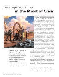
eaction to one or a series of dramatic fires. This led to difficulties concern<strong>in</strong>g trade.One build<strong>in</strong>g product may show good results <strong>in</strong> German tests and be considered as a“fire safe” product. At the same time, the same product may show poor results fromtests <strong>in</strong> UK and is said to be dangerous when <strong>used</strong> <strong>in</strong> build<strong>in</strong>gs. An example of thesedifferences is shown <strong>in</strong> Figure 2.1. <strong>The</strong> figure shows the result of six differentEuropean laboratories, <strong>in</strong> Western Germany, Belgium, Denmark, France, <strong>The</strong>Netherlands and United K<strong>in</strong>gdom, when the same material was subjected to thenational fire tests. <strong>The</strong> reader should especially note the large differences <strong>in</strong> the results<strong>for</strong> materials no. 7, 8 and 18.Grade2422201816141210864200 2 4 6 8 10 12 14 16 18 20 22 24Type of materialWestern GermanyBelguimDenmarkFranceHollandEnglandFigure 2.1 <strong>The</strong> same materials tested <strong>in</strong> six different European fire test laboratories (after /4/). A highgrade <strong>in</strong>dicates good per<strong>for</strong>mance <strong>in</strong> testIn the Construction Products Directive (CPD), described <strong>in</strong> Section 2.1, the secondessential requirement regards fire. <strong>The</strong> CPD is adopted by all member states andthere<strong>for</strong>e becomes national law. In order to harmonize the evaluation systems with<strong>in</strong>EC the EC Pre-normative Research program started <strong>in</strong> 1991, designed to develop asound scientific basis <strong>for</strong> test methods needed to evaluate the fire per<strong>for</strong>mance of allthe materials <strong>in</strong>cluded <strong>in</strong> the CPD. In the end of 1980 and <strong>in</strong> the beg<strong>in</strong>n<strong>in</strong>g of 1990some other research programs, <strong>for</strong> example the EURIFIC and CHARLEMANGEprogram, were carried out <strong>in</strong> order to offer one or more solutions to the problem ofclassification of materials.EUREFIC programLaboratories <strong>in</strong> Denmark, Norway, F<strong>in</strong>land and Sweden launched this program. <strong>The</strong>objective of the program was to show that modern test<strong>in</strong>g techniques could be <strong>used</strong><strong>for</strong> evaluat<strong>in</strong>g the fire behavior of build<strong>in</strong>g materials. <strong>The</strong> program resulted <strong>in</strong> about70 titles of scientific reports and papers. <strong>The</strong>se reports <strong>in</strong>clude <strong>in</strong>structions on how toobta<strong>in</strong> the test data, computer codes on prediction models etc. from the appropriatelaboratories. A bench-scale test called the Cone Calorimeter (ISO 5660) and a fullscaletest method called the Room/Corner (ISO 9705) were <strong>used</strong> <strong>for</strong> test<strong>in</strong>g wall andceil<strong>in</strong>g l<strong>in</strong><strong>in</strong>gs. A proposal <strong>for</strong> classification was presented, based on the time to reachflashover. /5/7
<strong>The</strong> CHARLEMANGE programLaunched <strong>in</strong> 1991 by LNE (France) and LSF (Italy) with participation fromlaboratories <strong>in</strong> Belgium, France and UK. <strong>The</strong> results from this program where <strong>for</strong>example that improvement of the reproducibility and the repeatability <strong>in</strong> the ConeCalorimeter test was suggested and that a data bank was established. <strong>The</strong> program alsoprovided a proposal <strong>for</strong> the classification.<strong>The</strong>se two programs were carried out ma<strong>in</strong>ly to provide a sound technical andscientific solution of the problem. But, when the talk about harmonization <strong>in</strong> Europestarted, three different solutions where identified as possible: a political, a mixedpolitical and technical and a technical solution. <strong>The</strong> political solution <strong>in</strong>tended to keepall the national test methods and make national classes to fit with the new Europeanclasses. This solution was soon abandoned s<strong>in</strong>ce the different national classificationsystems differ on basic pr<strong>in</strong>ciples and the list of complicated situations would havebeen too long. A technical solution were found to be necessary <strong>in</strong> order to obta<strong>in</strong> arobust classification system, but when each member states had their own philosophiesand background this was found difficult to put <strong>in</strong>to practice. <strong>The</strong>re<strong>for</strong>e, the decisionabout the Euroclasses from 1994 is a mixed political and technical solution of theproblem.8
3. <strong>The</strong> EuroclassesIn the development of a harmonized way to test, class and certify products manyquestions have to be considered. For example:• What data do we need <strong>in</strong> order to rank products to their hazard?• How do we get the data?• How do we use the data <strong>in</strong> order to do the rank<strong>in</strong>g?This chapter will try to summarize and analyze the above questions. First the basis <strong>for</strong>the classification will be <strong>in</strong>vestigated. A brief description of the <strong>used</strong> test methods andwhat output data are available from them will follow this part. <strong>The</strong> last part willdescribe how the parameters from the tests are <strong>used</strong> to do the f<strong>in</strong>al classification and<strong>in</strong>vestigate what limits are <strong>used</strong> <strong>for</strong> different classes and why.3.1 IntroductionAround the world today there are many different ways to estimate how dangerous acerta<strong>in</strong> material is <strong>in</strong> reaction to fire and what test methods should be <strong>used</strong>. At thebeg<strong>in</strong>n<strong>in</strong>g of the work with Euroclasses the parameters, mentioned <strong>in</strong> Section 2.2,were set up <strong>for</strong> the rank<strong>in</strong>g of build<strong>in</strong>g products. It was decided that all theseparameters had to be taken <strong>in</strong>to account and the way to the Euroclasses, accepted byall member countries, has been long and difficult. <strong>The</strong>re have been <strong>in</strong>numerablediscussions and debates on which test method to use and how to use the output data torank the products.At the Regulators Group (RG) meet<strong>in</strong>g of June 22 and 23, 1998 it was def<strong>in</strong>itelyagreed that the basis <strong>for</strong> rank<strong>in</strong>g products would be the FIre Growth RAte (FIGRA)<strong>in</strong>dex. This <strong>in</strong>dex is def<strong>in</strong>ed as the peak heat release rate of the fire, exclud<strong>in</strong>g thecontribution of the fire source, divided by the time at which this occurs. It was alsoagreed that the reference scenario is to be the Room/Corner test (ISO 9705) but thema<strong>in</strong> test procedure to be <strong>used</strong> is the S<strong>in</strong>gle Burn<strong>in</strong>g Item (SBI) test /6/. <strong>The</strong>se testmethods will be described <strong>in</strong> Sections 3.3.1 and 3.3.2.This agreement was a big step towards a harmonized system but the member statesagreed that it is not practically possible to rank build<strong>in</strong>g products only after theFIGRA <strong>in</strong>dex. <strong>The</strong>re were more material properties that needed to be taken <strong>in</strong>toaccount than the heat release rate. All build<strong>in</strong>g materials are not combustible andthere<strong>for</strong>e it is not possible to calculate a FIGRA <strong>in</strong>dex. For these k<strong>in</strong>ds of materials itwas necessary to f<strong>in</strong>d another way to describe the reaction to fire such asdeterm<strong>in</strong>ation of the gross calorific potential. However, other materials may produceflam<strong>in</strong>g droplets and particles or produce a lot of smoke, even if the heat release islow. <strong>The</strong>re<strong>for</strong>e, it was also decided to take these <strong>in</strong>to account. <strong>The</strong> conclusion is thatto rank build<strong>in</strong>g materials it was found necessary to complement the FIGRA <strong>in</strong>dexwith other parameters.9
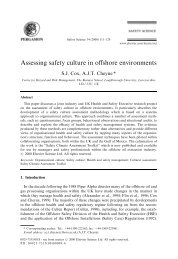
3.2 Basis of classificationBuild<strong>in</strong>g regulations and fire safety-theories throughout the world today are based onthe fact that a small fire is less hazardous than a big and a rapidly grow<strong>in</strong>g fire is moredangerous than a slowly grow<strong>in</strong>g fire. <strong>The</strong>re is no doubt about this. Another hazardouspo<strong>in</strong>t <strong>in</strong> the development of the fire is when flashover is reached. At this time thewhole room is <strong>in</strong>volved <strong>in</strong> the fire and now it also starts to spread outside the room o<strong>for</strong>ig<strong>in</strong>. When the fire has reached this po<strong>in</strong>t the number of deaths <strong>in</strong>creases. Statistics/7/ show an <strong>in</strong>crease by a factor of 3 to 18.However, it is not only the flames that kill <strong>in</strong> a fire. Actually, most people that die <strong>in</strong> afire never are close to it. <strong>The</strong> conclusion of an American study, presented <strong>in</strong> /8/, showsthat smoke <strong>in</strong>halation is the ma<strong>in</strong> cause of fire deaths. <strong>The</strong> smoke <strong>in</strong>halation deathsexceed burn deaths by roughly two to one. This share will be even higher if the fireoccurs <strong>in</strong>side of a build<strong>in</strong>g. Another <strong>in</strong>terest<strong>in</strong>g conclusion from the study is that thenumber of smoke <strong>in</strong>halation deaths is grow<strong>in</strong>g, due to the fact that more and morehazardous products are <strong>used</strong> <strong>in</strong> build<strong>in</strong>gs.Based on the above mentioned facts, the Swedish National Test<strong>in</strong>g and ResearchInstitute (SP) made a proposal. This proposal suggested that the rank<strong>in</strong>g should bebased on fire parameters that describe the maximum size of the fire and the time atwhich this occurs and the smoke production /7/. In other words the rank<strong>in</strong>g should bebased on <strong>in</strong>dices that describe the fire growth rate and smoke production rate. It wasf<strong>in</strong>ally agreed that the classification should be based only on the parameter thatdescribes the fire growth rate and that the smoke production should be a compulsoryadditional declaration.3.3 Test methodsAs mentioned earlier the basis <strong>for</strong> the rank<strong>in</strong>g of build<strong>in</strong>g products will be the FIGRA<strong>in</strong>dex. <strong>The</strong> reference scenario <strong>for</strong> the Euroclass classification will be the Room/Corner(RC) test (ISO 9705) /9/. <strong>The</strong> Room/Corner test will there<strong>for</strong>e be <strong>used</strong> to specify thelevels <strong>for</strong> the classification but to test and classify a product the S<strong>in</strong>gle Burn<strong>in</strong>g Item(SBI) test will be <strong>used</strong>. Other test methods that are necessary to make theclassification complete are the Non-combustibility test, the Gross calorific value testand the Ignitability test. <strong>The</strong>se tests will be described <strong>in</strong> the follow<strong>in</strong>g sections.3.3.1 <strong>The</strong> Room/Corner test (prENISO 9705)<strong>The</strong> Room/Corner test is a large-scale test method <strong>for</strong> measurement of the burn<strong>in</strong>gbehavior of surface l<strong>in</strong><strong>in</strong>g materials <strong>used</strong> <strong>in</strong> build<strong>in</strong>gs. <strong>The</strong> test apparatus consists of asmall compartment with one open door and a gas collection system witch is suppliedwith necessary <strong>in</strong>struments to measure the fire gas properties, see Figure 3.1. /7/10
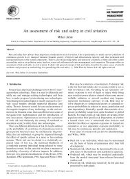
Figure 3.1 <strong>The</strong> Room/Corner test (ISO 9705) /7/<strong>The</strong> l<strong>in</strong><strong>in</strong>g material, which is mounted on three walls and the ceil<strong>in</strong>g, is exposed to afire placed <strong>in</strong> one of the rear corners of the compartment.<strong>The</strong> compartment measures 2.4 m x 2.4 m x 3.6 m (length x height x width) and theopen<strong>in</strong>g has the measure 0.8 m wide and 2.0 m high. <strong>The</strong> ceil<strong>in</strong>g, the floor and thewalls are constructed of non-combustible material. /7/A propane burner is <strong>used</strong> as a ignition source and has a heat output of 100 kW <strong>for</strong> thefirst ten m<strong>in</strong>utes, thereafter the output level is <strong>in</strong>creased to 300 kW <strong>for</strong> another tenm<strong>in</strong>utes. <strong>The</strong> experiment will cont<strong>in</strong>ue until flashover occurs or until twenty m<strong>in</strong>uteshave passed by. <strong>The</strong> criterion of 1000 kW <strong>for</strong> the heat release rate is said to be equalto flashover, def<strong>in</strong>ed as flames com<strong>in</strong>g out through the doorway, if that has notoccurred earlier. /7/<strong>The</strong> output data available from the Room/Corner test are ma<strong>in</strong>ly the time to flashoverand the follow<strong>in</strong>g parameters as a function of time:• Heat Release Rate (HRR)• Smoke Production Rate (SPR)• CO production rate• CO 2 production rate• Oxygen depletion rate.3.3.2 <strong>The</strong> S<strong>in</strong>gle Burn<strong>in</strong>g Item test (prEN)<strong>The</strong> S<strong>in</strong>gle Burn<strong>in</strong>g Item (SBI) test is a new <strong>in</strong>termediate-scale test method developed<strong>in</strong> Europe. <strong>The</strong> SBI test apparatus (trolley, burner, frame, hood and collector), seeFigure 3.2, is placed <strong>in</strong> a small room where the experiment is carried out. /10/11
Figure 3.2. <strong>The</strong> set up <strong>for</strong> the S<strong>in</strong>gle Burn<strong>in</strong>g Item test /11/<strong>The</strong> test room measures 3.0 m x 3.0 m x 2.4 m (length x width x height) andacceptable wall materials are gypsum boards, all stone type build<strong>in</strong>g blocks and fiberboards. Two w<strong>in</strong>dows make it possible to observe the experiment from outside the testroom. <strong>The</strong>re is also an open<strong>in</strong>g <strong>in</strong> one wall to allow the passage of the trolley with thespecimen. A frame <strong>in</strong> which the trolley fits and to which a secondary sandbox burneris fixed supports the gas collection hood. /10/Be<strong>for</strong>e the test starts, two pieces of specimen (495 mm x 1500 mm and 1000 mm x1500 mm respectively) are mounted on a Calcium silicate board and placedperpendicular on the trolley. After that a primary sandbox burner is placed at bottomof the corner between the two parts of specimen. F<strong>in</strong>ally the trolley is placed under thehood <strong>in</strong> the test room. /12/After the trolley has been put <strong>in</strong> place, the specimen will be exposed to a fire from theprimary sandbox burner <strong>for</strong> 20 m<strong>in</strong>utes. <strong>The</strong> heat output from the burner is 30 kW andthe purpose of the secondary sandbox burner is to calibrate the mass flow of propane/12/. <strong>The</strong> measurements will cont<strong>in</strong>ue <strong>for</strong> another 5 m<strong>in</strong>utes after the burner is shutdown.<strong>The</strong> output data that are available from the S<strong>in</strong>gle Burn<strong>in</strong>g Item test are time toignition, flame spread, flam<strong>in</strong>g droplets/particles and the follow<strong>in</strong>g parameters as afunction of time:12
• Heat Release Rate (HRR)• Smoke Production Rate (SPR)• CO 2 production rate• Oxygen depletion rate.Total Heat Release (THR) and the Total Smoke Production (TSP) can be calculatedus<strong>in</strong>g these test results /13/.3.3.3 <strong>The</strong> Non-combustibility test (prENISO 1182)<strong>The</strong> Non-combustibility test is a bench-scale test method <strong>for</strong> determ<strong>in</strong><strong>in</strong>g thecombustibility per<strong>for</strong>mance of homogeneous 1 build<strong>in</strong>g products. If the build<strong>in</strong>gproducts are faced, coated or lam<strong>in</strong>ated the test is not applicable /14/.<strong>The</strong> test apparatus consists of a furnace, a cone-shaped airflow stabilizer, a draughtshield, a specimen holder, an <strong>in</strong>sertion device and thermocouples mounted <strong>in</strong>side thefurnace, see Figure 3.3 /14/.Draughtshield<strong>The</strong>rmocouplesAirflowstabilizerFigure 3.3 General arrangement of the Non-combustibility test /14/<strong>The</strong> furnace consists of a refractory tube surrounded by a heat<strong>in</strong>g coil and an<strong>in</strong>sulation material. <strong>The</strong> tube is 150 mm high with an <strong>in</strong>ternal diameter of 75 mm andmade of an alumni refractory material. To the underside of the furnace, an airflowstabilizer is attached and at the top a draught shield. <strong>The</strong> items mentioned above aremounted on a stand. Further, the furnace is also equipped with a specimen holder andan <strong>in</strong>sert<strong>in</strong>g devise <strong>for</strong> the specimen. /14/<strong>The</strong> test specimen is cyl<strong>in</strong>drical and has a volume of 80 cm 3 , a diameter of 45 mm anda height of 50 mm. <strong>The</strong> test specimen is taken from a sample that is large enough torepresent the product. /14/1 A homogenous product is, accord<strong>in</strong>g to /14/, “Material, consist<strong>in</strong>g of a s<strong>in</strong>gle substance or ahomogeneously dispersed mixture of s<strong>in</strong>gle substances eg metal, concrete, chipboard, m<strong>in</strong>eral wooletc. Homogenous products are not coated, faced or lam<strong>in</strong>ated. <strong>The</strong>y are not composites orassemblies.”13
<strong>The</strong> furnace temperature is 750 o C and normally the test is term<strong>in</strong>ated after 30m<strong>in</strong>utes. However, if temperature equilibrium has not been reached on thethermocouple dur<strong>in</strong>g this time the test will cont<strong>in</strong>ue until the equilibrium has beenreached or until 60 m<strong>in</strong>utes have passed. <strong>The</strong> equilibrium is reached when thevariation <strong>in</strong> temperature does not exceed 2 o C over a period of 10 or 5 m<strong>in</strong>utes (10m<strong>in</strong>utes dur<strong>in</strong>g the first 30 m<strong>in</strong>utes of the test and after that 5 m<strong>in</strong>utes). /14/<strong>The</strong> test results from one test is:• <strong>The</strong> mass loss <strong>in</strong> % of the test specimen• <strong>The</strong> <strong>in</strong>crease of furnace temperature <strong>in</strong> o C over the test period (maximumtemperature m<strong>in</strong>us f<strong>in</strong>al temperature)• <strong>The</strong> duration of susta<strong>in</strong>ed flames <strong>in</strong> seconds.Five specimens are taken and tested from the same material and the result of the entiretest is the average from the five tests.3.3.4 <strong>The</strong> Gross calorific value test (prENISO 1716)<strong>The</strong> prENISO 1716 is a standard that specifies a methods to determ<strong>in</strong>ate the grosscalorific potential under constant volume <strong>for</strong> build<strong>in</strong>g materials /15/.<strong>The</strong> test apparatus consists pr<strong>in</strong>cipally of a calorimetric bomb, calorimeter (jacket,vessel and stirrer), ignition source and temperature measur<strong>in</strong>g devise, see Figure 3.4.<strong>The</strong>rmostat lidIgnition leadsStirrer<strong>The</strong>rmometerCalorimeter can<strong>The</strong>rmostatFigure 3.4 <strong>The</strong> Bomb calorimeter apparatus /16/<strong>The</strong> calorimetric bomb is designed to withstand a pressure of 21 MPa and its <strong>in</strong>nersurface is able to withstand an attack by combustion products. <strong>The</strong> jacket is thermally<strong>in</strong>sulated and also filled with water. /15/14
<strong>The</strong> test specimens are taken from a test sample of a m<strong>in</strong>imum surface area of 0.5 m 2of the product. If the product is homogenous or non-homogenous but cannot bedelam<strong>in</strong>ated, the weight of the specimen is m<strong>in</strong>imum 50 g <strong>for</strong> thick products and 10 g<strong>for</strong> th<strong>in</strong> products. Benzoic acid is added to the specimen to aid the combustion. If theproduct is non-homogenous and can be delam<strong>in</strong>ated, then each component isseparated and treated as mentioned above. /15/If the apparatus is automatic the gross calorific potential will be the output data fromthe test. If the apparatus is manual the gross calorific potential has to be calculated onthe basis of the observed temperature rise us<strong>in</strong>g the follow<strong>in</strong>g <strong>for</strong>mula /16/:PCS = (E * (T m - T i + c) - b) / mwhere:PCSET iT mbcm= gross calorific potential= water equivalent of the calorimeter, the bomb, their accessories and thewater <strong>in</strong>troduced <strong>in</strong>to the bomb, expressed <strong>in</strong> MJ/kg= <strong>in</strong>itial temperature <strong>in</strong> o C= maximum temperature <strong>in</strong> o C= correction expressed <strong>in</strong> kJ required <strong>for</strong> the combustion heat of the <strong>used</strong>fuels= temperature correction expressed <strong>in</strong> K required <strong>for</strong> the exchange of heatwith outside= mass of the test specimen.<strong>The</strong> f<strong>in</strong>al gross calorific potential of a product is the average gross potential valuefrom three tests /16/.3.3.5 Ignitability test (prENISO 11925-2)<strong>The</strong> prENISO 11925-2 is a standard that specifies a method to determ<strong>in</strong>ate theignitability of build<strong>in</strong>g materials by us<strong>in</strong>g a small flame imp<strong>in</strong>gement on a verticaloriented piece of the test product. <strong>The</strong> flame is applied either 40 mm above the bottomedge on the surface centerl<strong>in</strong>e or on the midpo<strong>in</strong>t of the underside edge, see Figure 3.5/17/.SpecimenholderSpecimenSupportBurner baseFigure 3.5 Setup <strong>for</strong> the Ignitability test apparatus15
<strong>The</strong> test apparatus is placed <strong>in</strong> an enclosure made from sta<strong>in</strong>less steel sheets. <strong>The</strong>enclosure is equipped with a glazed door to make it possible to observe the test fromthe outside and to make it possible to enter the enclosure. /17/<strong>The</strong> test specimen measures 250 mm x 90 mm (length x width) but if the material maymelt and shr<strong>in</strong>k away from the flame without be<strong>in</strong>g ignited the specimen mustmeasure 250 mm x 180 mm <strong>in</strong>stead. Six specimens of the same build<strong>in</strong>g product aretested. /17/<strong>The</strong> imp<strong>in</strong>gement flame fuel is propane. Dur<strong>in</strong>g the test the burner is tilted 45 o andgives a flame height of 20 mm when applied to the specimen <strong>for</strong> 15 or 30 seconds. Ifthe flame application time is 15 seconds the test is term<strong>in</strong>ated 20 seconds after theflame has been removed. If the flame application time is 30 seconds the test isterm<strong>in</strong>ated 2 m<strong>in</strong>utes after the flame has been removed or earlier if no ignition isobserved after removal of the flame, the specimen ceases to burn or the flame tipreaches the upper edge of the specimen. /17/<strong>The</strong> output data from the test is:• Flame spread• If ignition occurs• If glow<strong>in</strong>g occurs• Whether or not flam<strong>in</strong>g debris occurs.In the case where the test specimen melts or shr<strong>in</strong>ks when exposed to the flame theonly output data is whether or not flam<strong>in</strong>g debris occurs /17/.3.4 Indices and parameters <strong>for</strong> rank<strong>in</strong>g<strong>The</strong> basis <strong>for</strong> the classification, the test methods and the results from the test methodshave now been described. At this po<strong>in</strong>t we need to answer two questions. ”How do weuse the test results to rank the products?” and “What value of an <strong>in</strong>dex or a parameterwill decide the class limits and give the <strong>in</strong><strong>for</strong>mation that one product is more (or less)hazardous than the other?”<strong>The</strong> parameters and <strong>in</strong>dices that will be described and discussed <strong>in</strong> the follow<strong>in</strong>gsections are:• Heat release rate• Smoke production• Ignition and Flame spread• Gross calorific potential• Non-combustibility• Flam<strong>in</strong>g droplets/particles.<strong>The</strong> values of these parameters and <strong>in</strong>dices, <strong>used</strong> <strong>for</strong> the different classes, are a resultof political compromises and do not have any scientific basis.16
3.4.1 Heat release rateAs mentioned earlier researchers at SP have made an attempt to use the HRR toclassify products, which later was accepted by the other member states <strong>in</strong> EC.<strong>The</strong> FIGRA <strong>in</strong>dex is def<strong>in</strong>ed <strong>in</strong> /7/ as:“the peak heat release rate of the fire, exclud<strong>in</strong>g the contribution of the fire source,divided by the time at which this occurs. Units are kW/s.”As mentioned <strong>in</strong> Section 3.3.1, the gas burner <strong>in</strong> the Room/Corner test will have aheat output of 100 kW <strong>for</strong> the first 10 m<strong>in</strong>utes and then it is <strong>in</strong>creased to 300 kW <strong>for</strong>another ten m<strong>in</strong>utes. This means, <strong>for</strong> example, if the HRR <strong>in</strong> the Room/Corner testreaches 1000 kW and flashover occurs the peak heat release rate from the product canbe either 900 or 700 kW, depend<strong>in</strong>g on when flashover occurs. If, on the other hand,the fire is small (HRR from the tested product is equal or less than 50 kW) the FIGRAshould be considered as zero as the <strong>in</strong>dex might <strong>in</strong>clude uncerta<strong>in</strong>ties.When the ma<strong>in</strong> test procedure <strong>for</strong> the classification of a product is the SBI test, andnot the Room/Corner test, the FIGRA <strong>in</strong>dex must also be def<strong>in</strong>ed <strong>for</strong> the SBI test:“the FIGRA(SBI) is def<strong>in</strong>ed as the maximum value of the quotient of heat release rateand time, multiplied by 1000” /9/.Accord<strong>in</strong>g to /9/ the overall correlation between FIGRA(SBI) and FIGRA(RC) isgood (R 2 = 0.946) 2 , see also Figure 3.6. For products with low values of theFIGRA(RC) and FIGRA(SBI) <strong>in</strong>dices the correlation is somewhat poorer.FIGRA(SBI)400035003000250020001500100050000 10 20 30 40 50 60FIGRA(RC)Figure 3.6 <strong>The</strong> correlation between FIGRA(SBI) and FIGRA(RC)In order to exam<strong>in</strong>e the l<strong>in</strong>k further between the two tests, possible classificationcriteria must be taken <strong>in</strong>to the analysis /9/. As discussed earlier (Section 3.1) theoccurrence of flashover is an important factor, which has to be taken <strong>in</strong>to account <strong>for</strong>the classification. When test<strong>in</strong>g products <strong>in</strong> the same category, <strong>for</strong> example wood2<strong>The</strong> relation between the different FIGRA <strong>in</strong>dices is described us<strong>in</strong>g the coefficient of determ<strong>in</strong>ationR 2 . This coefficient is accord<strong>in</strong>g to /18/ “a measure of how much of the residuals that are expla<strong>in</strong>ed bythe regression model”.17
ased products or gypsum plasterboard, the result will vary from product to product.<strong>The</strong> reason <strong>for</strong> the differences is connected to many parameters, <strong>for</strong> example densityand thermal properties. It is important to keep <strong>in</strong> m<strong>in</strong>d, that at the same time the twoproducts, with<strong>in</strong> the same category, may show a similar burn<strong>in</strong>g behavior althoughthere is a variation. As the FIGRA(RC) <strong>in</strong>dex will decide the classes and their limits itis important that significant differences <strong>in</strong> burn<strong>in</strong>g behavior are shown by a differentclass. It is also important to identify possible categories <strong>in</strong> order to choose the limits <strong>in</strong>a way that borderl<strong>in</strong>e products are avoided. /7/In the result from /7/ three clusters of products are observed, see Figure 3.7. One isseen <strong>for</strong> products with a FIGRA between 0 and 0.6 where no flashover occurs <strong>in</strong> theRoom/Corner test. This agrees with the lowest theoretical value of FIGRA(RC),which is 0.58 (i.e. (1000-300)/(20*60)=700/1200). Another cluster of products isobserved as the FIGRA <strong>in</strong>dex ranges from 0.7 - 1.2. <strong>The</strong>se products reach flashoverwhen the burner effect is <strong>in</strong>creased to 300 kW i.e. after 10 m<strong>in</strong>utes. <strong>The</strong> materials <strong>in</strong>the third cluster reach flashover dur<strong>in</strong>g the first 10 m<strong>in</strong>utes, i.e. when the burneroutput is still 100 kW. <strong>The</strong> lowest identified FIGRA value <strong>for</strong> the tested materials,which belongs to this cluster, is 1.9.FIGRA <strong>in</strong>dex10.90.80.70.60.50.40.30.20.100 5 10 15 20 25 30Rank<strong>in</strong>g numberFIGRA <strong>in</strong>dex1098765432100 10 20 30 40 50 60Rank<strong>in</strong>g numberFigure 3.7 <strong>The</strong> FIGRA <strong>in</strong>dex versus rank<strong>in</strong>g numberIn the work that followed, the limits divid<strong>in</strong>g the clusters were ref<strong>in</strong>ed. For anexample, two important products that often have been representatives of a certa<strong>in</strong> fireclass are plasterboard and wood. <strong>The</strong> plasterboard has a FIGRA(RC) value of 0.16 andthis value is <strong>used</strong> to def<strong>in</strong>e the highest class of the combustible materials, class A2.<strong>The</strong> next class, B, would then range between 0.16 to 0.5. Notice that the earlierdiscussed values of 0.6 and 0.58 are not <strong>used</strong> <strong>for</strong> the borderl<strong>in</strong>e. A conservativeFIGRA(RC) value of 0.5 is <strong>used</strong> to avoid borderl<strong>in</strong>e products /9/.Further, the division between class B and C is at a FIGRA(RC) value of 1.5, whichappears to be very stable with no borderl<strong>in</strong>e products. This value represents the lowesttheoretical FIGRA value <strong>for</strong> products that reaches flashover dur<strong>in</strong>g the first 10m<strong>in</strong>utes of test<strong>in</strong>g.18
<strong>The</strong> last two classes were separated by a FIGRA(RC) value of 7.5 which equals aflashover time at two m<strong>in</strong>utes and is the border <strong>for</strong> natural solid wood. Accord<strong>in</strong>g toFigure 3.7, a FIGRA(RC) value of 7.5 is between two clusters and with no borderl<strong>in</strong>eproducts.This analysis led to the follow<strong>in</strong>g class limits that were decided on the RG meet<strong>in</strong>g 22and 23 June 1998 /19/ presented <strong>in</strong> Table 3.1. Note that the class A from the 1994decision is divided <strong>in</strong>to two classes, A1 and A2.Table 3.1 <strong>Classification</strong> limits <strong>for</strong> the EuroclassesEuroclass Limit value <strong>in</strong> Room/Corner test Burn<strong>in</strong>g behavior <strong>in</strong> referenceFIGRA(RC) (kW/s)scenarioA1 Does not exists, this is the highest -class, non-combustibility.A2 ≤ 0.16 (plaster board) HRR max about 100 kW, noflashover - plaster board or betterB ≤ 0.5 no flashoverC ≤ 1.5 No flashover at 100 kW i.e. flashoveroccurs after 10 m<strong>in</strong>utes (300 kW)D ≤ 7.5 (solid wood) No flashover be<strong>for</strong>e 2 m<strong>in</strong>utes (100kW)E > 7.5 flashover be<strong>for</strong>e 2 m<strong>in</strong>utesFNone of the parameters, peak heat release rate or the total heat release correlates withFIGRA(SBI). <strong>The</strong>re<strong>for</strong>e another def<strong>in</strong>ition of the heat release, the THR, is presentedas an additional <strong>in</strong>dependent parameter, address<strong>in</strong>g a separate fire property. <strong>The</strong> THRis def<strong>in</strong>ed as the total heat released dur<strong>in</strong>g the first 600 seconds of test<strong>in</strong>g. This givestwo properties (FIGRA(SBI) and the THR) that are complementary <strong>in</strong> describ<strong>in</strong>g theburn<strong>in</strong>g behavior. /9/3.4.2 <strong>The</strong> Smoke productionIt is agreed that the parameters to describe the smoke production will be theSMOGRA (SMoke Growth RAte) <strong>in</strong>dex and the Total Smoke Production (TSP). <strong>The</strong>SMOGRA <strong>in</strong>dex <strong>for</strong> the Room/Corner test is def<strong>in</strong>ed by SP /7/ <strong>in</strong> a similar way as theFIGRA <strong>in</strong>dex. <strong>The</strong> def<strong>in</strong>ition is as follows:“the 60 s average of peak smoke production divided by the time at which this occursand multiplied with a factor 1000 to achieve practical values. Units are m 2 /s 2 .”Due to the same reason as discusses above <strong>for</strong> the FIGRA <strong>in</strong>dex, the SMOGRA <strong>in</strong>dexis set to zero if the HRR of the tested product is equal or less than 50 kW.<strong>The</strong> same <strong>in</strong>dex <strong>for</strong> the SBI test, SMOGRA(SBI), is def<strong>in</strong>ed by /12/ as:“<strong>The</strong> maximum value of the function smoke production rate/time multiplied by 10000dur<strong>in</strong>g the whole period of test, i.e. 10000x SPR/t. <strong>The</strong> SPR data is calculated as 60srunn<strong>in</strong>g average to m<strong>in</strong>imise noise.”19
To get a more complete idea how much smoke a given material produces, the totalsmoke production is also <strong>in</strong>cluded. <strong>The</strong> TSP is def<strong>in</strong>ed as the total smoke productiondur<strong>in</strong>g the first 600 seconds of test<strong>in</strong>g.It is also agreed that the smoke production is not a necessary parameter <strong>for</strong> all theclasses A1 to F, see Table 3.1. A product <strong>in</strong> class A1 does produce very little smoke,if any at all, and <strong>for</strong> the classes below D it is not a necessary criteria. However, theclasses between A1 and D do need some levels to rank them accord<strong>in</strong>g to their smokeproduction. It is there<strong>for</strong>e decided that the smoke production of a given material willbe <strong>in</strong>cluded as a compulsory additional declaration besides the other classification.<strong>The</strong> levels <strong>for</strong> the smoke production are /20/:• S1 equals SMOGRA ≤ 30 m 2 /s 2 and TSP 600s ≤ 50 m 2• S2 equals SMOGRA ≤ 180 m 2 /s 2 and TSP 600s ≤ 200 m 2• S3 which is neither S1 nor S2.This mean that a material <strong>in</strong> class B will be supplied with a level of smoke productionsuch as B/S1, B/S2 or B/S3.3.4.3 Ignition and Flame spreadIn order to specify how resistant a certa<strong>in</strong> material is to fire, it was found important tof<strong>in</strong>d out how fast the flame spreads and the time to ignition. For non-combustiblematerial (class A1) there is no need <strong>for</strong> these parameters but <strong>for</strong> the lower classes it isa necessary criteria. As mentioned earlier, there will be two test methods to do this <strong>for</strong>the Euroclasses.One of the output data from the SBI test is lateral flame spread (LFS). To receive acerta<strong>in</strong> class the product will have to fulfill a def<strong>in</strong>ed requirement. For example, if aproduct is to receive class B, the material must have a LFS value lesser than a certa<strong>in</strong>length (the length of the edge of the specimen) when the test is f<strong>in</strong>ished.Two parameters that are obta<strong>in</strong>ed from the Ignitability test when a product is subjectedto direct imp<strong>in</strong>gement of flame, are if ignition occurs and if flame spread occurs. Inthis test the material has to fulfill a requirement of upward flame spread expressed as avalue of length dur<strong>in</strong>g a specified time (F s ). From this value it is possible to rankproducts accord<strong>in</strong>g to their ability to ignite. When the specimen is small and it isexposed to the flame a short time it is not a preferable measurement of the flamespread <strong>for</strong> the product. This requirement is only one among others that is needed <strong>for</strong> amaterial to receive a certa<strong>in</strong> class. For example, a material <strong>in</strong> class B must have an F s -value lesser or equal to 150 mm <strong>in</strong> 60 seconds.3.4.4 Non-combustibility and Gross calorific potential<strong>Materials</strong> <strong>in</strong> the two highest classes (A1 and A2) <strong>in</strong> the Euroclassification do showlittle response, if any at all, to the SBI test. <strong>The</strong>re<strong>for</strong>e, it was found necessary to havesome other criteria than those <strong>for</strong> the more combustible materials <strong>in</strong> the lower classes.<strong>The</strong> test methods mentioned, that are applicable <strong>for</strong> this k<strong>in</strong>d of material, is the Noncombustibletest and the Gross calorific value test. From the first mentioned test it is20
possible to determ<strong>in</strong>e the mass loss, the duration of flames and the temperature changeunder specific conditions. From the latter a material’s gross calorific potential can bedeterm<strong>in</strong>ed. <strong>The</strong>se parameters will there<strong>for</strong>e be <strong>used</strong> to specify products <strong>in</strong> class A1and A2.One reason to use both test methods to determ<strong>in</strong>e material properties, is that they haveearlier been <strong>used</strong> separately <strong>in</strong> different countries and that the correlation betweenthem is poor. Another reason is that the Gross calorific value test allows a highercontent of organic material than the Non-combustibility test. /21/For class A1 it is decided that criteria from both test methods will have to be fulfilledbut <strong>for</strong> class A2 it is decided that a comb<strong>in</strong>ation of the SBI test and one of the twomentioned tests methods is sufficient /22/. For a material <strong>in</strong> class A1, flames are notallowed to susta<strong>in</strong> <strong>for</strong> more than 20 seconds and the material must have a temperaturechange lesser or equal to 30 o C, a mass loss less or equal to 50 % and a gross calorificpotential that does not exceed 2.0 MJ/kg.For a material <strong>in</strong> class A2 there are two alternatives. One is to fulfill the criteria fromthe SBI test and that flames do not susta<strong>in</strong> <strong>for</strong> more than 20 seconds, the temperaturerise is lesser or equal to 50 o C and the mass loss is less or equal to 50 %. <strong>The</strong> otherway is to fulfill the criteria from the SBI test and that the gross calorific potential isless or equal to 4.0 MJ/kg.3.4.5 Flam<strong>in</strong>g droplets/particlesFlam<strong>in</strong>g droplets/particles is one parameters that will be <strong>used</strong> to specify products <strong>in</strong>classes A2, B, C and D. It has been difficult to decide how to <strong>in</strong>clude this parameter <strong>in</strong>the classification.<strong>The</strong> measurement of flam<strong>in</strong>g droplets and particles is based on human observation ofoccurrence dur<strong>in</strong>g the SBI test. It is not easy to evaluate the observations and therehave been some different proposals on how to estimate the occurrence of flam<strong>in</strong>gdroplets or particles. One is simply to have a yes/no criterion and another is to havedifferent levels <strong>for</strong> the amount of occurrence. <strong>The</strong> latter leads on to further questionssuch as “What levels?” and “How to estimate them?” When the f<strong>in</strong>al classificationsystem was announced <strong>in</strong> September 1998, the alternative with different levels waschosen. <strong>The</strong> way to <strong>in</strong>clude this parameter <strong>in</strong> the classification will be to have acompulsory additional declaration beside the other classification, the same way as <strong>for</strong>smoke production.<strong>The</strong> levels <strong>for</strong> the amount of occurrence of flam<strong>in</strong>g droplets or particles are as follows:• D0, which stands <strong>for</strong> no flam<strong>in</strong>g droplets/particles dur<strong>in</strong>g test• D1, which stands <strong>for</strong> no flam<strong>in</strong>g droplets/particles persist<strong>in</strong>g longer than 10seconds• D2, which is neither D0 nor D1. Ignition of the paper <strong>in</strong> the Ignitability test resultsautomatically <strong>in</strong> class D2.This mean that a material <strong>in</strong> class B will be supplied with a level of occurrence offlam<strong>in</strong>g droplets and particles such as B/D0, B/D1 or B/D2.21
3.5 <strong>The</strong> <strong>Classification</strong>Earlier sections have described the test methods, the parameters measured and thecriteria <strong>used</strong> <strong>for</strong> classification. Below, <strong>in</strong> Table 3.2, all the parameters needed tospecify each class are presented, but first some def<strong>in</strong>itions need to be made.”Homogenous products: Material, consist<strong>in</strong>g of a s<strong>in</strong>gle substance or ahomogeneously dispersed mixture of s<strong>in</strong>gle substances eg metal, concrete, chipboard,m<strong>in</strong>eral wool etc. Homogenous products are not coated, faced or lam<strong>in</strong>ated. <strong>The</strong>y arenot composites or assemblies.” /14/“Substantial components: “A material that constitutes a significant part of a nonhomogeneousproduct. A layer with a weight ≥ 1.0 kg/m 2 or a thickness ≥ 1.0 mm isconsidered to be a substantial component.” /23/“Internal non-substantial component: A non-substantial component that <strong>in</strong> its end-usecondition is covered by at least one substantial component at its exposed side” /23/<strong>The</strong> values <strong>in</strong> Table 3.2 is of today, November 1998, and some changes might be done<strong>in</strong> the future.22
Table 3.2 Classes of reaction to fire per<strong>for</strong>mance <strong>for</strong> construction products, exclud<strong>in</strong>g floor<strong>in</strong>gs /20/Class Test method(s) <strong>Classification</strong> criteriaCompulsory additional tests(mean values)A1 Non-combustibility test ∆T ≤ 30 o C and-(prENISO 1182) (1); and ∆m ≤ 50% andt f = 0 (i.e. no susta<strong>in</strong>ed flames)Gross calorific value(prENISO 1716)A2 Non-combustibility test(prENISO 1182) (1); orBCDEGross calorific value(prENISO 1716); andS<strong>in</strong>gle Burn<strong>in</strong>g Item (SBI)testS<strong>in</strong>gle Burn<strong>in</strong>g Item (SBI)test andIgnitability test (prENISO11925-2) (8)Exposure = 30 sS<strong>in</strong>gle Burn<strong>in</strong>g Item (SBI)test andIgnitability test (prENISO11925-2) (8)Exposure = 30 sS<strong>in</strong>gle Burn<strong>in</strong>g Item (SBI)test andIgnitability test (prENISO11925-2) (8)Exposure = 30 sIgnitability test (prENISO11925-2) (8)Exposure = 15 sPCS ≤ 2.0 MJ/kg (1); andPCS ≤ 2.0 MJ/kg (2)PCS ≤ 1.4 MJ/kg (3)PCS ≤ 2.0 MJ/kg (4)∆T ≤ 50 o C and∆m ≤ 50% andt f = 20sPCS ≤ 3.0 MJ/kg (1); andPCS ≤ 4.0 MJ/kg (2)PCS ≤ 4.0 MJ/kg (3)PCS ≤ 3.0 MJ/kg (4)FIGRA(SBI) ≤120 W/s; andLFS< edge of specimen; andTHR 600s ≤ 7.5 MJFIGRA(SBI) ≤ 120W/s; andLFS< edge of specimen; andTHR 600s ≤ 7.5 MJFs ≤ 150 mm with<strong>in</strong> 60 sFIGRA(SBI) ≤ 250 W/s; andLFS< 150 mm with<strong>in</strong> 60 s; andTHR 600s ≤ 15 MJ or deletedFs ≤ 150 mm with<strong>in</strong> 60 sFIGRA(SBI) ≤ 750W/sFs ≤ 150 mm with<strong>in</strong> 60 sFs ≤ 150 mm with<strong>in</strong> 20 s--Smoke production (5) and flam<strong>in</strong>gdroplets, particles and/orcomb<strong>in</strong>ations of these (6)Smoke production (5) and flam<strong>in</strong>gdroplets, particles and/orcomb<strong>in</strong>ations of these (6)Smoke production (5) and flam<strong>in</strong>gdroplets, particles and/orcomb<strong>in</strong>ations of these (6)Smoke production (5) and flam<strong>in</strong>gdroplets, particles and/orcomb<strong>in</strong>ations of these (6)Flam<strong>in</strong>g droplets, particles and/orcomb<strong>in</strong>ation of these (7)F None None No per<strong>for</strong>mance determ<strong>in</strong>ated(1) For homogeneous products and substantial components of non-homogeneous products(2) For any external non-substantial component of non-homogeneous products(3) For any <strong>in</strong>ternal non-substantial components of non-homogeneous products(4) For the product as a whole(5) S1=SMOGRA ≤ 30 m 2 /s and TSP 600 ≤ 50m 2 , S2=SMOGRA ≤ 180 m 2 /s and TSP 600≤ 200 m 2 , S3=not S1 or S2(6) DO = No flam<strong>in</strong>g droplets/particles dur<strong>in</strong>g test, D1 = No flam<strong>in</strong>g droplets/particles persist<strong>in</strong>g longer than 10 secondsD2 = not D1 or D2, ignition of the paper <strong>in</strong> the Ignitability test results <strong>in</strong> class D2(7) Pass = no ignition of paper, Fail = ignition of paper(8) Under end-use condition of surface flame attack and, if appropriate to the end-use condition of the product, edge flame attack23
4. Introduction to the situation <strong>in</strong> JapanIn Japan, the Japanese Build<strong>in</strong>g Standard Law (BSL) together with en<strong>for</strong>cement ordersand m<strong>in</strong>istry notifications regulates everyth<strong>in</strong>g that is connected to build<strong>in</strong>g andconstruction i.e. everyth<strong>in</strong>g from build<strong>in</strong>g <strong>in</strong>spections to how to use the land. S<strong>in</strong>ce1950 these regulations have been the basic regulations to follow. <strong>The</strong> BSL is stated bythe congress (politicians), which is the highest level of legislative central authority.<strong>The</strong> Congress states the fundamental regulations, which are similar to a constitutionand do not give any detailed descriptions of how the requirements are fulfilled. <strong>The</strong>next level of central authority is the Cab<strong>in</strong>et (politicians), which is responsible <strong>for</strong> theen<strong>for</strong>cement orders, which are more detailed than the BSL. One example of theCab<strong>in</strong>et’s responsibility is to state the def<strong>in</strong>itions, which describes the different terms<strong>used</strong> <strong>in</strong> the BSL. In many cases not even the en<strong>for</strong>cement orders are detailed enoughand then it is necessary to use the m<strong>in</strong>istry notifications, which are published by theM<strong>in</strong>istries. A M<strong>in</strong>istry is composed of technicians and is the lowest level of centralauthority. <strong>The</strong> m<strong>in</strong>istry notifications are detailed descriptions <strong>in</strong>clud<strong>in</strong>g <strong>for</strong> exampletest methods and parameters <strong>used</strong> <strong>for</strong> classification.<strong>The</strong> decision-mak<strong>in</strong>g process is often slow <strong>for</strong> the highest level of legislature, butrelatively quick <strong>in</strong> the M<strong>in</strong>istries. This means that it is possible to have a rapiddevelopment concern<strong>in</strong>g test methods and new criteria, which often is useful whenresearch results po<strong>in</strong>t at the necessity of quick changes. <strong>The</strong> hierarchy of the build<strong>in</strong>gregulations is showed <strong>in</strong> Figure 4.1. Beyond the central authorities there are regionalauthorities which states even more detailed rules than the central authorities. Thismeans that all regions <strong>in</strong> Japan do not have the same f<strong>in</strong>al regulations but they do havethe same fundamental regulations. Figure 4.1. <strong>The</strong> hierarchy <strong>for</strong> the central build<strong>in</strong>g regulations <strong>in</strong> Japan4.1 <strong>The</strong> revision of Build<strong>in</strong>g Standard Law<strong>The</strong> BSL have been revised a number of times and the latest occasion was <strong>in</strong> June1998. From 1993 to 1998 work was carried out to develop a new approach <strong>for</strong> the law.This development is today not yet ended <strong>for</strong> all categories of the law, but <strong>in</strong> year 2000all parts are supposed to be taken <strong>in</strong>to practice. <strong>The</strong> aim of the work is to:• rationalize build<strong>in</strong>g procedures• ensure the effective en<strong>for</strong>cement of regulations• rationalize the content of build<strong>in</strong>g regulations.25
Rationalization of build<strong>in</strong>g proceduresIn Japan it was believed that the build<strong>in</strong>g law situation might be prevent<strong>in</strong>g theadm<strong>in</strong>istrative authorities from efficiently per<strong>for</strong>m<strong>in</strong>g build<strong>in</strong>gs confirmations and<strong>in</strong>spections. <strong>The</strong>re<strong>for</strong>e, it was decided that the role shared by public and privateorganizations had to be renewed. <strong>The</strong> aim was to <strong>in</strong>crease the field <strong>for</strong> private and<strong>in</strong>dependent organizations and to make it possible <strong>for</strong> the government authorities toconcentrate more on <strong>in</strong>direct control /24/. Another result from this decision is that thesystem becomes more effective <strong>for</strong> the build<strong>in</strong>g owners, which can obta<strong>in</strong> build<strong>in</strong>gconfirmation and <strong>in</strong>spection services more easily.Ensur<strong>in</strong>g the effective en<strong>for</strong>cement of regulationsBe<strong>for</strong>e June 1998 the build<strong>in</strong>g <strong>in</strong>spections <strong>in</strong> Japan were carried out after the build<strong>in</strong>gwas built. A number of large catastrophes had po<strong>in</strong>ted at the need <strong>for</strong> a system where<strong>in</strong>spections could be undertaken while the build<strong>in</strong>g still was under construction.<strong>The</strong>re<strong>for</strong>e, it was decided that certa<strong>in</strong> adm<strong>in</strong>istrative agencies should decide whichconstruction processes must undergo this <strong>in</strong>spection and the result of this action is thatthe build<strong>in</strong>gs become safer than they are today /24/.To ensure that the regulations are followed properly, it is also important that thesystem allows the public to have access to documents concern<strong>in</strong>g build<strong>in</strong>gconfirmations and <strong>in</strong>spections. To create such a system it was necessary to appo<strong>in</strong>tcerta<strong>in</strong> agencies, which will be required to create and ma<strong>in</strong>ta<strong>in</strong> build<strong>in</strong>g registries /24/.<strong>The</strong> public is then supposed to have access to these registries, which will <strong>in</strong>crease theamount of <strong>in</strong><strong>for</strong>mation about build<strong>in</strong>gs and there<strong>for</strong>e help to protect consumers andimprove the functions of the market.Rationalization of the content of build<strong>in</strong>g regulationsWhen the situation <strong>in</strong> Japan did not allow enough freedom <strong>in</strong> build<strong>in</strong>g design it wasdecided that the regulatory part of the law must be reviewed. <strong>The</strong> build<strong>in</strong>g regulatorysystem had to allow technological progress and to accept the use of materials fromoutside Japan. To make this possible, per<strong>for</strong>mance-based build<strong>in</strong>g regulations had tobe adopted, allow<strong>in</strong>g the use of a wide variety of build<strong>in</strong>g materials, which fulfillcerta<strong>in</strong> per<strong>for</strong>mance requirements /24/. This decision will encourage technologicaldevelopment and the use of more rational techniques. Another result from thisdecision is that there will not be any need to satisfy specification criteria, which alsowill help to <strong>in</strong>crease the design freedom.4.2 <strong>The</strong> development <strong>in</strong> the fire safety areaToday the regulations <strong>in</strong> Japan are prescriptive but allow an eng<strong>in</strong>eer<strong>in</strong>g approach ifthe M<strong>in</strong>istry of Construction permits it. To adopt a per<strong>for</strong>mance based build<strong>in</strong>gregulation and to make it possible to accept material from outside Japan, fire safetystandards have to be developed. New test methods have to be <strong>in</strong>vestigated and thefocus must be directed towards <strong>in</strong>ternationally accepted test methods and build<strong>in</strong>gstandards. To summarize the objectives and goals <strong>for</strong> the future test methods it can besaid /25/, that they shall be:• accepted world wide• applicable <strong>for</strong> any material, structure or equipment26
• able to take <strong>in</strong>to consideration how build<strong>in</strong>g materials, structures and equipmentare <strong>used</strong> <strong>in</strong> practice• able to take the construction processes <strong>in</strong>to account.Establishment of rigorous quality control to ensure stable fire safety per<strong>for</strong>mance <strong>for</strong> along period of time is also important when the use of build<strong>in</strong>g material is considered.<strong>The</strong>re<strong>for</strong>e, a proper quality control procedure is under development so that all certifiedproducts have uni<strong>for</strong>m fire safety per<strong>for</strong>mance. However, when this developmentmight be confus<strong>in</strong>g on the market the law will be changed gradually until year 2000.27
5. <strong>The</strong> Japanese classification system todayToday the classification system of surface l<strong>in</strong><strong>in</strong>g materials <strong>used</strong> <strong>in</strong> build<strong>in</strong>gs is basedon the fact that all materials, which require fire per<strong>for</strong>mance, can be divided <strong>in</strong>to threegroups. <strong>The</strong>se three groups represent the non-combustible materials, quasi noncombustiblematerials and fire retardant materials. Different test methods are <strong>used</strong> todeterm<strong>in</strong>e the material properties <strong>for</strong> materials <strong>in</strong> different groups. Dependent onwhich group the produc<strong>in</strong>g company wants their material to belong to the test methodis chosen. Current prescriptive regulations only regulate the use of materials, whichbelongs to these three groups.5.1. Test methodsToday there are five different test methods <strong>used</strong> <strong>for</strong> the measurement of reaction tofire <strong>for</strong> surface l<strong>in</strong><strong>in</strong>g materials <strong>used</strong> <strong>in</strong> build<strong>in</strong>gs. <strong>The</strong>se tests are:• the Non-combustibility test• the <strong>Surface</strong> test• the Hole test• the Gas toxicity test• the Reduced-scale Model Box (RMB) test.<strong>The</strong> different test methods will be described shortly <strong>in</strong> the follow<strong>in</strong>g sections.5.1.1 <strong>The</strong> Non-combustibility test (JP Notification # 1828)This test procedure is only <strong>used</strong> <strong>for</strong> materials that are considered to be noncombustible.<strong>The</strong> test apparatus and the test procedure <strong>for</strong> the Japanese Noncombustibilitytest are almost the same as <strong>for</strong> the ISO Non-combustibility test, seeSection 3.3.1. <strong>The</strong>re<strong>for</strong>e, only the differences between the two test methods aredescribed <strong>in</strong> this section.<strong>The</strong> Japanese test apparatus is almost identical to the ISO test apparatus. <strong>The</strong> onlysignificant differences are that the Japanese test apparatus has two thermocouples tomeasure the temperature and no <strong>in</strong>sulation around the furnace.<strong>The</strong> only difference, with regards to the test specimen is the shape. <strong>The</strong> shape of thetest specimen is cubical (50 mm x 40 mm x 40 mm) <strong>for</strong> the Japanese test, while it iscyl<strong>in</strong>drical <strong>in</strong> the ISO test.<strong>The</strong> way to measure the temperature difference (∆T) is also slightly different. In theISO Non-combustibility test ∆T is measured as the difference between the highesttemperature peak and the temperature equilibrium. In the Japanese Non-combustibilitytest ∆T is measured as the difference between the highest temperature peak and the<strong>in</strong>itial temperature. <strong>The</strong>re<strong>for</strong>e, the duration of the Japanese test does not need to be aslong as the time <strong>for</strong> the ISO test. <strong>The</strong> duration of the Japanese test is 20 m<strong>in</strong>utescompared to 30-60 m<strong>in</strong>utes <strong>for</strong> the ISO test. <strong>The</strong> difference <strong>in</strong> measurement of ∆T isshown <strong>in</strong> Figure 5.1.29
900850Temperature [C]800750700∆T (Japan)∆T (Europe)650600-3 -0.5 3.5 6 8.5 11 13.5 16 18.5 21 23.5 26 28.5Time [m<strong>in</strong>utes]Figure 5.1 <strong>The</strong> differences <strong>in</strong> measur<strong>in</strong>g ∆T <strong>for</strong> the Japanese and ISO non-combustibility testAnother difference between the test is the output data. While the f<strong>in</strong>al output datafrom the Japanese test is the highest result from three tested specimens the f<strong>in</strong>al outputfrom the ISO test is the average from five tested specimens. In Japan, the onlymeasured parameter is the temperature change of the furnace and not the mass loss ofthe specimen or the duration of susta<strong>in</strong>ed flames, which is given as output from theISO test.5.1.2 <strong>The</strong> <strong>Surface</strong> test (JP Notification # 1828 and 1231) and the Hole test (JPNotification # 1231)<strong>The</strong> <strong>Surface</strong> test<strong>The</strong> <strong>Surface</strong> test is a bench-scale test method <strong>used</strong> to determ<strong>in</strong>e material properties <strong>for</strong>all type of materials. <strong>The</strong> test apparatus consists basically of an open furnace andsmokes chamber, see Figure 5.2.Figure 5.2 Typical set up of the <strong>Surface</strong> test /26/30
<strong>The</strong> furnace is slightly larger than the test specimen and is connected to the smokechamber by a short tube. <strong>The</strong> smoke chamber measures 1.41 m x 1.41 m x 1.0 m(Width x length x height) and is equipped with a stirrer to make the smokehomogenous /27/.<strong>The</strong> test specimen measures 220 mm x 220 mm and the heat<strong>in</strong>g zone measures 180mm x 180 mm. <strong>The</strong> first three m<strong>in</strong>utes the heat<strong>in</strong>g source is a propane burner with aheat output of 0.53 kW and after that a radiant heat source is added with a heat outputof 1.5 kW. <strong>The</strong> total time of the test is either 6 or 10 m<strong>in</strong>utes dependent on whichgroup of material (fire retardant or quasi non-combustible) the tested material belongsto.First a specimen of a reference material (Pearlite board) is tested and after that threespecimens of the actual material. One of the results from each test is the tdθ value,which is a measurement of <strong>in</strong>crease <strong>in</strong> temperature. <strong>The</strong> tdθ value is calculated as thedifference between the temperature-time curve <strong>for</strong> the standard material and the testedmaterial, see Figure 5.3.400350Exhaust temperature [C]30025020015010050tdθReference exhaustStandard exhaust00 60 120 180 240 300 360 420 480 540 600Time [s]Figure 5.3 Def<strong>in</strong>ition of the tdθ value, the thickest l<strong>in</strong>e represents the tested materialAnother result from the test is the smoke production expressed as the <strong>in</strong>crease <strong>in</strong>smoke emission, C A . <strong>The</strong> <strong>in</strong>crease <strong>in</strong> smoke emission is calculated by measur<strong>in</strong>g the<strong>in</strong>tensity of the light transmitted through the smoke be<strong>for</strong>e the test has started (I o ) andat the end of the test (I). When these values are known the C A -value is calculatedus<strong>in</strong>g the follow<strong>in</strong>g expression:C A = 240 x log 10 (I o /I).<strong>The</strong> f<strong>in</strong>al results from the three tests are the highest values of tdθ and C A from thethree tested specimens. For non-combustible and quasi non-combustible materials anadditional parameter is measured, the duration of flames on the surface after theheat<strong>in</strong>g has been <strong>in</strong>terrupted.31
<strong>The</strong> Hole testFor lam<strong>in</strong>ar quasi non-combustible materials the Hole test must be carried out whichis the same test as the <strong>Surface</strong> test but three holes (D = 25 mm) are drilled <strong>in</strong> the testspecimen. <strong>The</strong> aim of this test is to determ<strong>in</strong>e the material properties when all thelayers <strong>in</strong> the material are exposed to heat. <strong>The</strong> output from the Hole test is the same as<strong>for</strong> the <strong>Surface</strong> test.5.1.3 <strong>The</strong> Gas toxicity test (JP Notification # 1231)<strong>The</strong> Gas toxicity test is a bench-scale test method <strong>used</strong> to determ<strong>in</strong>e the occurrence ofhazardous gases when a quasi non-combustible or a fire retardant material is exposedto a heat source. This test was developed <strong>in</strong> 1980 as a result from a number ofmultiple death fires. Most of the people who died <strong>in</strong> those fires died because of thesmoke. <strong>The</strong> aim of the test method is to simulate the situations that can arise <strong>in</strong>evacuation routes and spaces close by the room of fire orig<strong>in</strong>. <strong>The</strong> test apparatusbasically consists of a closed furnace, a mix<strong>in</strong>g box and an animal exposure box,where eight mice are runn<strong>in</strong>g <strong>in</strong> rotary wheels, see Figure 5.4.Figure 5.4 Typical set up of the Gas toxicity test /26/<strong>The</strong> test procedure is almost the same as <strong>for</strong> the <strong>Surface</strong> test. <strong>The</strong> test specimen is firstpreheated with a gas burner <strong>for</strong> three m<strong>in</strong>utes and then a radiant heat source is added.<strong>The</strong> test is first carried out on a specimen made from a reference material, which is32
Red Lauan (a source material <strong>for</strong> plywood). After that, two tests are carried out on thematerial to be tested. <strong>The</strong> duration of the test is 15 m<strong>in</strong>utes.<strong>The</strong> output from each test is the difference <strong>in</strong> time when the mice stop mov<strong>in</strong>g <strong>for</strong> thereference material and the tested material. <strong>The</strong> f<strong>in</strong>al result is largest time differencefrom the two tests.5.1.4 <strong>The</strong> Reduced-scale Model Box (RMB) test (JP Notification #1231)<strong>The</strong> RMB test is 1/3 scale model of the Room/Corner test. <strong>The</strong> test method is <strong>used</strong> todeterm<strong>in</strong>e the behavior of quasi non-combustible material when exposed to fire andwas developed <strong>in</strong> the early eighties. <strong>The</strong> advantage of the RMB test compared to theRoom/Corner test is that it does not need to be term<strong>in</strong>ated immediately after flashoveroccurs and that the cost of each test is far less than <strong>for</strong> the Room/Corner test. <strong>The</strong>actual peak heat release rate and the peak of smoke production often occurs afterflashover and there<strong>for</strong>e the RMB test is convenient <strong>for</strong> measur<strong>in</strong>g post flashoverproperties. <strong>The</strong> test apparatus consists basically of a small compartment, a gascollection system and an ignition source, see Figure 5.5.Figure 5.5 <strong>The</strong> set up <strong>for</strong> the Reduced-scale Model Box test /26/<strong>The</strong> small compartment measures 0.84 m x 0.84 m x 1.68 m (with x height x length),after the surface l<strong>in</strong><strong>in</strong>g material is mounted and the open<strong>in</strong>g is 0.3 m wide and 0.67 mhigh. <strong>The</strong> ceil<strong>in</strong>g, the floor and the walls are made of a non-combustible material.<strong>The</strong> l<strong>in</strong><strong>in</strong>g material is mounted on three walls and the ceil<strong>in</strong>g and is then exposed to anignition source placed <strong>in</strong> one of the rear corners. <strong>The</strong> ignition source consists of a pileof wood cribs (300 mm x 300 mm x 60 mm). <strong>The</strong> duration of the test is 15 m<strong>in</strong>utes.<strong>The</strong> output from the test is the same as <strong>for</strong> the Room/Corner test, i.e.:• Heat release rate (HRR)• Smoke production rate (SPR)• Oxygen depletion rate• CO depletion rate• CO 2 production rate.33
<strong>The</strong> heat release and the maximum heat release rate dur<strong>in</strong>g the test period are theparameters, which are <strong>used</strong> <strong>for</strong> evaluation and classification.5.2 <strong>The</strong> classification and the parameters <strong>used</strong> <strong>for</strong> rank<strong>in</strong>gAs mentioned be<strong>for</strong>e, the different types of surface l<strong>in</strong><strong>in</strong>g materials <strong>used</strong> <strong>in</strong> build<strong>in</strong>gsare divided <strong>in</strong>to three groups <strong>in</strong> Japan. <strong>The</strong>se three groups also represent the differentclasses <strong>in</strong> the classification system and are as follows:• Class I, the non-combustible materials• Class II, the quasi non-combustible materials• Class III, the fire retardant materials.5.2.1 Class I, non-combustible materialsThis is the highest possible class a material can belong to. Earlier this class was only<strong>used</strong> <strong>for</strong> structural components and not <strong>for</strong> surface l<strong>in</strong><strong>in</strong>g materials, but is now also<strong>used</strong> as the latter. <strong>The</strong> test methods <strong>used</strong> <strong>for</strong> materials <strong>in</strong> this class are the Noncombustibilitytest and the <strong>Surface</strong> test. <strong>The</strong> non-combustible materials are of threetypes, legal (fixed by law), general rule (fixed by <strong>in</strong>dustrial standards) and approvedby tests. Examples of non-combustible materials are steel and concrete (legalmaterials), gypsum board (12.5 mm) and calcium silicate board (general rule) andlam<strong>in</strong>ar materials (approved by tests).<strong>The</strong> criteria to be fulfilled <strong>for</strong> a material to belong to this class are:• Non-combustibility test (duration of the test is 20 m<strong>in</strong>utes):- ∆T ≤ 50 o C• <strong>The</strong> <strong>Surface</strong> test (duration of the test is 10 m<strong>in</strong>utes):- tdθ < 0 o C m<strong>in</strong>utes- C A < 30- duration of flames < 30 seconds5.2.2 Class II, quasi non-combustible materialsThis type material is the most common on the Japanese market and there<strong>for</strong>e this isalso the class to which most of the surface l<strong>in</strong><strong>in</strong>g materials on the Japanese marketbelongs to. <strong>The</strong> major test procedures <strong>in</strong> this class are the <strong>Surface</strong> test and the RMBtest. If the results from the <strong>Surface</strong> test are higher than a certa<strong>in</strong> criteria even the Gastoxicity test will be <strong>used</strong> and if the material is lam<strong>in</strong>ated, even the Hole test must be<strong>used</strong>. <strong>The</strong>re are two types of quasi non-combustible materials, general rule andapproved by tests. Examples of the general approved type are gypsum board (9.5 mm)and cement board with wood tips. Examples of the materials approved by tests arenew or lam<strong>in</strong>ated materials.<strong>The</strong> criteria that needs to be fulfilled <strong>for</strong> a material to belong to this class are:• <strong>The</strong> <strong>Surface</strong> test (duration of the test is 10 m<strong>in</strong>utes):34
- tdθ < 100 o C m<strong>in</strong>utes- C A < 60- duration of flames < 60 seconds• RMB test (duration of the test is 15 m<strong>in</strong>utes):- THR < 5 MJ- HRR max < 170 kJ• <strong>The</strong> Hole test (duration of the test is 10 m<strong>in</strong>utes):- tdθ < 150 o C m<strong>in</strong>utes- C A < 60• <strong>The</strong> Gas toxicity test (duration of the test is 15 m<strong>in</strong>utes):- Time until the mice stop mov<strong>in</strong>g (the test specimen must have atime that is equal or less than the time <strong>for</strong> the reference material)5.2.3 Class III, fire retardant materials<strong>The</strong> fire retardant materials are seldom <strong>used</strong> <strong>in</strong> practice when there are few areas <strong>in</strong>which they are allowed accord<strong>in</strong>g to the regulations. <strong>The</strong>re are two types of fireretardant materials, general and approved by tests. Examples of the general approvedtype are fire retardant plywood and alum<strong>in</strong>um plate. Examples of the materialsapproved by test are new or lam<strong>in</strong>ated materials.• <strong>The</strong> <strong>Surface</strong> test (duration of the test is 6 m<strong>in</strong>utes):- tdθ < 350 o C m<strong>in</strong>utes- C A < 120• <strong>The</strong> Gas toxicity test (duration of the test is 15 m<strong>in</strong>utes):- Time until the mice stop mov<strong>in</strong>g (the test specimen must have atime that is equal or less than the time <strong>for</strong> the reference material)35
5.2.4 <strong>The</strong> classificationEarlier sections have described the test methods, the parameters measured and thecriteria <strong>for</strong> each class of material. Table 5.1 summarizes the classification system.Table 5.1 Classes of reaction to fire per<strong>for</strong>mance <strong>for</strong> surface l<strong>in</strong><strong>in</strong>g materials <strong>used</strong> <strong>in</strong> build<strong>in</strong>gsClass Test methods <strong>Classification</strong> criteriaClass INon-combustibility test (JPNotification # 1828)<strong>Surface</strong> test (JP Notification #1828 and 1231)Class II <strong>Surface</strong> test (JP Notification #1828 and 1231)Hole test (JP Notification # 1231)RMB test (JP Notification #1231)Gas toxicity test (JP Notification# 1231)Class III <strong>Surface</strong> test (JP Notification #1828 and 1231)Gas toxicity test (JP Notification#1231)∆T ≤ 50 o Ctdθ < 0 o C m<strong>in</strong>utesC A < 30tdθ < 0 o C m<strong>in</strong>utesC A < 30duration of flames < 30 secondstdθ < 100 o C m<strong>in</strong>utesC A < 60duration of flames < 60 secondstdθ < 150 o C m<strong>in</strong>utesC A < 60THR < 5 MJHRR max < 170 kJTime to the mice stop mov<strong>in</strong>g (thetest specimen must have a time thatis equal or less than the time <strong>for</strong> thereference material)tdθ < 350 o C m<strong>in</strong>utesC A < 120Time until the mice stop mov<strong>in</strong>g(the test specimen must have a timethat is equal or less than the time <strong>for</strong>the reference material)36
6. Proposal <strong>for</strong> a new Japanese classification systemIn order to meet with per<strong>for</strong>mance based build<strong>in</strong>g regulations and <strong>in</strong>ternationaldemands <strong>for</strong> harmonization the M<strong>in</strong>istry of Construction (MOC) started a five yearresearch and development program, the So-pro program, <strong>in</strong> 1993. <strong>The</strong> So-proprogram, "Development of Assessment Methods <strong>for</strong> Fire Safety <strong>in</strong> Build<strong>in</strong>gs", is acomprehensive research program encapsulat<strong>in</strong>g a large number of research projects <strong>for</strong>technical development. It <strong>in</strong>cludes an evaluation of per<strong>for</strong>mance based regulations anddevelopment of a new test<strong>in</strong>g and evaluation system <strong>for</strong> build<strong>in</strong>g materials andcomponents.<strong>The</strong> objectives concern<strong>in</strong>g build<strong>in</strong>g materials can be summarized as:• specification of fire safety per<strong>for</strong>mance of materials• <strong>in</strong>ternational harmonization of fire test<strong>in</strong>g methods• revision of fire test<strong>in</strong>g methods <strong>in</strong> Japan.<strong>The</strong> f<strong>in</strong>al decision on the new Japanese classification system is not yet taken.<strong>The</strong>re<strong>for</strong>e, this chapter will describe the current situation and the proposals, which arebe<strong>in</strong>g considered, and there might be some changes <strong>in</strong> the future.6.1 Specification of fire safety per<strong>for</strong>mance of materials<strong>The</strong> specification of fire safety per<strong>for</strong>mance required <strong>for</strong> materials is divided <strong>in</strong>to fourtypes: structures, build<strong>in</strong>g equipment, exterior l<strong>in</strong><strong>in</strong>gs and <strong>in</strong>terior l<strong>in</strong><strong>in</strong>gs. This reportma<strong>in</strong>ly deals with <strong>in</strong>terior l<strong>in</strong><strong>in</strong>gs so this section will focus on such materials. Wheresurface l<strong>in</strong><strong>in</strong>g materials are concerned the objective is to:• prevent fire outbreak• ensure life safety <strong>for</strong> occupants, <strong>in</strong> the room of fire orig<strong>in</strong>• ensure the fire safety <strong>in</strong> evacuation routes and spaces near by the room of fireorig<strong>in</strong>.Prevent fire outbreakIn order to meet with the objective <strong>for</strong> surface l<strong>in</strong><strong>in</strong>g materials, parameters have to bespecified to describe the fire safety per<strong>for</strong>mance. In the So-pro program it wasconcluded that a fire seldom starts on the l<strong>in</strong><strong>in</strong>g material but if <strong>for</strong> example a sofa, TVor kitchen appliance ignites, the <strong>in</strong>terior l<strong>in</strong><strong>in</strong>g plays an important role <strong>for</strong> the firespread and the risk of a fully developed room fire. <strong>The</strong>re<strong>for</strong>e, if the ignitability of thel<strong>in</strong><strong>in</strong>g material could be reduced the total fire risk is also reduced. <strong>The</strong>re<strong>for</strong>e, theignitability was considered to be the key parameter to prevent fire outbreak. /28/Ensure life safety <strong>for</strong> occupants, <strong>in</strong> the room of fire orig<strong>in</strong>A safe evacuation is characterized by the fact that people are able to get out of thebuild<strong>in</strong>g be<strong>for</strong>e critical conditions <strong>for</strong> smoke, temperature or visibility occur. In mostoccupancies it is not difficult to complete the evacuation be<strong>for</strong>e these criticalconditions occur. However, the evacuation is relatively often <strong>in</strong>fluenced by irrationaldecisions and behavior and <strong>in</strong> occupancies <strong>for</strong> health care, disabled people or elderly it37
may be difficult to ensure a safe evacuation. <strong>The</strong>re<strong>for</strong>e, to ensure life safety <strong>for</strong> theoccupants <strong>in</strong> the room of fire orig<strong>in</strong> the key parameter could be control of thecombustibility. /28/Ensure the fire safety <strong>in</strong> evacuation routes and spaces near by the room of fire orig<strong>in</strong>As described <strong>in</strong> Section 3.1 most fire deaths are due to the <strong>in</strong>halation of smoke andoften occur far from the fire itself. To ensure fire safety <strong>in</strong> evacuation routes andspaces near the room of fire orig<strong>in</strong> it was concluded that it is more reasonable to usesmoke control design, rather than control of surface l<strong>in</strong><strong>in</strong>g material. However, thesmoke control design relies on parameters like optical density and gas toxicity, whichhave to be determ<strong>in</strong>ed by test<strong>in</strong>g. <strong>The</strong> fire load <strong>in</strong> escape routes, such as combustiblefurniture, is often already controlled but it is also important to control the reaction tofire of the surface l<strong>in</strong><strong>in</strong>g material. This is especially important <strong>in</strong> occupancies wherefast evacuation is not expected. /28/When flashover occurs there is a sudden and dramatic <strong>in</strong>crease <strong>in</strong> the production ofcarbon monoxide. <strong>The</strong> escapes routes and spaces near by the room of fire orig<strong>in</strong> arethere<strong>for</strong>e most affected when the fire reaches this stage and to ensure life safety it wasfound necessary to prevent flashover. One result from the So-pro program is that the<strong>in</strong>teraction between l<strong>in</strong><strong>in</strong>g materials <strong>in</strong> ceil<strong>in</strong>g and walls plays an important role <strong>in</strong> thefire growth. If a non-combustible material is mounted <strong>in</strong> the ceil<strong>in</strong>g, <strong>in</strong> theRoom/Corner test, the time to flashover will <strong>in</strong>crease with almost 10 m<strong>in</strong>utes,compared to if a combustible material was mounted <strong>in</strong> the ceil<strong>in</strong>g /28/. Based on thisresult it might be said that mount<strong>in</strong>g of non-combustible material <strong>in</strong> the ceil<strong>in</strong>g canprevent flashover <strong>for</strong> a number of cases where combustible materials are mounted onthe walls. <strong>The</strong>re<strong>for</strong>e, a design solution might <strong>in</strong>clude the use of combustible materialsbut still have an evacuation time that is enough <strong>for</strong> most common build<strong>in</strong>gs.All the key parameters, except the ignitability, and the production of carbon monoxidedo have a close connection to the heat release (HRR) /28/. <strong>The</strong>re<strong>for</strong>e, it was decidedthat the most important parameter to measure is the HRR. But, even if the smokeproduction was found to have a close connection to the HRR it has been discussed ifthis relation is good enough. <strong>The</strong> current situation is that the smoke production alsowill be <strong>in</strong>cluded <strong>in</strong> the classification system. When the ignitability not are connectedto the HRR, it was decided that this parameter also had to be <strong>in</strong>cluded <strong>in</strong> theclassification.6.2 International harmonization and revision of fire test<strong>in</strong>g methodsIn order to meet with the objectives of <strong>in</strong>ternational harmonization and revision of firetest<strong>in</strong>g methods concern<strong>in</strong>g build<strong>in</strong>g materials, eleven test methods <strong>in</strong>clud<strong>in</strong>g fiveJapanese tests and six ISO tests were studied and compared. <strong>The</strong> five Japanese testswere the Non-combustibility test, the <strong>Surface</strong> test, the Hole test, the Gas toxicity testand the Reduced-scale Model Box test. <strong>The</strong> six ISO tests were the Non-combustibilitytest (ISO 1182), the Ignitability test (ISO 5667), the Ignition and lateral flame spreadtest (ISO 5658), the S<strong>in</strong>gle chamber test (ISO 5659), the Cone Calorimeter test (ISO5660) and the Room/Corner test (ISO 9705).38
6.2.1 Conclusions about the fire test<strong>in</strong>g methodsAs discussed <strong>in</strong> Section 6.1 the most important parameters that have to be describedby the <strong>used</strong> test method are the ignitability and the fire growth. <strong>The</strong> So-pro programfound that if little flame spread occurs <strong>in</strong> the fully developed fire stage, the mostreasonable test method is the ISO 1182 or Japanese Non-combustibility test. To meetwith the objective of <strong>in</strong>ternational harmonization and based on the good correlationbetween the two tests the ISO version of the Non-combustibility test was chosen. Iflittle flame spread occurs <strong>in</strong> the <strong>in</strong>itial fire stage or flame spread is controlled <strong>in</strong> theroom of fire orig<strong>in</strong>, and a safe evacuation is possible the most reasonable test methodwas found to be the ISO 9705 Room/Corner test.Based on these conclusions it was decided that the Room/Corner test was to be thereference scenario <strong>for</strong> the classification. However, to always use the Room/Corner testwould be very expensive and there<strong>for</strong>e it was decided that a bench-scale test, thatcorrelates well with the reference scenario, had to be found. <strong>The</strong> first bench-scale testto be <strong>in</strong>vestigated was the RMB test.<strong>The</strong> RMB test has been modified and has changed the heat source from a pile of woodcribs to a propane burner and is now a proposed ISO standard. <strong>The</strong> experiments withthis modified RMB test, from now on simply referred to as the Model Box (MB) test,and the Room/Corner test has this far not succeeded <strong>in</strong> f<strong>in</strong>d<strong>in</strong>g a good correlationbetween the heat release from the two tests. <strong>The</strong>re<strong>for</strong>e, the MB test will probably onlybe <strong>used</strong> to measure the smoke production, when it is convenient to measure postflashover properties, see Section 5.1.4.<strong>The</strong> most favorable test to determ<strong>in</strong>e the smoke toxicity <strong>for</strong> burn<strong>in</strong>g materials wasfound to be the Gas toxicity test. <strong>The</strong>re are also plans to propose this test to ISO and <strong>in</strong>order to do this the mice probably has to be replaced by an apparatus that measures thegas properties. It is today not yet decided how to use this test <strong>for</strong> classification but itwill probably be <strong>used</strong> <strong>in</strong> comb<strong>in</strong>ation with the MB test.<strong>The</strong> test procedure that shows best relationship to the heat release from the referencescenario was found to be the Cone Calorimeter. With the output from the ConeCalorimeter it is possible to determ<strong>in</strong>e which materials that go to flashover <strong>in</strong> thereference scenario and the time at which this occurs. By plott<strong>in</strong>g the ignitiontemperature divided by a constant as a function of the peak heat release rate it ispossible to identify the materials behavior <strong>in</strong> the Room/Corner test. This relationshipwas developed and solved analytically by Thomas and Karlsson /29/ and laterrepresented graphically by Kokkala and Baroudi /30/, which is shown <strong>in</strong> Figure 6.1.<strong>The</strong> output from the Cone Calorimeter can also be <strong>used</strong> <strong>for</strong> per<strong>for</strong>mance based designsolutions and an eng<strong>in</strong>eer<strong>in</strong>g approach. Based on these facts it was decided that theCone Calorimeter test was go<strong>in</strong>g to be the ma<strong>in</strong> test procedure <strong>for</strong> surface l<strong>in</strong><strong>in</strong>gmaterials. However, the results from the Cone Calorimeter do not always show a goodrelation to the reference scenario. <strong>The</strong>re<strong>for</strong>e, it was decided that the Room/Corner testwould be <strong>used</strong> <strong>for</strong> materials where the result from the Cone Calorimeter po<strong>in</strong>ts at apoor relation. A short description of the Cone Calorimeter is presented <strong>in</strong> the nextsection.39
Figure 6.1 <strong>The</strong> graph, which determ<strong>in</strong>e the flame spread acceleration <strong>for</strong> a material tested <strong>in</strong> the ConeCalorimeter /31/<strong>The</strong> output from the Cone Calorimeter test can, as mentioned, be <strong>used</strong> <strong>for</strong>per<strong>for</strong>mance based design but many calculation and computer programs uses theoutput from the American or International version of the Lateral Ignition and FlameSpread test, LIFT. <strong>The</strong>re<strong>for</strong>e, it is not yet decided if the Cone Calorimeter test will beaccompanied by one of these tests.6.2.2 <strong>The</strong> Cone Calorimeter test (ISO 5660)<strong>The</strong> Cone Calorimeter test is a bench-scale test <strong>used</strong> to determ<strong>in</strong>e the reaction to fire<strong>for</strong> surface l<strong>in</strong><strong>in</strong>g materials <strong>used</strong> <strong>in</strong> build<strong>in</strong>gs. <strong>The</strong> test apparatus consist basically ofan electric heater, an ignition source and a gas collection system, see Figure 6.2.Figure 6.2 Typical set up <strong>for</strong> the Cone Calorimeter test /32/40
<strong>The</strong> test specimen measures 100 mm x 100 mm and has a thickness between 6 mmand 50 mm. Dur<strong>in</strong>g the test the specimen is mounted horizontally on a low heat loss<strong>in</strong>sulat<strong>in</strong>g ceramic material. <strong>The</strong> orientation of the specimen can also be vertical, butthis is most often <strong>used</strong> only <strong>for</strong> exploratory studies. /32/After the test specimen has been mounted and placed <strong>in</strong> the right position, it isexposed to a heat flux from the electric heater. <strong>The</strong> output from the heater can bechosen <strong>in</strong> the range of 0–100 kW/m 2 , but usually the heat output is <strong>in</strong> the range of 25–75 kW/m 2 /31/. When the mixture of gases above the test specimen is higher than thelower flammability limit, it is ignited by an electric heat source. <strong>The</strong> duration of thetest is normally 10 m<strong>in</strong>utes but is not fixed and can vary depend<strong>in</strong>g on the material.<strong>The</strong> results from each test are:• Time to ignition• Mass loss rate• Heat release rate.If a gas analyzer is added to the test equipment it is also possible to take theproduction of smoke and toxic gases <strong>in</strong>to account.6.3 Design solutions <strong>for</strong> surface l<strong>in</strong><strong>in</strong>g fires<strong>The</strong> proposal from the So-pro program today <strong>in</strong>cludes three different routes of designsolutions, A, B and C. Route A is the most conservative of the three and is meant tobe <strong>used</strong> <strong>in</strong> cases where a prescriptive approach is favorable. To make it possible toaccept "new" solutions as large structures made of wood or designs that can not bedescribed us<strong>in</strong>g route A, a second route can be chosen, route B. This route is aper<strong>for</strong>mance based approach which is based on calculation methods and criteria given<strong>in</strong> law. If routes A or B are not applicable, there will be an opportunity to chose a thirdapproach, route C. When choos<strong>in</strong>g this route it is possible to use other calculationmethods than those given by law. <strong>The</strong> only regulation is that the solutions have to beapproved by experts. <strong>The</strong> proposed routes are not f<strong>in</strong>ally decided and there<strong>for</strong>e thissection will describe the current situation but there might be some changes <strong>in</strong> thefuture. In Figure 6.3 the three different proposals <strong>for</strong> design solutions are illustrated. Figure 6.3 Illustration of the three different approaches, route A, B and C41
6.3.1 <strong>The</strong> Conservative approach, Route ARoute A is, as described above, the most conservative approach. Here the designerchooses an approach with prescriptive requirements, with materials tested and classedby methods given by law. Due to the good correlation to the Room/Corner test, theCone Calorimeter will be the ma<strong>in</strong> test procedure but the MB test or the Gas toxicitytest will probably accompany this test. Some materials might even be tested <strong>in</strong> the ISONon-combustibility test. <strong>The</strong> classification will be based on the Room/Corner test andwill most probably <strong>in</strong>clude three different classes:• Class 1, where materials not reach flashover• Class 2, where materials reach flashover after a time longer than 10 m<strong>in</strong>utes• Class 3, where materials reach flashover with<strong>in</strong> 10 m<strong>in</strong>utes.<strong>The</strong>se classes will be very similar to the ones <strong>used</strong> today. <strong>The</strong> new classes can be saidto represent the non-combustible materials (Class I), the quasi non-combustiblematerials (Class 2) and fire retardant materials together with combustible materials(Class 3).For structural materials there will also be a non-combustible class <strong>for</strong> which the ma<strong>in</strong>test method is the ISO Non-combustibility test. If a material from this class is <strong>used</strong> as<strong>in</strong>terior l<strong>in</strong><strong>in</strong>g there will be no need to use the Cone Calorimeter test to determ<strong>in</strong>ematerial properties. If a material fulfill the requirements <strong>for</strong> the structural noncombustibleclass it is certa<strong>in</strong> that it will fulfill the requirements from the ConeCalorimeter <strong>for</strong> material <strong>in</strong> Class 1. <strong>The</strong>re<strong>for</strong>e, a material <strong>in</strong> Class 1 can be tested <strong>in</strong>either the Non-combustibility test or <strong>in</strong> the Cone Calorimeter test, which will be thema<strong>in</strong> test method. However, there are also two other proposals <strong>for</strong> the class limits.A second proposal <strong>for</strong> class limits suggests that Class 3 <strong>in</strong> the most probable proposalbe divided <strong>in</strong>to two classes, Class 3.1 and Class 3.2. <strong>Materials</strong> <strong>in</strong> class 3.1 do notreach flashover be<strong>for</strong>e 5 m<strong>in</strong>utes of test<strong>in</strong>g and materials <strong>in</strong> Class 3.2 reach flashoverbe<strong>for</strong>e five m<strong>in</strong>utes of test<strong>in</strong>g, <strong>in</strong> the Room/Corner test. This proposal leads to aclassification, where the fire retardant and the combustible materials are divided <strong>in</strong>totwo different classes.<strong>The</strong>re is also a third proposal <strong>for</strong> class limits, which suggests that Class 2 <strong>in</strong> the firstmentioned proposal be divided <strong>in</strong>to two classes, Class 2.1 and 2.2. Class 2.1 wouldrepresent materials that reach flashover dur<strong>in</strong>g the last 10 m<strong>in</strong>utes of test<strong>in</strong>g but doesthen decrease so the fire spread is limited. Class 2.2 represents materials, which reachflashover dur<strong>in</strong>g the last 10 m<strong>in</strong>utes of test<strong>in</strong>g and <strong>for</strong> which the fire <strong>in</strong>tensity always<strong>in</strong>creases. However, it is not yet decided how to identify these class limits with theoutput data from the cone calorimeter. It is most likely that the first alternative <strong>for</strong>class limits will be <strong>used</strong> and there<strong>for</strong>e that classification will be <strong>used</strong> as the base <strong>for</strong>further studies and comparisons <strong>in</strong> this report.<strong>The</strong> mentioned class limits are based on a study of evacuation plann<strong>in</strong>g /33/. Ifflashover is consider as the critical po<strong>in</strong>t <strong>for</strong> evacuation and that no further evacuationcan be per<strong>for</strong>med after flashover has occurred this can easily be <strong>used</strong> <strong>for</strong> design. Foran example could materials <strong>in</strong> Class 1 be <strong>used</strong> <strong>for</strong> surface l<strong>in</strong><strong>in</strong>gs <strong>in</strong> build<strong>in</strong>gs likehospitals or <strong>for</strong> elderly people where a quick evacuation not can be expected.42
<strong>Materials</strong> <strong>in</strong> Class 2 and Class 3 would then be more suited <strong>for</strong> use <strong>in</strong> build<strong>in</strong>gs wherea quick evacuation can be expected.6.3.2 <strong>The</strong> Per<strong>for</strong>mance Based approach, Route BIn this approach, the <strong>in</strong>tention is that a room fire model will be <strong>used</strong> to fulfill certa<strong>in</strong>requirements given by law. Also the accepted room fire models and test methods will<strong>for</strong> this route be given by law. In order to <strong>in</strong>troduce room fire models <strong>in</strong> practice, theSo-pro program <strong>in</strong>vited authors of "open" room fire models to co-operate onvalidation by a third person and improvement of their models. Prof. J. Qu<strong>in</strong>tiere,Maryland University, and Dr. B. Karlsson, Lund University accepted the <strong>in</strong>vitation.This project is still under development but has led to some calculation methods tosimulate fire growth behavior <strong>in</strong> the Room/Corner test /34/. <strong>The</strong> methods is based onthe work done by Karlsson /31/ and Qu<strong>in</strong>tiere /35/ and shows good agreement with theheat release rate from experiments <strong>in</strong> the Room/Corner test. <strong>The</strong>re is especially a goodagreement <strong>for</strong> wooden based products and when most materials <strong>used</strong> <strong>for</strong> l<strong>in</strong><strong>in</strong>g arewooden based products this is a hopeful result.At least two problems are under <strong>in</strong>vestigation be<strong>for</strong>e the calculation models can be<strong>used</strong> <strong>in</strong> practice. First, the assessment methods on material properties, such as thermal<strong>in</strong>ertia and ignition temperature, have to be established. <strong>The</strong>se necessary parameters,<strong>used</strong> as <strong>in</strong>put to the models, are obta<strong>in</strong>ed from either the Cone Calorimeter test (ISO5560) or the LIFT. S<strong>in</strong>ce the number of LIFT apparatuses is very limited <strong>in</strong> Japan, the<strong>in</strong>tention is to establish the assessment method by only us<strong>in</strong>g the Cone Calorimetertest. Second, the present calculation models have to be modified to describe not onlythe Room/Corner test configuration but also compartments with a larger area and/orhigher ceil<strong>in</strong>g height. When the work with this computer program is completed, it willbe recommended as a tool <strong>for</strong> route B <strong>in</strong> the law.6.3.3 Route CWhile route A is the descriptive approach and B a per<strong>for</strong>mance based, route C is theapproach with largest freedom <strong>for</strong> the designer. Here, the designer is free to use anytest methods or calculation models <strong>for</strong> the basis of the design. <strong>The</strong> only regulation isthat the test methods and calculation procedures have to be approved by experts.<strong>The</strong>re will probably be a number of suggestions <strong>for</strong> calculation procedures, but thedesigner is free to choose any available calculation model and test method. <strong>The</strong>requirements <strong>for</strong> this route have not been <strong>for</strong>mulated yet but will probably be similarto those <strong>for</strong> route B. <strong>The</strong> discussions are still vague and noth<strong>in</strong>g is decided today but itis concluded that this approach could be very useful <strong>in</strong> the future with other conditionsthan today.43
7. Possibilities to a direct l<strong>in</strong>k between the systemsWhen now both the Japanese and the European classification systems have beendescribed it can be questioned if there are any possibilities to l<strong>in</strong>k them together. <strong>The</strong>first question that must be answered is if there are any possibilities to f<strong>in</strong>d a direct l<strong>in</strong>kbetween the two classification systems. <strong>The</strong>re<strong>for</strong>e, this question will be discussed andexam<strong>in</strong>ed closer <strong>in</strong> this chapter. <strong>The</strong> comparison of the systems is made between boththe Japanese system today and the Euroclasses and the proposed Japanese system andthe Euroclasses. In this report, a direct l<strong>in</strong>k means that it is possible to translate oneclass from one system <strong>in</strong>to a specific class <strong>in</strong> the other system without any necessaryadditional tests or advanced calculations. This might be done one or both ways but itis still considered to be a direct l<strong>in</strong>k <strong>in</strong> this report, see Figure 7.1. ( ) Figure 7.1 <strong>The</strong> def<strong>in</strong>ition of direct l<strong>in</strong>ks between the systems7.1 <strong>The</strong> Euroclasses and the Japanese system todayToday’s classification system <strong>in</strong> Japan, <strong>for</strong> surface l<strong>in</strong><strong>in</strong>g material, will only be <strong>in</strong> useuntil June year 2000. After this, the new proposed Japanese system will be taken <strong>in</strong>topractice and there<strong>for</strong>e, the comparison <strong>in</strong> this section is only a brief study ofsimilarities and differences between the Japanese system and the Euroclasses. Thiscomparison might still be of some importance when try<strong>in</strong>g to understand the situation<strong>in</strong> Japan today.As the reader probably has observed, there are some major differences between theEuroclasses and the Japanese classification system today. <strong>The</strong> most obvious are thedifferences <strong>in</strong> the test procedures, the parameters <strong>used</strong> <strong>for</strong> the rank<strong>in</strong>g, and the numberof classes, see Table 7.1. Another difference that might be important <strong>for</strong> thecomparison is that the Euroclasses are based on a reference scenario, theRoom/Corner test, s<strong>in</strong>ce the Japanese system is not based on a reference scenario.45
Table 7.1 <strong>The</strong> different test methods and parameters <strong>used</strong> <strong>for</strong> classification <strong>in</strong> Europe and Japan todayEuropean test methods and Japanese test methods andparametersparameters , todayReference scenario Room/Corner test (ISO 9705) No reference scenarioNon-combustibilitytestsMa<strong>in</strong> andadditional testsNon-combustibility test (ISO 1182)Parameters: ∆T, ∆m, t fGross calorific value test (ISO1716)Parameter: PCSS<strong>in</strong>gle Burn<strong>in</strong>g Item (SBI) test(prEN)Parameters: FIGRA(SBI), LFS, THR 600s ,smoke and flam<strong>in</strong>gdroplets/particlesIgnitability test (ISO11925-2)Parameter: FsNon-combustibility test (JPNotification # 1828 )Parameter: ∆T<strong>Surface</strong> test (JP Notification 1828and 1231)Parameters: tdθ, C A , duration of flames<strong>Surface</strong> test (JP Notification 1828and 1231)Parameters: tdθ, C A , duration of flamesHole test (JP Notification 1231)Parameters: tdθ, C AReduced-scale Model Box test (JPNotification # 1231)Parameters: THR, HRR maxGas toxicity test (JP Notification1231)Parameter: Time to the mice stop mov<strong>in</strong>gTo f<strong>in</strong>d a direct l<strong>in</strong>k there is need <strong>for</strong> research on the correlation between theparameters available from the <strong>used</strong> test methods. <strong>The</strong> fact that very few researchprojects have been carried out <strong>in</strong> this area complicates the comparison. <strong>The</strong> results<strong>used</strong> <strong>in</strong> this report are ma<strong>in</strong>ly from projects <strong>in</strong> the So-pro program, which makes itpossible to state some conclusion on a possible direct l<strong>in</strong>k.7.1.1 Non-combustible materialsOne of the similarities of the classification systems <strong>in</strong> Japan and Europe is that bothsystems have one class <strong>for</strong> non-combustible materials. <strong>The</strong> criteria <strong>for</strong> these classesare specified by two test methods <strong>for</strong> each system, see Figure 7.1. <strong>The</strong> two Noncombustibilitytests are very similar, see Section 5.1.1 and from the So-pro program ithas been concluded that the correlation between ∆T from these tests is good(R 2 =0.9788) /36/. However, there are two more test methods (Gross calorific valuetest and <strong>Surface</strong> test) that are <strong>used</strong> and no research has been carried out to f<strong>in</strong>d acorrelation between them. <strong>The</strong> correlation between the ISO Non-combustibility testand the <strong>Surface</strong> test is also unknown, which complicates the situation even more. Ifonly the two Non-combustibility tests were <strong>used</strong> to determ<strong>in</strong>e the parametersdescrib<strong>in</strong>g the different non-combustibility classes, there would have been at least aone-way direct l<strong>in</strong>k between systems. <strong>The</strong> reason <strong>for</strong> only a one-way l<strong>in</strong>k would havebeen that ∆m and t f not are measured <strong>in</strong> the Japanese test. With the <strong>in</strong><strong>for</strong>mationavailable today, it is impossible to f<strong>in</strong>d a direct l<strong>in</strong>k, neither one-way nor both-ways,between the Japanese and European non-combustibility classes.46
7.1.2 Other than non-combustible materialsFor the classes that represent other materials than the non-combustible (Euroclass A2to E <strong>in</strong> Europe and Class II and Class III <strong>in</strong> Japan) there are few similarities. As seen<strong>in</strong> Table 7.1, most test methods and parameters are different. However, some projects<strong>in</strong> the So-pro program have shown that there is a relationship between some of theparameters available from the different test methods.One of the results /37/ is that the <strong>Surface</strong> test, which is <strong>used</strong> to determ<strong>in</strong>e materialproperties <strong>in</strong> all Japanese classes, does show a relationship with the Room/Corner test.<strong>The</strong> result is based on tests carried out with non-combustible and quasi noncombustiblematerials and concludes that it is possible to identify these materials byus<strong>in</strong>g the Room/Corner test. However, the relationship is vague and no direct l<strong>in</strong>k canbe found.With the purpose of propos<strong>in</strong>g the RMB test to the ISO standards a study, us<strong>in</strong>g n<strong>in</strong>ematerials was made to <strong>in</strong>vestigate the relationship between the RMB test and theRoom/Corner test. <strong>The</strong> study was carried out by Saito et al. /38/ and found that there isa reasonable correlation between the two test methods and there<strong>for</strong>e some conclusioncould be drawn from the experiments, see Table 7.2.Table 7.2 <strong>The</strong> result from the comparison between the Room/Corner test and the Reduced-scale ModelBox testRoom/Corner test (ISO 9705)Reduced-scale Model Box testNo flashoverTime to flashover > 10 m<strong>in</strong>utesTime to flashover < 5 m<strong>in</strong>utesNo flashoverPeak heat release rate < 100 kWPeak heat release rate > 200 kWIf these results are verified, it is possible to state that materials <strong>in</strong> Euroclasses A1, A2and B, which do not go to flashover dur<strong>in</strong>g the first 10 m<strong>in</strong>utes <strong>in</strong> the Room/Cornertest, can be translated <strong>in</strong>to Class II <strong>in</strong> the Japanese system. This is based only on theheat release rate from the RMB test. However, if a complete classification should bedone there are more parameters than the heat release rate that has to be taken <strong>in</strong>toaccount. Such parameters are total heat release, tdθ and C A , but no further studieshave been carried out <strong>in</strong> this area. European materials can there<strong>for</strong>e not be <strong>used</strong> <strong>in</strong>Japan without go<strong>in</strong>g trough some additional tests.<strong>The</strong> results from the study by Saito et al. are not detailed enough to allow a statementthat materials <strong>in</strong> any of the Japanese classes can be translated <strong>in</strong>to one of theEuroclasses, based on the heat release rate. If this had been possible, it would still nothave been enough s<strong>in</strong>ce there are more parameters that are necessary <strong>for</strong> a completeclassification <strong>in</strong> Europe. <strong>The</strong> only way to use Japanese materials <strong>in</strong> Europe is totranslate them <strong>in</strong>to Euroclass F, which does not have any requirements.47
Based on the fact that no further research has been carried out and that theclassification systems are very different <strong>in</strong> their basic structure no further ef<strong>for</strong>t hasbeen made to f<strong>in</strong>d a l<strong>in</strong>k between these two systems.7.2 <strong>The</strong> European and proposed Japanese systemSoon the new proposed Japanese classification system will be taken <strong>in</strong>to practice.<strong>The</strong>re<strong>for</strong>e, it is more important to evaluate and try to f<strong>in</strong>d the l<strong>in</strong>k between theproposed Japanese system and the Euroclasses than try<strong>in</strong>g to f<strong>in</strong>d a direct l<strong>in</strong>k betweenthe classification systems <strong>used</strong> <strong>in</strong> Japan today and the Euroclasses. As shown <strong>in</strong>Section 7.1 the test methods <strong>in</strong> Japan today have few similarities with the test methods<strong>used</strong> <strong>in</strong> Europe. <strong>The</strong> only exception is the Non-combustibility test, which is verysimilar and correlates well with the ISO Non-combustibility test. <strong>The</strong> new proposedJapanese system will be based on <strong>in</strong>ternational standards and this fact should make itmore probable to f<strong>in</strong>d a direct l<strong>in</strong>k to the European system, which also ma<strong>in</strong>ly is basedon <strong>in</strong>ternational standards. <strong>The</strong> test methods that will be <strong>used</strong> <strong>for</strong> classify<strong>in</strong>g surfacel<strong>in</strong><strong>in</strong>g materials <strong>in</strong> Europe and Japan are shown <strong>in</strong> Table 7.3.Table 7.3 <strong>The</strong> test methods <strong>in</strong> Europe and the new proposed test methods <strong>in</strong> JapanEuropean test methods Japanese test methodsReference scenario Room/Corner test (ISO 9705) Room/Corner test (ISO 9705)Ma<strong>in</strong> andadditional testsNon-combustibility test (ISO1182)Gross calorific value test (ISO1716)S<strong>in</strong>gle Burn<strong>in</strong>g Item (SBI) testIgnitability test (ISO11925-2)Non-combustibility test (ISO1182), NOT COMPULSORYCone Calorimeter test (ISO 5660)Modified Gas toxicity test(proposed ISO)orModel Box (MB) test (proposedISO)7.2.1 Reference scenarioS<strong>in</strong>ce the reference scenario <strong>in</strong> both Europe and Japan will be the Room/Corner testthe possibility to l<strong>in</strong>k the systems arises. As discussed <strong>in</strong> Section 3.4.1, three clustersof materials were def<strong>in</strong>ed when the evaluation of the class limits based on the FIGRA<strong>in</strong>dex was made. First, FIGRA values rang<strong>in</strong>g from 0 to 0.6 were def<strong>in</strong>ed with thecharacteristics that no flashover occurred dur<strong>in</strong>g the test period. <strong>The</strong>re was also adiscussion on the upper limit of this cluster (0.6), when the theoretical value is 0.58and some materials could get a slightly higher FIGRA value (0.73) be<strong>for</strong>e flashover isreached. F<strong>in</strong>ally a conservative value of 0.5 was chosen to represent this cluster.Second, if the FIGRA <strong>in</strong>dex is <strong>in</strong> the range 0.7 - 1.2, flashover was observed after 10m<strong>in</strong>utes of test<strong>in</strong>g i.e. when the burner effect is <strong>in</strong>creased to 300 kW. Third, flashoverwas observed dur<strong>in</strong>g the first 10 m<strong>in</strong>utes <strong>for</strong> materials with a FIGRA <strong>in</strong>dex lager than1.9. <strong>The</strong>re<strong>for</strong>e, the theoretical value of 1.5 (900/600) was chosen to be the limit<strong>in</strong>g48
value between materials that reaches flashover be<strong>for</strong>e and after 10 m<strong>in</strong>utes of test<strong>in</strong>g.After these clusters were def<strong>in</strong>ed they were split <strong>in</strong>to seven different classes, whichnow represents the Euroclasses. However, if these three identified clusters arecompared with the most probable class limits <strong>in</strong> the proposed Japanese classificationsystem they are found to be basically the same. <strong>Materials</strong> <strong>in</strong> Class 1 do not reachflashover dur<strong>in</strong>g the test. Flashover occurs after 10 m<strong>in</strong>utes <strong>for</strong> materials <strong>in</strong> Class 2and flashover occurs with<strong>in</strong> the first 10 m<strong>in</strong>utes <strong>in</strong> Class 3. <strong>The</strong> comparison is shown<strong>in</strong> Figure 7.2. Figure 7.2 <strong>The</strong> comparison between the Euroclasses (A1 to F) and the classes <strong>in</strong> the proposedJapanese classification system (Class 1 to Class 3)From this comparison it is possible to state that there is at least one ma<strong>in</strong> direct l<strong>in</strong>kbetween the different classification system. Based on the reference scenario,Euroclasses A1, A2 and B can be directly translated <strong>in</strong>to the Japanese Class 1 andEuroclasses D, E and F can be direct translated <strong>in</strong>to the Japanese Class 3. Euroclass Cis a little more problematic when this class <strong>in</strong>cludes an area where the FIGRA valuescan <strong>in</strong>dicate two different behaviors i.e. no flashover dur<strong>in</strong>g test and flashover after 10m<strong>in</strong>utes of test<strong>in</strong>g.Those materials that have a FIGRA value <strong>in</strong> the range 0.5 - 0.6 can be directlytranslated <strong>in</strong>to the Japanese Class 1. In the problem area, shadowed area <strong>in</strong> Figure 7.2,where FIGRA ranges between 0.6 and 0.7, a material might or might not go toflashover after 10 m<strong>in</strong>utes of test<strong>in</strong>g. Material with a FIGRA that belongs to thisproblem area can there<strong>for</strong>e only be translated <strong>in</strong>to the Japanese Class 2, together withmaterials with a FIGRA value between 0.7 and 1.5.Un<strong>for</strong>tunately, the Japanese classes can only be translated <strong>in</strong>to the lowest representedEuroclass. For example, Class 1 <strong>in</strong> the Japanese system can be direct translated <strong>in</strong>tono higher class than Euroclass C. <strong>The</strong> reason is that there are fewer Japanese classesthan there are Euroclasses and that the different classification systems are not based onthe same output from the Room/Corner test. <strong>The</strong> class limits <strong>in</strong> the Japanese systemare based on the fact that materials do or do not go to flashover <strong>in</strong> the Room/Cornertest and the time at which this occurs. In Europe the FIGRA <strong>in</strong>dex, based onparameters from the reference scenario, is <strong>used</strong> to def<strong>in</strong>e the class limits not the factthat flashover occurs or not. This <strong>in</strong>dex does also def<strong>in</strong>e the different behavior <strong>in</strong> theRoom/Corner test fairly well, but not exactly. Due to this difference the problem area<strong>in</strong> Figure 7.2, is not represented <strong>in</strong> the Japanese system, when the reference scenario isunder consideration.49
If the second classification alternative is chosen <strong>in</strong> Japan, i.e. the alternative with fourclasses where Class 3 above is divided <strong>in</strong>to two classes, see Section 6.3.1, it would bemore favorable to translate the Japanese classes <strong>in</strong>to Euroclasses. <strong>The</strong> FIGRA value<strong>for</strong> materials, which go to flashover dur<strong>in</strong>g the first five m<strong>in</strong>utes of test<strong>in</strong>g, is notdef<strong>in</strong>ed today but from /7/ it is found that a FIGRA value of 4.7 <strong>in</strong>dicates that amaterial reaches flashover after less or equal to 3 m<strong>in</strong>utes and 10 seconds. This showsthat that the border between Class 3.1 and Class 3.2 will be with<strong>in</strong> Euroclass D.<strong>The</strong>re<strong>for</strong>e, it is possible to state that, if this alternative is chosen, material <strong>in</strong> Class 3.1can be directly translated <strong>in</strong>to Euroclass D and Class 3.2 can be directly translated <strong>in</strong>toEuroclass E.If the third classification alternative is chosen <strong>in</strong> Japan, i.e. the alternative where Class2 <strong>in</strong> the first presented alternative is divided <strong>in</strong>to two classes see Section 6.3.1, thiswould not change the translation compared to the most probable case. <strong>The</strong> two newJapanese classes could only be translated <strong>in</strong>to Euroclass C, while Euroclass C onlycould be translated <strong>in</strong>to Class 2.2.S<strong>in</strong>ce some materials <strong>in</strong> Japan might be tested <strong>in</strong> the Room/Corner test, see Section6.2.1, it will be possible to calculate a FIGRA <strong>in</strong>dex <strong>for</strong> these materials and directtranslate them <strong>in</strong>to a certa<strong>in</strong> Euroclass.7.2.2 Ma<strong>in</strong> and additional testsIn Japan the parameter <strong>used</strong> <strong>for</strong> classification of surface l<strong>in</strong><strong>in</strong>g materials will be theheat release from the Cone Calorimeter and <strong>for</strong> some materials also the smokeproduction <strong>in</strong> the MB test or the modified Gas toxicity test. Compared to Europe,Japan will use relatively few parameters <strong>for</strong> the classification. When all theparameters from the <strong>used</strong> test methods <strong>in</strong> Europe are counted, the result is that 11different parameters will be <strong>used</strong>.Heat release<strong>The</strong> relation between heat release from the Room/Corner and Cone Calorimeter isfound good /37/ and models have been developed to l<strong>in</strong>k the two test methods. Alsothe FIGRA(SBI) <strong>in</strong>dex correlates well with the FIGRA(RC) <strong>in</strong>dex (R 2 =0.95) /7/.Based on these facts it can be stated that it is possible to use the reference scenario asthe way to l<strong>in</strong>k the systems, based on heat release, but the problem <strong>in</strong> Section 7.2.1rema<strong>in</strong>s. A study by Tsantaridis and Östman /39/ concludes that there is an <strong>in</strong>terest<strong>in</strong>gcorrelation between both the peak heat release and the THR from the ConeCalorimeter and the SBI test. However, the result from their report does not give allthe needed <strong>in</strong><strong>for</strong>mation to translate the products tested <strong>in</strong> the Cone Calorimeter <strong>in</strong>to acerta<strong>in</strong> Euroclass or vice versa, based on heat release.One way to allow the division the Japanese classes <strong>in</strong>to different Euroclasses based onpeak heat release is to <strong>in</strong>vestigate if it is possible to calculate a FIGRA value from theCone Calorimeter, which correlate well with the FIGRA values from theRoom/Corner test. In order to do this, a FIGRA <strong>in</strong>dex was calculated from the ConeCalorimeter, FIGRA(Cone), us<strong>in</strong>g the result <strong>in</strong> /39/, see Annex A. <strong>The</strong> FIGRA(Cone)<strong>in</strong>dex was calculated as peak heat release rate divided by the time to ignition. <strong>The</strong> timeto peak heat release rate was approximated to the time to ignition, which can beassumed to be reasonable. <strong>The</strong> materials <strong>used</strong> <strong>in</strong> /39/ are the same as <strong>in</strong> /7/, there<strong>for</strong>e a50
comparison between the rank<strong>in</strong>g orders accord<strong>in</strong>g to FIGRA(Cone) and theFIGRA(RC), calculated <strong>in</strong> /7/, could be made. <strong>The</strong> result from this comparison is thatsome correlation between the different FIGRA <strong>in</strong>dices seems to exist. But, further<strong>in</strong>vestigations need to be made be<strong>for</strong>e def<strong>in</strong>ite conclusions can be drawn. <strong>The</strong> result isshown <strong>in</strong> Figure 7.3.30Rank<strong>in</strong>g accord<strong>in</strong>g to FIGRA(RC)25201510500 5 10 15 20 25 30Rank<strong>in</strong>g accord<strong>in</strong>g to FIGRA(Cone)Figure 7.3 Rank<strong>in</strong>g accord<strong>in</strong>g to FIGRA (Cone) and FIGRA (RC)Another alternative solution to the translation of classes might be to identify thedifferent Euroclasses <strong>in</strong> the graph, which will be <strong>used</strong> when, identify<strong>in</strong>g the classes <strong>in</strong>Japan, see Figure 6.1. <strong>The</strong>re<strong>for</strong>e, FIGRA values were calculated <strong>for</strong> some of theJapanese materials that have been tested <strong>in</strong> both the Cone Calorimeter and theRoom/Corner test, see Annex B. <strong>The</strong> calculated FIGRA values are not exact due to thefact that the time to peak heat release rate had to be determ<strong>in</strong>ed from graphs. Whentry<strong>in</strong>g to identify the different Euroclasses it appears difficult. <strong>The</strong> maximum numberof classes that can be determ<strong>in</strong>ed might be the number of classes that will be <strong>used</strong> <strong>in</strong>Japan. Further <strong>in</strong>vestigations need to be made be<strong>for</strong>e def<strong>in</strong>ite conclusions can bedrawn, but the comparison made <strong>in</strong> this report <strong>in</strong>dicates that it will be difficult, andmaybe also impossible, to identify all Euroclasses by us<strong>in</strong>g the output data from theCone Calorimeter.Smoke production<strong>The</strong> second parameter that will be <strong>used</strong> to describe materials <strong>in</strong> Japan is the smokeproduction. <strong>The</strong>re is no study available that shows a direct relationship between thesmoke production from the SBI test and the MB or modified Gas toxicity test. In /7/the relation between the SMOGRA(RC) <strong>in</strong>dex and the FIGRA(RC) <strong>in</strong>dex wasdiscussed and it was concluded that the rank<strong>in</strong>g of products based on SMOGRA(RC)or FIGRA(RC) would be similar. S<strong>in</strong>ce there is a close connection between the heat51
elease and production of smoke <strong>in</strong> many test methods it could be possible to l<strong>in</strong>k theparameters <strong>for</strong> smoke production together us<strong>in</strong>g the heat release.<strong>The</strong>re is some correlation found between the heat release from the RMB test /38/ andthe Room/Corner test and there<strong>for</strong>e, the MB test should also show some correlation tothe Room/Corner test. On this basis there might be some correlation between thesmoke production from the MB test and the SBI test. However, there is little directcorrelation between SMOGRA(SBI) and SMOGRA(RC) /9/. This fact complicatesthe problem and makes it even more difficult to f<strong>in</strong>d a direct l<strong>in</strong>k <strong>for</strong> the smokeproduction.In the study by Tsantaridis and Östman /39/ it was concluded that there is somerelationship between the smoke production <strong>in</strong> the SBI test and the Cone Calorimeter.S<strong>in</strong>ce the Cone Calorimeter will be the ma<strong>in</strong> test method <strong>in</strong> Japan, us<strong>in</strong>g cone data <strong>for</strong>smoke production might be an alternative way to translate Japanese material <strong>in</strong>to theEuroclasses. To make this possible, further studies must be made concern<strong>in</strong>g therelationship between the SBI test and the Cone Calorimeter. Because the complexityof the problem and lack of available <strong>in</strong><strong>for</strong>mation no further statements concern<strong>in</strong>g thedirect l<strong>in</strong>k <strong>for</strong> smoke production are made <strong>in</strong> this report.Flame spread and IgnitabilityIn Europe one parameter, <strong>used</strong> to describe material properties <strong>for</strong> most classes, isflame spread. <strong>The</strong> lateral flame spread is determ<strong>in</strong>ed <strong>in</strong> the SBI test where theproceed<strong>in</strong>g of a flame <strong>in</strong> a specific time gives the material its class. Also the ability ofa material to ignite is measured <strong>in</strong> a similar way. Here, the Ignitability test is <strong>used</strong> tomeasure the upward flame spread dur<strong>in</strong>g a specified time. In Japan there are no plansto use flame spread <strong>for</strong> classification. <strong>The</strong> ignitability will be expressed as time toignition from the Cone Calorimeter test <strong>in</strong>stead of be<strong>in</strong>g based on flame spread. Nocorrelation between time to ignition from the Cone Calorimeter test and the upwardflame spread <strong>in</strong> the Ignitability test has been found and there<strong>for</strong>e no direct l<strong>in</strong>k hasbeen observed.Flam<strong>in</strong>g droplets/particles<strong>The</strong> occurrence of flam<strong>in</strong>g droplets/particles is one parameter that is <strong>used</strong> <strong>for</strong> some ofthe Euroclasses, but this parameter will not be taken <strong>in</strong>to account <strong>in</strong> the proposedJapanese system. It might be possible to take this criterion <strong>in</strong>to account <strong>in</strong> the MB testbut further studies have to be made to <strong>in</strong>vestigate this possibility and to f<strong>in</strong>d how theoutput from the MB test correlates with the output from the SBI test.Non-combustibilityOne test method that will be <strong>used</strong> to determ<strong>in</strong>e the parameters <strong>for</strong> non-combustiblematerials <strong>in</strong> Europe is the ISO Non-combustibility test. As mentioned <strong>in</strong> Section 6.3some materials <strong>in</strong> Japan might also be tested <strong>in</strong> the same test. <strong>The</strong>se are structuralmaterials, which also can be <strong>used</strong> <strong>for</strong> <strong>in</strong>terior l<strong>in</strong><strong>in</strong>gs. Based on this test it should bepossible to translate the Japanese non-combustible materials <strong>in</strong>to Euroclass A1 or A2.<strong>The</strong> problem with Euroclass A1 is that even the gross calorific potential has to bedeterm<strong>in</strong>ed. S<strong>in</strong>ce the correlation between the Non-combustibility test and the GrossCalorific value test is poor /21/ it is impossible to translate the Japanese materials <strong>in</strong>toEuroclass A1 without us<strong>in</strong>g the Gross Calorific value test. For materials <strong>in</strong> Euroclass52
A2 the SBI test is <strong>used</strong> and completed with either the Non-combustibility test or theGross Calorific value test. It is there<strong>for</strong>e impossible to directly translate the Japanesematerials, which are tested <strong>in</strong> the Non-combustibility test, <strong>in</strong>to this class as well.However, s<strong>in</strong>ce the criteria <strong>for</strong> non-combustible materials <strong>in</strong> Japan not is decided yet itis not possible to state that European materials, that are tested <strong>in</strong> the Noncombustibilitytest, can be directly translated <strong>in</strong>to the Japanese Class 1, based on theseparameters. But, it will most probably be possible to direct translate Europeanmaterials tested <strong>in</strong> the Non-combustibility test <strong>in</strong>to the Japanese class 1.53
8. Alternative ways to l<strong>in</strong>k the systemsSo far the direct l<strong>in</strong>k between the European and Japanese systems has been discussed.<strong>The</strong> results po<strong>in</strong>t at the fact that there is a close relationship between some of theparameters <strong>used</strong> <strong>for</strong> classification. In Section 7.2 it is found that both systems arebased on the heat release <strong>in</strong> the Room/Corner test and that a reasonable translation ispossible, based on the heat release. <strong>The</strong>re is also a close connection concern<strong>in</strong>g thetest<strong>in</strong>g of non-combustible materials, where the Non-combustibility test is <strong>used</strong>.However, there is no direct l<strong>in</strong>k found concern<strong>in</strong>g the other parameters.This chapter will discuss alternative ways to l<strong>in</strong>k the systems without us<strong>in</strong>g additionaltests, but does not <strong>in</strong>tend to give a direct answer on how to l<strong>in</strong>k them. Somedifficulties and possibilities concern<strong>in</strong>g different alternatives will be described. <strong>The</strong>alternative solutions discussed <strong>in</strong> this chapter are:• <strong>The</strong> use of calculations• Political solutions• Per<strong>for</strong>mance based approach.8.1 <strong>The</strong> use of calculations and/or political solutionsFrom Section 7.2 it was concluded that a reasonable translation based on thematerials’ behavior <strong>in</strong> the Room/Corner test is possible, but there are more parametersthat have to be taken <strong>in</strong>to account to obta<strong>in</strong> a complete translation between the twosystems. This section will discuss two different possible ways to do this. First, the useof calculations and/or computer programs will be considered and second a politicalsolution.Concern<strong>in</strong>g the use of calculations and/or computer models there are at least threedifficulties: the development of models, the <strong>in</strong>put data to the models and the outputthat is provided by the models. <strong>The</strong>se problems can be illustrated by two examples:the smoke production and the lateral flame spread.<strong>The</strong> smoke production is <strong>in</strong>cluded <strong>in</strong> both the Euroclasses and the proposed Japanesesystem. In Europe the SMOGRA <strong>in</strong>dex and the total smoke production obta<strong>in</strong>ed fromthe SBI test will be <strong>used</strong> and <strong>in</strong> Japan the smoke production from the MB test willmost probably be <strong>used</strong>. One way to obta<strong>in</strong> a model <strong>for</strong> the prediction of smokeproduction is to use the heat release rate as the basis and then comb<strong>in</strong>e this withrelationships that consider smoke production. This might make it possible to translatethe smoke production between the two systems. However, to base the smokeproduction on the heat release might lead to some complications when the results are<strong>used</strong> <strong>for</strong> the actual classification. <strong>The</strong> smoke production and the heat release rate areoften closely connected to each other and the purpose of us<strong>in</strong>g the smoke productionas one parameter <strong>in</strong> a classification system is to identify materials that produce arelatively large amount of smoke compared to the heat release. With a model based onheat release it can be questioned if the output data provided will fulfill this purpose.Work has been carried out to predict the smoke production <strong>in</strong> the Room/Corner test byus<strong>in</strong>g smoke parameters from the Cone Calorimeter and a good correlation has been55
observed /39/, /40/. Un<strong>for</strong>tunately, such a model can not be applied concern<strong>in</strong>g theEuroclasses and the proposed Japanese system. First, the Cone Calorimeter test is not<strong>used</strong> <strong>for</strong> measur<strong>in</strong>g smoke properties <strong>in</strong> Japan. <strong>The</strong> needed smoke measur<strong>in</strong>g devicesare rare and today there is noth<strong>in</strong>g that <strong>in</strong>dicates that the Cone Calorimeter will be<strong>used</strong> <strong>for</strong> this purpose. Second, even if smoke parameters were measured <strong>in</strong> the ConeCalorimeter test and <strong>used</strong> to predict the smoke production <strong>in</strong> the Room/Corner test,the correlation is poor between the smoke production <strong>in</strong> the SBI and Room/Cornertest. This complicates a translation between the two systems based on calculationseven further.With<strong>in</strong> the flame spread area most of the work has been dedicated to predict upwardflame spread. <strong>The</strong>se prediction models are divided <strong>in</strong>to ma<strong>in</strong>ly two types. First,thermal theories, us<strong>in</strong>g data from the Cone Calorimeter, have been <strong>used</strong> to predictflame spread and the result<strong>in</strong>g heat release <strong>in</strong> the Room/Corner. <strong>The</strong>se models predictthe upward flame spread and not the lateral that is <strong>used</strong> <strong>in</strong> the Euroclasses. To be ableto calculate the lateral flame spread the needed <strong>in</strong>put data has to be derived from othertests than the Cone Calorimeter, such as the LIFT. Even if it would be possible tocalculate the lateral flame spread with <strong>in</strong>put from the Cone Calorimeter test, there arestill unsolved problems concern<strong>in</strong>g the translation to the SBI scenario and if the resultcan be <strong>used</strong> <strong>for</strong> the specific criteria <strong>in</strong> the Euroclasses.Second, more fundamental work has been carried out us<strong>in</strong>g CFD models and pyrolysismodels to predict fire growth <strong>in</strong> the same full-scale scenario. Such models are stillunder development and need much more sophisticated <strong>in</strong>put data than that available.Similar difficulties can be discussed <strong>for</strong> other parameters. For some parameters, suchas the occurrence of flam<strong>in</strong>g droplets/particles and the gross calorific potential, it isimpossible to calculate the classification with help from calculations at all. <strong>The</strong>conclusion from this brief discussion is that it might be impossible to describe all <strong>used</strong>parameters with help from calculations.However, there might be a political way to solve the problem. As earlier, the smokeproduction is <strong>used</strong> as an example. If it is agreed that the smoke production, <strong>in</strong> mostcases, is described by the heat release rate and that the smoke production onlybecomes important <strong>in</strong> extreme cases. <strong>The</strong>n it might be possible to def<strong>in</strong>e the value ofthese “extreme cases” <strong>for</strong> SMOGRA and total smoke production <strong>in</strong> the SBI test andthe smoke production <strong>in</strong> the MB test. If a material exceeds this “extreme value”further evaluation has to be done otherwise a direct translation could be possible onlybased on the heat release. Such a political solution will probably be a very difficultand time consum<strong>in</strong>g process. This because all other parameters must be evaluated <strong>in</strong> asimilar way. Innumerable discussions and debates of which test method to use andhow to use the output data to rank the products have just been concluded <strong>in</strong> Europeand the above described needed ef<strong>for</strong>ts might there<strong>for</strong>e not be considered <strong>in</strong> the nearfuture.8.2 Per<strong>for</strong>mance based approachIn the last sections, the difficulties <strong>in</strong> f<strong>in</strong>d<strong>in</strong>g a l<strong>in</strong>k between the Japanese andEuropean classification systems has been discussed. Too few direct l<strong>in</strong>ks have been56
found and the calculation models, which must be <strong>used</strong> to calculate the miss<strong>in</strong>gparameters, will be difficult to develop. Based on these facts, the possibility to use apolitical solution to l<strong>in</strong>k the system was also mentioned. Now, if the possibility to useper<strong>for</strong>mance based approach is considered, it might be possible to use materials tested<strong>in</strong> Japan <strong>in</strong> Europe and vice verse. A per<strong>for</strong>mance based approach can be more or lesssophisticated, but with a sophisticated computational tool and the right <strong>in</strong>put data it ispossible to simulate a number of fire scenarios, compare the results with aper<strong>for</strong>mance based criteria and evaluate if the design is acceptable or not. When suchan approach is considered there is no need to <strong>in</strong>clude a specific classification system,only the measur<strong>in</strong>g of certa<strong>in</strong> material properties.S<strong>in</strong>ce the 1960s there have been attempts made to develop a mathematical model <strong>for</strong>predict<strong>in</strong>g fire behavior. Peacock et al. /41/ reports that there are today about 62actively supported s<strong>in</strong>gle- and multi-room fire zone models identified. <strong>The</strong>se modelspredict the environment generated by the fire, ma<strong>in</strong>ly temperature and smoke, fireendurance, spr<strong>in</strong>kler or detector response and evacuation times. <strong>The</strong>se models can bevery useful <strong>for</strong> a per<strong>for</strong>mance based design, but there are still problems that need to besolved. For example, <strong>in</strong> 1995 there was still not a s<strong>in</strong>gle room fire model that<strong>in</strong>corporates flame spread /42/. Today there are some programs that are underdevelopment to take this <strong>in</strong>to account, such as BRANZFIRE /43/, which is based onthe flame spread models presented by Qu<strong>in</strong>tiere /35/ and Karlsson /31/.In addition to the zone-models above there are about 10 field models identified byPeacock et al. <strong>The</strong> technique with field or computational fluid dynamics (CFD)model<strong>in</strong>g has been <strong>used</strong> successfully <strong>in</strong> many eng<strong>in</strong>eer<strong>in</strong>g areas such as car bodydesign and to predict w<strong>in</strong>d flows around build<strong>in</strong>gs. <strong>The</strong> CFD technique has also been<strong>used</strong> <strong>in</strong> many combustion applications where the partial differential equationsdescrib<strong>in</strong>g the conservation of mass, momentum and energy are solved numerically.Such models can provide more detailed <strong>in</strong><strong>for</strong>mation about the environmentalconditions generated by a fire than the zone-models. For example has the assessmentand design of smoke control systems <strong>in</strong> build<strong>in</strong>gs and fire growth on wall l<strong>in</strong><strong>in</strong>gmaterials been described successfully by us<strong>in</strong>g CFD models /44/. However, CFDmodel<strong>in</strong>g is typically far more time-consum<strong>in</strong>g than zone model<strong>in</strong>g and requiresexpert knowledge, but provides more accurate results.As mentioned, there are still some unsolved problems <strong>in</strong> the model development, butthere might be even more problems to solve <strong>in</strong> the way <strong>in</strong>put to the models areobta<strong>in</strong>ed. Babrauskas /42/ po<strong>in</strong>ts at the fact that the progress tends to be faster <strong>in</strong> themodel<strong>in</strong>g area than <strong>for</strong> the development of tests that provide <strong>in</strong>put data <strong>for</strong> the models.This ma<strong>in</strong>ly because of the larger number of researchers, laboratories, universities and<strong>in</strong>stitutions that work with improv<strong>in</strong>g models than <strong>in</strong> the fire test<strong>in</strong>g field and itsapplications. <strong>The</strong> more sophisticated the computational tool becomes, such as theCFD models, the more sophisticated the <strong>in</strong>put data need to be. Today there are nogeneral accepted test methods <strong>for</strong> deriv<strong>in</strong>g these more sophisticated materialproperties.Despite this slower development <strong>in</strong> the fire test<strong>in</strong>g field, the last twenty years ofdevelopment has led to test methods, which can capture material fire properties thatcan be <strong>used</strong> <strong>in</strong> models and predict someth<strong>in</strong>g more than just the per<strong>for</strong>mance <strong>in</strong> the57
test itself. As briefly discussed earlier, it has been shown that the Cone Calorimetertest is a very powerful tool <strong>for</strong> this purpose. Babrauskas /45/ mentioned that the ConeCalorimeter can be <strong>used</strong> to:• provide data <strong>for</strong> state-of-the art fire models <strong>for</strong> flame spread model<strong>in</strong>g and theprediction of flashover etc.• provide data <strong>used</strong> to predict real-scale fire behavior by means of simple <strong>for</strong>mulas orcorrelations• rank products accord<strong>in</strong>g to their per<strong>for</strong>mance.A second example of a powerful tool is the LIFT apparatus. This test method doesalso provide important data <strong>for</strong> the predict<strong>in</strong>g of room fires, such as the modelpresented by Qu<strong>in</strong>tiere /35/. <strong>The</strong> Cone Calorimeter and the LIFT apparatus arethere<strong>for</strong>e the two bench-scale tests that are mostly <strong>used</strong> <strong>for</strong> deriv<strong>in</strong>g basic materialproperties around the world. In Table 8.1 some work that was go<strong>in</strong>g on <strong>in</strong> 1997 andthe <strong>used</strong> test methods are presented /46/. Similar work was also carried out at FactoryMutual Research Co. (USA), SP (Sweden), University of Ed<strong>in</strong>burgh (UK), Universityof Gent (<strong>The</strong> Netherlands) and University of Maryland (USA).Table 8.1 Some work that was go<strong>in</strong>g on <strong>in</strong> 1997, after /46/Institute University of VTT, F<strong>in</strong>land FRS, England BRI, Japan WorchesterLundPolytechnicInstituteBench-scaleexperimentsFull-scaleexperimentsConeCalorimeter,LIFTISO 9705, 1/3ISO 9705Model<strong>in</strong>g TT, TT+ zonemodels, CFD+cone, CFD+pyrolysisKey to symbols:ConeCalorimeter,LIFTISO 9705,WallsTT, TT+ zonemodelsConeCalorimeter,LIFTConeCalorimeter,LIFTISO 9705 ISO 9705,<strong>in</strong>termediatescaleroomCFD+ cone,CFD+pyrolysisTT, TT+ zonemodelsConeCalorimeter,LIFTISO 9705,WallsTT, TT+ zonemodels1/3 ISO 9705 = 1/3 scale of the ISO 9705 Room/Corner testIntermediate-scale room = a smaller room than the ISO 9705TT = <strong>The</strong>rmal <strong>The</strong>ories <strong>for</strong> upward flame spreadTT+ zone models = <strong>The</strong>rmal <strong>The</strong>ories <strong>for</strong> upward flame spread <strong>in</strong>corporated <strong>in</strong>tozone modelsCFD+ cone = CFD models us<strong>in</strong>g result from the Cone Calorimeter as <strong>in</strong>put dataCFD+ pyrolysis = CFD models with pyrolysis and combustion models <strong>in</strong>corporatedAs seen there is considerable work go<strong>in</strong>g on to develop a useful tool <strong>for</strong> aper<strong>for</strong>mance based approach, but to only use a per<strong>for</strong>mance based approach, with acomputational prediction of fire growth etc. might not be suitable <strong>for</strong> all applications.In practice, this type of approach has its disadvantages especially <strong>for</strong> “commonbuild<strong>in</strong>gs” where it probably will be too expensive to use this approach. In areaswhere a computational tool not is available or useful, a classification may still be afunctional way. A sound solution to this problem might be the proposed Japanesesystem, with the opportunity <strong>for</strong> both a per<strong>for</strong>mance based (route B and C) and aprescriptive approach (route A). Even if route B and C are still under discussion andthe computational tool is under development, the basis <strong>for</strong> their application is clear.58
<strong>The</strong> Euroclasses do not provide the necessary basis and <strong>in</strong>put data <strong>for</strong> state-of-the artfire models. However, each country <strong>in</strong> Europe is still free to put up their own build<strong>in</strong>gregulation. When do<strong>in</strong>g this, each country is also free to choose a prescriptive orper<strong>for</strong>mance based regulation. Based on this fact the countries, with per<strong>for</strong>mancebased build<strong>in</strong>g regulations, have the opportunity to use Japanese materials <strong>in</strong> design, ifdata from the Cone Calorimeter can be <strong>used</strong> <strong>in</strong> the available calculation models.It appears very strange that such a recently developed classification system as theEuroclasses does not <strong>in</strong>clude test methods that provide data <strong>for</strong> state-of-the art firemodels, such as the Cone Calorimeter test or LIFT apparatus. However, there mightbe a chance to also use the result from the SBI test <strong>for</strong> per<strong>for</strong>mance based design. Inthe work presented by Höglander and Sundström /47/ the different classes <strong>for</strong> <strong>in</strong>teriorl<strong>in</strong><strong>in</strong>gs <strong>in</strong> Sweden are represented by a design fire <strong>for</strong> preflashover conditions, ma<strong>in</strong>lyby represent<strong>in</strong>g the heat release by αt 2 - or Gaussian-curves. <strong>The</strong>se curves were derivedby large-scale experiments and can be <strong>used</strong> <strong>for</strong> a per<strong>for</strong>mance based approach. <strong>The</strong>same procedure might be <strong>used</strong> to derive representative curves <strong>for</strong> the materials tested<strong>in</strong> the SBI test. If representative curves are found, <strong>for</strong> the different Euroclasses,materials from Europe could also be <strong>used</strong> <strong>for</strong> a per<strong>for</strong>mance based approach. Thisapproach might not be very sophisticated but s<strong>in</strong>ce the output from the SBI test is notenough <strong>for</strong> a more advanced computational tool this might be the only way to use theEuroclasses <strong>for</strong> a per<strong>for</strong>mance based approach. <strong>The</strong>re<strong>for</strong>e, Japan might be able to usematerials tested <strong>in</strong> Europe if route C is chosen and the mentioned curves are derived.59
9. Conclusions and DiscussionIn the follow<strong>in</strong>g sections the results <strong>in</strong> this report will be summarized and discussed.First the conclusions on the l<strong>in</strong>k between the systems are presented and after that somethoughts on the differences <strong>in</strong> the two classification systems are discussed from adesigners po<strong>in</strong>t of view.9.1 Conclusions about the l<strong>in</strong>k between the system<strong>The</strong> Japanese system today and the EuroclassesFrom the comparison between the Euroclasses and the Japanese system today it ispossible to make some conclusions. First, the different Non-combustibility tests showa close relationship <strong>in</strong> their measur<strong>in</strong>g of ∆T, but even if ∆m and t f were measured <strong>in</strong>the Japanese test this would not be enough <strong>for</strong> a direct both-way l<strong>in</strong>k. This because theGross calorific value test is compulsory <strong>in</strong> order to describe the non-combustibility <strong>in</strong>Europe. Second, the direct l<strong>in</strong>k between other classes than the non-combustible is alsodifficult to f<strong>in</strong>d with the research material available today. <strong>The</strong> only possible directl<strong>in</strong>k is to use all Japanese materials as materials <strong>in</strong> Euroclass F, but this would not beeconomically reasonable. Third, s<strong>in</strong>ce the Japanese system is under development andthe focus is directed towards this program it is not probable that any further l<strong>in</strong>ks willbe explored or found.<strong>The</strong> proposed Japanese system and the EuroclassesConcern<strong>in</strong>g the comparison between the proposed Japanese system and theEuroclasses there are some important basic similarities, which are very useful <strong>for</strong> adirect l<strong>in</strong>k. First, both classification systems are based on the Room/Corner test. Aclose relationship has been found between the Japanese class limits and a certa<strong>in</strong>FIGRA value. This makes it possible to directly translate Euroclasses A1, A2 and B<strong>in</strong>to Japanese Class 1 and D, E and F <strong>in</strong>to Class 3, based on the Room/Corner test.<strong>The</strong> translation of Euroclass C is more complicated s<strong>in</strong>ce this class <strong>in</strong>cludes materialsthat do not reach flashover as well as those that do. <strong>The</strong>re<strong>for</strong>e, Euroclass C can onlybe translated <strong>in</strong>to Class 2.Un<strong>for</strong>tunately, the Japanese classes can only be translated <strong>in</strong>to the lowest representedEuroclass. This means that Class 1 and 2 only can be translated <strong>in</strong>to Euroclass C andClass 3 only can be translated to Euroclass E (Euroclass F does not have anyrequirements).<strong>The</strong>re is some correlation found between the parameters <strong>for</strong> the heat release from theSBI test and the Cone Calorimeter test, but further studies have to be made be<strong>for</strong>e itcan be stated weather this can be <strong>used</strong> <strong>for</strong> a direct l<strong>in</strong>k or not. <strong>The</strong>re are alsosimilarities concern<strong>in</strong>g the test<strong>in</strong>g of non-combustible materials, where the ISO Noncombustibilitytests is <strong>used</strong> <strong>in</strong> both Europe and Japan. S<strong>in</strong>ce the gross calorificpotential is a compulsory parameter to describe the non-combustibility <strong>in</strong> Europe it isimpossible to translate materials from the Japanese Class 1, that are tested <strong>in</strong> the Noncombustibilitytest, <strong>in</strong>to Euroclass A1. In Japan it is decided that materials whichfulfill the requirements from the Non-combustibility test automatically fulfill therequirements <strong>for</strong> the Cone Calorimeter. Depend<strong>in</strong>g on what criteria is chosen <strong>in</strong> Japan61
<strong>for</strong> non-combustible materials, it might be possible to direct translate materials fromEuroclass A1 and A2 <strong>in</strong>to the Japanese Class 1.Besides, the mentioned difficulties <strong>in</strong> f<strong>in</strong>d<strong>in</strong>g a direct l<strong>in</strong>k, there are a number of otherparameters that also have to be considered. <strong>The</strong>se parameters are ignitability, flamespread, flam<strong>in</strong>g droplets/particles and smoke production. Flame spread and flam<strong>in</strong>gdroplet/particles are not measured <strong>in</strong> the proposed Japanese system and there is nocorrelation observed <strong>for</strong> the parameters describ<strong>in</strong>g the ignitability and smokeproduction <strong>in</strong> the two systems. <strong>The</strong>re<strong>for</strong>e, no direct l<strong>in</strong>ks are found <strong>for</strong> theseparameters.<strong>The</strong> conclusion from the discussion on us<strong>in</strong>g calculations and/or computer programs isthat is might be very difficult or even impossible to describe all the <strong>used</strong> parameterswithout additional tests. This, due to difficulties <strong>in</strong> the models that have to bedeveloped the <strong>in</strong>put data that must be obta<strong>in</strong>ed from the tests and the output data fromthe models that must be detailed enough to be <strong>used</strong> <strong>for</strong> classification.A political solution was also discussed as an alternative way. Here, the parametersmight be described by the heat release rate and only extreme values of the parametersare considered and leads to further <strong>in</strong>vestigation. Such political solution will probablybe very difficult and followed by a very time consum<strong>in</strong>g process. S<strong>in</strong>ce the decisionon the Euroclasses, which <strong>in</strong>cluded <strong>in</strong>numerable discussions and debates, recently wasmade <strong>in</strong> Europe a political solution might not be considered <strong>in</strong> a near future.From the conclusions this far it is possible to say that even if the Euroclasses and theproposed Japanese classification systems ma<strong>in</strong>ly are based on tests specified by ISOstandards it is difficult to f<strong>in</strong>d a l<strong>in</strong>k between them. If a sophisticated computationaltool and the right material properties as <strong>in</strong>put data new possibilities arise. Whenapproach<strong>in</strong>g the problem from this direction it might be possible to simulate any firescenario, compare the result with a per<strong>for</strong>mance based criteria and evaluate if thedesign is acceptable or not. This could be done without <strong>in</strong>clud<strong>in</strong>g a specificclassification system, only the measur<strong>in</strong>g of certa<strong>in</strong> material properties. In order toreach regional harmonization with<strong>in</strong> Europe the development of the Euroclasses is ofcourse a large step <strong>in</strong> the right direction. It was necessary to get a united Europeanclassification system but it is strange that the European work did not lead to a basiswhere tests like the Cone Calorimeter or the LIFT are represented. <strong>The</strong>se tests areconsidered to be very useful <strong>for</strong> provid<strong>in</strong>g material properties that can be <strong>used</strong> as <strong>in</strong>put<strong>for</strong> state-of-the art fire models. Per<strong>for</strong>mance based build<strong>in</strong>g regulations can beexpected to be the next generation’s system and there<strong>for</strong>e it is natural that tests andclassification systems should provide the basis <strong>for</strong> this k<strong>in</strong>d of approach.However, there might still be a chance to use the result from the SBI test <strong>for</strong>per<strong>for</strong>mance based design. <strong>The</strong> work presented by Höglander and Sundström /47/ isdiscussed <strong>in</strong> Section 8.2 where representative heat release-curves (αt 2 or Gaussian) <strong>for</strong>preflashover conditions are derived <strong>for</strong> the different classes <strong>for</strong> <strong>in</strong>terior l<strong>in</strong><strong>in</strong>gs <strong>in</strong>Sweden. A similar procedure might be <strong>used</strong> to derive representative curves <strong>for</strong> theheat release from the SBI test. This might be the only way to use, materials fromEurope <strong>in</strong> per<strong>for</strong>mance based design.62
9.2 Discussion about the Euroclasses and the proposed JapanesesystemCalculations as a help <strong>in</strong> the classification<strong>The</strong> conclusion <strong>in</strong> Section 9.1 po<strong>in</strong>ts at the need <strong>for</strong> calculation models if the twosystems are to be l<strong>in</strong>ked together, both through calculation of the miss<strong>in</strong>g parametersand <strong>for</strong> a per<strong>for</strong>mance based approach. Law /48/ claims that there often is a tendencythat calculations are directly rejected <strong>in</strong> the decision mak<strong>in</strong>g process of codes andrules. <strong>The</strong>re is a worry that lack of education and misjudgment comb<strong>in</strong>ed withcalculations will lead to unsafe solutions and <strong>in</strong> the end, unsafe build<strong>in</strong>gs. This worryis defendable, but one has to keep <strong>in</strong> m<strong>in</strong>d that the calculations should be <strong>used</strong> as anaid to the judgement and not as a substitute. <strong>The</strong> computer is play<strong>in</strong>g an important role<strong>in</strong> all k<strong>in</strong>ds of areas today and when computer power is available to a low cost thisopens the door <strong>for</strong> future development <strong>for</strong> a more useful and sophisticated tool thanexists today.Calculations and computer programs could also be a good and <strong>in</strong>expensive aid toclassification of materials to their reaction to fire. For example, a CFD model couldsimulate expensive full-scale experiments, which describe a “real fire” <strong>in</strong> a better waythan the tests often <strong>used</strong> <strong>for</strong> classification today do. This could be a very useful aid tothe more traditional way of classify<strong>in</strong>g products, which would make it possible to“test” the products <strong>in</strong> a wide range of configurations and scenarios.Some harmonization aspects<strong>The</strong> test methods <strong>used</strong> to specify the seven Euroclasses are mostly ISO standardsexcept <strong>for</strong> the ma<strong>in</strong> test procedure, the SBI test. This test procedure was developedafter the 1994 decision with the aim to make it possible to determ<strong>in</strong>e all the neededparameters from the 1994 decision, except those <strong>for</strong> the non-combustible materials,with the same test. When the f<strong>in</strong>al decision of the Euroclasses was taken <strong>in</strong> September1998 the SBI test was <strong>used</strong> to def<strong>in</strong>e six parameters and one additional test, theIgnitability test, was chosen to determ<strong>in</strong>e a material’s ability to ignite. To obta<strong>in</strong> aregional harmonization with<strong>in</strong> Europe the Euroclasses was an important decision, butif the aim of the Euroclasses was to come closer to an <strong>in</strong>ternational harmonization it isstrange that a non-ISO standard was chosen to be the ma<strong>in</strong> test method. <strong>The</strong> SBI testdoes, to a high degree, provide <strong>in</strong><strong>for</strong>mation on one specific scenario, which today onlycan be <strong>used</strong>, <strong>for</strong> classification.However, <strong>in</strong> general it seems that those who makes rules and codes have a tendency tonot always take measurements and science <strong>in</strong>to account /48/. It appears that this hasbeen the situation <strong>in</strong> Europe when the decision of us<strong>in</strong>g the SBI test was taken. Amore useful way towards harmonization would have been to choose an <strong>in</strong>ternationalaccepted test method, which also provides <strong>in</strong><strong>for</strong>mation <strong>for</strong> a per<strong>for</strong>mance basedapproach.<strong>The</strong> possibility to use the output from the SBI test <strong>for</strong> other purposes thanclassificationA designer is, <strong>in</strong> the first place, <strong>in</strong>terested <strong>in</strong> the heat release rate, but there are ofcourse more parameters of <strong>in</strong>terest depend<strong>in</strong>g on the design objective and the build<strong>in</strong>gfeatures. <strong>The</strong>se parameters are <strong>for</strong> example ignition (and combustibility), smoke63
production, flame spread and flam<strong>in</strong>g droplets/particles. All these parameters are<strong>in</strong>cluded <strong>in</strong> the Euroclasses, but are the parameters from the SBI test and the criteria of<strong>in</strong>terest <strong>for</strong> other purposes than classification?For example, there is a close connection between the heat release and the smokeproduction. <strong>The</strong> reason <strong>for</strong> not only us<strong>in</strong>g the heat release <strong>for</strong> classify<strong>in</strong>g materials <strong>in</strong>Europe is to identify materials where the production of smoke is very large comparedto the heat release. This would otherwise lead to a classification with uncerta<strong>in</strong>ties.This is an important matter and some k<strong>in</strong>d of measurement of the smoke produced <strong>in</strong>a fire is necessary. But, it can be questioned if the SBI test gives useful <strong>in</strong><strong>for</strong>mation ona material’s ability to produce smoke, when poor correlation is observed with theproduction of smoke <strong>in</strong> a large-scale test as the Room/Corner test.Another example is the flame spread, which is play<strong>in</strong>g an important role <strong>for</strong> the firegrowth. When the upward flame spread is much faster and there<strong>for</strong>e also morehazardous, and when often the upward flame spread is <strong>in</strong>cluded <strong>in</strong> the heat release, theuse of the lateral flame spread can be questioned. What <strong>in</strong><strong>for</strong>mation does a criteriagive that states: lateral flame spread less than the edge of specimen <strong>in</strong> the SBI test (25m<strong>in</strong>utes) when flashover is reached with<strong>in</strong> 20 m<strong>in</strong>utes <strong>in</strong> the Room/Corner test <strong>for</strong> thesame material (Euroclass C)?In a similar way, the criteria <strong>used</strong> concern<strong>in</strong>g flam<strong>in</strong>g droplets/particles can bequestioned. Here, the criterion D0, D1 and D2 are based on the whole duration of theSBI test (25 m<strong>in</strong>utes) and are compulsory <strong>in</strong> classes A2, B, C, D and E even ifflashover occurs <strong>in</strong> the Room/Corner earlier than that (after 10 m<strong>in</strong>utes <strong>in</strong> EuroclassC, after 2 m<strong>in</strong>utes <strong>in</strong> Euroclass D and be<strong>for</strong>e 2 m<strong>in</strong>utes <strong>in</strong> Euroclass E).Accord<strong>in</strong>g to Babrauskas and Peacock /49/ the s<strong>in</strong>gle most important factor tocharacterize a fire hazard is the heat release rate <strong>in</strong> a compartment and it is there<strong>for</strong>eimportant that the result from the SBI test provides this data. <strong>The</strong> FIGRA(SBI) is <strong>used</strong><strong>for</strong> this purpose and the fit with the Room/Corner test and the stability of the classesare reported to be (very) good /50/. <strong>The</strong>re<strong>for</strong>e, the per<strong>for</strong>mance of a material’sbehavior <strong>in</strong> the Room/Corner test is easy to identify with help from the FIGRA(SBI)and the classification. <strong>The</strong> other parameters from the SBI test are <strong>in</strong>troduced toprovide a “safety net” of requirements /50/ to identify materials with extreme valuesof these parameters, but based on the discussion above it can be questioned if not thecriteria <strong>in</strong> many cases are <strong>in</strong>cluded <strong>in</strong> the heat release rate.<strong>The</strong> proposed Japanese system, a good solution?In the proposed Japanese system the classes are also based on the reference scenario,the Room/Corner test. <strong>The</strong> heat release rate from this test will be the most importantparameter <strong>for</strong> classification. <strong>The</strong> f<strong>in</strong>al decision upon the Japanese system is not takenyet, but there are some aspects that are important and <strong>in</strong>terest<strong>in</strong>g from a fire safetyeng<strong>in</strong>eer<strong>in</strong>g po<strong>in</strong>t of view. First, the ma<strong>in</strong> test procedure <strong>in</strong> the classification system isthe Cone Calorimeter test, which is considered to be one of the most important tests<strong>for</strong> provid<strong>in</strong>g <strong>in</strong>put data to state-of-the-art calculation models. Second, the proposedJapanese system <strong>in</strong>cludes both a prescriptive and a per<strong>for</strong>mance based approach andconsiderable work is also made to provide a useful computational tool <strong>for</strong> the latterapproach.64
9.3 F<strong>in</strong>al remarks<strong>The</strong> conclusions <strong>in</strong> section 9.1 po<strong>in</strong>ts at the fact that even if the Euroclasses and theproposed Japanese system ma<strong>in</strong>ly are based on tests specified by ISO standards it isdifficult, maybe impossible, to f<strong>in</strong>d a complete direct l<strong>in</strong>k between them, without anyadditional tests. Alternative ways, such as calculations to describe some miss<strong>in</strong>gparameters, political solutions and a per<strong>for</strong>mance based approach, have also beendiscussed. <strong>The</strong>se alternative solutions do all <strong>in</strong>clude problems that have to be solvedbe<strong>for</strong>e it is possible to use them as a way to l<strong>in</strong>k the two systems. This report <strong>in</strong>tendsto be a first step towards a harmonization of the classification system <strong>in</strong> Europe andJapan, which explores the l<strong>in</strong>k between the two systems and po<strong>in</strong>t at difficulties andpossibilities <strong>in</strong> order to f<strong>in</strong>d it, but further work must be done <strong>in</strong> this area. <strong>The</strong>decision on the Euroclasses is a step <strong>in</strong> the right direction, when regionalharmonization is considered, but it can be questioned if the development, especiallythe development of the SBI test, is a step <strong>in</strong> the right direction concern<strong>in</strong>g<strong>in</strong>ternational harmonization. <strong>The</strong> practical use of the results from some tests and theircriteria can also be questioned from a fire safety eng<strong>in</strong>eer<strong>in</strong>g po<strong>in</strong>t of view, when mosttest procedures only can be <strong>used</strong> <strong>for</strong> classification and not <strong>for</strong> design. On the otherhand, the proposed Japanese system <strong>in</strong>cludes many <strong>in</strong>terest<strong>in</strong>g aspects from a firesafety eng<strong>in</strong>eer<strong>in</strong>g po<strong>in</strong>t of view. It will be very <strong>in</strong>terest<strong>in</strong>g to follow the development<strong>in</strong> this area <strong>in</strong>to the 21 st century.65
References/1/ Kl<strong>in</strong>e M., “How the New European Economic Unity Will Affect You”, FireJournal, Vol. 84, January/February, 1990./2/ Cox G., “Developments on the standardisation of fire safety with<strong>in</strong> ISO”,paper delivered by G. Cox at Eurofire 98 Brussels, 11-13 March 1998,http://www.bre.co.uk/iso/eurofire98.html, 21 September, 1998./3/ European Commission, “Commission decision of 9 September 1994,implement<strong>in</strong>g Article 20 of Directive 89/106/EEC on construction products”,Official Journal of the European Communities, 16 September, Brussels, 1994./4/ Emmons, 1973./5/ Wickstrm U., “Summary report of the EUREFIC program”, paper presentedat the first Japan symposium on Heat Release and Fire Hazards, May 10-11, Tsukuba,1993./6/ European Commission, “Update No. 9 on Progress Regard<strong>in</strong>g Fire RelatedIssues”, document, Brussels, 24 June, 1998./7/ Sundstrm B., van Hees P., Thureson P., “Results and Analysis from Fire Testsof Build<strong>in</strong>g Products <strong>in</strong> ISO 9705, the Room/Corner test”, SP report 1998:11, SP,Bors, 1998.(Swedish)/8/ Harwood B., Hall Jr. John R., ”What Kills <strong>in</strong> Fire: Smoke Inhalation orBurns?”, Fire Journal, Vol. 83, May/June, 1989./9/ Official Laborites Group (OLG), “Summary of pr<strong>in</strong>ciples lead<strong>in</strong>g to the SBI<strong>Classification</strong> System”, RG N138, European Commission (EC), Brussels, 1998./10/ European Commission, “SBI ROUND ROBIN: GENERALINFORMATION”, document, Delft, April 18, 1997./11/ Briggs P., Morgan A., “<strong>The</strong> SBI test <strong>for</strong> Euroclassification B, C and D”,Build<strong>in</strong>g Control pp. 10-13, September, 1998./12/ Official laborites Group (OLG), “Midterm report of WP3a - the use of the SBIRoom/Corner parameters”, OLG N 16, Brussels, 1997./13/ European Commission, “SBI test: Special version; to be <strong>used</strong> <strong>in</strong> the SBI preround rob<strong>in</strong>, document, Delft, April 18, 1997./14/ European Standard, “Reaction to fire tests <strong>for</strong> build<strong>in</strong>g products, noncombustibility test”, ISO/TC92/SC1, N 462, Brussels, 1997.67
15/ European Standard, “Reaction to fire tests <strong>for</strong> build<strong>in</strong>g products,determ<strong>in</strong>ation of the gross calorific value”, ISO/TC92/SC1, N 464, Brussels, 1997./16/ Chartier-Richard, K., “Non-combustibility test, Gross calorific value test”,Round-rob<strong>in</strong>s CEN/TC127/adhoc1, Sa<strong>in</strong>t-Goba<strong>in</strong> <strong>in</strong>sulation division, February 16,Brussels, 1998./17/ European Standard, “Reaction to fire tests <strong>for</strong> build<strong>in</strong>g products, ignitabilitywhen subjected to direct imp<strong>in</strong>gement of flame”, ISO/TC92/SC1, N 463, Brussels,1997./18/ Frantzich H., “Uncerta<strong>in</strong>ty and Risk Analysis <strong>in</strong> Fire Safety Eng<strong>in</strong>eer<strong>in</strong>g”,Lund University, Lund, 1998./19/ Sundström B., “EUs group of regulators har nu beslutat om klassgränser förEUROCLASSes”, document, SP, Borås, June 25, 1998.(Swedish)/20/ European Commission, “Table 1: Classes of reaction to fire per<strong>for</strong>mance <strong>for</strong>construction products exclud<strong>in</strong>g floor<strong>in</strong>gs”, Brussels, 1998./21/ European Commission, “M<strong>in</strong>utes of the meet<strong>in</strong>g of national fire regulators”,RG N148, Brussels, July 20, 1998./22/ European Commission, “Update No. 10 on progress regard<strong>in</strong>g fire relatedissues”, Brussels, September 30, 1998./23/ European Commission, “Commission decision of…………”, RG N150,Brussels, 1998./24/ <strong>The</strong> M<strong>in</strong>istry of Construction, "Law <strong>for</strong> amendment of the Build<strong>in</strong>g StandardLaw 98", <strong>The</strong> Build<strong>in</strong>g Center of Japan, June 12, 1998./25/ <strong>The</strong> M<strong>in</strong>istry of Construction, “Development of assessment methods of firesafety per<strong>for</strong>mance”, <strong>The</strong> Build<strong>in</strong>g Center of Japan, 1998./26/ <strong>The</strong> M<strong>in</strong>istry of Construction, “Certification of Quasi-Noncombustible<strong>Materials</strong> and Fire Retardant <strong>Materials</strong>”, Notification No. 1231, Build<strong>in</strong>g Centerof Japan, August 25, 1976./27/ <strong>The</strong> M<strong>in</strong>istry of Construction, "Certification of quasi non-combustiblematerials and fire retardant materials", <strong>The</strong> Build<strong>in</strong>g Center of Japan, August,1994./28/ Y. Hasemi, "Per<strong>for</strong>mance-based fire tests of materials, Japan overview",Waseda University, Tokyo, 1998.68
29/ Thomas. P., Karlsson. B., “On Upward Flame Spread on Thick Fuels”,CODEN: SE-LUTVDG/TVBB-3058, Dept of Fire Safety Eng, Lund University,Lund, 1990./30/ Baroudi. D., Kokkala. M., “Analysis of Upward Flame Spread”, VTTPublications 89, VTT, Espo, 1992./31/ B. Karlsson, “Model<strong>in</strong>g Fire Growth on Combustible <strong>L<strong>in</strong><strong>in</strong>g</strong> <strong>Materials</strong> <strong>in</strong>Enclosures”, Report TVBB-1009, Lund University, Lund, 1992./32/ V. Babrauskas, “<strong>The</strong> Cone Calorimeter”, SFPE handbook, second edition,section 3, chapter 3, USA, 1995./33/ Personal conversation with Prof. Y. Hasemi, Waseda University, November,Tokyo, 1998./34/ W. Takahashi, T. Morita, “Interior <strong>L<strong>in</strong><strong>in</strong>g</strong> <strong>Materials</strong> and their Fire SafetyDesigns <strong>in</strong> Per<strong>for</strong>mance based Fire Safety Design”, paper, Tokyo, 1998./35/ J.G. Qu<strong>in</strong>tiere, “A simulation Model <strong>for</strong> Fire Growth on <strong>Materials</strong> Subjectedto a Room Corner Test”, Fire Safety Journal, vol. 20 pp. 313-339, 1993./36/ M<strong>in</strong>istry of Construction, “Development of Assessment Methods of Fire SafetyPer<strong>for</strong>mance”, Annual report No. 8, Build<strong>in</strong>g Center of Japan, March, 1997.(Japanese)/37/ M<strong>in</strong>istry of Construction, “Development of Assessment Methods of Fire SafetyPer<strong>for</strong>mance”, Annual report No. 9-3, Build<strong>in</strong>g Center of Japan, March, 1998.(Japanese)/38/ F. Saito et. al., “Comparative studies <strong>in</strong> Reduced-scale Model Box and RoomCorner”, to be published <strong>in</strong> “Fire and <strong>Materials</strong>”, submitted <strong>in</strong> f<strong>in</strong>al <strong>for</strong>m 1998./39/ Tsantaridis L., Östman B., “Cone Calorimeter data and comparisons <strong>for</strong> theSBI RR products”, Trätek, Report I 9806XXX DRAFT, June, 1998./40/ Östman B. et al.,”Smoke production <strong>in</strong> the cone calorimeter and the roomfiretest <strong>for</strong> surface products - Correlation studies”, Trätek, Report I 9208053, June,1992./41/ Peacock R. D. et al., “Complex fire models”, Fire Safety Journal Vol. 30 No. 2March, 1998./42/ Babrauskas V., “Design<strong>in</strong>g products <strong>for</strong> fire per<strong>for</strong>mance: the State of the Artof Test Methods and Fire Models”, Fire Safety Journal Vol. 24 No. 3, 1995./43/ Wade C., “BRANZFIRE Technical Reference Guide”, Build<strong>in</strong>g ResearchAssociation of New Zealand, Version 98.002 DRAFT, 1998.69
44/ Yan Z., Holmstedt G., “CFD and Experimental Studies of Room Fire Growthon Wall <strong>L<strong>in</strong><strong>in</strong>g</strong> <strong>Materials</strong>”, Fire Safety Journal Vol. 27 No. 3 October, 1996./45/ Babrauskas V., “Ten years of heat release research with the ConeCalorimeter”, paper presented at the first Japan symposium on Heat Release and FireHazards, May 10-11, Tsukuba, 1993./46/ Karlsson B., van Hees P., “Project proposal: Development of eng<strong>in</strong>eer<strong>in</strong>g tools<strong>for</strong> the prediction of flame spread”, Lund University, September, Lund, 1997./47/ Höglander K., Sundström B., “Design Fires <strong>for</strong> Preflashover Fires”, SwedishNational Test<strong>in</strong>g and Research Institute (SP), SP-Report 1997:36, Borås, 1997./48/ M. Law, “Challenges <strong>in</strong> Design”, Fire Safety Journal Vol. 23 No. 2, 1994./49/ Babrauskas V., Peacock R., “Heat Release Rate: <strong>The</strong> S<strong>in</strong>gle Most ImportantVariable <strong>in</strong> fire Hazard”, Fire Safety Journal 18, pp. 255-272, 1992./50/ European Commission, “Background <strong>in</strong><strong>for</strong>mation relat<strong>in</strong>g to the Euroclassesand analysis of options”, RG N152, Brussels, 1998.70
Annex A - <strong>The</strong> result from the comparison between FIGRA(RC) andFIGRA(Cone)As an attempt to l<strong>in</strong>k the different classification systems, a FIGRA <strong>in</strong>dex <strong>for</strong> the ConeCalorimeter test, FIGRA(Cone), was calculated. <strong>The</strong> def<strong>in</strong>ition of FIGRA(Cone) is:<strong>The</strong> peak heat release rate per meter squared (HRR max ) divided by the time to ignition(t ign ).<strong>The</strong> data <strong>used</strong> <strong>in</strong> this comparison are taken from the report “Cone Calorimeter Dataand Comparisons <strong>for</strong> the SBI RR Products”/38/, see Table A1. <strong>The</strong> tested materials <strong>in</strong>this report were also tested by SP /7/. <strong>The</strong>re<strong>for</strong>e, the rank<strong>in</strong>g of the materialsaccord<strong>in</strong>g to FIGRA(RC) and FIGRA(Cone) could be compared, see Table A2 andFigure A1.Table A1 <strong>The</strong> result from the Cone Calorimeter /38/ and the calculated FIGRA(Cone)Product code t ign [s] HRR max[kW/m 2 ]FIGRA(Cone)[kW/m 2 s]M01 39 122 3.1M02 55 319 5.8M03 36 459 12.8M04 75 115 1.5M05 12 234 19.5M06 680 106 0.16M07 81 639 7.9M08 43 148 3.4M09 30 206 6.9M10 14 163 11.6M11 24 95 4.0M12 22 202 9.2M13 38 128 3.4M14 20 46 2.3M16 40 268 6.7M20 46 262 5.7M22 35 236 6.7M23 29 675 23.3M24 31 254 8.2M25 39 401 10.3M26 10 194 19.4M27 56 121 2.2M29 30 259 8.6M30 3 353 11871
Table A2 <strong>The</strong> different rank<strong>in</strong>g accord<strong>in</strong>g to FIGRA(RC) and FIGRA(Cone)FIGRA (Cone) rank<strong>in</strong>g FIGRA (RC) rank<strong>in</strong>gM06 1 7M04 2 23M27 3 3M14 4 12M01 5 5M08 6 1M13 7 2M11 8 4M20 9 15M02 10 6M16 11 19M22 12 18M09 13 10M07 14 8M24 15 16M29 16 9M12 17 14M25 18 13M10 19 11M03 20 21M26 21 22M05 22 20M23 23 17M30 24 2430Rank<strong>in</strong>g accord<strong>in</strong>g to FIGRA(RC)25201510500 5 10 15 20 25 30Rank<strong>in</strong>g accord<strong>in</strong>g to FIGRA(Cone)Figure A1 <strong>The</strong> different rank<strong>in</strong>g accord<strong>in</strong>g to FIGRA(RC) and FIGRA(Cone)72
Annex B – <strong>The</strong> results from the attempt to identify the Euroclasses <strong>in</strong>the graph <strong>used</strong> <strong>in</strong> JapanIn one attempt to l<strong>in</strong>k the systems a FIGRA(RC) value was calculated <strong>for</strong> somematerials tested <strong>in</strong> Japan. <strong>The</strong>se materials, see Table B1, are tested <strong>in</strong> both theRoom/Corner test and the Cone Calorimeter test and all necessary <strong>in</strong><strong>for</strong>mation tocalculate a FIGRA(RC) value and to derive the constant τ are available. <strong>The</strong>re<strong>for</strong>e, itis possible to try to identify the FIGRA clusters determ<strong>in</strong>ed <strong>in</strong> /7/, <strong>in</strong> the graph, whichwill be <strong>used</strong> <strong>in</strong> Japan to determ<strong>in</strong>e a material´s behavior <strong>in</strong> the Room/Corner test.HRR max FIGRA(RC)Table B1 <strong>The</strong> calculated FIGRA <strong>in</strong>dices <strong>for</strong> the Japanese materialsMaterial Time toHRR max8A 720 342.9 0.488D 610 403.6 0.668E 614 332.7 0.548F 706 514.4 0.737A0 629 1360.8 2.167A1 662 5885.9 8.98B 696 1081.8 1.568L 824 728.3 0.887F1 33 13430.2 407To make it possible to determ<strong>in</strong>e a materials behavior <strong>in</strong> the Room/Corner test byus<strong>in</strong>g output data from the Cone Calorimeter a constant τ must be derived. Thisconstant has been derived <strong>in</strong> two ways <strong>in</strong> Japan, dependent on how q max is evaluated,see Figure B1.Figure B1 <strong>The</strong> differences <strong>in</strong> evaluat<strong>in</strong>g q max and τ73
<strong>The</strong> attempts to identify the FIGRA clusters have been made us<strong>in</strong>g output data fromthe Cone Calorimeter presented <strong>in</strong> /35/ and /36/. Two different radiant heat fluxes (30kW/m 2 and 50 kW/m 2 respectively) and two different values of τ (τ A and τ Brespectively) have been <strong>used</strong>. <strong>The</strong> <strong>used</strong> output data are shown <strong>in</strong> Tables B2 to B5 andthe <strong>in</strong> Figures B2 to B5 T ig /τ A are plotted aga<strong>in</strong>st q max <strong>for</strong> all the materials <strong>in</strong> Table B1.<strong>The</strong> values shown <strong>in</strong> the figures are the representative FIGRA(RC) value <strong>for</strong> eachmaterial.Table B2 Output from the Cone Calorimeter and τ A , 30 kW/m 2 radiant heat fluxMaterial q max T ig /τ A (30kW)8A 57.68D 108.8 9.968E 120.5 39.858F 137.5 9.827A0 28.6 6.737A1 88.3 1.968B 168 7.22Q=30 kW, TaoATig/TaoA4540353025201510500.542.160.66 0.731.568.90 50 100 150 200q(max) [kW/m2]Figure B2 T ig /τ A plotted aga<strong>in</strong>st q max when the radiant heat flux is 30 kW/m 2Table B3 Ouput from the Cone Calorimeter and τ A , 50 kW/m 2 radiant heat fluxMaterial q max T ig /τ A (50kW)8A 134.8 6.648D 170.8 3.118E 243.7 10.658F 190.6 2.747A0 98.5 0.777A1 138.1 0.218B 216.3 1.878L 111 0.157F1 115.2 0.174
Q=50 kW, TaoATig/TaoA1210864200.540.482.47 4070.66 0.731.562.168.90 50 100 150 200 250 300q(max) [kW/m2]Figure B2 T ig /τ A plotted aga<strong>in</strong>st q max when the radiant heat flux is 50 kW/m 2Table B4 Output from the Cone Calorimeter and τ B, 30 kW/m 2 radiant heat fluxMaterial q max T ig /τ B (30kW)8A 27.3 5.058D 87.7 6.178E 96.3 22.638F 110.7 5.167A0 22.7 4.667A1 69.7 3.068B 131.3 5.668L 29.3 0.33Q=30 kW, TaoBTig/TaoB25201510500.542.160.480.660.73 1.568.92.470 20 40 60 80 100 120 140q(max) [kw/m2]Figure B2 T ig /τ B plotted aga<strong>in</strong>st q max when the radiant heat flux is 30 kW/m 275
Table B5 Output from the Cone Calorimeter and τ B ,, 50 kW/m 2 radiant heat fluxMaterial q max T ig /τ B (50kW)8A 106.7 4.148D 137.3 1.958E 202.7 4.258F 156.7 1.537A0 79 0.57A1 92.7 0.28B 173.3 4.388L 80.7 0.177F1 82 0.6Q=50 kW, TaoB540.481.56 0.54Tig/TaoB32102.160.664070.732.478.90 50 100 150 200 250q(max) [kW/m2]Figure B2 T ig /τ B plotted aga<strong>in</strong>st q max when the radiant heat flux is 50 kW/m 276