Hierarchical dummy fill for process uniformity - Design Automation ...
Hierarchical dummy fill for process uniformity - Design Automation ...
Hierarchical dummy fill for process uniformity - Design Automation ...
- No tags were found...

Create successful ePaper yourself
Turn your PDF publications into a flip-book with our unique Google optimized e-Paper software.
Hierar,chical Dummy Fill <strong>for</strong> Process Uni<strong>for</strong>mity *Yu Chen, Andrew B. Kahngt, Gabriel Robinst and Alexander ZelikovskylComputer Science Department, UCLA, Los Angeles, CA 90095-1596‘UCSD CSE and ECE Departments, La Jolla, CA 92093-0114$Department of Computer Science, University of Virginia, Charlottesville, VA 22903-2442TDepartment of Computer Science, Georgia State University, Atlanta, GA 30303yuchen@cs.ucla.edu, abk@cs.ucsd.edu, robins@cs.virginia.edu, alexz@cs.gsu.eduAbstract- To improve manufacturability and per<strong>for</strong>mancepredictability, we seek to make a layout uni<strong>for</strong>mwith respect to prescribed density criteria, byinserting “<strong>fill</strong>” geometries into the layout. Previousapproaches <strong>for</strong> flat layout density control are not scalabledue to the necessity of solving very large linearprograms, the large data volume of the solution, andthe impact of hierarchy-breaking on verification. Inthis paper, we give the first methods <strong>for</strong> hierarchicallayout density control <strong>for</strong> <strong>process</strong> uni<strong>for</strong>mity. Our approachtrades off naturally between runtime, solutionquality, and output data volume. We also allow generationof compressed GDSII of <strong>fill</strong> geometries. Ourexperiments show that this hybrid hierarchical <strong>fill</strong>ingapproach saves data volume and is scalable, whileyielding solution quality that is competitive with existingMonte-Carlo and linear programming based approaches.I. INTRODUCTIONTo improve manufacturability and per<strong>for</strong>mance predictability,modern design methodologies must make layoutsuni<strong>for</strong>m with respect to feature density criteria, byinserting “<strong>dummy</strong> <strong>fill</strong>” geometries into layouts. Accordingto [I], the so-called Filling Problem may be defined asfollows:The Filling Problem: Given a design rule-correct layoutin an n x n layout region, along with a window sizew < n, and upper (U) and lower (L) bounds on the featuredensity in any window, add <strong>dummy</strong> <strong>fill</strong> geometries tocreate a <strong>fill</strong>ed layout such that either:(Man- Var Objective) the variation in window density(i.e., maximum window density minus minimum windowdensity) is minimized while the window densitydoes not exceed the given upper bound U; or*This research was supported by a grant from Cadence <strong>Design</strong>Systems, Inc., by the MARCO/DARPA Gigascale Silicon ResearchCenter, by a Packard Foundation Fellowship, by a NationalScience Foundation Young Investigator Award (MIP-9457412), byNSF grant CCR-9988331, and by a GSU Research Initiation Grant.(Man-Fall Objective) the number of inserted <strong>fill</strong> geometriesis minimized while the density of any windowremains in the given range (L, U).’Literature on <strong>dummy</strong> <strong>fill</strong> has focused on chemicalmechanicalpolishing (CMP) of spin-on glass (SOG) interlayerdielectrics (ILD) [6] [S] [13]. Post-polish ILD thicknessvariation is kept within acceptable limits by controllinglocal feature density, relative to a <strong>process</strong>-specific“window size” (on the order of 1-3mm), that depends onCMP pad material, slurry composition, and other factors[3]. We observe that the 1999 International TechnologyRoadmap <strong>for</strong> Semiconductors [9] added copper interconnectdishing to the fundamental roadmap parameters <strong>for</strong>interconnect. (The 2000 ITRS will add copper interconnectthinning in CMP to the fundamental parameters.)So, density-mediated <strong>process</strong> variation has become a firstorderconcern <strong>for</strong> interconnects.Applications of <strong>dummy</strong> <strong>fill</strong> on device layers (diffusion,poly, thin-ox) are equally (or more) critical. Isolated transistorsare susceptible to contact overetch in reactive ionetch (RIE) <strong>process</strong> steps, which results in leakage. Chemicalvapor deposition steps are also subject to iso-densevariations. CVD and etch <strong>process</strong> variation are particularlytroubling with respect to today’s lightly-doped drain(LDD) device properties. The complex effects of these<strong>process</strong> variations are well-known, e.g., Garofalo et al.[4] document 10% error in interline capacitance resultingfrom a 5% variation in linewidth, and 12% error inring oscillator frequency solely from proximity effects. Atthe same time, it is also well-known that the uni<strong>for</strong>mityof feature density obtained via <strong>dummy</strong> <strong>fill</strong> can mitigatemacroscopic <strong>process</strong> proximity effects such as contact etchvariation in reactive ion etch, and nonuni<strong>for</strong>mity of chemicalvapor deposition.Dummy <strong>fill</strong> creates a number of critical flow issues, including:‘The Min-Var objective was introduced in [5], and captures the“manufacturing side” of the Filling Problem by seeking the mostuni<strong>for</strong>m density distribution possible. The Min-Fill objective wasintroduced in [12], and captures the “design side” by seeking to minimizetotal coupling capacitance and uncertainty caused by <strong>dummy</strong><strong>fill</strong>. Minimizing <strong>dummy</strong> <strong>fill</strong> has the side benefit of reducing thecomplexity of the output GDSII.139 0-7803-6633-6/01/$10.00 02001 IEEE.
physical design and verification must understandthe <strong>dummy</strong> <strong>fill</strong> in order to estimate RC parasitics,gate/interconnect delays, and even device reliability;master cell and macro characterizations (per<strong>for</strong>mancemodels) must be a priori compatible with laterinsertion of <strong>dummy</strong> <strong>fill</strong>; and<strong>dummy</strong> <strong>fill</strong> must be consistent with design hierarchySO as not to break verification or data caDacitv.The first issue applies to <strong>dummy</strong> <strong>fill</strong> on interconnectlayers, which have non-hierarchical layouts (with exceptionof memories, and logic M1 with certain combinationsof cell library and router styles). The second issue can beavoided by judicious “buffer distance” rules <strong>for</strong> <strong>dummy</strong> <strong>fill</strong>insertion (i.e., <strong>dummy</strong> <strong>fill</strong> is restricted to locations whereit does not change electrical per<strong>for</strong>mance). In this paper,we focus on the third issue: <strong>dummy</strong> <strong>fill</strong> generation that isconsistent with hierarchy-related requirements.Hierarchy arises in both custom and semi-custom designflows. In custom design, hierarchy is mostly <strong>for</strong>management of the decomposition of the design problem.In semi-custom design, hierarchy is associated more withreuse of standard cells, whose layouts include device layersand local interconnect, or IP blocks. The key observationis that hierarchical designs become difficult to verify whenflattened. Hence, hierarchical <strong>dummy</strong> <strong>fill</strong>ing can enablesimpler and faster verification of the <strong>fill</strong>ed layout, sinceverification can still follow the original hierarchy. <strong>Hierarchical</strong><strong>fill</strong>ing can also decrease data volume <strong>for</strong> standardcelldesigns. (In general, data volume is a big issue <strong>for</strong><strong>dummy</strong> <strong>fill</strong> since a <strong>fill</strong>ing solution can consist of manymillions of tiny geometries.) Thus, hierarchical <strong>fill</strong> generationis an emerging requirement <strong>for</strong> future commercialEDA tools [lo].Our present work investigates approaches and tradeoffsinherent in <strong>fill</strong>ing master cells rather than individualinstances, We consider hierarchical <strong>fill</strong>ing as a post<strong>process</strong>ingstep per<strong>for</strong>med (on device layers) after placement.When router access to local interconnect (salicide)and M1 layers is strongly restricted2 then hierarchical <strong>fill</strong>ingmay be per<strong>for</strong>med after routing as well. <strong>Hierarchical</strong><strong>fill</strong>ing faces obvious difficulties:when <strong>dummy</strong> <strong>fill</strong> is inserted into a master cell, it mustsatisfy density constraints in all contexts <strong>for</strong> instantiationsof the master;there are many interactions or interferences at mastercell boundaries and at distinct levels of the hierarchy;solution quality in terms of either the Min-Var orMin-Fill objective will be worse <strong>for</strong> hierarchical solutionsthan flat solutions, simply because the <strong>for</strong>merare more constrained; andhierarchical <strong>fill</strong>ing explodes the number of constraintsin linear programming <strong>for</strong>mulations, and thus cannotuse the LP techniques which have been successful <strong>for</strong>flat <strong>fill</strong>ing [5] [12].2E.g., Cadence and Avant! gridded routers are often restrictedto well-defined pin availabilities at points of the routing grid.The main contribution of this paper is a new proposedhierarchical <strong>fill</strong>ing algorithm which mitigates these drawbacks.Our approach is based on hybridizing hierarchical<strong>fill</strong>ing techniques with a flat <strong>fill</strong>ing post<strong>process</strong>or, in a waythat smoothly trades off (in a user-controlled manner) theefficiency of the <strong>for</strong>mer with the accuracy of the latter.The remainder of this paper is organized as follows.Section I1 reviews the various models <strong>for</strong> density calculation<strong>for</strong> CMP and previous approaches <strong>for</strong> solving theflat Filling Problem, including linear programming <strong>for</strong>mulationsand the Monte-Carlo approach. We give the<strong>for</strong>mulation of the <strong>Hierarchical</strong> Filling Problem and ourproposed solution to it in Section 111. Finally, computationalresults of our proposed hierarchical <strong>fill</strong> approach, ascompared with results <strong>for</strong> flattened hierarchical designs,are reported in Section IV.11. PREVIOUS WORK ON DUMMY FILL SYNTHESISA computationally efficient model <strong>for</strong> CMP of oxideplanarization proposed in [8] is based on the determinationof the effective initial pattern density, and is easy tocalibrate [ll]. An approach that unifies the two patterndensity definitions studied in [5] and [12], enables the applicationof the same layout density control methods toboth scenarios [l] (the pattern density is a local propertyand there<strong>for</strong>e depends at each point on the neighboringspatial pattern density).A standard practice in discretizing the <strong>fill</strong>ing problem isto consider only windows (i.e., floating rectangle region ofgiven size) from a fixed dissection. However, bounding theeffective density in w x w windows of a fixed dissectioncan incur error, since other windows that are not partof the dissection could still violate the effective densitybounds. There<strong>for</strong>e, a common industry practice is to en<strong>for</strong>cedensity bounds in r2 overlapping dissections, wherer determines the “phase shift” wfr by which the dissectionsare offset from each other. Thus, density boundsare en<strong>for</strong>ced only <strong>for</strong> windows of the fixed r-dissection(see Figure l), in the hope that this would also controlthe density bounds of arbitrary window^.^The work of [3] considers the de<strong>for</strong>mation of the polishingpad during the CMP <strong>process</strong>, while [12] uses an ellipticalweighting fundion with experimentally determinedconstants. A discretized effective local pattern density p<strong>for</strong> a window Wij in the fixed-dissection regime (hence<strong>for</strong>threferred to as efjective window density) is defined in[12] as: /3The n x n-layout is partitioned into tiles Tz3, then covered byw x w-windows Wij , i, j = 1,. .., E - 1, such that each window Wijconsists of r2 tiles Tkl, k = 2 ,. . . , IC + T - 1, 1 = j, .. ,j + T - 1 (seeFigure 1). Windows are “wrapped around” the layout, e.g., windowsoverlapping the upper (left) edge of the layout also containing tilesat the bottom (right) of the layout, reflecting the fact that densityat the edge of one die may affect CMP of the die’s neighbor on thewafer.140
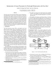
oundaries. Master cells are then <strong>fill</strong>ed in a Monte-Carlofashion, according to a priority scheme where master cellsthat are more severely under<strong>fill</strong>ed receive higher priority<strong>for</strong> <strong>fill</strong>ing at each iteration. This <strong>process</strong> continues untilall master cells are <strong>fill</strong>ed past the lower bound densitythreshold or the slack in all under<strong>fill</strong>ed master cells is exhausted.Monte-Carlo <strong>Hierarchical</strong> Fillin Alg orithmInput:Aierarchical-fixed-§ion,bufferdistance, w x w window, . upper _ _ bound U on<strong>for</strong> <strong>fill</strong>ing to the slack of a single master cell. We resolvewindow densitythe LLownershipl’ problem by fixing an order of all mas-Output:-HierarchiFlayout with <strong>fill</strong>ed master cells ter cells starting from the global master cell (containing1. For each Master Cell M; in the lavout Do2. Partition the Master Ckll Mq actordina to theviven rid size3. fior af rids in the Master Cell Do4. Mark fhe status of erid “OccuDied” if it iscovered by the orinrnal featurisor the sub Master-Cell5. For all instances Ij.of the Master Cell Mi Do6. If the instance Ij is overlapped with featuresor instances of other Master Cells Then7. Update the status of rids which are covered8. Calculate the Drioritv ofthe Master Cells9. While the sum of priority > 0 Do10. Use the Monte-Carlo method to select oneMaster Cell Mi11. Randomly select a slack grid position inthe master cell12. For each corresponding position of the gridin all instances of the Master Cell Mi Do13. If the insertion causes any window densityto exceed the upper bound U Then14. Discard the insertion15. Lock slack grid position16. Go over all other grids in master cell coveredbv the exceeded window and lock them17. Else18.19.20.Increase the <strong>fill</strong> area of the Master CellAdd the <strong>fill</strong> geometry into the Master CellUpdate the relevant windows’ densitiesFigure 2: Monte-Carlo <strong>Hierarchical</strong> Filling Algorithm.(2) The overlap between two instances of different mastercells.(3) The overlap between more than two instances of differentmaster cells.(4) The overlap between two or more than two instancesof the same master cell.For each region of master cell overlap we must determinewhich master cell “owns” that intersection region.In other words, it is necessary to assign the space availableentire layout) down to individual features. The hierarchycan be represented as the acyclic directed graph Hwith the set of nodes consisting of all master cells andindividual features. The graph H has an arc from themaster cell A to the master cell or the feature B if Bparticipates in the definition of A. The topological orderof the graph H is an order of its nodes in which the beginningof any arc is later than its end in respect to thisorder. The topological order of the graph H is obtainedby breadth-first-search traversing of H starting from theglobal master cell. The containment-based topological orderingof the hierarchy corresponds to the topological orderof the graph H. Then no master cell later in the ordermay use in its definition master cells appeared earlier inthe order. Every time when we have an intersection ofmaster cell instances, we check which of the master cellsappears later in the topological order and assign the intersectionarea to this master cell. This way we correctlyresolve the overlap cases (1-3). Un<strong>for</strong>tunately, the case(4) cannot be resolved in this manner because hierarchycannot distinguish different instances of the same mastercell. Thus, we exclude the overlapping regions from theslack of the master cell thus leaving the them unavailable<strong>for</strong> <strong>fill</strong>.A. Slack Computation <strong>for</strong> <strong>Hierarchical</strong> LayoutsFor each master cell, <strong>dummy</strong> <strong>fill</strong> may be inserted onlyinto the slack (i.e., free) area of a master cell, not into itssubcells. Computing the slack of a master cell proceeds byfirst determining the number of grid positions inside thebounding box of the master cell, while excluding all positionsthat overlap with either a “bloated” feature (Le., a<strong>for</strong>bidden buffer zone around each feature) or a “bloated”subcell. However, slack area computation is complicatedby the fact that instances of master cells may overlap.Such overlaps can occur between the master cell instanceand the features, or between two or more master cell instances(see Figure 3). In general, overlaps may have avery complicated structure. We distinguish the followingcases:(1) The overlap between a master cell instance and afeature.Figure 3: Computing master cell intersections: thedark features and patterned subcells may either completelyor partially overlap with a given master cell.B. A Hybrid <strong>Hierarchical</strong> / Flat Filling ApproachPure hierarchical <strong>fill</strong>ing may tend to result in somesparse or un<strong>fill</strong>ed regions (e.g., due to overlaps betweendifferent instances of master cells and features or due tothe interactions among the “bloat” regions around master142
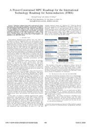
cells), which could yield an unacceptably high layout densityvariation. A natural and simple solution is to applya post-<strong>process</strong>ing “cleanup” phase, i.e., apply a standardflat <strong>fill</strong> algorithm to the output of the hierarchical phase.However, a purely flat <strong>fill</strong> approach, even when applied asa secondary post-<strong>process</strong>ing phase, may greatly increasethe resulting data volume and runtime, negating the benefitsof using a hierarchical approach in the first place.We propose a new algorithm <strong>for</strong> mitigating this drawback,by combining hierarchical <strong>fill</strong>ing techniques witha flat <strong>fill</strong>ing approach, in a way that smoothly tradesoff the respective efficiency and accuracy of these twoapproaches. In our proposed method, varying a usercontrolledparameter yields a smooth tradeoff among solutionquality, data volume, and runtime, as confirmedby our computational experience. Our three-phase hybridhierarchical-flat <strong>fill</strong>ing approach is summarized as follows:1. A purely hierarchical <strong>fill</strong> phase; followed by2. A split-hierarchical phase, where certain master cellsthat were deemed to be under<strong>fill</strong>ed in phase 1, wouldbe replicated so that distinct copies of the same mastercell may be <strong>fill</strong>ed differently than other copies ofthe same master cell; and finally,3. A flat <strong>fill</strong> “cleanup” phase (say, Monte-Carlo based),which will <strong>fill</strong> any remaining sparse or un<strong>fill</strong>ed regionsthat were not <strong>process</strong>ed satisfactorily during the firsttwo phases.The overall goal with this strategy is to quickly <strong>fill</strong> asmuch of the layout as possible in phases 1 and 2 whilekeeping the <strong>fill</strong> output data volume relatively low, andthen further improve and tune the resulting <strong>fill</strong>ed layoutusing a flat <strong>fill</strong>ing approach in phase 3 on the (presumablysmall number of) remaining sparse or un<strong>fill</strong>ed areas.In particular, phase 2 consists of repeatedly splittingmaster cells located in regions which were determined tobe under<strong>fill</strong>ed during phase 1, as follows. Given a topdowncontainment-based topological ordering of the nmaster cells, i.e. C1, C2, C3, . . . , Cn-2 , C,-l, C,, wherea master cell Ci can only contain master cell Cj iff i < j,a master cell Ci may be split into two master cells Ci,land Ci,2 and any Cj containing master cell Ci is thenmodified to point to either the copy Ci91 or Ci,2 (say,randomly chosen). More generally, rather than per<strong>for</strong>mingonly two-way splits, we can per<strong>for</strong>m k-way splits (seeFigure 4).Varying the parameter IC (which controls the split factor)from 1 (pure hierarchical) to infinity (pure flat),yields a smooth tradeoff between solution quality, datavolume, and runtime. As k is increased, the solution qualityasymptotically approaches that of flat <strong>fill</strong>. If the resultof hierarchical <strong>fill</strong>ing does not satisfy the technologicalconstraints, then we recommend <strong>for</strong>egoing the original hierarchyin favor of a more uni<strong>for</strong>m <strong>fill</strong>ing. This can beimplemented by storing in the original cell library different<strong>fill</strong>ed versions of each master. Such a scheme will notnecessarily slow down verification, since having fixed permanentstructure, they can be “pre-verified” , and thusdramatically improve the uni<strong>for</strong>mity of hierarchical <strong>fill</strong>ingwithout a large runtime increase.k-Way Master Cell Spl itting Alg orithmInput: Kerarchical layout, and a spIitting parameter kOutDut: New hierarchical layout with new copiesof master cellsFor i = 1 to n DoCreate k new copies of Ci, namely Ci,llCi,z, ... Ci,kFor an master cell C’ containing in the master cellc; I30For all 1 5 j 5 k Doput an arc from the master cell Ci,j to C’For any master cell C which contains master cell Ci DoReplace Ci inside C with copy Ci,j <strong>for</strong>random j, 15 j 5 kIn hierarchy H , replace the arc (C, Ci) with (C, Ci,j)Output resulting new hierarchical layoutFigure 4: Improving the hierarchical <strong>fill</strong>ing approach bysplitting master cells k-ways: each master cell is replacedwith k distinct masters, each of which may be <strong>fill</strong>ed independentlyand differently.Following the approach of [l], our implementation hasthe following capabilities: grid slack computation; doughnutarea computation; wraparound window density analysisand synthesis; and compressed <strong>fill</strong> insertion.IV. COMPUTATIONAL EXPERIENCEOur experimental testbed integrates GDSII Stream inputand internally-developed geometric <strong>process</strong>ing engines,coded in C++ under Solaris. Our experiments wereper<strong>for</strong>med using part of a metal layer extracted from hierarchicalGDSII from an industry custom-block layout.Table 1 lists the attributes of our three test cases, i.e.,layout size and number of rectangle^.^I Test Cases ITable 1: Parameters of test cases.Table 2 compares the minimum window density, datavolume (i.e., the number of <strong>fill</strong> geometry references in theresulting GDSII output file), and the number of <strong>dummy</strong><strong>fill</strong> features (i.e., the number of <strong>fill</strong> geometries on the resultinglayout after flattening) <strong>for</strong> five heuristics: (i) hierarchical,(ii) flat, (iii) 2-way splitting, (iv) hybrid ofhierarchical and flat, and (v) hybrid of the hierarchical,splitting and flat approaches. For each test case, we ran41n the given coordinate system, 40 units is equivalent to 1micron.143
~ ._..all the five <strong>fill</strong>ing heuristics on both the spatial densitymodel and the effective density model, with the windowdensity upper bound equal to the original maximum windowdensity.H+S+FFlatOrgLayoutHierH+FH+S. _..4374 I17500 I 0.421 I/ 7234 120829 I 0.38313974 1 13974 I 0.527 11 23415 I23415 1 0.443Testcaw ~ _ 3 -_0.000 0.0914995 22566 0.071 4449 20320 0.1577472 25043 0.532 9461 25332 0.3719690 23622 0.102 8575 22990 0.159H+S+F 11 12212 I26144 I 0.540 11 13285 I25700 1 0.394Flat 11 17695 117695 I 0.547 11 31204 I31204 I 0.483Table 2: The <strong>Hierarchical</strong>, Flat and Hybrid Filling Approaches.Notation: OrgLayout: original layout; SpatialDen: spatial density model; Effective Den: effective densitymodel; data: data volume, i.e., the number of <strong>fill</strong>geometry references in resulting GDSII output file; # <strong>fill</strong>:number of real <strong>dummy</strong> <strong>fill</strong> features on the resulting layout;MinDen: minimum window density of the layout;Hier: hierarchical <strong>fill</strong>ing approach; H+F: hierarchical +flat <strong>fill</strong>ing approach; H+S: hierarchical + 2-way mastercell splitting <strong>fill</strong>ing approach; H+SfF: hierarchical + 2-way master cell splitting + flat <strong>fill</strong>ing approach; Flat: flat<strong>fill</strong>ing approach.Table 2 indicates that the Flat Monte-Carlo approachobtains the best-quality result (i.e., highest minimum density)but results in the largest data volume. On the otherhand, the <strong>Hierarchical</strong> Monte-Carlo approach saves ondata volume but yields low-quality results. The hybridsof hierarchical and flat <strong>fill</strong> approaches produce substantiallyimproved results, with only a modest increase indata volume. Finally, we observe that the IC-way MasterCell Splitting approach smoothly trades off between per<strong>for</strong>manceand data volume, i.e., it provides better resultsthan the pure <strong>Hierarchical</strong> Fill approach and less datavolume than the pure Flat Filling approach.v. CONCLUSIONS AND FUTURE DIRECTIONSIn conclusion, we have addressed the hierarchical <strong>fill</strong>ingproblem in layout density control <strong>for</strong> CMP uni<strong>for</strong>mity. Wepresented a practical approach to hierarchical <strong>fill</strong> synthe-sis, which trades off runtime, solution quality, and outputdata volume. Distinct copies of a master cell are allowedto be <strong>fill</strong>ed differently, which improves the solution qualityin a user-controlled manner. Our system also generates<strong>fill</strong>ing geometries in compressed GDSII <strong>for</strong>mat, which reducesthe resulting <strong>fill</strong> data volume. Experiments indicatethat this new hybrid hierarchical <strong>fill</strong>ing approach isscalable, efficient, and highly competitive with previousMonte-Carlo and LP-based methods.Ongoing research includes developing alternate purehierarchical<strong>fill</strong>ing heuristics, and developing more robusthierarchy manipulators <strong>for</strong> in-memory layout representations,in order to enable smoother tradeoffs between solutionquality and data volume. We also seek to make our<strong>fill</strong> solutions reusable, so that <strong>fill</strong> solutions can be storedin a library along with the master cells, and would nothave to be recomputed from scratch in cases where a cellis used in a context that has different density constraints.However, the reusability methodology can be only appliedto master cells which are neither overlapped with othermaster cells, nor routed over. One way of achieving such“unrollable” solutions is to produce and store a <strong>fill</strong> solutionin a “monotone” manner, so that successively longerprefixes of a <strong>fill</strong> solution would still constitute valid <strong>fill</strong>solutions in lower density contexts.REFERENCES[l] Y. Chen, A. B. Kahng, G. Robins and A. Zelikovsky, “PracticalIterated Fill Synthesis <strong>for</strong> CMP Uni<strong>for</strong>mity”, Proc. <strong>Design</strong><strong>Automation</strong> Conf., June 2000, pp. 671-674.[2] Y. Chen, A. B. Kahng, G. Robins and A. Zelikovsky, “NewMonte-Carlo Algorithms <strong>for</strong> Layout Density Control”, Proc.ASP-DAC, 2000, pp. 523-528.[3] R. R. Divecha, B. E. Stine, D. 0. Ouma, J. U. Yoon, D. S.Boning, et al., “Effect of Fine-line Density and Pitch on InterconnectILD Thickness Variation in Oxide CMP Process”,Proc. CMP-MIC, 1998.[4] 3. G. Garofalo, J. Q. Zhao, J. Blatch<strong>for</strong>d and E. Nease, “Applicationsof enhanced optical proximity correction models”,Proc. SPIE Optical Microlithography XI, SPIE Vol. 3334, Feb.1998.[5] A. B. Kahng, G. Robins, A. Singh, H. Wang and A. Zelikovsky,“Filling Algorithms and Analyses <strong>for</strong> Layout Density Control”,IEEE Trans. Computer-Aided <strong>Design</strong> 18(4) (1999), pp. 445-462.[6] H. Landis, P. Burke, W. Cote, W. Hill, C. Hoffman, et al.,“Integration of Chemical-Mechanical Polishing into CMOS IntegratedCircuit Manufacturing”, Thin Solid Films 220(20)(1992), pp. 1-7.[7] W. Maly, “Moore’s Law and Physical <strong>Design</strong> of ICs”, (specialaddress), Proc. ISPD, 1998.[B] G. Nanz and L. E. Camilletti, “Modeling of Chemical MechanicalPolishing: A Review”, IEEE Trans. on SemiconductorManufacturing 8(4) (1995), pp. 382-389.[9] International Technology Roadmap <strong>for</strong> Semiconductors, Dec1999, www.itrs.net/l999-SIA_Roadmap/Home.htm[lo] J. Rey, personal communication, 2000.[ll] B. Stine, “A Closed-Form Analytical Model <strong>for</strong> ILD ThicknessVariation in CMP Processes”, Proc. CMP-MIC, 1997.[12] R. Tian, D. Wong, and R. Boone, “Model-Based Dummy FeaturePlacement <strong>for</strong> Oxide Chemical-Mechanical Polishing Manufacturability”Proc. <strong>Design</strong> <strong>Automation</strong> Conf., June 2000, pp.667-670.[13] M. Tomozawa, “Oxide CMP Mechanisms”, Solid State Technology40(7) (1997), pp. 169-175.144