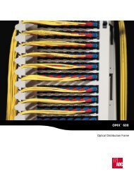
Wired Assemblies
Wired Assemblies
Wired Assemblies
- No tags were found...
Create successful ePaper yourself
Turn your PDF publications into a flip-book with our unique Google optimized e-Paper software.
AP ChemistryChapter 11. Intermolecular Forces, Liquids, and SolidsChapter 11. Intermolecular Forces, Liquids, and SolidsCommon Student Misconceptions• Students confuse intermolecular and intramolecular forces.• Students have difficulty in predicting the relative strength of intermolecular forces involved in differentmaterials.• Students confuse cohesion and adhesion.• Students do not realize that under the right set of conditions water also sublimes.• The term volatile is often used incorrectly, especially in the media.Lecture Outline11.1 A Molecular Comparison of Liquids and Solids• Intermolecular forces physical properties of liquids and solidsStates of MatterSolidShape Volume Density Compressible? MassLiquidGasSolid Liquid GasEnergy ---------------------------------------------------------------------------------------------• Solids and liquids are condensed phases.• Converting a gas into a liquid or solid requires the molecules to get closer to each other.• We can accomplish this by cooling or compressing the gas.• Converting a solid into a liquid or gas requires the molecules to move further apart.• We can accomplish this by heating or reducing the pressure on the gas.• The forces holding solids and liquids together are called intermolecular forces.- 1 -
Modular Patch PanelsFeatures and Benefits9/00 • 187 Termination/<strong>Wired</strong> Access Products• Provides connectivity to virtually any type ofequipment using unshielded twisted pair (UTP)• LAN workstations• Wiring hubs• Trunk lines• Printers• Fax machines• Concentrators• Servers• T1 lines• Voice circuits• Tested for reliable, digital operation of up to10 Mbps• Can be used effectively for 10 Mbps Ethernet,10BaseT, token ring at 4 Mbps, T1 or ISDNapplications• 50-pin connectors or wire-wrap terminalslocated on rear of panel for equipmenttermination• Installed in wiring closet in rack or on a wall(with optional bracket kit); or can be placed inan enclosed cabinet rack in end user work areaSpecifications are found on page 58.Pair 2Pair 3 Pair1 Pair 412345 678TIA 568 APair 3Pair 2 Pair1 Pair 412345678TIA 568 BMPP-N28BA1 (front)MPP-N28BA1 (rear)MPP-CXFBA1 (front)Pair 4Pair 3Pair 2Pair112345678USOCPair 1Pair 21234567810 Base T(4 Wire)MPP panels can be ordered in several wiring schemes. The TIA-568A and TIA 568B wiring schemes are those recommended by theTIA Commercial Building and Wiring Standards Committee.w w w . a d c . c o m • + 1 - 9 5 2 - 9 3 8 - 8 0 8 017
<strong>Wired</strong> <strong>Assemblies</strong>ApplicationsIn the central office, wired assembly jackfields, inserted into VF circuits between different officeequipment, provide jack access for testing and rerouting (patching) circuits.9/00 • 187 Termination/<strong>Wired</strong> Access ProductsRECEIVE SIDESGSBEMRECEIVEEMSGSBOPTIONAL SIGNALING LEADSFOR DIGITAL SWITCHEM TYPE II SIGNALING INTERFACESTELCO INTERFACEST1R1DEMEQINMODEM4-WIRERTMODEQOUTT1 R1 R T4-Wire Jackfield (no monitor)in a Customer Premises ApplicationCHANNEL BANKT1 R1 R TDEMEQINMONLINESIGEQRECEIVEMODEQOUTMONTRANSMIT4-WIRE ANALOG TRUNKTRANSMIT SIDETRANSMITDISTRIBUTION FRAME TERMINAL BLOCK4- and 6-Wire Jackfield in a Telco ApplicationTTELCO INTERFACESRLINEDROP/MONTRMODEMApplication BetweenModem and Cable Pairw w w . a d c . c o m • + 1 - 9 5 2 - 9 3 8 - 8 0 8 019
<strong>Wired</strong> <strong>Assemblies</strong>Bantam Connectorized Jackfields2-Wire JackfieldFeatures and Benefits9/00 • 187 Termination/<strong>Wired</strong> Access ProductsThe JC2 Bantam jackfield provides forty-eight orninety-six 2-wire circuits, including monitorjacks. Circuit connections are made throughstandard 50-pin connectors mounted on therear of the chassis. Line connectors are receptacles,drops are plugs.• Front panel hinged for internal access• Horizontal designation strips furnished witha white card and clear window for circuitidentification• Vertical designation cards printed with rowfunctions4-Wire JackfieldFeatures and BenefitsThe JC4 Bantam jackfield provides seventeen ortwenty-four 4-wire circuits,including monitorjacks. Circuit connections are made throughstandard 50-pin connectors on the rear of thechassis. Equipment IN and MOD are receptacles;Equipment OUT and DEMOD are plugs.• Front panel hinged for internal access• Horizontal designation strips furnished witha white card and clear window for circuitidentification• Vertical designation cards printed with rowfunctions6-Wire JackfieldFeatures and BenefitsThe JC6 Bantam jackfield provides twelve, twentyfour or forty-eight 6-wire circuits, consisting ofDEM/MOD, EQ IN/ EQ OUT, MOD and Signaljacks. Circuit connections are made throughstandard 50-pin connectors on the rear of thechassis. Equipment IN and MOD are receptacles;Equipment OUT and DEMOD are plugs.• Front panel hinged for internal access• Horizontal designation strips furnished witha white card and clear window for circuitidentification• Vertical designation cards printed with rowfunctionsRTT1R1JC2/48R1T1T1R1R1T1T1R1R1T1T1R1MEEMLINEDROPRTT1R1DEMEQINMONDEMEQINJC4/24JC2/48LDMJC4/48MDEMEQINMONLINESIGEQMODEQOUTMONMODEQOUTMODEQOUTMONLINEDROP/MONRTTRRTTRRTTRJC2/48MRTTRLINEDROPMONJC6/48Mw w w . a d c . c o m • + 1 - 9 5 2 - 9 3 8 - 8 0 8 020
<strong>Wired</strong> <strong>Assemblies</strong>Specialty JackfieldsQCP Jackfields9/00 • 187 Termination/<strong>Wired</strong> Access ProductsThe QCP jackfield provides a means of accessing 2- and 4-wire circuits at a point that is nonconnectorizedand in which stranded VF cable has been used. The QCP contacts on the rear of the jackfield utilizeADC’s split cylinder, punch down insulation displacement contact. The split cylinder contacts accept 22,24 and 26 AWG solid or stranded wire. These contacts provide the capability of quickly rewiring the jackfieldfor new circuits, or changing the circuits from 2-wire to 4-wire or from 4-wire back to 2-wire circuits.A special insertion tool is required for connecting the cable to the panel.Ordering InformationDescriptionQCP Jackfield2-Wire or 4-Wire Line Drop/MonitorAccessoriesImpact tool with tipSpare tipManual toolTool holderDimensions (H x W x D)3.5" x 19" x 8"(8.90 x 48.26 x 20.32 cm)For wired assemblies accessories such as patch cords, mounting hardware and plugs, see pages 38-52.# of Circuits24 or 48Catalog NumberJQ2/48M - JQ4/24MQ915QB-2TQ115Q150w w w . a d c . c o m • + 1 - 9 5 2 - 9 3 8 - 8 0 8 023
<strong>Wired</strong> <strong>Assemblies</strong>Bantam Prewired Jackfields2-Wire Jackfield9/00 • 187 Termination/<strong>Wired</strong> Access ProductsFeatures and BenefitsThe JB2 Bantam jackfields provide forty-eightor ninety-six 2-wire circuits, including monitorjacks. Circuit connections are made by wiringthe equipment to easy-access wire-wrap terminalblocks on the back of the jackfield.• Front panel hinged for internal access• Horizontal designation strips furnishedwith a white card and clear window forcircuit identification• Vertical designation cards printed withrow functions4-Wire JackfieldFeatures and BenefitsThe JB4 Bantam jackfield provides twenty-four4-wire circuits, including monitor jacks. Circuitconnections are made by wiring the equipmentto easy-access wire-wrap terminal blocks onthe back of the jackfield.• Front panel hinged for internal access• Horizontal designation strips furnishedwith a white card and clear window focircuit identification• Vertical designation cards printed with rowfunctions6-Wire JackfieldFeatures and BenefitsThe JB6 Bantam jackfield provides twelve orforty-eight 6-wire circuits, consisting ofDEM/MOD, EQ IN/ EQ OUT, MON and Signaljacks. Circuit connections are made by wiringthe equipment to easy-access wire-wrap terminalblocks on the back of the jackfield.• Front panel hinged for internal access• Horizontal designation strips furnishedwith a white card and clear window forcircuit identificationRTT1R1JB2/48R1T1T1R1R1T1T1R1LINEDROPDEMEQINMONRTTRJB4/24MDEMEQINMONJB2/48MMODEQOUTMONMODEQOUTMONLINEDROPMONRTTRRTTR• Vertical designation cards printed with rowfunctionsMEEMLINESIGEQJB6/48Mw w w . a d c . c o m • + 1 - 9 5 2 - 9 3 8 - 8 0 8 025
<strong>Wired</strong> <strong>Assemblies</strong>Voice Frequency Jackfields9/00 • 187 Termination/<strong>Wired</strong> Access ProductsADC VF jackfields support the network manager who needs to access, monitor, test and patch VF circuits.VF jackfields allow monitoring and testing of VF circuits, on either side of the line (telco or modem,transmit or receive), without circuit interruption. Circuit paths for both 2-wire and 4-wire lines can bechanged with a single action. Built to exceed Bell System and MIL-J-641 Standards, ADC VF or Bantamjackfields have been tested to 50,000 operations. ADC VF jackfields save space, are easily installed andaid in VF line organization. Special plugs to split, open and terminate lines are available.Modem JackfieldFeatures and BenefitsADC’s modem jackfield provides complete accessand patch facilities for twenty-four 4-wire orforty-eight 2-wire lines. LINE and MODEM jackson the front allow patching of any line to anymodem access for test equipment. Front panelMONITOR jack access provides a bridgingconnection across the line. All jacks are prewiredto 50-pin connectors located at the rear of thepanel. The jacks accept 3 conductor Bantamplugs (2 conductors plus braided shield).• Horizontal designation strips furnished witha white card and clear window for circuitidentification• Row functions are permanently marked forease of operation• Plexiglass dust cover provided• FCC registered (Part 68)In-Line JackfieldFeatures and BenefitsThe in-line jackfield provides patching facilitiesfor sixteen 4-wire lines or thirty-two 2-wirelines. Front panel LINE, MODEM and MONITORjacks are aligned to correspond with ADC’sPatchMate digital patching or ADC’sPatchMate with switch product lines. Whenused with those products, the placement of thein-line jackfield directly above or beneath itsrespective digital port aids in the identificationof affected lines to speed trouble shooting. LINEand MODEM jack access allows patching of anyline to any modem or access for test equipment.The MONITOR jack access provides a bridgingconnection across the line. All jacks areprewired to 50-pin connectors located at therear of the panel.• FCC registered (Part 68)TO AUX 1TERMINALSTRIPCOMMONSLEEVE TOTERMINALSTRIPRTRTTRRTTRTRANSMITTRANSMITLINEMODMONLINEMODMONDMMOJ-1LINEMODMONR1T1AUX 1LINEMODMONPMAJ-1AUX 2RECEIVERECEIVERTTRRTTRSchematic typical of 16 4-wire transmit andreceive circuits or 2 circuits shown for 2-wireRTR1T1TO AUX 2TERMINALSTRIPw w w . a d c . c o m • + 1 - 9 5 2 - 9 3 8 - 8 0 8 027
<strong>Wired</strong> <strong>Assemblies</strong>Telephone Line Isolation PanelThe Telephone Line Isolation Panel provides asafe and easy means of accessing phone linesfor testing at power substations.9/00 • 187 Termination/<strong>Wired</strong> Access ProductsThe PI-250 panel and associated plugs are speciallydesigned to provide protection up to20,000 volts between the line side and theequipment side as well as between the adjacentcircuits within the panel. The panels are availablein several versions. The three types of availableplugs, Looping Plugs, Shorting Plugs andReverse Polarity Plugs, have color-coded handlesfor easy identification.The panel is usually located at or near thedemarcation between the telephone company’sin-plant or building wiring, usually at the pointof entrance into the building. The panel allowsline access for repair personnel while protectingthem from high voltages on the lines duringelectrical storms and power failures.One side of the panel is the telephone companyside where telephone cables enter thepower substations. The other side is the powercompany equipment side. To open the phonecircuits for testing in either direction, you simplyremove the plugs from the panel, opening thephone company lines from the power companyequipment. Lines can be accessed in both directionsthrough telephone type jacks, recessedwithin the molded panel in such a way as tomake accidental contact with the jacksextremely difficult.The isolation panel is completely enclosed in atransparent safety shield, making it virtuallyimpossible for test personnel to come in contactwith the active circuits. The speciallydesigned ADC plugs are rated at 20,000 volts,well over the necessary protection level.ADC’s Telephone Line Isolation Panel also providesa less time-consuming, less costly andmore efficient means of access. No moreunwrapping circuits or breaking solder connections.All you do is remove a plug and your circuitsare automatically disconnected for testing.TOISOLATINGDEVICETOISOLATINGDEVICETOISOLATINGDEVICETelephone IsolationPanel Jack SchematicRTPJ40Looping PlugRTRTPJ41Shorting PlugRTRTRTPJ42Reverse Polarity PlugTOCENTRALOFFICETOCENTRALOFFICETOCENTRALOFFICEw w w . a d c . c o m • + 1 - 9 5 2 - 9 3 8 - 8 0 8 029
<strong>Wired</strong> <strong>Assemblies</strong>Telephone Line Isolation PanelOrdering InformationDescriptionDimensions (H x W x D)Catalog Number9/00 • 187 Termination/<strong>Wired</strong> Access ProductsPanels with Wire-Wrap Terminations5 linesPanels with Screw Terminals4 lines5 lines10 linesPlugsLooping plug (white)Shorting plug (black)Reverse polarity plug (red)6.0" x 6.45" x 4.5"(15.24 x 16.38 x 11.43 cm)6.0" x 5.21" x 4.5"(15.24 x 13.23 x 11.43 cm)6.0" x 6.45" x 4.5"(15.24 x 16.38 x 11.43 cm)6.0" x 12.7" x 4.5"(15.24 x 32.26 x 11.43 cm)PI-250-1PI-250-8PI-250-7PI-250-9PJ40PJ41PJ42Height shown is the height of the panels with plug. Without the plugs, the height of panels with wire-wrap terminations is 5.19"(13.18 cm); the height of the panels with screw terminals is 5.4" (13.72 cm).w w w . a d c . c o m • + 1 - 9 5 2 - 9 3 8 - 8 0 8 030
<strong>Wired</strong> <strong>Assemblies</strong>Timing Jackfields9/00 • 187 Termination/<strong>Wired</strong> Access ProductsTiming jackfields provide 20 circuits for terminationof a timing source generator. These panelsprovide patching and monitoring capabilitiesfor T1 clock output. The panels’ outputs areindividually cabled to any piece of equipmentrequiring a T1 clock.Ordering InformationDescriptionTiming JackfieldsBantam timing jackfield;2-wire digital jackfield;includes monitor jacksLongframe timing jackfield; 2-wire digital jackfield;includes monitor jacksDimensions (H x W x D)3.5" x 19.0" x 8.0"(8.89 x 48.26 x 20.32 cm)4.0" x 19.0" x 8.0"(10.16 x 48.26 x 20.32 cm)For wired assemblies accessories such as patch cords, mounting hardware and plugs, see pages 38-52.# of Circuits2020Catalog NumberAUX-3A0001AUX-3A0002w w w . a d c . c o m • + 1 - 9 5 2 - 9 3 8 - 8 0 8 031
<strong>Wired</strong> <strong>Assemblies</strong>Longframe Connectorized Jackfields2-Wire Jackfield9/00 • 187 Termination/<strong>Wired</strong> Access ProductsFeatures and BenefitsThe JLC2/24 Longframe (310) jackfield providestwenty-four 2-wire circuits. Circuit connectionsare made through standard 50-pin connectorsmounted on the rear of the chassis. Line connectorsare receptacles, drops are plugs.• Rear panel hinged for internal access• Horizontal designation strips furnishedwith a white card and clear window forcircuit identification• Vertical designation cards printed with rowfunctions4-Wire JackfieldFeatures and BenefitsThe JLC4/12M jackfield provides twelve 4-wirecircuits, including monitor jacks. Circuit connectionsare made through standard 50-pinconnectors on the rear of the chassis.Equipment IN and MOD are receptacles;Equipment OUT and DEMOD are plugs.• Rear panel hinged for internal access• Horizontal designation strips furnishedwith a white card and clear window forcircuit identification• Vertical designation cards printed with rowfunctionsOrdering InformationDescription2-WireLine, drop circuits can beisolated for independentmonitoring; jacks acceptLongframe (310) threeconductorplugsDrop circuits can be isolated forindependent monitoring;monitor jacks accept 310type plugs4-WireMonitor jacks accept 309 typeplugsDimensions (H x W x D)1.75" x 19.0" x 8.0"(4.45 x 48.26 x 20.32 cm)2.63" x 19.0" x 8.0"(6.68 x 48.26 x 20.32 cm)2.63" x 19.0" x 8.0"(6.68 x 48.26 x 20.32 cm)R1T1T1R1RTT1R1JLC2/24# of Circuits242412DEMEQINMONJLC4/12MLINEDROPMODEQOUTMONCatalog NumberJLC2/24JLC2/24-310MJLC4/12MRTTRFor wired assemblies accessories such as patch cords, mounting hardware and plugs, see pages 38-52.w w w . a d c . c o m • + 1 - 9 5 2 - 9 3 8 - 8 0 8 032
<strong>Wired</strong> <strong>Assemblies</strong>Longframe Prewired Jackfields2-Wire Jackfield9/00 • 187 Termination/<strong>Wired</strong> Access ProductsFeatures and BenefitsThe J2 Longframe (310) jackfields providetwenty-four 2-wire circuits, including monitorjacks. Circuit connections are made by wiringthe equipment to easy-access wire-wrap terminalsblocks on the back of the jackfield.• Rear panel hinged for internal access• Horizontal designation strips furnishedwith a white card and clear window forcircuit identification• Vertical designation cards printed with rowfunctionsOrdering InformationDescription2-WireWith Line, Drop and Monitor;monitor jacks accept 310type plugsDimensions (H x W x D)2.63" x 19.0" x 8.0"(6.68 x 48.26 x 20.32 cm)For wired assemblies accessories such as patch cords, mounting hardware and plugs, see pages 38-52.# of Circuits24Catalog NumberJL2/24-310Mw w w . a d c . c o m • + 1 - 9 5 2 - 9 3 8 - 8 0 8 033
<strong>Wired</strong> <strong>Assemblies</strong>AccessoriesReplacement Designation Strip Cards and Windows9/00 • 187 Termination/<strong>Wired</strong> Access ProductsOrdering InformationHinge Side Hinge Side Lock Side Lock Side Horizontal HorizontalVertical Vertical Vertical Vertical (Above Jacks) (Above Jacks)Card Window Card Window Card WindowTYPE FIG DVHC- DVHW- DVLC- DVLW- DHC- HDW-01 1 -1200 -0010 -1740 -0010 -0020 -0010 (.44" wide)02 2 -1440 -0010 -1400 -0010 -0020 -0010 (.44" wide)03 3 -2020 -0010 -2390 -0010 -0040 -0040 (.225" wide)04 4 -2030 -0030 -2400 -0020 -0020 -001005 5 -2140 -0010 -2680 -0010 -0020 -001006 6 -1130 -0010 -2380 -0010 -0040 -004008 8 -0040 -0040thru thru -1370 -0040 -2190 -003009 9 -0020 -0010For Type and Figure references, please see pages 59-66.w w w . a d c . c o m • + 1 - 9 5 2 - 9 3 8 - 8 0 8 034
Modular Patch PanelSpecifications9/00 • 187 Termination/<strong>Wired</strong> Access ProductsMATERIALS:Split Cylinder & Split Cylinder:Wire-wrap Tail:Tin plated high strength phosphor bronzeInsulator:Flame retardant thermoplastic, oxygen index ≥ 28, UL94-VOPanels:Aluminum, powder painted white, 19" or 23" (48.26 or 58.42 cm)Connectors:50-, 64-, 36- and 24-pin connectors, male or femaleChassis and Cover:Steel, powder paintedPanels:Aluminum, powder painted white, 19" or 23" (48.26 or 58.42 cm)Chassis and Cover:Steel, powder paintedDust Covers:Attached to each connector before shipmentCable Locking or Tying Feature: Provided for each connectorELECTRICALCrosstalk: Speed Frequency Isolation2 Mbps 1 MHz
<strong>Wired</strong> <strong>Assemblies</strong>Figure 1Type 01 Jackfield (JC2/48)9/00 • 187 Termination/<strong>Wired</strong> Access ProductsRear View (Rotated)Top ViewFront ViewLINEDROPRTT1R11.75" MAX(44.45 mm)PJ889WSCHEMATIC,TYPICAL OF 48 CIRCUITS(4) 4-40 THREADS THRULINE 25-48 J2 P1 DROP 1-24LINE 1-2450 1 DROP 25-48J1P350 25 261 25 26JACK CIRCUIT #1 JACK CIRCUIT #48LINEDROP18.31"(46.50 cm)19"(48.26 cm)TO PLUG CONNECTOR PINT1 26CKT. 1 DROPR1 1CKT. 24CKT. 25CKT. 48REPEATEDDROPDROPREPEATEDDROPT149R1 24T1 26R1 1T1 49R1 24CONNECTION TABLEP1P28" ± .12"(20.32 ± .3 cm)(4) .25" x .44" SLOTS(6.35 x 11.18 mm)1.25"(31.75 mm)TO REC. CONNECTOR PINT 26CKT. 1 LINER 1CKT. 24CKT. 25CKT. 48REPEATEDLINELINEREPEATEDLINEPOSITION OF CARDAND WINDOWT49R 24T 26R 1T 49R 24J1J2LINEDROPw w w . a d c . c o m • + 1 - 9 5 2 - 9 3 8 - 8 0 8 059
<strong>Wired</strong> <strong>Assemblies</strong>Figure 2Type 02 Jackfield (JC2/48LDM)Rear View (Rotated)(4) 4-40 THREADS THRU9/00 • 187 Termination/<strong>Wired</strong> Access ProductsTop ViewFront ViewLINEDROP/MONRTT1R11.75" MAX(44.45 mm)PJ889WSCHEMATIC,TYPICAL OF 48 CIRCUITSLINE 25-48 J2 P1 DROP 1-24LINE 1-2450 1 DROP 25-48J1P350 25 261 25 26JACK CIRCUIT #1 JACK CIRCUIT #48LINEDROP/MON18.31"(46.50 cm)19"(48.37 cm)TO PLUG CONNECTOR PINT1 26CKT. 1 DROPR1 1CKT. 24CKT. 25CKT. 48REPEATEDDROPDROPREPEATEDDROPT149R1 24T1 26R1 1T1 49R1 24CONNECTION TABLEP1P28" ± .12"(20.32 ± .3 cm)POSITION OF CARDAND WINDOW1.25"(31.75 mm)TO REC. CONNECTOR PINT 26CKT. 1 LINER 1CKT. 24CKT. 25CKT. 48REPEATEDLINELINEREPEATEDLINE(4) .25" x .44" SLOTS(6.35 x 11.18 mm)T49R 24T 26R 1T 49R 24J1J2LINEDROP/MONw w w . a d c . c o m • + 1 - 9 5 2 - 9 3 8 - 8 0 8 060
<strong>Wired</strong> <strong>Assemblies</strong>Figure 3Type 03 Jackfield (JC2/48M)Rear View (Rotated)(4) 4-40 THREADS THRU9/00 • 187 Termination/<strong>Wired</strong> Access ProductsTop ViewFront ViewLINEDROPMONRTTR1.75" MAX(44.45 mm)PJ831WSCHEMATIC,TYPICAL OF 48 CIRCUITSLINE 25-48 J2 P1 DROP 1-24LINE 1-2450 1 DROP 25-48J125 P350 261 25 26JACK CIRCUIT #1 JACK CIRCUIT #48LINEDROPMON18.31"(46.50 cm)19"(48.26 cm)TO PLUG CONNECTOR PINT 26CKT. 1 DROPR 1CKT. 24CKT. 25CKT. 48REPEATEDDROPDROPREPEATEDDROPT49R 24T 26R 1T 49R 24CONNECTION TABLEP1P21.25"(31.75 mm)TO REC. CONNECTOR PINT 26CKT. 1 LINER 1CKT. 24CKT. 25CKT. 48REPEATEDLINELINEREPEATEDLINE8" ± .12"(20.32 ± .3 cm)POSITION OF CARDAND WINDOW(4) .25" x .44" SLOTS(6.35 x 11.18 mm)T49R 24T 26R 1T 49R 24J1J2LINEDROPMONw w w . a d c . c o m • + 1 - 9 5 2 - 9 3 8 - 8 0 8 061
<strong>Wired</strong> <strong>Assemblies</strong>Figure 4Type 04 Jackfield (JC2/96)Rear View (Rotated)(4) 4-40 THREADS THRU9/00 • 187 Termination/<strong>Wired</strong> Access ProductsTop ViewFront ViewLINEDROPLINEDROPRTT1R13.50" MAX(88.9 mm)PJ889WSCHEMATIC,TYPICAL OF 96 CIRCUITSLINE 49-72 J3 P1 DROP 1-24LINE 1-2450 1J1 25 2650 25LINE 73-96LINE 25-4850J22550 25J4 P21 26DROP 25-481 26DROP 73-96P41 26JACK CIRCUIT #4918.31"(46.50 cm)19"(48.26 cm)JACK CIRCUIT #96TO PLUG CONNECTOR PINT1 26CKT. 1 DROPR1 1CKT. 24CKT. 25CKT. 48REPEATEDDROPDROPREPEATEDDROPREPEATEDT149R1 24T1 26R1 1P3T1 49R1 24DROP 49-72JACK CIRCUIT #1 JACK CIRCUIT #48LINEDROPCKT. 49CKT. 72CKT. 73CKT. 96DROPREPEATEDDROPDROPDROPT1 26R1 1T149R1 24T1 26R1 1T1 49R1 24CONNECTION TABLEP1P2P3P4TO REC. CONNECTOR PINT 26CKT. 1 LINER 1CKT. 24CKT. 25CKT. 48CKT. 49CKT. 72CKT. 73CKT. 968" ± .12"(20.32 ± .3 cm)REPEATEDLINELINEREPEATEDLINELINEREPEATEDLINELINEREPEATEDLINEPOSITION OF CARDAND WINDOW(4) .25" x .44" SLOTS(6.35 x 11.18 mm)LINEDROP.50" (12.7 mm)LINE1.25" (2) DROP(31.75 mm)T49R 24T 26R 1T 49R 24T 26R 1T49R 24T 26R 1T 49R 24J1J2J3J4w w w . a d c . c o m • + 1 - 9 5 2 - 9 3 8 - 8 0 8 062
<strong>Wired</strong> <strong>Assemblies</strong>Figure 5Type 05 Jackfield (JC4/24)Rear View (Rotated)(4) 4-40 THREADS THRU9/00 • 187 Termination/<strong>Wired</strong> Access ProductsR1T1T1R1Top ViewFront ViewDEMODEQ INPJ889W1.75" MAX(44.45 mm)DEMEQINMODEQOUTSCHEMATIC,TYPICAL OF 24 CIRCUITSEQ IN 1-24 J2 P1 DEM 1-24MOD 1-2450 1J1 25 26 P350 2518.31"(46.50 cm)19"(48.26 cm)TO PLUG CONNECTOR PINT1 26CKT. 1 DEMR1 1CKT. 24CKT. 1CKT. 24REPEATEDDEMEQ OUTREPEATEDEQ OUTEQ OUT 1-241 26JACK CIRCUIT #1 JACK CIRCUIT #24PJ889WRTTRT149R1 24T 26R 1T 49R 248" ± .12"(20.32 ± .3 cm)CONNECTION TABLEP1P2POSITION OF CARDAND WINDOW(4) .25" x .44" SLOTS(6.35 x 11.18 mm)1.25"(31.75 mm)TO REC. CONNECTOR PINT 26CKT. 1 MODR 1REPEATEDMODEQ OUTT 49CKT. 24 MODR 24T1 26CKT. 1 EQ INR1 1REPEATEDT1 49CKT. 24 EQ INR1 24J1J2w w w . a d c . c o m • + 1 - 9 5 2 - 9 3 8 - 8 0 8 063
<strong>Wired</strong> <strong>Assemblies</strong>Figure 6Type 06 Jackfield (JC4/24M)Rear View (Rotated)(4) 4-40 THREADS THRU9/00 • 187 Termination/<strong>Wired</strong> Access ProductsR1T1T1R1Top ViewFront ViewDEMODEQ INMONPJ831W1.75" MAX(44.45 mm)DEMEQINMONMODEQOUTMONSCHEMATIC,TYPICAL OF 24 CIRCUITSEQ IN 1-24 J2 P1 DEM 1-24MOD 1-2450 1J1 25 26 P350 2518.31"(46.50 cm)19"(48.26 cm)TO PLUG CONNECTOR PINT1 26CKT. 1 DEMR1 1CKT. 24CKT. 1CKT. 24REPEATEDDEMEQ OUTREPEATEDEQ OUTEQ OUT 1-241 26JACK CIRCUIT #1 JACK CIRCUIT #24PJ831WRTTRT149R1 24T 26R 1T 49R 248" ± .12"(20.32 ± .3 cm)CONNECTION TABLEP1P2POSITION OF CARDAND WINDOW(4) .25" x .44" SLOTS(6.35 x 11.18 mm)1.25"(31.75 mm)TO REC. CONNECTOR PINT 26CKT. 1 MODR 1REPEATEDMODEQ OUTMONT 49CKT. 24 MODR 24T1 26CKT. 1 EQ INR1 1REPEATEDT1 49CKT. 24 EQ INR1 24J1J2w w w . a d c . c o m • + 1 - 9 5 2 - 9 3 8 - 8 0 8 064
<strong>Wired</strong> <strong>Assemblies</strong>Figure 8Type 08 Jackfield (JC6/48M)Rear Rear View View (Rotated)(12) 4-40 THREADS THRU9/00 • 187 Termination/<strong>Wired</strong> Access ProductsR1T1T1R1MEEMTop ViewFront ViewDEMODEQ INMONLINESIGEQMONDEMEQ INPJ831WPJ889W5.25" MAX(13.35 cm)DEMEQINMONLINESIGEQMODEQOUTMONSCHEMATIC,TYPICAL OF 48 CIRCUITSEQ IN 1-24 J4 P1 DEM 1-24MOD 1-2450 1J1 25 26 P450 25EQ OUT 1-241 26150 25150 251 26EQ IN 25-48DEM 25-48J5 P2MOD 25-48EQ OUT 25-4850 25J2 26 P51 26SIG LINE 25-48SIG EQ 1-24J6 P3SIG LINE 1-24SIG EQ 25-4850 25J3 26 P68" ± .12"(20.32 ± .3 cm)POSITION OF CARDAND WINDOW(4) .25" x .44" SLOTSJACK CIRCUIT #1 JACK CIRCUIT #24(6.35 x 11.18 mm)1.25"MOD(31.75 mm) EQ OUTMON.50" (12.7 mm)LINESIGEQMONMODEQ OUTJACK CIRCUIT #2518.31"JACK CIRCUIT #48(46.50 cm)19"(48.26 cm)PJ831WRTTRCONNECTION TABLETO PLUG CONNECTOR PINTO REC. CONNECTOR PINT1 26T 26CKT. 1 DEMCKT. 1 MODR1 1R 1REPEATEDP1REPEATEDT1 49T 49CKT. 24 DEMCKT. 24 MODR1 24R 24T1 26T 26CKT. 25 DEMCKT. 25 MODR1 1R 1REPEATEDP2REPEATEDT1 49T 49CKT. 48 DEMCKT. 48 MODR1 24R 24T 26T1 26CKT. 1 EQ OUTCKT. 1 EQ INR 1R1 1REPEATEDP4REPEATEDT 49T1 49CKT. 24 EQ OUTCKT. 24 EQ INR 24R1 24T 26T1 26CKT. 25 EQ OUTCKT. 25 EQ INR 1R1 1REPEATEDP5REPEATEDT 49T1 49CKT. 48 EQ OUTCKT. 48 EQ INR 24R1 24E 26E 26CKT. 1 SIG EQCKT. 1 SIG LINEM 1M 1REPEATEDP3REPEATEDE 49E 49CKT. 24 SIG EQCKT. 24 SIG LINEM 24M 24E 26E 26CKT. 25 SIG EQCKT. 25 SIG LINEM 1M 1REPEATEDP6REPEATEDE 49E 49CKT. 48 SIG EQCKT. 48 SIG LINEM 24M 24J1J2J4J5J3J6w w w . a d c . c o m • + 1 - 9 5 2 - 9 3 8 - 8 0 8 065
<strong>Wired</strong> <strong>Assemblies</strong>Figure 9Type 09 Jackfield (JC6/48SC)9/00 • 187 Termination/<strong>Wired</strong> Access ProductsR1T1T1R1MEEMRear Rear View View (Rotated)Top ViewFront ViewDEMODEQ INMONLINESIGEQMONDEMEQ IN5.25" MAX(13.34 cm)PJ831WPJ889WDEMEQINMONLINESIGEQMODEQOUTMONSCHEMATIC,TYPICAL OF 48 CIRCUITS(12) 4-40 THREADS THRUEQ IN 1-24 J4 P1 DEM 1-24MOD 1-2450 1J1 25 26 P450 25EQ IN 25-48 J5 P2 DEM 25-48MOD 25-4850 1J2 25 26 P550 25M SIG LINE 1-48 J6 P3 M SIG EQ 1-48E SIG LINE 1-4850 1J3 25 26 P650 25JACK CIRCUIT #1JACK CIRCUIT #25PJ831W18.31"(46.50 cm)19"(48.26 cm)RTTREQ OUT 1-241 26EQ OUT 25-481 26E SIG EQ 1-481 268" ± .12"(20.32 ± .3 cm)POSITION OF CARDAND WINDOW(12) .25" x .44" SLOTSJACK CIRCUIT #24(6.35 x 11.18 mm)1.25"MOD(31.75 mm) EQ OUTMON.50" (12.7 mm)LINESIGEQJACK CIRCUIT #48MONMODEQ OUTCONNECTION TABLETO PLUG CONNECTOR PINTO REC. CONNECTOR PINT1 26T 26CKT. 1 DEMCKT. 1 MODR1 1R 1REPEATEDP1REPEATEDT1 49T 49CKT. 24 DEMCKT. 24 MODR1 24R 24T1 26T 26CKT. 25 DEMCKT. 25 MODR1 1R 1REPEATEDP2REPEATEDT1 49T 49CKT. 48 DEMCKT. 48 MODR1 24R 24T 26T1 26CKT. 1 EQ OUTCKT. 1 EQ INR 1R1 1REPEATEDP4REPEATEDT 49T1 49CKT. 24 EQ OUTCKT. 24 EQ INR 24R1 24T 26T1 26CKT. 25 EQ OUTCKT. 25 EQ INR 1R1 1REPEATEDP5REPEATEDT 49T1 49CKT. 48 EQ OUTCKT. 48 EQ INR 24R1 24CKT. 1E 1CKT. 1E 1SIG EQSIG LINECKT. 2E 2CKT. 2E 2REPEATEDP6REPEATEDCKT. 47E 48CKT. 47E 48SIG EQSIG LINECKT. 48E 49CKT. 48E 49CKT. 1M 1CKT. 1M 1SIG EQSIG LINECKT. 2M 2CKT. 2M 2REPEATEDP3REPEATEDCKT. 47M 48CKT. 47M 48SIG EQSIG LINECKT. 48M 49CKT. 48M 49J1J2J4J5J3J6w w w . a d c . c o m • + 1 - 9 5 2 - 9 3 8 - 8 0 8 066
Web Site: www.adc.comFrom North America, Call Toll Free: 1-800-366-3891 • Outside of North America: +1-952-938-8080 Fax: +1-952-946-3292For a complete listing of ADC's global sales office locations, please refer to our web site.ADC Telecommunications, Inc., P.O. Box 1101, Minneapolis, Minnesota USA 55440-1101Specifications published here are current as of the date of publication of this document. Because we are continuously improving ourproducts, ADC reserves the right to change specifications without prior notice. At any time, you may verify product specifications bycontacting our headquarters office in Minneapolis. ADC Telecommunications, Inc. views its patent portfolio as an important corporateasset and vigorously enforces its patents. Products or features contained herein may be covered by one or more U.S. or foreign patents.187 9/00 Revision ©1997,2000 ADC Telecommunications, Inc. All Rights Reserved An Equal Opportunity Employer2


