SL/SLX-6RS User Manual - Sixnet
SL/SLX-6RS User Manual - Sixnet
SL/SLX-6RS User Manual - Sixnet

You also want an ePaper? Increase the reach of your titles
YUMPU automatically turns print PDFs into web optimized ePapers that Google loves.
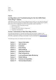
Slim Line(<strong>SL</strong>/<strong>SL</strong>X Series)USER MANUALIndustrial EthernetReal-Time-RingSwitchContents at a Glance:Section 1 General Information Page 4Section 2 LED Indicators Page 6Section 3 Installation Page 9Section 4 Power Wiring Page 13Section 5 Ethernet Wiring Page 14Section 6 Ring Switch Features Page 16Section 7 Ring Configurations Page 19Section 8 Local and Remote Status Monitoring Page 21Section 9 Default Settings Page 25Section 10 Features and Capabilities Page 26Section 11 Technical Specifications Page 28Section 12 Service Information Page 30This manual applies to the following products:• <strong>SL</strong>-<strong>6RS</strong> Series – 6 port models with 10/100 ports (Lexan case)• <strong>SL</strong>X-<strong>6RS</strong> Series – 6 port models with 10/100 ports (Aluminum case)<strong>6RS</strong> Ring Switch <strong>User</strong> <strong>Manual</strong> Page 1 of 30 Last Revised: 28-Aug-09<strong>Sixnet</strong> • 331 Ushers Road • Ballston Lake, NY 12019 • USA • 1.518.877.5173 • support@sixnet.com
<strong>Sixnet</strong> Protected Technology Policy:<strong>Sixnet</strong> protects your investment in <strong>Sixnet</strong> systems with long-term planned technology and our uniqueProtected Technology Policy. We will continue to support the specified capabilities of standard <strong>Sixnet</strong>products for at least five years. We plan each product improvement and new feature to be upward compatiblewith existing designs and installations. Our goals are to make each new software release bring new power toyour <strong>Sixnet</strong> systems and have every existing feature, applications program and data file continue to work.We protect your investment even further with a liberal five-year trade-in policy. Exchange standard productsfor upgraded versions of the same product to take advantage of new features and performance improvementsat any time for five years. A prorated trade-in allowance will be given for your existing equipment. <strong>Sixnet</strong>protects your long-term productivity with state-of-the-art planned technology and continued support.<strong>Sixnet</strong> Statement of Limited Warranty:<strong>Sixnet</strong> LLC, manufacturer of <strong>Sixnet</strong> products, warrants to Buyer that products, except software, manufactured by<strong>Sixnet</strong> will be free from defects in material and workmanship. <strong>Sixnet</strong>'s obligation under this warranty will be limited torepairing or replacing, at <strong>Sixnet</strong>'s option, the defective parts within one year of the date of installation, or within 18months of the date of shipment from the point of manufacture, whichever is sooner. Products may be returned byBuyer only after permission has been obtained from <strong>Sixnet</strong>. Buyer will prepay all freight charges to return anyproducts to the repair facility designated by <strong>Sixnet</strong>. This limited warranty does not cover losses or damages whichoccur in shipment to or from Buyer or due to improper installation, maintenance, misuse, neglect or any cause otherthan ordinary commercial or industrial applications. In particular, <strong>Sixnet</strong> makes no warranties whatsoever with respectto implied warranties of merchantability or fitness for any particular purpose. All such warranties are hereby expresslydisclaimed. No oral or written information or advice given by <strong>Sixnet</strong> or <strong>Sixnet</strong>’s representative shall create a warrantyor in any way increase the scope of this warranty. This limited warranty is in lieu of all other warranties whether oralor written, expressed or implied. <strong>Sixnet</strong>'s liability shall not exceed the price of the individual units, which are the basisof the claim. In no event shall <strong>Sixnet</strong> be liable for any loss of profits, loss of use of facilities or equipment, or otherindirect, incidental or consequential damages.INSTALLATION AND HAZARDOUS AREA WARNINGS:These products should not be used to replace proper safety interlocking. No software-based device (or any other solidstatedevice) should ever be designed to be responsible for the maintenance of consequential equipment or personnelsafety. In particular, <strong>Sixnet</strong> disclaims any responsibility for damages, either direct or consequential, that result from theuse of this equipment in any application.All power, input and output (I/O) wiring must be in accordance with Class I, Division 2 wiring methods and inaccordance with the authority having jurisdiction.WARNING(EXPLOSION HAZARD) -WARNING(EXPLOSION HAZARD) -WARNING(EXPLOSION HAZARD) -SUBSTITUTION OF COMPONENTS MAY IMPAIR SUITABILITY FORCLASS 1, DIVISION 2.WHEN IN HAZARDOUS LOCATIONS, DISCONNECT POWER BEFOREREPLACING OR WIRING UNITS.DO NOT DISCONNECT EQUIPMENT UNLESS POWER HAS BEENSWITCHED OFF OR THE AREA IS KNOWN TO BE NONHAZARDOUS.<strong>6RS</strong> Ring Switch <strong>User</strong> <strong>Manual</strong> Page 2 of 30 Last Revised: 28-Aug-09<strong>Sixnet</strong> • 331 Ushers Road • Ballston Lake, NY 12019 • USA • 1.518.877.5173 • support@sixnet.com
FCC Statement:This equipment has been tested and found to comply with the limits for a Class B digital device, pursuant to Part 15 ofthe FCC Rules. These limits are designed to provide reasonable protection against harmful interference in a residentialinstallation. This equipment generates uses and can radiate radio frequency energy and, if not installed and used inaccordance with the instructions, may cause harmful interference to radio communications. However, there is noguarantee that interference will not occur in a particular installation. If this equipment does cause harmful interferenceto radio or television reception, which can be determined by turning the equipment off and on, the user is encouragedto try to correct the interference by one or more of the following measures: Reorient or relocate the receiving antenna;Increase the separation between the equipment and receiver; Connect the equipment into an outlet on a circuit differentfrom that to which the receiver is connected; Consult the dealer or an experienced radio/TV technician for help.Copyright & Trademarks:Copyright © <strong>Sixnet</strong>, All Rights Reserved. Real-Time-Ring is a trademark of <strong>Sixnet</strong>.Note: All information in this document is subject to change without notice.<strong>6RS</strong> Ring Switch <strong>User</strong> <strong>Manual</strong> Page 3 of 30 Last Revised: 28-Aug-09<strong>Sixnet</strong> • 331 Ushers Road • Ballston Lake, NY 12019 • USA • 1.518.877.5173 • support@sixnet.com
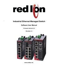
Section 1OverviewGeneral InformationThis manual will help you install and maintain the Real-Time-Ring TM Switch. The RingSwitch allows you to implement the traditional star topology, or ring topology to takeadvantage of network path redundancy. The switch can be used right out of the boxwithout configuration; or through some simple configuration steps, some powerfulmanaged switch features can be enabled such as traffic prioritization and port mirroring.OperationIn the Ring Switch, messages are intelligently routed for the sake of increasing theefficiency and reliability of your network. Unlike an Ethernet hub, a switch will forwardpackets to specific ports to reduce unnecessarytraffic on network paths, thus optimizingnetwork efficiency. Most importantly, by using aRing Switch, you can implement redundant pathsin a network by allowing ring topology (for amore resilient network). Ring topology isimportant in path redundancy because no matterwhere in the ring that a path gets “cut”, alldevices connected to a node in the ring will stillbe able to communicate with each other.Conventional switches and hubs cannot be usedin ring topologies because of broadcast storms.Broadcast storms can bring a network to a stop ifconventional switches or hubs are being used in aring topology because of broadcast messagereproduction. Using Ring Switches in the loopwill prevent broadcast storms because they havethe intelligence to detect loops and to assign thenecessary ports to be in the backup (disabled)state. These backup ports will be instantly enabled should the primary path in theirrespective ring fail. See picture to the right:The Ring Switch supports 10BaseT (10 Mbps) and 100BaseT (100 Mbps) on its RJ45ports. Each of these ports will independently auto-sense the speed, allowing you tointerface to regular or fast Ethernet devices. Some models also have 100BaseF (100 Mbps)optic ports.Refer to Section 6 for more information on Ring Switch configuration, operation andfeatures.<strong>6RS</strong> Ring Switch <strong>User</strong> <strong>Manual</strong> Page 4 of 30 Last Revised: 28-Aug-09<strong>Sixnet</strong> • 331 Ushers Road • Ballston Lake, NY 12019 • USA • 1.518.877.5173 • support@sixnet.com
PerformanceSpecificationsThese general specifications apply to the Real-Time-Ring TM Switch. Refer to Section 11for complete technical specifications.Ports 6Port types (varies by model)10/100BaseT (Shielded RJ45),100BaseF (SC or ST connectors)Ethernet switch typeIntelligent Store and Forward with Real-Time-Ring plus some management capabilitiesEthernet protocols supported All IEEE 802.3RJ45 operationFiber operationAuto negotiation, Auto-Crossover and Auto-PolarityMultimode or singlemode with distances up to 120km or moreStandardsand SafetyThe Ring Switch meets the following standards:Electrical safety - UL 508, CSA C22/14; EN61010-1EMC performance - FCC part 15, ICES 003; EN61000-6-2/4, CEPENDINGPENDINGHazardous locations – UL 1604, CSA C22.2/213 (Class 1, Div. 2), Groups A, B, C, D.<strong>SL</strong> enclosure : Cenelec EN50021 (Zone 2) EEx nA II T4 X (-40°C ≤ T a ≤ +60°C).<strong>SL</strong>X enclosure : Cenelec EN50021 (Zone 2) EEx nA II T4 X (-40°C ≤ T a ≤ +85°C).Install the Real-Time-Ring Switch in accordance with local and nationalelectrical codes.Lightning Danger: Do not work on equipment during periods of lightningactivity.Do not connect a telephone line into one of the Ethernet RJ45 connectors.<strong>6RS</strong> Ring Switch <strong>User</strong> <strong>Manual</strong> Page 5 of 30 Last Revised: 28-Aug-09<strong>Sixnet</strong> • 331 Ushers Road • Ballston Lake, NY 12019 • USA • 1.518.877.5173 • support@sixnet.com
Section 2OverviewLED IndicatorsThe Ring Switch has communication LEDs for each port and power LEDs for each inputterminal. In addition, two LEDS (OK and Ring) provide switch and network status. Refer tothe pictures below for the location of these LEDs.Power LEDsThere are two power LEDs on the switch. Both indicate if there is power applied to therespective terminal.<strong>6RS</strong> Ring Switch <strong>User</strong> <strong>Manual</strong> Page 6 of 30 Last Revised: 28-Aug-09<strong>Sixnet</strong> • 331 Ushers Road • Ballston Lake, NY 12019 • USA • 1.518.877.5173 • support@sixnet.com
OK LEDThe OK LED is a multifunctional indicator, which has several states defined below.Note: The OK LED and OK Output do not always coincide. In general the OK LEDwill always indicate any type of error condition. However the OK Output can beconfigured using the Ethernet Switch Tools to only indicate the errors you define.ON solid:The OK LED will be in a steady ON state when both P1 and P2 power inputs are poweredand that all configured rings have continuous ring integrity.OFF completely:The OK LED will be OFF if either P1 and/or P2 is not powered, or if any one of the activerings for which this switch is a member of encounters a segment failure.Blinking:The OK LED can blink at different rates.• Continuous rapid blinking: To verify communication and target switch selection,you can request the switch to “wink” its OK LED to visually identify the unit.• Rapid blinking, with a single short pause: Should the OK LED blink rapidly forabout 5 sec and then pause for about 1 second, this indicates that the switch is in theboot-up process such as on power-up, when loading firmware or when resetting theswitch.• Long OFF, short ON: If the OK LED is OFF for about 1.9 seconds and ON for .1seconds, an internal error has occurred in the unit. Try cycling power or resettingthe switch from the configuration utility.Ring LEDThe Ring LED is a multifunctional indicator that shows four states.ON solid:The Ring LED will be ON when all rings enabled in the switch have continuous ringintegrity.OFF completely:The switch has not been configured for any rings.Blinking: (50% OFF – 50% ON)One or more rings have been configured for the switch, but a break has been discovered forone or more of the configured rings. Neighboring Ring Switches are responding, so thebreak is at another location.Blip: (Long OFF – Short ON)One or more configured rings have been broken. The break has been detected to be local toone of the ports. Diagnostically speaking; in simple rings, the segment with the problemwill be between the two switches with their ring LEDs in the blip state. Also, you canascertain the general location of where the segment error has occurred with a HMI, a mastercontroller, or some other MODBUS Master through MODBUS/UDP polling. Find out moredetails about MODBUS diagnostics in section 8 of this manual.<strong>6RS</strong> Ring Switch <strong>User</strong> <strong>Manual</strong> Page 7 of 30 Last Revised: 28-Aug-09<strong>Sixnet</strong> • 331 Ushers Road • Ballston Lake, NY 12019 • USA • 1.518.877.5173 • support@sixnet.com
ACT / LNK/10/100 MbpsLEDsPorts 1-4:Activity, link, and port speed indication is combined into one LED per port. The port statesare described below:- ON solid: This would indicate that there is a proper Ethernet connection (Link)between the port and another Ethernet device, but no communications activity isdetected. The LED color indicates the speed see below.- OFF completely: This would indicate that there is not a proper Ethernet connection(Link) between the port and another Ethernet device. Make sure the proper cabletype is in use and that it has been plugged securely into the ports at both ends. Seesection 5 for proper Ethernet cabling.- Blinking: This would indicate that there is a proper Ethernet connection (Link)between the port and another Ethernet device, and that there is communicationsactivity. The LED color indicates the speed see below.- Green: 100 Mbps (100BaseT) connection is detected.- Yellow: 10 Mbps (10BaseT) connection is detected.Ports 5-6:The RJ45 connector version (all copper) use Two LED per port to indicate Activity, link,and port speed. The port states are described below:- LED OFF completely: This would indicate that there is not a proper Ethernetconnection (Link) between the port and another Ethernet device. Make sure theproper cable type is in use and that it has been plugged securely into the ports atboth ends. See section 5 for proper Ethernet cabling.- Yellow ON solid: This would indicate that there is a proper 10Mbps Ethernetconnection (Link) between the port and another Ethernet device, but nocommunications activity is detected.- Yellow ON Blinking: This would indicate that there is a proper 10Mbps Ethernetconnection (Link) between the port and another Ethernet device, and that there iscommunications activity.- Green ON solid: This would indicate that there is a proper 100Mbps Ethernetconnection (Link) between the port and another Ethernet device, but nocommunications activity is detected.- Green ON Blinking: This would indicate that there is a proper 100Mbps Ethernetconnection (Link) between the port and another Ethernet device, and that there iscommunications activity.<strong>6RS</strong> Ring Switch <strong>User</strong> <strong>Manual</strong> Page 8 of 30 Last Revised: 28-Aug-09<strong>Sixnet</strong> • 331 Ushers Road • Ballston Lake, NY 12019 • USA • 1.518.877.5173 • support@sixnet.com
Section 3OverviewInstallationThe Ring Switch can be mounted onto a standard DIN rail (EN50022) or screwed directlyto a flat panel. Refer to the mechanical drawings below. Make sure to allow enough roomto route your Ethernet cables.<strong>SL</strong> model in Lexan case:1Mounting2Recommended DIN rail mounting steps:1. Hook the top back of the unit over the DIN rail.2. Push the bottom of the unit towards the DIN rail until it snaps into place.RemovalBARecommended DIN rail removal steps:A. Insert screwdriver into DIN clip and pry until the bottom of the unit releases from the din rail.B. Unhook the top of the unit and remove it from the DIN rail.<strong>6RS</strong> Ring Switch <strong>User</strong> <strong>Manual</strong> Page 9 of 30 Last Revised: 28-Aug-09<strong>Sixnet</strong> • 331 Ushers Road • Ballston Lake, NY 12019 • USA • 1.518.877.5173 • support@sixnet.com
<strong>SL</strong>X model in metal case:1Mounting2Recommended DIN rail mounting steps:1. Hook the top back of the DIN rail clip on the unit over the din rail.2. Push the bottom of the unit towards the DIN rail until it snaps into place.ACRemovalBRecommended DIN rail removal steps:A. Push the whole unit down to free the bottom of the DIN rail clip. See blue circle area.B. Pull the bottom of the unit away from the DIN rail.C. Unhook the top of unit and remove it from the DIN rail.<strong>6RS</strong> Ring Switch <strong>User</strong> <strong>Manual</strong> Page 10 of 30 Last Revised: 28-Aug-09<strong>Sixnet</strong> • 331 Ushers Road • Ballston Lake, NY 12019 • USA • 1.518.877.5173 • support@sixnet.com
Removable Screw Block0.40" (1.02 cm)Typical forSC or ST fiber2.90"[7.35 cm]Snaps to standardDIN rail EN50022(35 mm)2/3/5Ports6/8/9Ports1.01"[2.57 cm]1.98"[5.02 cm]3.95"[10.03 cm]4.20"[10.67 cm]Dia. 0.15"(0.38 cm)Use for directpanel mountingto a flat surface1.98"[5.02 cm]1.01"[2.57 cm]1.00"[2.54 cm]1.50"[3.81 cm]3.26"[8.28 cm]0.06"[0.15 cm]1.38" [3.5 cm]DIN EN50022(not included withnot shown to scale;for reference only)1.06" [2.7 cm]0.30"[0.76 cm]Figure 3a – <strong>SL</strong> Enclosure Mechanical Dimensions<strong>6RS</strong> Ring Switch <strong>User</strong> <strong>Manual</strong> Page 11 of 30 Last Revised: 28-Aug-09<strong>Sixnet</strong> • 331 Ushers Road • Ballston Lake, NY 12019 • USA • 1.518.877.5173 • support@sixnet.com
<strong>SL</strong>XRemovable Screw Block0.175"[0.44 cm]0.40" (1.02 cm) Snaps to standardTypical for0.30" DIN rail EN50022SC or ST fiber[0.76 cm](35 mm)4.50"[11.43 cm]2/3/5Ports4.00"[10.16 cm]6/8/9Ports4.35"[11.05 cm]Use for direct panelmounting to a flatsurface with up to#8 screw for olderunits or up to #12for newer units(see guide to right)Removablefor direct panelmountingC2.25"[5.71 cm]2.25"[5.71 cm]Panel mounting ears onnewer models acceptup to a #12 screw1.10"[2.79 cm]0.55"[1.40 cm]1.60"[4.06 cm]0.80"[2.03 cm]1.50"[3.81 cm]3.00"[7.62 cm]Direct to panelmounting guide0.39"[0.99 cm]1.38" [3.5 cm]DIN EN50022(not included withnot shown to scale;for reference only)1.06" [2.7 cm]0.30"[0.76 cm]Figure 3b – <strong>SL</strong>X Enclosure Mechanical Dimensions<strong>6RS</strong> Ring Switch <strong>User</strong> <strong>Manual</strong> Page 12 of 30 Last Revised: 28-Aug-09<strong>Sixnet</strong> • 331 Ushers Road • Ballston Lake, NY 12019 • USA • 1.518.877.5173 • support@sixnet.com
Section 4OverviewPower WiringThese Ring switches can be powered from the same DC source that is used to power yourother devices. A voltage in the range of 10 to 30 VDC needs to be applied between the P1(plus) terminal and the Minus terminal as shown in the diagrams. To reduce down timeresulting from power loss, these industrial Ethernet switches can optionally be poweredredundantly with a second power supply as shown in the diagrams.The managed models also have an “OK” output that can be tied to a PLC input or otherdevice to indicate when there is a power loss. When ON, this output will source the samevoltage that is applied to the switches power terminals. See the wiring diagrams.WIRINGWARNINGSBEFORE PERFORMING ANY WIRING TO THESE SWITCHES MAKE SURE …• THE AREA IS CURRENTLY NONHAZARDOUS (ESPECIALLY WHENWORKING IN CLASS I, DIV 2 OR ZONE 2 HAZARDOUS LOCATIONS)• TO TURN OFF THE POWER TO THE SWITCH• TO UNPLUG THE SCREW TERMINAL BLOCK (This is especially important onthe units that have a metal case as shown below. Connecting or disconnectingwires to the screw block when it is in place and the power is turned on canallow the screwdriver to short the power to the case.)Screw TorqueWhen tightening the screws be careful to tighten to a max. torque of 5 in/lb (0.57 Nm).Wiring DiagramFront ofSwitch(connectors)Single DC SupplyP2P1AlarmOutputLoad+ +--OK(opt.)Chassis GND ismade through theDIN rail mountingDual DC SuppliesOKAlarmOutputLoad(opt.)Back ofSwitch(DIN rail)Single DC Power Redundant DC PowerFigure 4a – Power & Alarm Wiring DiagramP2P1<strong>6RS</strong> Ring Switch <strong>User</strong> <strong>Manual</strong> Page 13 of 30 Last Revised: 28-Aug-09<strong>Sixnet</strong> • 331 Ushers Road • Ballston Lake, NY 12019 • USA • 1.518.877.5173 • support@sixnet.com
Section 5OverviewRJ45 WiringGuidelinesEthernet CablePin-outs(for referenceonly)EthernetConnectorPin PositionsEthernet WiringThe Ring Switch provides Ethernet and fiber connections to devices on the factory floorthrough star or ring topology. When wiring the Ring Switch in a ring topology, it isimportant that only Ring Switches are used for each node in the ring. With proper ringwiring, all nodes in the ring can maintain the same data connectivity should a path in thering be “cut”. Be sure to visit Section 7 for detailed examples about valid and invalid ringtopologies.Use data-quality (not voice-quality) twisted pair cable rated category 5 or better withstandard RJ45 connectors. For best performance use shielded cable. Straight through orcrossover category 5 cable can be used regardless of the type of device connected to theRing Switch. This is because the Ring Switch supports auto-mdi/mdix-crossover.Straight-thru Cable WiringCross-over Cable WiringPin 1 Pin 1 Pin 1 Pin 3Pin 2 Pin 2 Pin 2 Pin 6Pin 3 Pin 3 Pin 3 Pin 1Pin 6 Pin 6 Pin 6 Pin 2Cable DistanceThe maximum cablelength for 10/100/1000BaseT is typically 100meters (328 ft.).EthernetFiber WiringGuidelinesThe Ring Switch optionally has one or two pair of multimode or singlemode fiber ports.The maximum segment length is up to 120+ km depending on the type of fiber optictransceiver installed in the switch. Refer to the technical specifications for details.Each fiber optic port on the switch is comprised of a pair of SC or ST style connectors. Foreach fiber port there is a transmit (TX) and receive (RX) signal. When making your fiberoptic connections, make sure that the transmit (TX) port of the switch connects to thereceive (RX) port of the other device, and the receive (RX) port of the switch connects tothe transmit (TX) port of the other device. See the image below for the location of the fiberports.The ACT/LNK LED will be ON solid when you have made a proper connection.<strong>6RS</strong> Ring Switch <strong>User</strong> <strong>Manual</strong> Page 14 of 30 Last Revised: 28-Aug-09<strong>Sixnet</strong> • 331 Ushers Road • Ballston Lake, NY 12019 • USA • 1.518.877.5173 • support@sixnet.com
DuplexOperationNetworkDevice CheckThe RJ45 ports will auto-sense for Full or Half duplex operation, while the fiber ports areconfigured for full duplex operation. Note: Fiber devices with half duplex settings shouldstill communicate with the switch. If otherwise then contact your switch vendor.The Ring Switch is capable of supporting 10/100BaseT and 100BaseF. Make sure youconnect the appropriate devices to each port.<strong>6RS</strong> Ring Switch <strong>User</strong> <strong>Manual</strong> Page 15 of 30 Last Revised: 28-Aug-09<strong>Sixnet</strong> • 331 Ushers Road • Ballston Lake, NY 12019 • USA • 1.518.877.5173 • support@sixnet.com
Section 6OverviewRing Switch FeaturesThe Ring Switch has all the networking capability of a typical unmanaged switch plus someadvanced capability that you would only find in a managed switch. Like an unmanagedswitch, the Ring Switch is “plug and play” meaning that it can be used right out of the box -without any user configuration. This includes the ring functionality, which is already preconfiguredin the switch. For most applications this is all that is needed. For advancedapplications you can use the Ethernet Switch Tools (Windows software utility) to enablesome advanced capabilities such as priority queuing for prioritizing your traffic, messagerate filtering for broadcast storm protection and port mirroring for diagnostics.Important Note: Only use Real-Time-Ring Switches when connecting switches in aring. The Real-Time-Ring Switches use a specialized high-speed ring algorithm that onlythey will understand. Otherwise, these Ring Switches are fully IEEE 802.3 compatible.Ring Setup &OperationFor ring operation in most applications, no user configuration is necessary. The RingSwitches can be ordered pre-configured with 1 or more pairs of ports setup for ringoperation. Just connect the ring-configured ports of your Ring Switches in a ring byconnecting the last switch back to the first. Make sure you use only the ring configuredports for your ring connections. The non-ring ports should be used to connect to yourEthernet devices such as PLCs, computers, etc. Be sure to visit Section 7 for great examplesabout valid and invalid ring topologies.<strong>6RS</strong> Ring Switch <strong>User</strong> <strong>Manual</strong> Page 16 of 30 Last Revised: 28-Aug-09<strong>Sixnet</strong> • 331 Ushers Road • Ballston Lake, NY 12019 • USA • 1.518.877.5173 • support@sixnet.com
Ring AlgorithmandPerformanceThe Real-Time-Ring feature utilizes a special algorithm that assures very fast recoverytimes. Each Real-Time-Ring switch utilizes the special high-speed algorithm to keep trackof the health of the ring. In a healthy ring (a complete ring), one ring switch will beautomatically picked to act as a master (switch with lowest MAC address) for the ringnetwork. Alternatively, you can designate one of your ring switches to be the master usingthe Ethernet Switch Tools. It is the master switch’s job to determine which one of its localring ports are to be in the forwarding or backup state. The ring port chosen to be in thebackup state is where the backup segment of the ring will be. By default, the ring port withthe higher port number will become the backup port.All ring switches in the ring must have a way to keep track of each other in case a failure incommunication occurs along the ring. To keep track of the health of the ring, the Ringswitches periodically send test messages to each other. Therefore, when a ring gets “cut” ata certain location, the Ring switches will know and they will take the appropriate action tobring the network back online. The time that it takes for the last Ring switch to “know” andtake appropriate action to rectify the communication problem will be when the link loss“recovers”.Recovery time can be estimated by multiplying 5 mS times the number of switches, andthen adding 30 mS (for loss of link errors) or 60 mS (for message loss errors). For example,a ring of 10 switches would have a recovery time of 80 mS for the typical loss of link typeerrors.Master SwitchSelectionEthernetSwitch ToolsAs mentioned above, the ring switch with the lowest MAC address will automaticallybecome the master and block one of its ports (highest number port). Alternatively, you candesignate one of your ring switches to be the master using the Ethernet Switch Tools. Thereis a simple check box where you can select “Automatic” or “This Switch” for the masterring switch selection. This advanced capability allows you to control where the backup portwill be in your network. It is recommended that only one ring switch be designated as themaster. If more than one is designated as the master then the one with the lowest MACaddress will prevail.In some applications it may be desirable or required to adjust the Ring Switches parametersfor proper or best operation. A Microsoft Windows software utility called the EthernetSwitch Tools is provided to make these adjustments. By using the “auto-find” feature in theutility, you will be able to pick from a list of detected Ring Switches and load customconfigurations via Ethernet. The auto-find feature eliminates the hassle of loading via aserial connection and the overhead time spent assigning IP addresses. Refer to the onlinehelp for details on using the Ethernet Switch Tools.IMPORTANT NOTE: Your computer must be on the same local network as the RingSwitch for the Ethernet Switch Tools to operate properly. Also, your computer must haveupdated Raw Ethernet Socket (WinPcap) support installed. When installing the EthernetSwitch Tools, the installation program will call the WinPcap installation program ifnecessary. If you have an older version of WinPcap installed, the installation programwill prompt you to remove the older version before continuing with the installation.PortConfigurationRing Switches auto-negotiate port settings. In most applications port settings are best left inthe default "Auto" connection mode. For special situations, the ports can be "Fixed" torestrict communications to only 10 or 100 Megabits per second, with either half or fullduplex. Flow control can be enabled or disabled as well. Port configuration settings areadjustable using the Ethernet Switch Tools.<strong>6RS</strong> Ring Switch <strong>User</strong> <strong>Manual</strong> Page 17 of 30 Last Revised: 28-Aug-09<strong>Sixnet</strong> • 331 Ushers Road • Ballston Lake, NY 12019 • USA • 1.518.877.5173 • support@sixnet.com
Fault TolerantRingsA network backbone wired in a ring type topology is one of the best choices for a faulttolerantnetwork. By default, Ring Switches may be factory preset to have zero, one, or tworings enabled. Factory presetting a ring configuration skips the step of using the EthernetSwitch Tools to enable your rings so you can have the convenience of “plug and play”operation. Factory presets are indicated in the switch’s part number:-D0 Rings disabled-D1 One ring enabled on last two ports (default)-D2 Two rings enabled on ports 1 and 2 and last two ports-DC A user specified custom configuration has been pre-installedTo change the ring configuration in the switch, simply launch the Ethernet Switch Toolsand choose the desired pair of ports for your new enabled ring. The Ring LED will be lit ifall rings (one or two) that are enabled in this switch have continuous ring integrity.For a ring to function, all switches in the path of the ring must have Real-Time-Ringsupport. Do not connect rings within rings. Only simple non-overlapped rings are allowed.Two active rings cannot share a network segment. It is possible to join two rings togetherby configuring two rings in a single switch. The ports used for each ring must be distinct,so that no network segment is shared by both rings. See Section 7 for ring wiring examplesand guidelines.Message RateFiltering(Broadcast stormprotection)Priority Queuing(Traffic Prioritizationusing QoS, CoS,ToS/DiffServ)Port MirroringPoorly configured applications and devices or malicious users can flood your network withbroadcast packets that are forwarded to all ports and can quickly consume most of anetwork’s bandwidth. The Ring Switch provides protection against broadcast storms bylimiting the quantity of broadcast and multicast messages. This protection is enabled bydefault. See Ethernet Switch Tool’s on-line help for details.With priority queuing configured in the Ring Switch, low priority data will not interferewith your time critical data again. Network traffic can be prioritized to achieve theperformance that time-sensitive data demands. Refer to the Ethernet Switch Tool’s on-linehelp for more information and details on configuring priority queuing.This advanced diagnostic capability allows messages from one or more ports to be copiedto another port. Then a port analyzer or “sniffer” program can be used to monitor the trafficwithout affecting the operation of the switch. Configuring the Ring Switch for portmirroring is done through the Ethernet Switch Tools. See the on-line help for details.<strong>6RS</strong> Ring Switch <strong>User</strong> <strong>Manual</strong> Page 18 of 30 Last Revised: 28-Aug-09<strong>Sixnet</strong> • 331 Ushers Road • Ballston Lake, NY 12019 • USA • 1.518.877.5173 • support@sixnet.com
Section 7ConfiguringRings in yourRing SwitchRing ConfigurationsFirst and foremost, make sure that ring operation is enabled for the appropriate ports. Inother words it is required to tell the Ring Switch what ports it is going to use as ring ports(unless the Ring Switch was purchased with rings pre-configured). Never wire a RingSwitch in a ring topology without having the ports that are used in the ring configured asring ports (See diagram below).Valid RingTopologiesBelow are examples of how you should wire your Ring Switches together. In general, youshould keep your topology simple.<strong>6RS</strong> Ring Switch <strong>User</strong> <strong>Manual</strong> Page 19 of 30 Last Revised: 28-Aug-09<strong>Sixnet</strong> • 331 Ushers Road • Ballston Lake, NY 12019 • USA • 1.518.877.5173 • support@sixnet.com
Invalid RingTopologiesThe examples below are invalid ring topologies. Do NOT connect Ring Switches in theways shown below, as they will lead to unpredictable network performance. Paths indicatedby the color red create unintended rings (see unintended rings example below).UnintendedRings ExampleRefer to the diagram below. In this example, Ring Switches A and B have been softwareconfigured for two rings each. Ring Switches C and D have been software configured forone ring each. The physical connections for the two rings are shown in blue and red.Since the rule for configuring Ring Switches is to make sure that each Ring Switch knowsabout all rings that are attached to it, it would appear that the example below is legal.However, this is not the case. There are actually more than two ring paths that were created.There are multiple paths that traffic can use to move from Switch A and back to Switch A.The same applies to Switch B. These unintended Ring paths that Switch A and Switch Bdon’t know about are labeled as Unintended Rings A, B, C, and D.Since Ring Switch A and Ring Switch B don’t know about these extra ring paths, theyaren’t included in A or B’s ring algorithm. Paths that are not included in the ring algorithmwill result in harmful broadcast storms, as will happen when conventional switches areconnected in a ring topology.CABD<strong>6RS</strong> Ring Switch <strong>User</strong> <strong>Manual</strong> Page 20 of 30 Last Revised: 28-Aug-09<strong>Sixnet</strong> • 331 Ushers Road • Ballston Lake, NY 12019 • USA • 1.518.877.5173 • support@sixnet.com
Section 8SwitchStatusLocal and Remote Status MonitoringYou can keep track of the status of your Ring Switches at all times. To check the status of aRing Switch visually, you can monitor the Ring Switch’s indicator LEDs. To monitor thestatus remotely, you can use Modbus over Ethernet (UDP). There is also an alarm outputthat can be tied to a PLC or other supervisory device.Visual StatusMonitoringPort Status(ACT/LNK LED)Power & SwitchStatus (OK LED)Ring Status(Ring LED)The status of your Ring Switches can be easily ascertained by simply looking at their LEDindicators. The LEDs can be used to quickly see the status or to locate a network problem.See Section 2 for details on the LED indicators.After all Ethernet and/or fiber connections are made, check the LED’s corresponding to theports that each of the devices are connected to. Ensure that for each port that is in use, theLED is on or blinking. If a port LED is off, go back and check for connectivity problemsbetween that port and the network device connected to that particular port. In addition, thecolor of the LED should indicate the speed for which your device is connected at (yellow –10Mbps, green – 100Mpbs).The Ring Switch has an OK LED that indicates the power and operational status. It is ONsolid when there are no errors. It will go OFF if either power supply fails or a ring break isdetected. The OK LED will also flash if the switch is being “winked”, is in the boot-upmode, or an internal error was detected.The Ring Switch has a Ring LED that indicates the status of your ring connections. It is ONsolid when all rings handled by the switch have continuous integrity. It will be blinking ifthere is broken ring segment but all adjacent switches are responding. It will be OFF if theswitch is not configured for any rings. The ring LED will Blip (mostly OFF, with a quickON) when a configured ring has been broken and the break is local to one of the ports of theswitch. Typically the network with the fault will be between the two switches with RingLEDs in the Blip state. This makes tracking down faults quick and simple.<strong>6RS</strong> Ring Switch <strong>User</strong> <strong>Manual</strong> Page 21 of 30 Last Revised: 28-Aug-09<strong>Sixnet</strong> Technology Park • 331 Ushers Road • Ballston Lake, NY 12019 • USA • +1-518-877-5173 • support@sixnet.com
OK OutputRemoteStatusMonitoringThe Ring Switch has an OK Output that can be used to signal an error to a PLC, PC or othersupervisory devices. By default, this output is normally ON when both power inputs arepresent and there are no ring errors. The output will go OFF if either power input fails, bothpower inputs fail or there is a ring break detected. Alternatively, using the Ethernet SwitchTools you can define which error conditions will cause the OK Output to go OFF.There are two ways to remotely monitor the status of your Ring Switch network.The first method is to use the Ethernet Switch Tool’s status display. This display will showthe status of the selected Ring Switch by providing details such as port, power, and ringstates. Find more details about how to use this display by referring to the Ethernet SwitchTool’s on-line help.The second method that can be used for determining the state of your Ring Switch networkis via Modbus UDP. See the Modbus UDP topic below for detailed information about howto take advantage of this feature.Modbus/ UDPThrough Modbus over Ethernet (UDP or TCP), you can remotely monitor the status of theRing Switch. Using the Ethernet Switch Tools, the Ring Switch can be configured as aModbus slave station with its own Modbus station number and IP address.The Ring Switch has a set of predefined Modbus registers for status reporting. Refer to thetable below for the register assignments.ModbusAddressStatusModbusAddress10001 Link on port 1 10019StatusRing 1: Second port ispassing data (not blocked)10002 Link on port 2 10020 Ring 2 complete10003 Link on port 310004 Link on port 410005 Link on port 510006 Link on port 610007 Link on port 710008 Link on port 810009 Link on port 9100211002210030Ring 2: First port is passingdata (not blocked)Ring 2 second port is passingdata (not blocked)OK output ON (no alarms)Output will be ON if bothpower and all enabled ringsare complete.10017 Ring 1 complete 10031 First power input valid10018Ring 1: First port is passingdata (not blocked)10032 Second power input validNOTE: It is recommended that you keep the poll time of your Modbus master driver orhardware device to a reasonable rate. If you poll a Ring Switch at a rapid rate, theperformance of the switch may be reduced. The fastest poll time you should run willdepend on the application. As a guideline, a poll time of 500 mS or greater should notadversely affect the performance of your Ring Switch.<strong>6RS</strong> Ring Switch <strong>User</strong> <strong>Manual</strong> Page 22 of 30 Last Revised: 28-Aug-09<strong>Sixnet</strong> Technology Park • 331 Ushers Road • Ballston Lake, NY 12019 • USA • +1-518-877-5173 • support@sixnet.com
ModbusDiagnosticsExampleScenario 1:No BreaksAs an example of how to debug a network using the Modbus registers, we will examine asimple ring topology, which is shown in the figures that follow.Taking a look at the diagram below, we see three Ring Switches. Ring Switches A, B, and Chave been configured for one ring. The ring network is currently in good health (no breaksin the ring) with the solid blue line indicating the active part of the ring, and the dashed blueline indicating the standby part of the ring.Switch A Switch B Switch CFigure 6aSince the ring network is in good health, we would expect these values from the Modbusregisters of each switch:Switch A Switch B Switch CRing 1 Complete: 1 Ring 1 Complete: 1 Ring 1 Complete: 1First Port of Ring 1: 1 First Port of Ring 1: 1 First Port of Ring 1: 0Second Port of Ring 1: 1 Second Port of Ring 1: 1 Second Port of Ring 1: 1A ring network in good health would have the Ring Complete bit set to one in all RingSwitches. Also, all ports in the ring should be forwarding except for one port that should bein backup mode. The backup port will indicate the standby/backup path of the existing ring.<strong>6RS</strong> Ring Switch <strong>User</strong> <strong>Manual</strong> Page 23 of 30 Last Revised: 28-Aug-09<strong>Sixnet</strong> Technology Park • 331 Ushers Road • Ballston Lake, NY 12019 • USA • +1-518-877-5173 • support@sixnet.com
Scenario 2:A Network BreakShould the ring experience a break like the diagram indicated below (Figure 6b), weimmediately see that the Ring Complete bits for each switch have gone to zero. The portthat was in the backup state will rapidly change to the forwarding state to activate thestandby Ethernet path.Switch A Switch B Switch CFigure 6bWith the break indicated above, we would expect these values from the Modbus registers ofeach switch:Switch A Switch B Switch CRing 1 Complete : 0 Ring 1 Complete : 0 Ring 1 Complete : 0First Port of Ring 1 : 1 First Port of Ring 1 : 0 First Port of Ring 1 : 1Second Port of Ring 1 : 0 Second Port of Ring 1 : 1 Second Port of Ring 1 : 1With the ring broken, each ring port reports whether its ring partner is available. In theexample above, we see that for switch A, the ‘First Port of Ring 1’ has a value of one. Thismeans that switch A can talk to its ring partner (Ring Switch C). For the same switch, wesee that the ‘Second Port of Ring 1’ has a value of zero. This means that switch A is notable to talk to its ring partner for that port (Ring Switch B).Based on this information, you can localize where a break in a ring has occurred bychecking which ports report back with zero when a ring is broken. Ports that report backwith zero mean that the break is local to that particular port.<strong>6RS</strong> Ring Switch <strong>User</strong> <strong>Manual</strong> Page 24 of 30 Last Revised: 28-Aug-09<strong>Sixnet</strong> Technology Park • 331 Ushers Road • Ballston Lake, NY 12019 • USA • +1-518-877-5173 • support@sixnet.com
Section 9About DefaultSettingsRing PortsDefault SettingsThe settings below are the factory defaults when the switch comes out of the box. Use thispage to find out what changes may be necessary for tailoring the switch to your exact needs.-D0: No ring(s) configured-D1: Ring 1 configured on last two ports (standard model)-D2: Ring 1 configured on last two ports and Ring 2 configured on Ports 1,2-EC: Custom configuration as you specified.Master switch selection: AutomaticPortConfiguration(all ports):Broadcast LimitPort MirroringPriority QueuingIEEE TaggingOK OutputPort Name Admin Negotiation Speed & Duplex Flow Control# Port_1 Enabled Auto 10h 10f 100h 100f DisabledEnabled on all portsMirroring: DisabledUse 802.1p Tag Priority: EnabledUse IP ToS/DiffServ: EnabledPriority Precedence: TagDefault Priority: NormalOutput Tag: UnchangedPriority Traffic Type Queue0 Best Effort 01 Background 02 Spare 03 Excellent Effort 14 Controlled Load 15 Video 16 Voice 17 Network control 3The OK Output will be normally ON and go OFF when either power input is not present,both power inputs are not present or a ring failure is detected.<strong>6RS</strong> Ring Switch <strong>User</strong> <strong>Manual</strong> Page 25 of 30 Last Revised: 28-Aug-09<strong>Sixnet</strong> Technology Park • 331 Ushers Road • Ballston Lake, NY 12019 • USA • +1-518-877-5173 • support@sixnet.com
Section 10 General Features and CapabilitiesFeatures &CapabilitiesThis section explains the primary Ethernet and fiber capabilities of the Ring Switch.10BaseT and 100BaseT Auto-detectionStandard Ethernet (10BaseT) has a maximum speed of 10 Mbps (half duplex mode) or 20Mbps (full duplex mode). Fast Ethernet (100BaseT) has a maximum speed of 100 Mbps(half duplex mode) or 200 Mbps (full duplex mode). The 10/100 RJ45 ports automaticallysupport both speeds.100BaseF (multimode and singlemode) fiber optic portThe fiber optic port found on some models is classified as 100BaseF and supports 100Mbps operation. Both multimode and singlemode models are available. Multimode allowsfor multiple wavelengths over a cable with a core diameter of typically 50 or 62.5 microns.The maximum distance for multimode is up to 4 km. Singlemode uses a single wavelengthand cable core diameter of around 9 microns, which allows for a maximum distance of 70km (long haul models) or more (contact your switch vendor for longer distances).2K or 8K MAC addresses with automatic learning, aging and migrationEach Ethernet device inserts its unique “MAC” address into each message it sends out. Theport on the switch used for a given MAC address is automatically learned when a frame isreceived from that address. Once an address is learned, the switch will route messages toonly the appropriate port, instead of broadcasting messages out all ports like a hub. A timestamp is also placed in memory when a new address is learned. This time stamp is usedwith the aging feature, which will remove unused MAC addresses from the table after 300seconds. If a device moves, the associated port on the switch will be changed (migrated) asneeded. Up to 8,192 MAC addresses can be stored and monitored at any time.3.2 Gbps combined bandwidthThe switches have 3.2 Gbps combined bandwidth. This means that they can support fullduplex communications on all ports at the same time.Auto-crossover (auto-mdi/mdix)The RJ45 ports of the Ring Switch will automatically detect the cable type (straight-thru vs.cross-wired) and re-configure themselves accordingly.Auto-polarityThe auto-polarity feature corrects reversed polarity on the transmit and receive twisted pair.Automatic power savingIf there is no cable on a port, most of the circuitry for that port is disabled to save power.Auto-sensing speed and flow controlThe RJ45 ports of the Ring Switch will auto-negotiate with the connected device todetermine the optimal speed and flow control for each port.Back pressure for half-duplexThe Ring Switch will apply “back pressure” when necessary with half-duplex operation.This “back pressure” will reduce congestion on busy networks.Broadcast storm protectionEach port can be configured to filter out undesirable broadcast and multicast messages.BufferingSRAM is used for buffering the messages. The Ring Switches have 1 Mbits (128 Kbytes).The buffer size is automatically allocated for each port as necessary.<strong>6RS</strong> Ring Switch <strong>User</strong> <strong>Manual</strong> Page 26 of 30 Last Revised: 28-Aug-09<strong>Sixnet</strong> Technology Park • 331 Ushers Road • Ballston Lake, NY 12019 • USA • +1-518-877-5173 • support@sixnet.com
Flow controlThese switches automatically support flow control frames on both the transmit and receivesides. Back-pressure flow control for half-duplex ports and pause-frame flow control forfull-duplex ports.ForwardingThese switches support store and forward mode. They will forward messages with knownaddresses out only the appropriate port. Messages with unknown addresses, broadcastmessages, and multicast messages will get forwarded out all ports except the source port.Full / Half duplex operationThe RJ45 ports of these switches support both full and half duplex operation. The fiberoptic port(s) are full duplex but can be interfaced to device with half or full duplex.Illegal framesIllegal frames as defined by IEEE 802.3 will be dropped. This includes short frames, longframes, CRC error frames and alignment error frames.IEEE 802.3 compliantReal-Time-Ring Switches strictly abide to the IEEE 802.3 standard for 10BaseT,100BaseT and 100BaseF Ethernet communications.LatencyThe typical latency of a message is 5 microseconds (@ 100 Mbps) plus the frame time. Thelatency is the time it takes a message to be routed internal to a switch from one port toanother. This time is highly dependent on the amount of network activity, the speed and thefeatures enabled in the switch.Non-blockingThis means that the switches offer the best in performance and are capable of full-wirespeed transmissions.Port MirroringPowerful diagnostic mode that lets you map messages between ports.Plug and playThis means that most functions or features of these switches are automatic and that there areminimal or no optional parameters that need to be set. Just plug in your Ethernet cables,apply power, and the unit will immediately begin to operate. The Ring Switches can evenbe factory pre-configured to your exact needs.Priority queuing or Traffic PrioritizationThe Ring Switches support QoS (Quality of Service), CoS (Class of Service), ToS (Type ofService), and DS (Differentiated Services) mechanism for ensuring the priority traffic ishandled properly. These advanced parameters can be set via the configuration utility.Protocol independentThese switches will work with all popular Ethernet protocols and networks such as TCP/IP,the Internet (IP), UDP, NetBEUI, and many more. It is compatible with all protocols thatrun over standard Ethernet (IEEE 802.3). In fact, it will support packets of differentprotocols simultaneously.<strong>6RS</strong> Ring Switch <strong>User</strong> <strong>Manual</strong> Page 27 of 30 Last Revised: 28-Aug-09<strong>Sixnet</strong> Technology Park • 331 Ushers Road • Ballston Lake, NY 12019 • USA • +1-518-877-5173 • support@sixnet.com
Section 11TechnicalSpecificationsTechnical SpecificationsHere are the technical specifications for the Real-Time-Ring Switch.Copper RJ45 Ports: (10/100BaseT)ConnectorsShielded RJ45Protocols supported All standard IEEE 802.3Ethernet compliancy IEEE 802.3, 802.3u, 802.3x, 802.3z, 802.1p and moreAuto-crossoverRJ45 MDI/MDIX (allows you to use straight or cross wired cables)Auto-negotiating 10BaseT, 100BaseT as applicableAuto-sensingFull or half duplexAuto-polarityYes, on the TD and RD pairsFlow controlYes, for Half or full duplexHalf or full duplex Yes, automatic or configurableEthernet isolation 1500 VRMS 1 minutePlug and playYes with factory pre-configuration available for special parametersCable requirements Twisted pair (Cat. 5 or better) (shielded recommended)Max. cable distance 100 metersSC or ST Fiber Ports: (100BaseF multimode or singlemode)100BaseFX ports 2Fiber port modeMultimode (mm) or Singlemode (sm)Fiber port connectorDuplex SC or STOptimal fiber cable62.5/125 µm for mm; 9/125 µm for smCenter wavelength1300 nmTX output powerContact <strong>Sixnet</strong> or see fiber datasheetRX input sensitivityContact <strong>Sixnet</strong> or see fiber datasheetMax. distance (full duplex) 4 km with mm; 20 km with sm, 120+ km with long haul smHalf and full duplexSoftware ConfigurableEthernet compliance100BaseFXEye safety IEC 60825-1, Class 1; FDA 21 CFR 1040.10 and 1040.11Note: Additional fiber optic transceiver specifications are available. Also, other fiber transceiversmay be available for special requirements such as longer distances, single strand or other specialapplications. Contact <strong>Sixnet</strong> for details.<strong>6RS</strong> Ring Switch <strong>User</strong> <strong>Manual</strong> Page 28 of 30 Last Revised: 28-Aug-09<strong>Sixnet</strong> Technology Park • 331 Ushers Road • Ballston Lake, NY 12019 • USA • +1-518-877-5173 • support@sixnet.com
General:OperationIntelligent store & forward, non-blockingEthernet protocols supported All IEEE 802.3Typical latency for 10 Mbps 16 us + frame timeVaries on loadTyp. latency for 100/1000 Mbps 5 us + frame time& settingsMAC addresses supported 2K (10/100 models) or 8K (gigabit models)Buffer memory1 Mbits (128 Kbytes)Buffer allocation per portAutomatic and dynamicMemory bandwidth3.2 Gbps (10/100 models) for full-wire speed on all portsAddress learningAutomaticAddress agingRemove old address after 300sAddress migrationAutomaticBack pressureAutomatic for half-duplexIllegal frames Dropped per 802.3Flow controlYes, for half and full duplexTraffic prioritization802.1p, QoS, CoS, ToS/DSStatus ReportingPower & operational statusModbus over Ethernet (UDP) Modbus status registers“OK” output voltageSame as switch input voltage“OK” output max. current 0.5 AmpReal-Time-Ring Features Fault-tolerant loop supportMaximum switches in ring 50+Dual ring supportYesLink loss recovery timeLess than 30 mS plus 5 mS per hopEnvironmentalDIN rail or direct panel mountingPower inputRedundant input terminalsInput power (typical with all portsactive)3.0 W (without fiber)4.8 W (with 2 fiber)Input voltage10-30 VDCTransient protection15,000 watts peakSpike protection5,000 watts (10x for 1000 uS) or 250 volts (50x for 100uS)Ethernet isolation1500 VRMS 1 minuteOperating temperature range <strong>SL</strong> model : -10 to +60 °C<strong>SL</strong>X model : -40 to +85 °CStorage temperature range -40 to +85 °CHumidity (non-condensing) 5 to 95% RHVibrationIEC68-2-6Electrical safetyUL508/CSA C22, EN61010-1, CE (PENDING)EMCFCC part 15, ICES-003; EN61000-6-2/4, CE (PENDING)Hazardous locationsUL1604, CSA C22.2/213 (Class1, Div. 2), CenelecEN60079-15 (Zone 2, category 30, CE (ATEX) (PENDING)Marine and off-shoreDesigned for marine and offshore per ABSEye safety (fiber models) IEC60825-1, Class 1; FDA 21 CFR 1040.10 and 1040.11Packaging (Lexan or alum. case) IP30 protection; UL 94V-0Dimensions (L x W x H)See mechanical diagram<strong>6RS</strong> Ring Switch <strong>User</strong> <strong>Manual</strong> Page 29 of 30 Last Revised: 28-Aug-09<strong>Sixnet</strong> Technology Park • 331 Ushers Road • Ballston Lake, NY 12019 • USA • +1-518-877-5173 • support@sixnet.com
Section 12ServiceInformationService InformationWe sincerely hope that you never experience a problem with any <strong>Sixnet</strong> product. If you doneed service, call <strong>Sixnet</strong> at (518) 877-5173 and ask for Applications Engineering. A trainedspecialist will help you to quickly determine the source of the problem. Many problems areeasily resolved with a single phone call. If it is necessary to return a unit to us, an RMA(Return Material Authorization) number will be given to you.<strong>Sixnet</strong> tracks the flow of returned material with our RMA system to ensure speedy service.You must include this RMA number on the outside of the box so that your return can beprocessed immediately.The applications engineer you are speaking with will fill out an RMA request for you. If theunit has a serial number, we will not need detailed financial information. Otherwise, be sureto have your original purchase order number and date purchased available.We suggest that you give us a repair purchase order number in case the repair is not coveredunder our warranty. You will not be billed if the repair is covered under warranty.Please supply us with as many details about the problem as you can. The information yousupply will be written on the RMA form and supplied to the repair department before yourunit arrives. This helps us to provide you with the best service, in the fastest manner.Normally, repairs are completed in two days. Sometimes difficult problems take a littlelonger to solve.If you need a quicker turnaround, ship the unit to us by air freight. We give priority serviceto equipment that arrives by overnight delivery. Many repairs received by mid-morning(typical overnight delivery) can be finished the same day and returned immediately.We apologize for any inconvenience that the need for repair may cause you. We hope thatour rapid service meets your needs. If you have any suggestions to help us improve ourservice, please give us a call. We appreciate your ideas and will respond to them.For Your Convenience:Please fill in the following and keep this manual with your <strong>Sixnet</strong> system for futurereference:P.O. #:__________________ Date Purchased: ___________________Purchased From:______________________________________________ProductSupportTo obtain support for <strong>Sixnet</strong> products:Latest product info: http://www.sixnet.comPhone: +1 (518) 877-5173Fax: +1 (518) 877-8346E-mail: mailto:support@sixnet.comMailing address: <strong>Sixnet</strong> Technology Park, 331 Ushers Road, Ballston Lake, NY 12019<strong>6RS</strong> Ring Switch <strong>User</strong> <strong>Manual</strong> Page 30 of 30 Last Revised: 28-Aug-09<strong>Sixnet</strong> Technology Park • 331 Ushers Road • Ballston Lake, NY 12019 • USA • +1-518-877-5173 • support@sixnet.com