Hollo-Bolt® - Andrews Fasteners LTD
Hollo-Bolt® - Andrews Fasteners LTD
Hollo-Bolt® - Andrews Fasteners LTD
- No tags were found...

You also want an ePaper? Increase the reach of your titles
YUMPU automatically turns print PDFs into web optimized ePapers that Google loves.
The Original ExpansionBolt for Structural SteelNowmarked<strong>Hollo</strong>-Bolt ®by
6 | EXPANSION MECHANISMHOLLO-BOLT & HOLLO-BOLT (HCF)The <strong>Hollo</strong>-Bolt is available in two versions: the original 3-part design for general hollow section connections and the largersized 5-part High Clamping Force (HCF) version, for higher strength structural connections.3-PARTHOLLO-BOLTM8 M10 M125-PARTHOLLO-BOLT (HCF)HIGHCLAMPINGFORCEM16M20High Clamping Force(HCF) MechanismCollarCone(interlockinggrooves preventloosening)CollarCone(interlockinggrooves preventloosening)Sleeve(legs expand during installation)BoltSleeve(legs expand during installation)Bolt= Clamping Force = Clamping Force3xCLAMPINGFORCEA typical connection is made by inserting the <strong>Hollo</strong>-Bolt into the pre-drilled holes of the fixture andhollow section. As the bolt head is tightened, thecone is pulled up the bolt thread, causing the legs ofthe sleeve to expand until the cone locks the sleeveagainst the inner wall of the hollow section.Working closely with Structural Engineers and SteelFabricators, Lindapter identified the need for the largerM16 and M20 <strong>Hollo</strong>-Bolts to have an increased clampingforce suitable for higher strength structural connections.Research and Development led to the invention of thepatented 5-part design, optimised for superior performance.At full tightening torque, a clamping action is set upbetween the fixture and the steel section to form asecure connection. Once installed, only the head andcollar are visible.The High Clamping Force (HCF) mechanism consists of aspecial washer that ‘compresses’ to significantly increaseclamping force between the fixture and hollow section,when compared to a 3-part product of the same size,thereby reducing displacement.<strong>Hollo</strong>-Bolt ®www.hollo-bolt.com
CLAMPING FORCE | 7HOLLO-BOLT (HCF)With HCF MechanismTYPICAL PERFORMANCE INCREASE5-Part Design> Hot Dip Galvanised, Size 2Without HCF Mechanism3-Part Design> Hot Dip Galvanised, Size 2HIGHCLAMPINGFORCEM16: Up to 3x Clamping ForceM20: Up to 3.5x Clamping Force70706060Clamping Force (kN)504030Clamping Force (kN)504030202010100020 40 60 80 100 1200020 40 60 80 100 120Time (minutes)Time (minutes)CLAMPING FORCEAs with any structural bolt, immediately after installation the bolt relaxes until a typical clamping force is reached. The typicalclamping force of the <strong>Hollo</strong>-Bolt (HCF) is over three times higher than the same sized product without the HCF mechanism.This results in a more secure connection and a greater force that has to be overcome before displacement begins.M16 - Connection Load Vs Ply DisplacementM20 - Connection Load Vs Ply Displacement1009014080120Load (kN)70605040Load (kN)1008060302010Safe Working Load4020Safe Working Load00 0.25 0.5 0.75 1 1.25 1.5 1.75 2 2.25 2.5 2.75 3Displacement (mm)00 0.25 0.5 0.75 1 1.25 1.5 1.75 2 2.25 2.5 2.75 3Displacement (mm)DISPLACEMENTThe significance of increased clamping force is shown in the graphs above. The blue curve demonstrates the superior performanceof the <strong>Hollo</strong>-Bolt (HCF) in contrast to M16 & M20 sized products without Lindapter’s patented HCF mechanism (i.e. the 3-partdesign in these larger sizes). When using the <strong>Hollo</strong>-Bolt (HCF), displacement (movement in the connection) is minimised at SafeWorking Load for a safer and more secure connection.www.hollo-bolt.com <strong>Hollo</strong>-Bolt ®
8 | PROJECT EXPERIENCESOCIÉTÉ GÉNÉRALE TRADING OFFICEAPPLICATIONLOCATIONHEAD TYPEAttaching façade glazing to the building’sstructural steel frameParis, FranceFRANCEHexagonalCLOSEUP<strong>Hollo</strong>-Bolt ®www.hollo-bolt.com
PROJECT EXPERIENCE | 9MANCHESTER MAGISTRATES COURTAPPLICATIONLOCATIONHEAD TYPEConnecting façade spider brackets tostructural hollow sectionManchester, UKUKHexagonalCLOSEUPwww.hollo-bolt.com <strong>Hollo</strong>-Bolt ®
PROJECT EXPERIENCE | 11THAMES EXCHANGEImage courtesy of OAG UKAPPLICATIONLOCATIONHEAD TYPEStructural connections of the elevatorglazing frameLondon, UKUKCountersunk(Head)CLOSEUPwww.hollo-bolt.com <strong>Hollo</strong>-Bolt ®
12 | PROJECT EXPERIENCEROSE HILL CONSERVATORYAPPLICATIONStructural steel truss connections ofthe conservatory frameLOCATIONSan Marino, CA,USAUSAHEAD TYPEHexagonalImage: The Huntington Library, Art Collections and Botanical Gardens Image: Far Out Flora (faroutflora.com)CLOSEUP<strong>Hollo</strong>-Bolt ®www.hollo-bolt.com
14 | PROJECT EXPERIENCEKIMMEL CENTERAPPLICATIONConnecting the barrel-vault roofLOCATIONPhiladelphia, PA,USAUSAHEAD TYPEHexagonalImage: Jeff Goldberg/Esto, courtesy of Kimmel Center Image: R. Bradley MauleCLOSEUP<strong>Hollo</strong>-Bolt ®www.hollo-bolt.com
PROJECT EXPERIENCE | 15SALT RIVER FIELDS STADIUMAPPLICATIONLOCATIONHEAD TYPESHS connections for the floodlighting frameScottsdale, AZ,USAUSAHexagonalCLOSEUPwww.hollo-bolt.com <strong>Hollo</strong>-Bolt ®
16 | PROJECT EXPERIENCEBMW WORLDAPPLICATIONLOCATIONHEAD TYPEConnection of mounting points forsolar panelsMunich, GermanyGERMANYHexagonalCLOSEUP<strong>Hollo</strong>-Bolt ®www.hollo-bolt.com
PROJECT EXPERIENCE | 17SNORRE OFFSHOREAPPLICATIONLOCATIONNORTHSEAHEAD TYPESecuring handrails to fabricated hollow sectionNorwegianNorth SeaNORWAYHexagonalCLOSEUPwww.hollo-bolt.com <strong>Hollo</strong>-Bolt ®
18 | PROJECT EXPERIENCEPHOENIX METRO LIGHT RAILAPPLICATIONLOCATIONHEAD TYPESecuring station signage and seating tostructural framesPhoenix, AZ,USAUSAButton SecurityCLOSEUP<strong>Hollo</strong>-Bolt ®www.hollo-bolt.com
PROJECT EXPERIENCE | 19TELSTRA STADIUM / OLYMPIC STADIUMImage: Brian ParcyAPPLICATIONSecuring temporary seating to supportingsteel structureLOCATIONSydney, AustraliaAUSTRALIAHEAD TYPEHexagonal &Countersunk (Head)CLOSEUPwww.hollo-bolt.com <strong>Hollo</strong>-Bolt ®
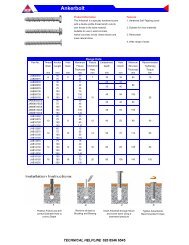
20 | INSTALLATION GUIDANCEHEXAGONAL & COUNTERSUNK (HEAD)DRILLING & PREPARATIONEnsure that holes are drilled in both the fixture and the section according to the drilling guidance below.Please note that clearance holes are slightly larger than standard bolt clearance holes to accommodate the sleeve and cone.SizeClearanceHole Ø Hole Distances Edge Distancesmin td 1min Amin BB+Cmmmmmmmmd 1d 1A B CM8 14 (+1.0 / -0.2) 35 13 B + C > 17.5M10 18 (+1.0 / -0.2) 40 15 B + C > 22.5M12 20 (+1.0 / -0.2) 50 18 B + C > 25.0M16 26 (+2.0 / -0.2) 55 20 B + C > 32.5M20* 33 (+2.0 / -0.2) 70 25 B + C > 33.0* Hexagonal Head onlyINSTALLATION1 Align pre-drilled fixture andGrip the <strong>Hollo</strong>-Bolt collarsection and insert <strong>Hollo</strong>-Bolt a) . with an open ended spanner.2 3 Using a torque wrench,tighten the central bolt tothe recommended torque b) .a) Before tightening, ensure that the materials that are to be connected together are touching.b) See page 22 for tightening torque.Power tools, such as an impact wrench, may be used to speed up the tightening of the <strong>Hollo</strong>-Bolt.However, when using power tools, always complete the tightening process with a torque wrenchto ensure the correct torque is applied to the <strong>Hollo</strong>-Bolt.<strong>Hollo</strong>-Bolt ®www.hollo-bolt.com
INSTALLATION GUIDANCE | 21FLUSH FITEnsure that countersunk holes are drilled in the fixture, and standard holes are drilled in the section, accordingto the drilling guidance below. Please note that clearance holes are slightly larger than standard bolt clearance holes toaccommodate the sleeve and cone.90 o DRILLING & PREPARATIONd 2t 1d 1d 1mmmmmmmmmmmmd 1d 2t 1min Amin BB+CSizeClearanceHole ØCountersunkØ DepthHoleDistancesEdgeDistancesM8 14 (+1.0 / -0.2) 27 6.5 35 13 B + C > 17.5M10 18 (+1.0 / -0.2) 31 6.5 40 15 B + C > 22.5A B CM12 20 (+1.0 / -0.2) 35 7.5 50 18 B + C > 25.0INSTALLATION1 Align pre-drilled fixture andsection and insert <strong>Hollo</strong>-Bolt a) .Apply installation nut andgrip with an open endedspanner.Installation Nut2 3 Using a torque wrench, tightenthe central countersunk bolt tothe recommended torque b) .a) Before tightening, ensure that the materials that are to be connected together are touching.b) See page 22 for tightening torque.Power tools, such as an impact wrench, may be used to speed up the tightening of the <strong>Hollo</strong>-Bolt.However, when using power tools, always complete the tightening process with a torque wrenchto ensure the correct torque is applied to the <strong>Hollo</strong>-Bolt.www.hollo-bolt.com <strong>Hollo</strong>-Bolt ®
DESIGN DATA - CHARACTERISTIC VALUES | 23Characteristic values of tensile and shear resistance for <strong>Hollo</strong>-Bolt taken fromETA-10/0416. For more information visit www.lindapter.com/about/ceFor designing toEurocode 3 standard onlyHOLLO-BOLT HEXAGONALProductCodeNominalSizeTensileF t,Rk(kN)ShearF v,Rk(kN)Material Strengthof Sleeve(N/mm 2 )HB08 M8 23.1 32.9 430HB10 M10 39.6 54.2 430HB12 M12 45.8 71.0 430HB16 M16 84.3 139.0 430HB20 M20 124.0 211.0 390HOLLO-BOLT HEXAGONAL STAINLESS STEELProductCodeNominalSizeTensileF t,Rk(kN)ShearF v,Rk(kN)Material Strengthof Sleeve(N/mm 2 )HBST08 M8 26.8 30.7 500HBST10 M10 46.0 51.0 500HBST12 M12 53.3 65.0 500HBST16 M16 98.0 128.0 500HBST20 M20 154.0 205.0 500HOLLO-BOLT COUNTERSUNK (HEAD)HOLLO-BOLT COUNTERSUNK (HEAD) STAINLESS STEELProductCodeNominalSizeTensileF t,Rk(kN)ShearF v,Rk(kN)Material Strengthof Sleeve(N/mm 2 )ProductCodeNominalSizeTensileF t,Rk(kN)ShearF v,Rk(kN)Material Strengthof Sleeve(N/mm 2 )HBCSK08 M8 23.1 32.9 430HBCSK10 M10 39.6 54.2 430HBCSK12 M12 45.8 71.0 430HBCSK16 M16 84.3 139.0 430HBSTCSK08 M8 26.8 30.7 500HBSTCSK10 M10 46.0 51.0 500HBSTCSK12 M12 53.3 65.0 500HBSTCSK16 M16 98.0 128.0 500HOLLO-BOLT FLUSH FITHOLLO-BOLT FLUSH FIT STAINLESS STEELProductCodeNominalSizeTensileF t,Rk(kN)ShearF v,Rk(kN)Material Strengthof Sleeve(N/mm 2 )ProductCodeNominalSizeTensileF t,Rk(kN)ShearF v,Rk(kN)Material Strengthof Sleeve(N/mm 2 )HBFF08 M8 23.1 32.9 430HBFF10 M10 39.6 54.2 430HBFF12 M12 45.8 71.0 430HBSTFF08 M8 26.8 30.7 500HBSTFF10 M10 46.0 51.0 500HBSTFF12 M12 53.3 65.0 500HOLLO-BOLT BUTTON HEAD / SECURITY* Please contact Lindapter to discuss the available options.ProductCodeNominalSizeTensileF t,Rk(kN)ShearF v,Rk(kN)Material Strengthof Sleeve(N/mm 2 )HBBH/HBFT/HBPR M8 23.1 32.9 430HBBH/HBFT/HBPR M10 39.6 54.2 430HBBH/HBFT/HBPR M12 45.8 71.0 430The characteristic values for the <strong>Hollo</strong>-Bolt listed in the abovetables are for use when designing bolted connections to Eurocode 3only, these are not standard safe working loads.<strong>Hollo</strong>-Bolt lengths 1, 2 and 3 are covered by this ETA 10/0416. The characteristicvalues are used to determine the design resistance of the <strong>Hollo</strong>-Bolt. The designresistance is calculated by dividing the characteristic value by a partial factorγm2. The partial factor is a nationally determined parameter (for example: γm2=1.25 in the UK). For <strong>Hollo</strong>-Bolt safe working loads with a factor of safety of 5:1please refer to the <strong>Hollo</strong>-Bolt tables on Page 22 of this brochure.The characteristic values are valid for the <strong>Hollo</strong>-Bolt assembly itself, in anyconnection detail the design resistance of the connection may be limited to alesser value. For example, when the thickness of the connected component issmall, pull out failure may occur before failure of the <strong>Hollo</strong>-Bolt.Design checks should be carried out on the section member to determine thestatic design resistance. The SCI Greenbook publication P.358 Joints in Steelconstruction, Simple Joints to Eurocode 3 contains a number of checks onthe section. The characteristic values are only valid when the <strong>Hollo</strong>-Bolts areinstalled as per our installation instructions.Joints in Steel Construction - Simple Joints to Eurocode 3The SCI Greenbook publication P.358 Joints in Steel construction, Simple Joints to Eurocode 3 contains a number of checkson the section. The characteristic values are only valid when the <strong>Hollo</strong>-Bolts are installed as per our installation instructions.To obtain further details on the Simple Connections guide please contact:The Steel Construction Institute Tel: +44 (0) 1344 636 525 / Fax: +44 (0) 1344 636 570 / www.steel-sci.comPublished by SCI/BCSA Connections Group. Publication Number: P358 / ISBN 978-1-85942-201-4.www.hollo-bolt.com <strong>Hollo</strong>-Bolt ®
24 | FAQs??YOUR QUESTIONS ANSWERED...Can Lindapter <strong>Hollo</strong>-Bolts be usedin all sizes & shapes of SHS?Yes, the Lindapter <strong>Hollo</strong>-Bolt can be used inall sizes of Structural <strong>Hollo</strong>w Section (SHS)and is suitable for use in those of square,rectangular, circular or elliptical shape.The capacity figures for the Lindapter<strong>Hollo</strong>-Bolts shown in both SCI ‘GreenBooks’ are different to the figuresshown in the Lindapter catalogue.Which figures should I use?The loads shown on page 22 of this brochureare Safe Working Loads, with Lindapter’stypical Factor of Safety of 5:1, and are forgeneral use.For structural use, the loads shown in theSCI design guides are not Safe Working Loads,they are Design Capacities, to be compared incalculations with the structural capacity of thesupporting column wall (SHS).Who is responsible for checking thecapacity of the structural sectionwhen using Lindapter <strong>Hollo</strong>-Bolts?How does the HCF mechanismincrease clamping force?Without the HCF mechanism on the largersizes (M16 & M20), the majority of the preloadin the bolt is transferred into expanding thesleeve. Lindapter’s patented HCF mechanismin the 5-part <strong>Hollo</strong>-Bolt (HCF) allows thesleeve to expand and converts some of thepreload into clamping force to hold theconnection securely together.What is the significance ofincreased clamping force?Clamping force is the compressive forcewhich holds the connection together. An M16or M20 connection using the 5-part <strong>Hollo</strong>-Bolt (HCF) will be held together with a greaterforce than a 3-part product of the same size,and have less movement at safe working load.With the 5-part <strong>Hollo</strong>-Bolt (HCF), a higherload is needed initially to pull the connectionapart.Why don’t you make all <strong>Hollo</strong>-Boltsto the 5-part design?The M16 & M20 sized <strong>Hollo</strong>-Bolt (HCF) wasdesigned specifically for larger structuralconnections that require high clampingforce. The <strong>Hollo</strong>-Bolt M8, M10 & M12 arenot generally used for structural joints andadding the HCF mechanism to these smallersizes would not create a significant advantagewhen compared to the superior performanceof the M16 and M20 <strong>Hollo</strong>-Bolt (HCF).It is the responsibility of a StructuralEngineer to ensure a hollow section hassufficient capacity to take the necessaryloads. Help can be found within eitherof the current SCI/BCSA ‘Green Books’,where P.212 should be used if designingsimple connections to BS5950 whilstP.358 should be used if designing simplejoints to Eurocode 3.Why is there some displacement,even on the <strong>Hollo</strong>-bolt (HCF)?The <strong>Hollo</strong>-Bolt is a ductile connection and thechord face of the hollow section can deflect.The Safe Working Load for the <strong>Hollo</strong>-Bolt hasbeen set at an area of minimal displacement(please view the Load/Displacement graphson page 7).<strong>Hollo</strong>-Bolt ®www.hollo-bolt.com
FAQs | 25Can <strong>Hollo</strong>-Bolts be used in slotted holes?Are Lindapter <strong>Hollo</strong>-Bolts removable?Yes, it is possible to use <strong>Hollo</strong>-Bolts with slottedholes in the outer bracket or end plate as longas there is no horizontal load in the direction ofthe slot. However, the hole in the hollow sectioninto which the <strong>Hollo</strong>-Bolt is to be installed mustbe circular and within the tolerance stated inthis brochure.Can Lindapter <strong>Hollo</strong>-Bolts be sealedto prevent water ingress?Yes. Although the vast majority of Lindapter<strong>Hollo</strong>-Bolts used globally do not use any sealingmethod, special washers have been suppliedon a limited number of occasions. However, it isimportant not to ignore the interface betweenthe structural tube and plate or bracket which isbeing attached.Yes. Although designed as a permanentconnection, it is possible to remove theHexagon and Countersunk (Head) variantsby following this procedure:1. Grip the <strong>Hollo</strong>-Bolt collar with an openended spanner / wrench to prevent thecollar from rotating.2. Use an impact wrench / torque wrenchto remove the bolt (anti-clockwiserotation).3. <strong>Hollo</strong>-Bolt sizes M8, M10 & M12 only:remove the sleeve by prying the collarwith a pinch or crow bar. Note: thisadditional step is not required to removethe M16 & M20 due to their 5-part design.The special Security Button Head <strong>Hollo</strong>-Bolt is designed so that it cannot be easilyremoved without the Security Key.Can I use stainless steel <strong>Hollo</strong>-Bolts to connectbrackets to mild steel hollow section?Can I use the <strong>Hollo</strong>-Bolt to connecttimber to steel?Where possible the best option is to ensurethat the section, bracket and <strong>Hollo</strong>-Bolt are allproduced from the same material, or are closeto each other on the galvanic corrosion chart.If stainless components are in contact with mildsteel, bimetallic corrosion will be accelerated.Yes, although it is important to ensure thatthe timber is capable of withstanding theclamping force created when applying torqueto the <strong>Hollo</strong>-Bolt. In some cases a spreaderwasher can be used under the collar of the<strong>Hollo</strong>-Bolt to distribute the force over agreater area.Can I use <strong>Hollo</strong>-Bolts in concrete filled sections?The <strong>Hollo</strong>-Bolt was designed for connecting tostructural sections and needs an obstacle freearea for the sleeve to expand. Once thecomponent is installed correctly the sectioncan then be filled with concrete.@IF YOU HAVE ANY FURTHER QUESTIONSPLEASE CONTACT enquiries@lindapter.comWhy aren’t all the head variantsavailable in Hot Dip Galvanised finish?When components with a hexagon socket areHot Dip Galvanised, the high build up of zinc inthe recess results in a reduced A/F dimensionmeaning that a standard Allen/Hexagon Keyno longer fits correctly. This would make itvery difficult for the installer to apply therequired torque to ensure the <strong>Hollo</strong>-Boltexpands correctly.www.hollo-bolt.com <strong>Hollo</strong>-Bolt ®
8-off HB20-1Endplate 1EndPlate 1RHS 300x200x10RHS 400x200x10SECTION A-A4-off HB20-1Endplate 2EndPlate 2SHS160x160x10ABADETAIL BInstalled<strong>Hollo</strong>-BoltGENERAL NOTES:1. DO NOT SCALE THIS DRAWING2. DIMENSIONS ARE IN MM3. TOLERANCES:4. ANGULAR: BEND5. THIS DRAWING AND THE COPYRIGHTTHEREIN ARE THE PROPERTY OF LINDAPTERINTERNATIONAL. IT IS ISSUED ON THECONDITION THAT IT MUST NOT BE USED,COPIED, DISTRIBUTED OR EXHIBITEDWITHOUT WRITTEN PERMISSION ANDCONSENT. THE DRAWING MUST ALSONOT BE USED FOR ANY OTHER PURPOSETHAN WHICH IT IS ISSUED.DRAWING NOTES:REV. DESCRIPTIONBY DATEDRAWING TITLEHB20-1 <strong>Hollo</strong>-BoltApplicationGeneral Arrangementwww.lindapter.comEurocode 3 Technical Data:CUSTOMERENQUIRY N.Jacobs16525-IPDRAWNDATECHECKED- Tightening Torque is 300NmIP 13/02/12MK- Endplate 1 Tensile Load is 1000kN (Characteristic Value)SCALE:WEIGHT:NOT TO SCALE- Endplate 2 Tensile Load is 500kN (Characteristic Value) DWG. NO. REV.SW2698-IP 026 | LINDAPTER SERVICE & PRODUCTSTECHNICAL SUPPORTThe comprehensive technical support from Lindapter’sexperienced engineers ensures an efficient specificationprocess with a free connection design service and bills ofmaterials upon request. Lindapter’s philosophy is to deliverthe highest quality at every stage of the service, from initialconnection design to installation guidance.> Free connection design based on your requirement> Optimised solution for cost and performance> Bespoke drawings delivered in 2D and interactive 3D formats> CAD files for import into major software applications> Contractor trainingENGINEERED SOLUTIONSLindapter’s unique R&D capability facilitates abespoke product development service, passionatelyreferred to as ‘Engineered Solutions’.R&D FacilityOne of two1000 kNtesting machines^The service offered to clients includes:> Design and development of customised products> Full strength and performance analysis> Thoroughly tested with detailed reports> Manufactured to Lindapter’s exacting standards^ Type 1055Bespoke product designed to fit solid plateflooring to open grid flooring for Amec/ShellLINDIBOLT ® 2In addition to the <strong>Hollo</strong>-Bolt,Lindapter also invented the Lindibolt.The self heading expansion bolt issuitable for connecting steelworkto hollow-sections, tubes and whereaccess is available from one side only.The Lindibolt 2 uses a standardclearance hole for convenience.SetscrewLocknutNutWasherMain BodyConePlease refer to the full Lindapter catalogue for further information.<strong>Hollo</strong>-Bolt ®www.hollo-bolt.com
16SG iron, hot dip galvanisedTYZXVType AFHolds the bolt head captive(bolt grade 8.8)RecessNoseSkirtTailType AF & AFWConverts recessed clampto flat top clampType AFWType AF & AFW (inverted)Holds the bolt head captive (bolt grade10.9 with larger hexagon size M12 - M20)Type AFWTypical Applications(see also page 36-39)A high friction clamp with a recessed top to hold the bolt head captive while the nut istightened. Washer Type AFW available (see illustrations above and page 18). The skirtprevents the clamp rotating during installation. The tail of the AF spans across slottedholes. Suitable for flanges up to 10°, ideal for S-beams. The clamp can be combinedwith Type CF.For correct tail length/packing combinations, please see page 19. The Type AFis compatible with Grade 8.8 and 10.9 bolts: please refer to the table below forperformance comparisons.Safe Working Loads(5:1) Factor of Safety (2:1) DimensionsProduct Bolt Tensile / 1 Bolt Frictional 1) / 2 Bolts Tightening Tail Length V T2)Code Z Grade Painted Steelwork Galv. Steelwork Torque Y X short medium Type AF Type AF with AFW WidthkN kN kN Nm mm mm mm mm mm mm mmAF12 M12 8.8 8.5 3.4 3.9 90 27 27 5 12.5 17 22 39AF16 M16 8.8 16.0 8.0 10.0 240 35 37 8 15 22 27 49AF20 M20 8.8 26.3 13.0 16.0 470 40 39 10 18 25 31 56AF24 M24 8.8 40.0 24.0 30.0 800 48 60 15 30 32 42 824)AF12 M12 10.9 10.0 4.0 5.2 130 27 27 5 12.5 17 22 394)AF16 M16 10.9 19.5 11.0 12.0 300 35 37 8 15 22 27 494)AF20 M20 10.9 30.0 20.0 25.0 647 40 39 10 18 25 31 564)AF24 M24 10.9 62.53) 28.0 35.0 1000 48 60 15 30 32 42 821) Frictional Load figures are based on Type AF and Location plates in hot dip galvanised finish calculated against slip (movement exceeding 0.1mm).2) Shot blast and painted steelwork3) 3.2:1 factor of safety4) For HR or HV bolts (hot dip galvanised and lubricated) please refer to manufacturers’ recommendation for torque figures.Order example: AF12 shortSG iron, hot dip galvanisedEuropean Patent No: EP1834099Registered in European Community under design numbers:000654462-0001, 000654462-0002, 000654462-0003, 000654462-0004NoseYZmin tXmin TVAnti-rotation markingsLegsA high friction clamp which hooks over the flanges of beams, anglesand channels. Lindapter markings act as a unique anti-rotationdevice. The clamp can be combined with all Lindapter Girder Clampproducts, including the Type AF.YZmax tXmax TTypical Applications (see also page 36-39)Safe Working Loads(5:1) factor of safety (2:1)Product Bolt 8.8 Tensile / 1 Bolt Frictional 1) / 2 Bolts Tightening Dimensions2)Code Z Painted Steelwork Galv. Steelwork Torque Y X t T V WidthkN kN kN Nm mm mm mm mm mm mmCF12 M12 8.5 3.4 3.9 90 32 14 6 - 13 21 - 29 25 46CF16 M16 16.0 8.0 10.0 240 44 18 8 - 16 25 - 33 32 56CF20 M20 26.3 13.0 16.0 470 53 22 10 - 19 30 - 41 45 65Order example: CF12CF Combinations with other Lindapter ClampskN kN kN Nm3)CF / A M12 5.8 0.7 0.7 693)CF / A M16 7.3 1.5 1.7 1473)CF / A M20 14.7 3 3.0 285CF / AF M12 8.5 3.4 3.9 90CF / AF M16 16.0 8.0 10.0 240CF / AF M20 26.3 13.0 16.0 4701) Frictional load figures are based on Type CF and location plate in HDG finish calculated against slip (movement exceeding 0.1mm).2) Shot blast and painted steelwork3) Also applies to Type B, BR, LR, D2 or D317LINDAPTER PRODUCTS | 27FULL PRODUCT RANGELINDAPTER CATALOGUEAVAILABLENOW!WHAT’S INSIDE?STEELWORK FIXINGSLindapter has pioneered a unique & provenconcept: innovative clamping systems thateliminate the need to weld or drill, reducinginstallation time & labour costs.Technical Innovation inSteelwork ConnectionsCAVITY FIXINGSThe range consists of the legendary<strong>Hollo</strong>-Bolt and Lindibolt, creating simple,cost-effective connections for SHS andother hollow sections.Established 1934COMPOSITE DECKING FIXINGSEasy to install connections to fit inside thedovetail shaped re-entrant channel of allmajor decking profiles. Ideal for supportingHVAC equipment and cable trays withoutweakening the decking profile.Type AF Steelwork Fixings 1Type AFType CF Steelwork Fixings 1Type CFSUPPORT FIXINGSLindapter provides a wide range ofconnection solutions for suspendingbuilding services, such as pipe work,sprinklers & suspended ceilings, fromstructural or supporting steel.Tel: +44 (0) 1274 521444 © Lindapter International 2012 www.lindapter.comTel: +44 (0) 1274 521444 © Lindapter International 2012 www.lindapter.comFLOOR FIXINGSLindapter’s unique no-weld no-drill conceptextends to the connection of steel flooring.Open bar grating & chequer plate flooringcan be installed by one person from above.Request your copy today by contacting@ enquiries@lindapter.comwww.hollo-bolt.com <strong>Hollo</strong>-Bolt ®
HB-UK-12a