Part 1 - Fischer Panda Generators Inc.
Part 1 - Fischer Panda Generators Inc.
Part 1 - Fischer Panda Generators Inc.

You also want an ePaper? Increase the reach of your titles
YUMPU automatically turns print PDFs into web optimized ePapers that Google loves.
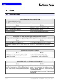
Operation manual - <strong>Part</strong> 1Description of the generator and operation manual<strong>Panda</strong> PMS 8 „Mini“Super silent technology120 V - 60 Hz / 8kWIcemaster <strong>Fischer</strong> <strong>Panda</strong>
25 20 10 10 10since 1977Icemaster GmbHsince 1978<strong>Fischer</strong> Marine<strong>Generators</strong>since 1988Conclusion <strong>Fischer</strong> -Icemaster GmbHsince 1988100 % water cooled<strong>Panda</strong> generatorssince 1988<strong>Panda</strong> Vehicle<strong>Generators</strong><strong>Fischer</strong> <strong>Panda</strong>FISCHER GENERATORS have been manufactured since 1978 and are a well-known brand for first class diesel generatorswith especially effective sound-insulation.<strong>Fischer</strong> has been one of the leading manufacturers in respect of quality and know-how during this period.FISCHER, as the worldwide manufacturer of modern marine diesel generators, developed the Sailor-Silent series forexample and produced a GFK sound-insulated capsule as early as 1979 and the basis for new generator technology.The companies <strong>Fischer</strong> and Icemaster amalgamated under the direction of Icemaster in 1988, in order to concentrateon the development of new products. Production was moved to Paderborn.The amalgamation of the two qualified companies led to the development of a complete new programme within a shortspace of time. The aggregates developed at that time set new technological standards worldwide.The aggregates became more efficient and powerful than other aggregates in the same nominal performance range,because of the improved cooling. <strong>Panda</strong> generator demonstrated its superiority in several tests by renowned institutesand magazines during the past years. The patented VCS (voltage Control System) means it can meet all demandsincluding motor speed. The start-booster (ASB) means <strong>Panda</strong> generators meet the highest demands in respect ofvoltage stability and starting values A <strong>Panda</strong> generator, with the same drive motor, produces 15% more effective outputthan the majority of conventional generators. This superiority in efficiency also ensures a fuel saving to the same extent.The 100% water-cooled <strong>Panda</strong> Aggregate are currently manufactured in the performance range from 2 to 100 kW invarious versions. Fast running motors are preferred for performances up to approx 30 kW (Nominal speed 3000 rpm).The heavier slow runners are preferred for the higher range. The fast running aggregates have proved themselvesmany times for many uses, that they meet the demands in quality of yachts and vehicles, and offer space and weightsaving of 50% compared to slow running generators.In addition to the <strong>Panda</strong> series, Icemaster also supply the super compact high-tech sound-insulated battery chargingaggregate from the DC/AC <strong>Panda</strong> AGT series, which is a very interesting solution for the production of mobile power.The new HTG-alternators ensure that a charging rate of 285 amps is achieved that was scarcely thought possible forthis compact construction. This alternator replaces a separate shipboard generators (constant 230 volts AC with up to3500 kW from the main machine)ICEMASTER GmbH, 33104 Paderborn, reserves all rights regarding text and graphics. Details are given to the best of our knowledge. No liability is accepted for correctness.Technical modifications for improving the product without previous notice may be undertaken without notice. Before installation, it must be ensured that the Pictures,diagrams and related material are applicable to the aggregate supplied. Enquiries must be made in case o doubt.ii
CALIFORNIAProposition 65 WarningDiesel engine exhaust and some of its constituentsare known to the State of California to cause cancer,birth defects, and other reproductive harm.Attention, Important Directions regarding Operation!1. The installation certificate must be completed when taken into use, and certified by a signature.2. The installation certificate must be despatched within two weeks of use to ICEMASTER.3. The official guaranty confirmation will be completed by ICEMASTER after receipt and sent to the customer.4. A guaranty must be shown to make any claims.Claims against the guaranty will not be accepted of the above said instructions are not, or only partially, carried out.Manufacturer declaration in terms of the machine guideline 98/37/EG .The generator is in such a way developed that all assembly groups correspond to the CE guidelines. If machine guideline98/37/EG is applicable, then it is forbidden to bring the generator into operation until it has been determinedthat the system into which the generator is to be installed in also corresponds to the regulations of the machine guideline98/37/EG. This concerns among other things the exhaust system, cooling system and the electrical installation.The evaluation of the "protection against contact" can only be accomplished in connection with the respectivesystem. Likewise among other things responsibility for correct electrical connections, a safe ground wire connection,foreign body and humidity protection, protection against humidity due to excessive condensation as well as the overheatingthrough appropriate and inappropriate use in its installed state on the respective machine lies within theresponsibility of those who undertake installation of the generator in the system.Technical Support per Internet:info@fischerpanda.comiii
Table of contentsA The <strong>Panda</strong> Generator .........................................................................................................3A.1 Description of the Generator ................................................................................................ 3A.1.1 Right Side View......................................................................................................................... 3A.1.2 Left Side View ........................................................................................................................... 4A.1.3 Front View ................................................................................................................................. 5A.1.4 Back View.................................................................................................................................. 6A.1.5 View from above........................................................................................................................ 7A.2 Details of functional units .................................................................................................... 8A.2.1 Remote control panel ................................................................................................................ 8A.2.2 Components of Cooling System (Seawater) ............................................................................. 9A.2.3 Components of Cooling System (Freshwater) ........................................................................ 10A.2.4 Components of the fuel system............................................................................................... 14A.2.5 Components of combustion air................................................................................................ 16A.2.6 Components of the electrical system ...................................................................................... 19A.2.7 Sensors and switches for operating surveillance .................................................................... 22A.2.8 Components of the oil circuit ................................................................................................... 24A.2.9 External components............................................................................................................... 26A.3 Operation manual ................................................................................................................ 27A.3.1 Preliminary remark .................................................................................................................. 27A.3.2 Daily routine checks before starting ........................................................................................ 28A.3.3 Starting Generator................................................................................................................... 29A.3.4 Stopping the Generator ........................................................................................................... 30A.3.5 Starting the Generator by a „Failure bypass switch“ ............................................................... 30<strong>Panda</strong> PMS 8mini - Table of contents - Page 1
Page 2<strong>Panda</strong> PMS 8mini - Table of contents
The <strong>Panda</strong> GeneratorA. The <strong>Panda</strong> GeneratorA.1 Description of the GeneratorA.1.1 Right Side View0102040305080609071011121314151617 18 192001. Cooling water filler neck02. Water-cooled exhaust manifold03. 12V DC-alternator04. Exhaust manifold thermo-switch05. V-belt for DC-alternator and cooling water pump06. Magnetic switch for starter motor07. Generator housing with coil08. Oil pressure switch09. Exhaust connection10. Injectior for cooling water11. Engine oil filter12. Starter motor13. Cooling water backflow pipe14. Generator Klemmkasten15. Connection for external cooling water expansion tank16. Sound cover - base part17. Engine connecting flange18. Exhaust thermo-switch19. Exhaust hose connection20. Connection for external ventilation valve<strong>Panda</strong> PMS 8mini - Chapter A: The <strong>Panda</strong> Generator Page 3
The <strong>Panda</strong> GeneratorA.1.2 Left Side View2406010207080904050310111213141517 18 19 20 21 22 231601. Charge control for DC-alternator02. Air suction housing with air filter03. Actuator for speed control04. Generator housing with coil05. Cooling water connection block06. Ventilation screw thermostat housing07. Ventilation screw internal cooling water pump08. Pulley for internal cooling water pump09. Fuel solenoid valve10. Ventilation screwfuel solenoid valve11. Adjusting screw12. Stop screw for setting maximum speed13. Seawter pump14. Oil dipstick15. Fuel filter with water separator16. Seawter inlet17. Engine connecting flange18. Flat fuse 15Amps (blue)19. Flat fuse 25Amps (white)20. Starter relay Ks21. Pre-glow relay (glow plugs) K222. Fuel pump start relay K323. Failure bypass switch24. Cylinder head thermo-switchPage 4<strong>Panda</strong> PMS 8mini - Chapter A: The <strong>Panda</strong> Generator
The <strong>Panda</strong> GeneratorA.1.3 Front View010807020309050411100612 13 14 15 16 17 18 19 20 21 2201. Ventilation screw internal cooling water pump02. Fuel solenoid valve03. Pulley for internal cooling water pump04. Freshwater intake pipe05. Seawter pump06. Fuel filter with water separator07. Ventilation screw thermostat housing08. Thermostat housing with thermostat set09. 12V DC-alternator10. V-belt for DC-alternator and internal cooling water pump11. Engine oil filter12. Seawter inlet13. Fuel intake connection14. Fuel backflow connection15. Fuel pump cable (2x1,5mm²)16. Oil drain hose17. Remote control panel cable (12x1mm²)18. Electronic Voltage Control cable VCS (5x1mm²)19. AC-Control box cable20. Load21. Battery minus (-)22. Battery plus (+)<strong>Panda</strong> PMS 8mini - Chapter A: The <strong>Panda</strong> Generator Page 5
The <strong>Panda</strong> GeneratorA.1.4 Back View0102120304050608070910 1101. Cooling water filler neck02. Exhaust manifolf thermo-switch03. Air suction housing with air filter04. Charge control for DC-alternator05. Generator front plate06. Oil flow glas07. Thermo switch at oil cooled bearing08. Cooling water connection block09. Intake external cooling water expansion tank10. Backflow external cooling water expansion tank11. External ventilation valve connection12. Water-cooled exhaust manifoldPage 6<strong>Panda</strong> PMS 8mini - Chapter A: The <strong>Panda</strong> Generator
The <strong>Panda</strong> GeneratorA.1.5 View from above01030208150409100506110712 13 1401. Intake external cooling water expansion tank02. Cooling water filler neck03. Exhaust manifold thermo-switch04. Engine oil filler neck05. Air suctin housing with air filter06. Cylinder head thermo-switch07. Charge control for DC-alternator08. 12V DC-alternator09. Thermostat housing with thermostat set10. Ventilation screw thermostat housing11. Ventilation screw internal cooling water pump12. Injection nozzle13. Fuel solenoid valve14. Ventilation screw fuel solenoid valve15. Backflow external cooling water expansion tank<strong>Panda</strong> PMS 8mini - Chapter A: The <strong>Panda</strong> Generator Page 7
The <strong>Panda</strong> GeneratorA.2 Details of functional unitsA.2.1 Remote control panelThe remote control panel is necessary to control the generator and to evaluate the motor/generatorproperties. The generators will automatically cutout if it does not run as required. The generatormay not be run without the remote control panel.01 02 03 04 0506 0708111409 1015 12 1301. Warning light for cooling water temperature02. Warning light for leak (Sensor optional)03. Warning light for AC fault04. AC-Voltage control light05. Warning light for windings temperature06. Warning light for oil pressure07. Battery charge voltage 12Volt -DC control lamp08. LED display for pre-glow09. Pre-glow button (Heat)10. Generator „Start“-button11. Control light for Generator-“Start“12. Generator „Off“ button13. Generator „On“ button14. Generator „Stand by“ control light15. Running hours counterFig. A.1: Remote control panelAutomatic Start OptionAn automatic start option is available as an accessory. This includes a separate control board,which is connected to the main remote control board panel. The Automatic Start Option allowsthe generator to be started by means of an external signal (i.e Battery Monitor). A speed gaugeand a sensor for speed pick-up are additionally necessary in addition to the automatic startoption. (See Component Automatic Start)Page 8<strong>Panda</strong> PMS 8mini - Chapter A: The <strong>Panda</strong> Generator
The <strong>Panda</strong> GeneratorA.2.2 Components of Cooling System (Seawater)Seawater intakeThe figure shows the supply pipes for thegenerator. The connection neck for theseawater connection is shown on the lefthand side. The cross-section of the intakepipe should be nominally larger than thegenerator connection.Fig. A.2: Seawater intakeSeawater impeller pumpThe seawater pump is fitted with a rubberimpeller. This pump is self-inductive. If, forexample, you forget to open the seavalve, then you must expect the impellerto be destroyed after a short period oftime. It is recommended to store severalimpellers on board as spare parts.Fig. A.3: Seawter inpeller pumpHeat exchangerSeparates the seawater system from thefreshwater system.Fig. A.4: Heat exchanger<strong>Panda</strong> PMS 8mini - Chapter A: The <strong>Panda</strong> Generator Page 9
The <strong>Panda</strong> GeneratorVentilation valveA siphon must be installed if the generatorsinks below the water line because of therocking of the boat, even if it is only for ashort period of time. A hosepipe on thegenerator casing has been produced forthis. Both connecting pieces are bridgedby a formed piece of hose.Fig. A.5: Connection external ventilation valveCooling water injector nozzleThe injection point for the marine generatorwater-cooled exhaust system is situatedat the exhaust connection piecesThe exhaust connections must be regularlychecked for signs of corrosion.Fig. A.6: Cooling water injector nozzleA.2.3 Components of Cooling System (Freshwater)The cooling water filler necks situated atthe water-cooled manifold are only used,when the generator is initially started.Since the generator is normally alreadyfilled with cooling water, these componentsare only by the user, if repairs are tobe carried out. Topping up with coolingwater may only carried out at the externalcooling water compensation tank. Notethat the water level in the cooling watercompensation tank is only 20% of the volumein a cold state.Fig. A.7: Cooling water filler neckPage 10<strong>Panda</strong> PMS 8mini - Chapter A: The <strong>Panda</strong> Generator
The <strong>Panda</strong> GeneratorFreshwater backflowThe cooling water is fed to the heatexchanger from the water-cooled manifoldby means of the pipe shown in the diagram.Fig. A.8: Freshwater backflowVentilation pipeThe ventilation pipe at the water-cooledexhaust manifold leads to the externalexpansion tank. This pipe only serves asa ventilation pipe, if both pipes are to beconnected to the external expansion tank(ventilation pipe and intake pipe).Fig. A.9: Ventilation pipeHose connection pieces for the externalexpansion tankThe external expansion tank is connectedby two hose connections. The connectingpieces shown here serves as constantventilation for the water-cooling system.In case the external expansion tank isconnected with two hoses, the system willventilate itself. In this case, additional ventilationis only necessary when the generatoris initially filled, or if the cooling wateris not circulating.Fig. A.10: External expansion tank<strong>Panda</strong> PMS 8mini - Chapter A: The <strong>Panda</strong> Generator Page 11
The <strong>Panda</strong> GeneratorHeat exchangerSeparates the seawater system from thefreshwater system.Fig. A.11: Heat exchangerCooling water connection blockThe cooling water is fed to the generatorand drained via the cooling water connectionblock. The cooling water connectionblock consists of an aluminium alloy,which can behave like a sacrificial anode.Fig. A.12: Cooling water connection blockInternal cooling water pumpThe diesel motor cooling water pump (seearrow) aids the circulation of the internalfreshwater system.Fig. A.13: Internal cooling water pumpPage 12<strong>Panda</strong> PMS 8mini - Chapter A: The <strong>Panda</strong> Generator
The <strong>Panda</strong> GeneratorCooling water intakeA.) To the thermostat housingB.) From the external expansion tankThe intake pipe from the external coolingwater expansion tank is connected to thepoint shown with „B“.ABFig. A.14: Internal cooling water pumpVentilation screw cooling water pumpThe ventilation screw above the coolingwater pump casing may not be opened,whilst the generator is running. If thisoccurs by mistake, air will be drawnthrough the opening. Extensive ventilationof the whole system is then necessary.Fig. A.15: Ventilation screw cooling water pumpVentilation screw thermostat housingThe ventilation screw on the thermostathousing should occasionally be openedfor control purposes. Standing machineryshould principally carry out ventilating.Fig. A.16: Ventilation screw thermostat housing<strong>Panda</strong> PMS 8mini - Chapter A: The <strong>Panda</strong> Generator Page 13
The <strong>Panda</strong> GeneratorWater-cooled exhaust manifoldThe manifold is cooled by means of theinternal cooling system (freshwater). Thecooling water filler necks on the casing ofthe manifold may not be opened. Thesecooling water necks are only required tofill the motor with cooling water in cases ofrepair. The normal cooling water controlsmay only be carried out at the externalexpansion tank.Fig. A.17: Water-cooled exhaust manifoldA.2.4 Components of the fuel systemExternal fuel pumpThe <strong>Panda</strong> generator is always suppliedwith an external, electrical (12 V of DC) fuelpump. The fuel pump must be alwaysinstalled in the proximity of the tank. Theelectrical connections with the lead plannedfor it are before-installed at the generator.Since the suction height and thesupply pressure are limited, it can besometimes possible that for reinforcementa second pump must be installed.Fig. A.18: External fuel pumpConnecting pieces for the fuel pipe1. Fuel intake2. Fuel backflow1 2Fig. A.19: Fuel connectionsPage 14<strong>Panda</strong> PMS 8mini - Chapter A: The <strong>Panda</strong> Generator
The <strong>Panda</strong> GeneratorFuel filterA consequential filtering of fuel is especiallyimportant for all marine systems. A finefilter, which is firmly attached to the insideof the sound insulation capsule for themarine version, is supplied on delivery, andloose for other makes. In all cases a furtherpre-filter with water separator must beinstalled. See directions for fuel filter installation.Fig. A.20: Fuel filterFuel solenoid valveThe fuel solenoid valve opens automaticallyif „START“ is pressed on the remotecontrol panel“. The solenoid closes, if thegenerator is switched to „OFF“ position. Ittakes a few seconds before the generatorstops. If the generator does not start ordoes not run smoothly (i.e. stutters), ordoes not attain full speed, then the causeis fore-mostly the solenoid.1) Fuel solenoid valve2) Ventilation screw solenoid valve3) Magnetic coil231Fig. A.21: Fuel solenoid valveInjection nozzlesIf the engine does not start after the ventilation,the fuel injection lines must be deaeratedindividually.Fig. A.22: Injection nozzles<strong>Panda</strong> PMS 8mini - Chapter A: The <strong>Panda</strong> Generator Page 15
The <strong>Panda</strong> GeneratorGlow plugsThe glow plugs serve the pre-chamber forthe heating with cold start. The heat-treatfixture must be operated, if the temperatureof the generator is under 16°C. Thisis practically with each start the case. Theheat-treat fixture may be held down alsoduring start and favoured the starting procedure.Fig. A.23: Glow plugsA.2.5 Components of combustion airAnsaugluftzufuhr am GehäuseThe sound cover for the marine generatoris normally provided at the lower surfacewith drillings, through which the combustionair can influx.It must be consistently paid attention thatthe generator is installed in such a waythat from down no water can arrive intothe proximity of these air openings. (minimumdistance 150 mm)Fig. A.24: Combustion air intakeDrillings for combustion air at thesound coverDrillings at the lower surface of the soundcover serve the admission of fresh air forthe entrance. It must be safe that no seawateror other water can come into thisrange of this openings. If air is sucked inthrough these openings, water can penetratealso into the sound cover.Fig. A.25: Sound cover drillingsPage 16<strong>Panda</strong> PMS 8mini - Chapter A: The <strong>Panda</strong> Generator
The <strong>Panda</strong> GeneratorAir suction housing with 12V DCcharge controlThe shown air suction housing shows the12V DC charge control (pos. 2) at theexterior. This charge control is to be chekked,if the 12V DC voltage is not correct.If the cover (pos. 1) is removed, the insideof the air suction housing becomes visible.In these air suction housings is a filter element.At the marine version the filter isnormally not changed. It should be chekkedonce in a while.12Fig. A.26: Air suction housingAir suction housing with air filter setThe figure shows the air filter element inthe air suction housing. However thereturn pipe of the crank case exhaustflows also into the air suction housing, itcan be faced with older generators and/orwith engines on high running time that oelvapors affect the air filter. Therefore ancheck is advisable once in a while.Fig. A.27: Air filter setCombustion chamber intake elbowThe figure shows the induction elbow atthe combustion engine. At the front of thisinduction elbow you can see the hoseconnection between air suction housingsand induction elbow. The air filter must bechecked, if this hose pulls together at operation.Fig. A.28: Combustion chamber intake elbow<strong>Panda</strong> PMS 8mini - Chapter A: The <strong>Panda</strong> Generator Page 17
The <strong>Panda</strong> GeneratorExhaust elbowOn the back of the engine is the watercooledexhaust elbow. On the top side thepipe union for the internal seawater circuitis to be seen and the filler neck for thecooling water. This cooling water fillerneck is used only at first filling. Control ofthe cooling water and if necessary refilltakes place at the external cooling waterexpansion tank.Fig. A.29: Exhaust elbowExhaust connection at the exhaustelbowSeawater from the external cooling circleis fed here.Fig. A.30: Exhaust connectionExhaust outletConnect the exhaust pipe with the waterlock.Fig. A.31: Exhaust outletPage 18<strong>Panda</strong> PMS 8mini - Chapter A: The <strong>Panda</strong> Generator
The <strong>Panda</strong> GeneratorA.2.6 Components of the electrical systemConnection starter battery1. Cable for starter battery (plus)2. Cable for starter battery (minus)During the connection to the starter batteryit must be always ensured that thecontact is perfectly guaranteed.21Fig. A.32: Cable for starter batteryMain powerAt the front of the sound cover is also thewithdrawal for the cable for the mainpower. Depending upon type of the generatorare here also the cables for the connectionof the external condensers (seefor this the connection diagram for the AC-Control box!)Fig. A.33: Main powerElectrical connections for controlAt the front of the generator also all remainingcables for the electrical connectionsare depending upon type. The allocationof the connections result from the plan forthe AC-Control box. See here:1 2341. Fuel pump2. Remote control panel3. VCS4. AC-Control-BoxFig. A.34: Elektrical connections<strong>Panda</strong> PMS 8mini - Chapter A: The <strong>Panda</strong> Generator Page 19
The <strong>Panda</strong> GeneratorStarter motor21. Starter motor and2. Solenoid switchThe Diesel engine is electrically started.On the back of the engine is accordinglythe electrical starter with the solenoidswitch.1Fig. A.35: Starter motorActuator for speed regulationThe generator voltage is determined byprogressive speed control through "VCS"in conjunction with the speed actuator.Speed increases with increasing load.Fig. A.36: ActuatorBlind plug for speed sensorAll <strong>Panda</strong> generators can be equippedwith an external automatic start. For theoperation of this automatic starting systema separate speed sensor is necessary. Atsome models the speed sensor is standardinstalled. At other models the openingfor the speed sensor is locked by aplug.Fig. A.37: Blind plugPage 20<strong>Panda</strong> PMS 8mini - Chapter A: The <strong>Panda</strong> Generator
The <strong>Panda</strong> GeneratorDC-alternatorAll <strong>Panda</strong> generators from <strong>Panda</strong> 6.000are provided with its own charge systemfor the 12V DC mains. This DC-alternatoris powered over a v-belt together with theinternal cooling water pump.The 12V charge system may be used onlyfor the generator-own starter battery.Fig. A.38: DC-alternatorCharge control for DC-alternatorThe voltage regulator for the 12V DCalternatoris on the back of the air suctionhousing. The housing is formed for coolingpurposes. The voltage regulator maynot be covered from the outside. The surfacemust be accessible for the cooling.Fig. A.39: Charge controlGenerator power terminal boxAt the back of the generator is the generatorpower terminal box. In this box theelectrical connection points of the ACgenerator are connected. Here is also thebridge for the protective grounding of thegenerator. The cover may only be removed,if it is guaranteed that the generatorcannot be inadvertently started.Fig. A.40: Generator power terminal box<strong>Panda</strong> PMS 8mini - Chapter A: The <strong>Panda</strong> Generator Page 21
The <strong>Panda</strong> GeneratorTerminal block for remote control cablewith fuses and power relaisKsK2K3F1 fuse 15A for DC wiringF2 fuse 25A for starter relayKs power relais for StarterK2 power relais for Glow plugsK3 power relais for Fuel pumpF1F2Fig. A.41: Terminal blockA.2.7 Sensors and switches for operating surveillanceThermo-switch at cylinder headThe thermo-switch at the cylinder headserves the monitoring of the generatortemperature. All thermo-switches for thegenerators from <strong>Panda</strong> 6.000 upward aretwo-pole and laidout as "openers".Fig. A.42: Thermo-switch at cylinder headThermo-switch at watercooled exhaustelbowAt some models a thermo-switch is also atthe water-cooled exhaust elbow. Thisthermo-switch serves only for the additionalmonitoring. He is partly no moreinstalled with the recent models.Fig. A.43: Thermo-switch at exhaust elbowPage 22<strong>Panda</strong> PMS 8mini - Chapter A: The <strong>Panda</strong> Generator
The <strong>Panda</strong> GeneratorThermo-switch at exhaust connectionIf the impeller pump drop out and deliveresno more seawater, the exhaust connectionbecomes extremely hot.Fig. A.44: Thermo-switch at exhaust connectionThermo-switch in the generator coil1. Generator coil2. Thermo-switch3. HousingFor the protection of the generator coilthere are two thermo-switches inside thecoil, which are for inserted parallel andsafety's sake independently from eachother.123Fig. A.45: Coil thermo-switchThermo-switch in the generator coil1. Generator coil2. Thermo-switch3. HousingFor the protection of the generator coilthere are two thermo-switches inside thecoil, which are for inserted parallel andsafety's sake independently from eachother.Fig. A.46: Coil thermo-switch<strong>Panda</strong> PMS 8mini - Chapter A: The <strong>Panda</strong> Generator Page 23
The <strong>Panda</strong> GeneratorOil pressure switchIn order to be able to monitore the lubricatingoil system, an oil pressure switch isbuilt into the system. The oil pressureswitch is on the back of the engine (beforethe electrical starter).Fig. A.47: Oil pressure switchFailure bypass switchThe failure bypass switch offers the possibilityof starting the generator if the electricalcontrol switched off due to an error inthe cooling system by overheating.Fig. A.48: Failure bypass switchA.2.8 Components of the oil circuitOil filler neck with capNormally the filler neck for the engine oilis on the top side of the valve cover. Atnumerous generator types a second fillerneck is attached additionally at the operatingside. Please pay attention that the fillernecks are always well locked afterfilling in engine oil.Consider also the references to theengine oil specification.Fig. A.49: Oil filler neck with capPage 24<strong>Panda</strong> PMS 8mini - Chapter A: The <strong>Panda</strong> Generator
The <strong>Panda</strong> GeneratorOil dipstickAt the dipstick the permissible level is indicatedby the markings "maximum" and"minimum". The engine oil should benever filled up beyond the maximum conditions.Fig. A.50: Oil dipstickOil filterThe oil filter should be exchanged with anoil change.Fig. A.51: Oil filterOil drain hoseThe <strong>Panda</strong> generator is equipped that theengine oil can be drained over an drainhose. The generator should be alwaysinstalled therefore that a collecting basincan be set up deeply enough. If this is notpossible, an electrical oil drain pump mustbe installed.Note: Lubricating oil should be drained inthe warm condition!Fig. A.52: Oil drain hose<strong>Panda</strong> PMS 8mini - Chapter A: The <strong>Panda</strong> Generator Page 25
The <strong>Panda</strong> GeneratorA.2.9 External componentsAC-Control boxFor the operation of the generator a AC-Control box is necessary. This AC-Controlbox contains electronics for the VCS controlas well as different monitoring elementsand the capacitors necessary forthe excitation of the generator.Fig. A.53: AC-Control boxAC-Control boxAt operating the generator the operatingvoltage of 120/230 and/or 230/400V lies atthe AC-Control box. It must be guaranteedthat the generator cannot be inadvertentlystarted, if the Control box is opened. Forthis reason the negative pole of the starterbattery is to be disclamped with all workon the electrical system.Fig. A.54: AC-Control boxVoltage control VCSThe figure shows the control printed boardfor the VCS voltage regulation. Over thiscontrol printed board the control signalsare given for the actuator for speed regulation.On the VCS board are also adjustmentpossibilities for the controlparameters.Fig. A.55: Externe KraftstoffpumpePage 26<strong>Panda</strong> PMS 8mini - Chapter A: The <strong>Panda</strong> Generator
The <strong>Panda</strong> GeneratorExternal fuel pumpThe <strong>Panda</strong> generator is always suppliedwith an external, electrical (12 V of DC)fuel pump. The fuel pump must be alwaysinstalled in the proximity of the tank. Theelectrical connections with the lead plannedfor it are before-installed at the generator.Since the suction height and thesupply pressure are limited, it can besometimes possible that for reinforcementa second pump must be installed.Fig. A.56: External fuel pumpA.3 Operation manualA.3.1 Preliminary remarkPre-heating the diesel motorThe motor must be pre-heated, if the diesel motor is designed as a "pre-combustion chambermotor" for indirect fuel injection. A quick glow fitting is used for all Kubota-diesel motors. This glowfitting may only be used for a maximum of 20 seconds without a pause. A pre-glow period of 5 - 6seconds suffices for ambient temperatures above 20°C (plus). For lower temperatures thepreglow period should be increased.Tips regarding Starter Battery<strong>Fischer</strong> <strong>Panda</strong> recommends normal starter battery use. If an aggregate is required for extremewinter conditions, then the starter battery capacity should be doubled. It is recommended that thestarter battery be regularly charged by a suitable battery-charging device (i.e., at least every 2Months). A correctly charged starter battery is necessary for low temperatures.<strong>Panda</strong> PMS 8mini - Chapter A: The <strong>Panda</strong> Generator Page 27
The <strong>Panda</strong> GeneratorA.3.2 Daily routine checks before starting1. Oil Level Control (ideal level: MAX).AtTTENTION! OIL PRESSURE CONTROL!True, the diesel motor automatically switches off when there is a lack of oil, but it is very damaging for the motor, ifthe oil level drops to the lowest limit. Air can be sucked in suddenly when the boat rocks in heavy seas, if the oillevel is at a minimum. This affects the grease in the bearings. It is therefore necessary to check the oil level dailybefore initially running the generator. The oil level must be topped up to the maximum level, if the level drops belowthe mark between maximum und minimum levels.The oil level of the oil cooled bearing must be checked before every start - see flow glasat the generator front cover!2. State of Cooling Water.The external compensation tank should be filled up to a maximum of in a cold state. It is very important that largeexpansion area remains above the cooling water level.3. Open Sea Cock for Cooling Water Intake.For safety reasons, the seacock must be closed after the generator has been switched off. It should be re-openedbefore starting the generator.4. Check Seawater Filter.The seawater filter must be regularly checked and cleaned. The impeller fatigue increases, if residual affects theseawater intake.5. Check all Hose Connections and Hose Clamps are Leakage.Leaks at hose connections must be immediately repaired, especially the seawater impeller pump. It is certainlypossible that the seawater impeller pump will produce leaks, depending upon the situation. (This can be caused bysand particles in the seawater etc.) In this case, immediately exchange the pump, because the dripping water willbe sprayed by the belt pulley into the sound insulated casing and can quickly cause corrosion.6. Check all electrical Lead Terminal Contacts are Firm.This is especially the case with the temperature switch contacts, which automatically switch off the generator incase of faults. There is only safety if these systems are regularly checked, and these systems will protect the generator,when there is a fault.7. Check the Motor and Generator Mounting Screws are Tight.The mounting screws must be checked regularly to ensure the generator is safe. A visual check of these screwsmust be made, when the oil level is checked.8. Switch the Land Electricity/Generator Switch to Zero before Starting or Switch Off all the Consumers.The generator should only be started when all the consumers have been switched off. The excitation of the generatorwill be suppressed, if the generator is switched off with consumers connected, left for a while, or switched onwith extra load, thus reducing the residual magnetism necessary for excitation of the generator to a minimum. <strong>Inc</strong>ertain circumstances, this can lead to the generator being re-excitated by means of a DC source. If the generatordoes not excitate itself when starting, then excitation by means of DC must be carried out again.9. Check the Automatic Controls Functions and Oil Pressure.Removing a cable end from the monitoring switch carries out this control test. The generator should then automaticallyswitch off. Please adhere to the inspection timetable (see Checklist in the appendix).Page 28<strong>Panda</strong> PMS 8mini - Chapter A: The <strong>Panda</strong> Generator
The <strong>Panda</strong> GeneratorA.3.3 Starting Generator1. If necessary, open the fuel valve.2. If necessary, close the main battery switch.3. Check if all the consumers have been switched off.The consumers are switched off, before the generator is switched off. The generator is not to be started with consumersconnected. If necessary, the main switch or fuse should be switched off or the consumers should be individuallyswitched off.4. Press „ON“ button.NOTE: If the red control light for oil pressure illuminates if the panel is switched on, this is an sign that thepanel has an error. In this case the generator can not stop automatically if there is a disturbance.Control light for "ON" Button must light up.5. Pre-heat engine.Pre-heating is necessary for every running temperature. Pre-heating is not necessary, only if the generator has justbeen run. The heating period should take at least 6 seconds, however, 20 seconds at the maximum. Heating mustlast for 20 seconds at a temperature of +5°C. If a second attempt is to be made, then a pause of at least 60seconds is required.The generator can be started with the assistance of a pre-heating device at temperatures as low as - 20°C. Pleasenote that the generator can only be run at temperatures below -8°C with winter fuel and additional special additives.6. Press „START“ button.The electric starter may only be used for a maximum of 20 seconds. Thereafter, a pause of, at least, 60 seconds isrequired. If the aggregate does not immediately start, then the fuel intake should be checked to ensure it is flowingfreely. (For temperatures below - 8°C check whether there is winter fuel)7. Check circuit-voltmeter, to test whether there is AC-voltage and is within the tolerance rage(Frequency and voltage).The AC voltage should be within a tolerance of ± 3 Volt without load at the nominal voltage. When running withoutload, the generator frequency should be 4% below the nominal voltage. The generator should be checked, beforethe consumers are switched on, if the current remain at this level.8. Switch on consumers.The consumers should only be switched on if the generator voltage is within the permissible range. Parallel connectionof several consumers should be avoided, especially if there are consumers with electric motors, such asair-conditioning units in the system. In this case, the consumers must be connected Step by Step.<strong>Panda</strong> PMS 8mini - Chapter A: The <strong>Panda</strong> Generator Page 29
The <strong>Panda</strong> GeneratorA.3.4 Stopping the Generator1. Switch off consumers.2. If the load is higher than 70% of the nominal load, the generator temperatures should be stabilisedby switching off the consumers for at least 5 minutes.At higher ambient temperatures (more than 25°C) the generator should always run for at least 5 minutes withoutload, before it is switched off, regardless of the load.3. Press „OFF“ button and switch off the generator.4. Activate additonal switches (Battery switch, fuel stop valve etc.).NOTE: Never switch off the battery until the generator has stopped.5. If necessary, close sea cock.A.3.5 Starting the Generator by a „Failure bypass switch“There is a "pressure switch" on the operation unit. Faults (e.g. caused by overheating) can bemanually overcome by means of this switch. The generator can be started by using the remotecontrol panel. The operating temperature can be reduced for a short period of time (without stressof course), so that the fault switch returns to the original position should overheating cause thegenerator to shut down because of overheating.ATTENTION: - Before using the failure bypass switch, it is important to check the oillevel, since the oil gauge is deactivated by the switch. For a further reason it is importantto switch off the generator electrical load before the generator is shut down:Before stopping the generator it is highly recommended that electrical devices (e.g. refrigeratingcompressors, air conditioning compressors etc) are switched off, because the voltage drops asthe rotational speed (rpm) decreases as the engine comes to a halt.(Also see information regarding voltage control with automatic shut-off for protection of consumerswhen over or undervoltage occurs).This is also the case when the generator is started when consumers are switched on.Normally the generator will no longer excitate if a certain amount of base load is stepped up. Theelectrical load should also be shut-off before starting the generator.If started under electrical load, the engine will still run but the generator will not generate the propervoltage (or even no voltage) since the stator windings do not have the chance to reach fullexcitation. Electrical units which are switched on in this condition could possibly be damaged(special caution should be practised with electric motors to avoid burnout).Page 30<strong>Panda</strong> PMS 8mini - Chapter A: The <strong>Panda</strong> Generator