Design Guide Residential PEX Water Supply Plumbing Systems
Design Guide Residential PEX Water Supply Plumbing Systems
Design Guide Residential PEX Water Supply Plumbing Systems
- No tags were found...

Create successful ePaper yourself
Turn your PDF publications into a flip-book with our unique Google optimized e-Paper software.
Table of ContentsChapter 1 – INTRODUCTION............................. 1Objective........................................................................................................1Background....................................................................................................1Applications...................................................................................................3How to Use the <strong>Design</strong> <strong>Guide</strong>.................................................................3Chapter 2 – ADVANTAGES.................................. 5Ease of Installation.......................................................................................5Durability.......................................................................................................5Cost Effectiveness........................................................................................5Energy Efficiency..........................................................................................5Noise Reduction...........................................................................................6<strong>Water</strong> Conservation...................................................................................6Environmentally Sound...............................................................................6Chapter 3 – MATERIAL PROPERTIES................. 7Temperature and Pressure........................................................................8Flexibility........................................................................................................8Noise and <strong>Water</strong> Hammer Resistance...................................................8Resistance to Freeze Damage...................................................................9Chlorine Resistance.....................................................................................9Corrosion Resistance............................................................................... 10Ultraviolet (UV) Resistance ................................................................... 10Inert Material – Safe for Drinking <strong>Water</strong>............................................11<strong>PEX</strong> Piping Dimensions and Flow Characteristics.............................11Chapter 4 – CODE ACCEPTANCE.................... 15International <strong>Residential</strong> Code (IRC-2003).........................................15International <strong>Plumbing</strong> Code (IPC 2003).............................................16National Standard <strong>Plumbing</strong> Code (NSPC 2003)..............................17Uniform <strong>Plumbing</strong> Code (UPC-2003)...................................................17International Code Council (ICC) Evaluation Service Reports(ESR) and Evaluation Reports (ER)....................................................17International Association of <strong>Plumbing</strong> and Mechanical Officials(IAPMO) <strong>Guide</strong> Criteria...................................................................... 18C904-06 American <strong>Water</strong>works Association (ANSI/AWWAC904-06)................................................................................................. 18Chapter 5 – JOINING METHODS...................... 19Cold Expansion Fittings with <strong>PEX</strong> Reinforced Rings ...................... 20Cold Expansion Fittings with Metal Compression Sleeves ........... 20Metal or Plastic Insert Fittings................................................................21Copper Crimp Ring...............................................................................21Stainless Steel Clamp............................................................................ 22Stainless Steel Sleeve............................................................................ 22Push Type Fittings..................................................................................... 23Standard Specifications for Fittings ...................................................... 24ASTM F 1807: Standard Specification for Metal Insert FittingsUtilizing a Copper Crimp Ring for SDR9 Cross-LinkedPolyethylene (<strong>PEX</strong>) Tubing ............................................................. 24
ASTM F 1960: Standard Specification for Cold ExpansionFittings with <strong>PEX</strong> Reinforcing Rings for Use with Cross-Linked Polyethylene (<strong>PEX</strong>) Tubing ............................................... 24ASTM F 2080: Standard Specification for Cold ExpansionFittings with Metal Compression Sleeves for Use with<strong>PEX</strong> Pipe.............................................................................................. 24ASTM F 2098: Standard Specification for Stainless SteelClamps for Securing SDR9 Cross-Linked Polyethylene (<strong>PEX</strong>)Tubing to Metal Insert Fittings ...................................................... 24ASTM F 2159: Standard Specification for Plastic Insert FittingsUtilizing a Copper Crimp Ring for SDR9 Cross-LinkedPolyethylene (<strong>PEX</strong>) Tubing ............................................................. 25ASTM F 2434: Standard Specification for Metal Insert FittingsUtilizing a Copper Crimp Ring for SDR9 <strong>PEX</strong> Tubing andSDR9 <strong>PEX</strong>-AL-<strong>PEX</strong> Tubing.............................................................. 25IAPMO – IGC 188: Removable and Non-Removable Push FitFittings.................................................................................................. 25ASSE Standard – 1061.......................................................................... 25Chapter 6 – TYPES OF <strong>PEX</strong> PLUMBINGSYSTEMS............................................................... 27Trunk and Branch .................................................................................... 28Home-Run.................................................................................................. 29Remote Manifold....................................................................................... 30Chapter 7 – DESIGN............................................ 31Consult Local Codes.................................................................................31Optimize Home <strong>Design</strong>s ........................................................................ 32Select Piping System <strong>Design</strong>................................................................... 33General Rankings of the <strong>Systems</strong> for Key Factors........................... 34Example Layouts ....................................................................................... 35Colonial Layout.................................................................................. 36Ranch Layout...................................................................................... 39Townhouse Layout............................................................................ 42Condominium Layout....................................................................... 45Performance Verification Laboratory Testing ................................... 48Industry Technical Support .................................................................... 48Plan Pipe Routing, Manifold, and Valve Locations............................. 48Chapter 8 – PERFORMANCE DATA.................. 51System Performance Comparison.........................................................51Test System <strong>Design</strong> and Set-up..............................................................51<strong>Plumbing</strong> System Pressure and Flow Test Results............................ 54Wait Time for Hot <strong>Water</strong>.......................................................................61Test Summary ........................................................................................... 62Chapter 9 – INSTALLATION.............................. 63Important Notice...................................................................................... 63Revision Policy........................................................................................... 64
Manual Content & Use............................................................................ 65Other Uses of Cross-Linked Polyethylene (<strong>PEX</strong>) Tubing............... 65Tubing Identification................................................................................. 66Fitting Identification.................................................................................. 67Applicable Standards................................................................................ 67Limitations on <strong>PEX</strong> Use .......................................................................... 67TUBING INSTALLATION PRACTICES............................................. 68General Installation.................................................................................. 68Bending the Tubing................................................................................... 69Handling and Storing Tubing and Fittings............................................ 69Tubing Supports: ....................................................................................... 70Selection and Inspection......................................................................... 70Support Spacing and Location .............................................................. 70Horizontal Tubing Support Spacing...................................................... 70Expansion/Contraction of Tubing..........................................................71Hydraulic Shock (Pressure Surge) ........................................................71Manifold <strong>Plumbing</strong> <strong>Systems</strong>..................................................................... 72Parallel <strong>Water</strong> Distribution Manifold <strong>Plumbing</strong> (Home-Run)<strong>Systems</strong>.................................................................................................... 73Thawing <strong>PEX</strong> Tubing <strong>Systems</strong>................................................................ 75Pressure Testing and Inspection of the Completed System........... 76Disinfection of Potable <strong>Water</strong> <strong>Systems</strong> ............................................. 76Buried <strong>PEX</strong> <strong>Water</strong> Service Lines.......................................................... 77Fittings ......................................................................................................... 77Trench Preparation................................................................................... 77Laying the Tubing....................................................................................... 77Penetrating Foundation or Basement Walls....................................... 77Slab-on-Grade Installation...................................................................... 78Laying and Supporting Tubing under Slab........................................... 78Protection of Tubing and Fittings from UV Exposure after thePour ......................................................................................................... 78Backfilling.................................................................................................... 78Technical Data........................................................................................... 79Tubing Dimensions and Weights (ASTM F 876/F 877).................... 79Friction Losses........................................................................................... 79Friction Loss and Velocity vs. Flow Rate............................................. 80<strong>PEX</strong> <strong>Plumbing</strong> Tubing (CTS) (ASTM F 876/F 877)............................ 80Connection (Transition) to Other Piping Materials ........................ 81Joining Procedures Utilizing Metallic or Polymer Insert Fittings . 81Insert Fitting with a Black Copper Crimp Ring(ASTM F 1807 OR ASTM F 2159)..................................................... 81Making a Connection............................................................................... 81Incorrect Connections............................................................................ 81Tools and Rings.......................................................................................... 82Joining Procedures Utilizing ASTM F 1960 Fittings and<strong>PEX</strong> Rings................................................................................................ 82ASTM F 1960 Connections, Helpful Hints.......................................... 83Tools ........................................................................................................... 84
Joining Procedures utilizing ASTM F 2080 Fittings andCompression Sleeves........................................................................... 84Summary ..................................................................................................... 84Procedure ................................................................................................... 84Other Fitting <strong>Systems</strong>.............................................................................. 85Chapter 10 – TESTIMONIALS............................ 87Chapter 11 – OTHER APPLICATIONS.............. 91Radiant Floor Heating <strong>Systems</strong>...............................................................91Municipal <strong>Water</strong> Service Pipe.................................................................91Snow and Ice Melt..................................................................................... 92Turf Conditioning...................................................................................... 92Fire Suppression ....................................................................................... 93Appendix A – PERFORMANCE TEST SETUPAND DATA............................................................ 95Appendix B – INSTALLATION CHECKLIST.. 105Appendix C – RESOURCES............................... 107Articles and Reports.............................................................................. 107Manufacturers’ Information...................................................................111Plastics Pipe Institute (PPI) Technical Notes.....................................113GLOSSARY ..........................................................115
List of FiguresFigure 5.1 – Cold Expansion Polymer Fitting with <strong>PEX</strong> Reinforced Ring ............ 20Figure 5.2 – Cold Expansion Metal Fitting with <strong>PEX</strong> Reinforced Ring................. 20Figure 5.3 – Cold Expansion Fitting with Metal Compression Sleeve.................. 20Figure 5.4 – Metal Insert Fitting with Copper Crimp Ring...................................... 21Figure 5.5 – Plastic Insert Fitting with Copper Crimp Ring.................................... 21Figure 5.6 – Metal Insert Fitting with O-rings and Copper Crimp Ring.............. 21Figure 5.7 – Metal Insert Fitting with Stainless Steel Clamp Band........................ 22Figure 5.8 – Metal Insert Fitting with Stainless Steel Clamp Sleeve...................... 22Figure 5.9 – Metal Insert Fitting with Stainless Steel Press Sleeve........................ 22Figure 5.10 – Push Type Fitting....................................................................................... 23Figure 6.1 – <strong>PEX</strong> Pipes in a Trunk and Branch System <strong>Design</strong>............................... 28Figure 6.2 – <strong>PEX</strong> Pipes in a Home-Run <strong>Design</strong>.......................................................... 29Figure 6.3 – <strong>PEX</strong> Pipes in a Remote Manifold <strong>Design</strong> ............................................. 30Figure 7.1 – Trunk and Branch Isometric Riser for the Colonial House ............. 37Figure 7.2 – Home-Run Isometric Riser for the Colonial House ......................... 37Figure 7.3 – Remote Manifold Isometric Riser for the Colonial House .............. 38Figure 7.4 – Trunk and Branch Isometric Riser for the Ranch House .................40Figure 7.5 – Home-Run Isometric Riser for the Ranch House .............................40Figure 7.6 – Remote Manifold Isometric Riser for the Ranch House .................. 41Figure 7.7 – Trunk and Branch Isometric Riser for the Townhouse .................... 43Figure 7.8 – Home-Run Isometric Riser for the Townhouse ................................ 43Figure 7.9 – Remote Manifold Isometric Riser for the Townhouse .....................44Figure 7.10 – Trunk and Branch Isometric Riser for the Condominium ............. 46Figure 7.11 – Home-Run Isometric Riser for the Condominium .......................... 46Figure 7.12 – Remote Manifold Isometric Riser for the Condominium .............. 47Figure 8.1 – Fixture Layout for Laboratory Testing.................................................. 52Figure 8.2 – Laboratory Test Set-up with Five Outlets, Hot <strong>Water</strong> Tank,and T&B System.............................................................................................................. 53Figure 8.3 – The Test Fixture (Shower) with Flow and PressureSensors Installed............................................................................................................. 53Figure 8.4 – Pressure Drop Comparison, 100’ Distance to TF.............................. 60Figure 8.5 – Pressure Drop Comparison, 60’ Distance to TF................................ 60Figure 8.6 – Comparison of Hot <strong>Water</strong> Delivery Time........................................... 61Figure 11.1 – Radiant Floor Heating Piping.................................................................. 91Figure 11.2 – Snow and Ice Melt Piping for a Driveway .......................................... 92Figure 11.3 – Turf Conditioning in a Stadium.............................................................. 92Figure 11.4 – Fire Sprinkler with <strong>PEX</strong> Piping............................................................... 93Figure A.1 – <strong>Water</strong> System Test Piping Layout – Trunk and Branch,60’ to TF........................................................................................................................... 95Figure A.2 – <strong>Water</strong> System Test Piping Layout – Trunk and Branch,100’ to TF......................................................................................................................... 96Figure A.3 – <strong>Water</strong> System Test Piping Layout – Home-Run, 60’ to TF............. 96Figure A.4 – <strong>Water</strong> System Test Piping Layout – Home-Run, 100’ to TF........... 97Figure A.5 – <strong>Water</strong> System Test Piping Layout – Remote Manifolds,60’ to TF........................................................................................................................... 97Figure A.6 – <strong>Water</strong> System Test Piping Layout – Remote Manifolds,100’ to TF......................................................................................................................... 98
List of TablesTable 3.1 – <strong>PEX</strong> Pipe Dimensions..........................................................11Table 3.2 – Flow Velocity.........................................................................12Table 3.3 – Pressure Loss ........................................................................13Table 7.1 – General Rankings of the System Characteristics......... 34Table 7.2 – Fixture Count for each House Type............................... 35Table 7.3 – Fixture Summary for the Colonial House..................... 36Table 7.4 – Material Summary for the Colonial House................... 36Table 7.5 – Fixture Summary for the Ranch House......................... 39Table 7.6 – Material Summary for the Ranch House ....................... 39Table 7.7 – Fixture Summary for the Townhouse............................. 42Table 7.8 – Material Summary for the Townhouse........................... 42Table 7.9 – Fixture Summary for the Condominium........................ 45Table 7.10 – Material Summary for the Condominium.................... 45Table 8.1 – <strong>Plumbing</strong> Fixtures Installed in the Test <strong>Plumbing</strong>System...................................................................................................... 54Table 8.2 – Pressure and Flow Test Regime....................................... 54Table 8.3 – TF Flow and Pressure Data for Each System............... 55Table 8.4 – Simultaneous Flow Performance Data –100’ Maximum Length, 40 psi Source Pressure............................. 56Table 8.5 – Simultaneous Flow Performance Data –60’ Maximum Length, 40 psi Source Pressure............................... 58Table 8.6 – Performance Summary, 100’ Maximum Distance....... 62Table A.1 – Simultaneous Flow Performance Data –100’ Maximum Length, 60 and 80 psi Source Pressure............... 98Table A.2 – Simultaneous Flow Performance Data –60’ Maximum Length, 60 and 80 psi Source Pressure............... 10110
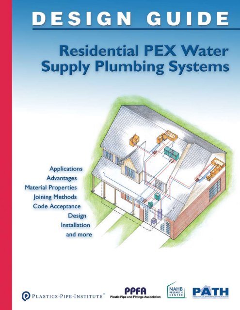
ObjectiveThis <strong>Design</strong> <strong>Guide</strong> provides the information and resources necessary to design and installcross-linked polyethylene (<strong>PEX</strong>) water supply systems in residential buildings. It includescomprehensive design concepts and installation guidelines to increase the acceptance andproper use of <strong>PEX</strong>. This document is targeted to meet the needs of home builders, designers,and trade contractors. Its purpose is to introduce potential users to <strong>PEX</strong> and to enablecurrent users to optimize their <strong>PEX</strong> plumbing and minimize system costs. In addition, it willallow code inspectors and homeowners to become familiar with the applications, performancecharacteristics, and benefits of <strong>PEX</strong> water supply systems.BackgroundCross-linked polyethylene (<strong>PEX</strong>) is a high-temperature, flexible, polymer pipe. Cross-linkingtechnology was first developed in Europe and has since come into use around the world fora variety of applications. <strong>PEX</strong> has a 30-year history of successful use in the European marketwith extensive testing for durability and material performance. It was first introduced in NorthAmerica in 1984 where it has been primarily used for radiant floor heating, and more recently,for domestic water distribution systems. It is approved for potable hot and cold water supplysystems as well as hydronic heating systems in all model plumbing and mechanical codes acrossthe United States and Canada.The comparison of <strong>PEX</strong> to polybutylene piping (PB) appears to be a major obstacle tomainstream acceptance by some code officials, trade contractors, and homeowners. But not allplastics are the same, just as not all metals are the same. Polymer fittings for <strong>PEX</strong> pipe are farmore robust and reliable than those used for PB. A result of modern polymer technology, <strong>PEX</strong>piping performs in ways that provide superior reliability, durability, and safety. Also, currenttesting requirements for <strong>PEX</strong> are much more stringent than when PB piping was accepted andinstalled in housing.1Introduction
Chapter 1 – INTRODUCTIONThe <strong>PEX</strong> piping industry is highly regulated. Standards, specifications, and code requirementsdefine tight material and production quality controls. Continuous-use temperature ratingsas high as 200ºF (93ºC) are required as well as standardized chlorine resistance testing toensure that the piping will withstand the most aggressive drinking water conditions. Nationallyaccredited, third-party certification agencies require strenuous quality control testing, includingrandom plant inspections and annual monitoring testing.There are numerous opportunities for more widespread use of <strong>PEX</strong> pipe in the U.S. residentialmarket. The development of manifolds and parallel plumbing systems for flexible piping hashelped to advance its use. All major residential building codes permit the use of <strong>PEX</strong> piping,but obstacles to its acceptance still remain. There is anecdotal and research information thatshows:• Some plumbers are reluctant to use <strong>PEX</strong> piping due to a lack of experience with installationmethods and design requirements• Some jurisdictions prohibit the use of <strong>PEX</strong> piping for water supply plumbing even though<strong>PEX</strong> pipe is approved for use in all model codes• Codes were originally written for rigid trunk and branch systems; while they have now beenamended to include <strong>PEX</strong> piping systems, they do not provide many system design details• There is a perception among some that <strong>PEX</strong> piping systems are inferior as a buildingproduct, generally based on knowledge of past failures of PB piping systems.Although these hurdles exist, the following are among the many benefits of <strong>PEX</strong> piping systems.• Ease of Installation – <strong>PEX</strong> pipe uses mechanical connections eliminating the need forsolders, flames, and chemicals. Its flexible nature allows it to bend around obstructions. Useof manifolds can speed installation and improve performance.• Corrosion Resistance – <strong>PEX</strong> piping will not pit or stress corrode.• Scaling Resistance – <strong>PEX</strong> pipe’s smooth interior walls and chemical properties make itresistant to mineral build-up.• Cost Effectiveness – <strong>PEX</strong> plumbing systems are less labor intensive and can optimizesystem performance.• Availability of Pipe Sizes – <strong>PEX</strong> piping is available in a wide range of diameters.• Energy Efficiency – <strong>PEX</strong> piping minimizes heat transmission through the pipe wall.• Resistance to Freeze Damage – Under most circumstances, water in the pipe can befrozen and thawed without damaging the pipe.• <strong>Water</strong> Conservation – Well designed <strong>PEX</strong> plumbing systems can reduce the wait time forhot water to reach the fixture.• Environmentally Sound – <strong>PEX</strong> is an inert material and does not contain volatile organiccompounds (VOCs).• Certification – <strong>PEX</strong> pipes and fittings must meet strict performance requirements.
Chapter 1 – INTRODUCTIONAlthough general research on hot water systems has been performed on various aspects ofplumbing systems, a recent literature search by the NAHB Research Center indicated thatspecific system design information for flexible water supply plumbing is sparse. Documentsrelied more on “standard practice” than on engineered or designed systems. Using theseapproaches often leads to system designs that either supply more water than is needed at thefixture, or do not take advantage of the characteristics of a flexible plumbing system to reducecost and improve performance.This <strong>Design</strong> <strong>Guide</strong> provides the information and resources necessary to design and installefficient and cost-effective <strong>PEX</strong> water supply systems in residential buildings. It illustratesvarious plumbing configurations for a variety of house types as well as installation guidelines foreach method. Properly designed and installed <strong>PEX</strong> piping systems are beneficial for plumbingdesigners, installers, and homeowners.Applications<strong>PEX</strong> piping can be used in a wide variety of applications in residential construction. This <strong>Design</strong><strong>Guide</strong> is focused on the design and installation of <strong>PEX</strong> hot and cold water supply systems,which can be used for both new construction and remodeling projects.Other applications for <strong>PEX</strong> are described in a separate section of this guide and include:• Radiant floor heating systems for suspended floor systems or in slab construction• Municipal water service pipe in underground applications• Snow and ice melt systems for sidewalks, driveways, entrances, and ramps• Turf conditioning for greenhouses, golf courses, and sports field surfaces• Fire suppression systems (residential fire sprinklers)Available in sizes from 1/4 to 2 inches, <strong>PEX</strong> piping can generally be installed in place of rigidpiping on a size-for-size basis. Home-run installations with central manifolds can be used tobalance pressures at the outlets and minimize hot water delivery wait time, reducing wastedwater and energy. Manifolds can be installed that reduce the amount of piping and fittings,speed-up installation, and balance pressures throughout the system.How to Use the <strong>Design</strong> <strong>Guide</strong>This <strong>PEX</strong> <strong>Design</strong> <strong>Guide</strong> can be used by anyone considering the installation of <strong>PEX</strong> pipingfor a residential plumbing system. It can be used by the novice as an introduction to <strong>PEX</strong>piping or by the experienced plumber to optimize his/her approach. Building code officialscan use this <strong>Guide</strong> as a consolidated source of information on the application of <strong>PEX</strong> pipingin residential buildings. Builders can use this guide to learn about the advantages, installationissues, and expected performance of <strong>PEX</strong> plumbing systems for discussions with sales staff andhomeowners.
Chapter 1 – INTRODUCTIONEach section of this guide focuses on various aspects of using <strong>PEX</strong> piping.• Chapter 1 – Introduction: Background information to educate the user about the historyand uses of <strong>PEX</strong> piping• Chapter 2 – Advantages: Various advantages to using <strong>PEX</strong> piping in residential buildings• Chapter 3 – Material Properties: Unique properties of <strong>PEX</strong> piping• Chapter 4 – Joining Methods: Explanations of the various types of fittings and theirjoining methods• Chapter 5 – Types of <strong>PEX</strong> <strong>Plumbing</strong> <strong>Systems</strong>: Descriptions of the three types of <strong>PEX</strong>piping system designs• Chapter 6 – Code Acceptance: Information on major plumbing codes and relevantjurisdictional code provisions for <strong>PEX</strong> piping• Chapter 7 – <strong>Design</strong>: <strong>Design</strong>s and performance details of the three basic plumbing layoutsfor four common house configurations to assist in evaluating which system provides the bestbalance of performance, ease of installation, and cost for a particular house• Chapter 8 – Lab Testing and Performance Data: System performance comparison ofthree plumbing systems• Chapter 9 – Installation: Detailed instructions for installing <strong>PEX</strong> piping• Chapter 10 – Testimonials: Quotes from plumbers and home builders on theirexperiences with <strong>PEX</strong> piping• Chapter 11 – Other Applications: Other uses of <strong>PEX</strong> piping• Appendix A: Additional lab testing data• Appendix B: New Installation Checklist to aid plumbers with the process of installing <strong>PEX</strong>piping• Appendix C: Resources for additional information beyond this <strong>Design</strong> <strong>Guide</strong>• Glossary: List of terms and acronyms used in this <strong>Design</strong> <strong>Guide</strong>There are three main ways to use this guide:• Introductory Overview: The guide can be read in its entirety as an introduction for thosewho have little or no exposure to <strong>PEX</strong> piping.• Planning Tool: The Code Acceptance and <strong>Design</strong> chapters, in particular, can be used tooptimize system designs and building layouts during the planning stage while the home designis being finalized.• Reference <strong>Guide</strong>: Certain sections can be extracted and read as needed. For example,plumbers may want to reference the Installation section, or building inspectors may want toreference the Code Acceptance section.
Ease of InstallationThe installation of <strong>PEX</strong> pipe is generally easier than rigid pipe. It is available in long coils whicheliminates the need for coupling joints. Its flexible nature allows it to be bent gently aroundobstructions, minimizing the use of fittings. No solvent, chemical, or solder joining is required.The mechanical fittings are secure and reliable when installed properly. The pipe is lightweight,making it safe to transport and easy to handle. For a comparison of the installation of rigidmetal pipe to <strong>PEX</strong> pipe, refer to the PATH Field Evaluation in Lincoln, Neb. 1DurabilityBased on extensive testing and material performance over the span of more than 30 years,<strong>PEX</strong> piping has proven to be a durable material that does not suffer from some of the historicalproblems associated with metallic piping, such as reduced interior dimension, corrosion,electrolysis, filming, mineral build-up, and water velocity wear. <strong>PEX</strong> piping will typically expandif the system is allowed to freeze, and return to its original size when the water thaws.Cost Effectiveness<strong>PEX</strong> plumbing systems have lower installation costs than rigid metallic plumbing systems.Installation time and labor required is greatly reduced. In service, the use of <strong>PEX</strong> systems canreduce energy and water use by delivering water to the fixtures faster and by reducing losses inthe piping.Energy Efficiency<strong>PEX</strong> piping offers reduced heat loss and improved thermal characteristics when compared tometallic pipe. In addition, less energy is used by the water heater because of shorter deliverytime for hot water with <strong>PEX</strong> parallel plumbing systems. 22ADVANTAGES1The full PATH Field Evaluation report is available at http://www.toolbase.org.2Evaluation of Hot <strong>Water</strong> Distribution <strong>Systems</strong> by Numeric Simulation, 2004.Building Technology Center, Oak Ridge National Laboratory.
Chapter 2 – ADVANTAGESNoise ReductionWhen properly secured, <strong>PEX</strong> piping can be significantly quieter than rigid systems. It isinherently less noisy due to its flexibility and ability to absorb pressure surges.<strong>Water</strong> ConservationProperly designed <strong>PEX</strong> plumbing systems have the potential to conserve water (see Chapters 5and 7). The flexibility of <strong>PEX</strong> allows it to bend around corners and run continuously, reducingthe need for fittings; this allows downsizing the pipe diameter to 3/8-inch for certain fixtures.Home-run systems and 3/8-inch pipes minimize the time it takes hot water to reach thefixture. Lengthy delivery time for hot water represents a significant waste of water as well asenergy; a problem exacerbated in larger homes.In 2002, the NAHB Research Center conducted software simulations and laboratory tests ona “typical” hot water system using a trunk and branch rigid pipe design and one that included a3/8-inch diameter <strong>PEX</strong> home-run system. Results indicated that systems using shorter 3/8-inchruns with a home-run manifold reduced the wait time for hot water and wasted less water thanlonger runs of rigid pipe with many elbows and connections. 3Environmentally Sound<strong>PEX</strong> is a modification or enhancement of high-density polyethylene, an economical and highlycost-effective construction piping material. Generally, manufacturing equivalent lengths ofplastic pipe consumes far less energy than manufacturing metallic pipe. The lighter weight of<strong>PEX</strong> compared to metallic piping helps to lower transportation costs and energy consumption,offering even greater benefit.<strong>PEX</strong> pipes can be recycled as an inert filler material that can be incorporated into otherpolymers for specific applications. There is also reduced water use through faster delivery time.In addition, <strong>PEX</strong> pipe does not contain harmful VOCs.3Performance Comparison of <strong>Residential</strong> Hot <strong>Water</strong> <strong>Systems</strong>,November 2002, NAHB Research Center report available athttp://www.toolbase.org/.
3MATERIALPROPERTIES<strong>PEX</strong> is a material made up of molecules of high-density polyethylene (HDPE) that arepermanently linked to each other by a process called crosslinking. Crosslinking makes <strong>PEX</strong> a“thermoset” polymer, which gives it long-term stability.Polyethylene can be crosslinked using several technologies. All methods induce links betweenthe single strands of PE to form a dense network through radical reactions. The numberof links between the strands determines the crosslink density and is an important factor indetermining the physical properties of the material. The minimum percent crosslinking foreach method is specified in the ASTM F 876 standard. The three most common methods ofcrosslinking polyethylene are as follows:Peroxide – Peroxides are heat-activated chemicals that generate free radicals forcrosslinking. This is called the Engel Process.Moisture-cured Vinylsilane – This method involves grafting a reactive silanemolecule to the backbone of the polyethylene. This is called the Silane Process.Beta Irradiation – This method involves subjecting a dose of high-energy electronsto the PE. This is called the Radiation Process.In European standards these three methods are referred to as <strong>PEX</strong>-A, <strong>PEX</strong>-B, and <strong>PEX</strong>-C,respectively, and are not related to any type of rating system.<strong>PEX</strong> pipe produced by any of the three methods must meet the same qualification requirementsas specified in the <strong>PEX</strong> standards. Although methods of crosslinking produce differentcharacteristics, all three methods have been utilized to manufacture approved <strong>PEX</strong> products.As required in any manufacturing process, procedures for each technology must be establishedand followed with good quality control checks in place to produce quality products.
Chapter 3 – MATERIAL PROPERTIESTemperature and Pressure<strong>PEX</strong> piping meets all requirements for pressure and temperature performance in residentialapplications. Consensus standards published by the American Society for Testing and Materials(ASTM) International specify temperature and pressure-resistant capabilities of <strong>PEX</strong> pipe andall tubing used in residential applications bears the appropriate test marking.In the event of a water heating system malfunction, <strong>PEX</strong> piping is designed to accommodateshort-term conditions of 48 hours at 210ºF (99ºC) and 150 psi (1034 kPa) until repairs canbe made. The most commonly used safety relief valve (T&P) activates (opens) at either ofthese temperature or pressure conditions. All <strong>PEX</strong> piping has been tested to withstand T&Pactivation for 30 days to ensure that safety requirements are met. As such, <strong>PEX</strong> systems DONOT require the use of a special T&P valve.ASTM F 876: Standard Specification for Cross-Linked Polyethylene (<strong>PEX</strong>) Tubing covers<strong>PEX</strong> piping that is outside diameter controlled, and pressure rated for water at threetemperatures—160 psi @ 73.4ºF, 100 psi @ 180ºF, and 80 psi @ 200ºF. Included arerequirements and test methods for material, workmanship, dimensions, hydrostatic sustainedpressure strength, burst pressure, oxidative (chlorine) resistance, and environmental stresscracking.ASTM F 877: Standard Specification for Cross-Linked Polyethylene (<strong>PEX</strong>) Plastic Hot- and Cold-<strong>Water</strong> Distribution <strong>Systems</strong> covers requirements and test methods for <strong>PEX</strong> hot- and cold-waterdistribution system components made in one standard dimension ratio, and intended for 100psi water service, up to and including a maximum working temperature of 180ºF. Componentsare comprised of piping and fittings. Requirements and test methods are included forhydrostatic sustained pressure strength, thermocycling resistance, fittings, and bend strength.FlexibilityThe flexible nature of <strong>PEX</strong> allows it to be bent gently around obstructions and installed as onecontinuous run without fittings. Slight changes in direction are made easily by bending the pipeby hand. There is a predetermined bend radius of a 90-degree change of direction withoutinstalling a fitting (reference manufacturer’s installation instructions). Minimizing mechanicalconnections can result in quicker installations, less potential for leaks at fittings, and lessresistance due to pressure drops through fittings.Noise and <strong>Water</strong> Hammer ResistanceAs water flows through pipes, pressure in the system gives moving water energy, known askinetic energy. Kinetic energy increases with the speed of water and also with the mass ofwater that is flowing. When the flow of water is stopped, such as when a valve or faucet isclosed, this kinetic energy must be dissipated in the system.The ability of a plumbing pipe to dissipate energy due to surge in water pressure is basedon the pipe’s modulus of elasticity, a measure of material stiffness. A higher modulus ofelasticity means the material is more rigid. Copper pipe is 180 times more rigid than <strong>PEX</strong> pipe.Ultimately, this means that with rigid piping systems, pressure surges can produce noticeablebanging sounds as energy is dissipated, thus causing what is known as “water hammer.” Thepressure surge that causes water hammer can produce instantaneous pressures of 300 to 400psi (2070 to 2760 kPa), which can cause damage to rigid pipes, fittings, and connections.
Chapter 3 – MATERIAL PROPERTIESThe flexibility of <strong>PEX</strong> pipe allows the pipe itself to absorb energy from pressure surges andeliminate or reduce the occurrence of water hammer.Resistance to Freeze Damage<strong>PEX</strong> pipes are less susceptible to the effects of cold temperatures retaining their flexibility evenbelow freezing. This flexibility means that if water-filled <strong>PEX</strong> piping freezes, the elasticity of thematerial allows it to expand without cracking or splitting, and then to return to its original sizeupon thawing. This applies when <strong>PEX</strong> pipes have room to expand evenly along their length, as istypical when installed within walls or ceilings. <strong>PEX</strong> pipes inside a slab may not be able to expandevenly.Chlorine ResistanceThe U.S. Environmental Protection Agency (EPA) recommends that all drinking water bedisinfected, typically using free chlorine, chloramines, or other less common methods.Currently, the majority of potable drinking water in the United States and Canada is disinfectedusing free chlorine. For water treated with free chlorine, the EPA sets a maximum disinfectantlevel of 4.0 parts per million (ppm) within the water distribution system.The second-most common disinfectant is chloramines. Research conducted by JanaLaboratories, at the request of the Plastics Pipe Institute (PPI), indicates that free chlorine isgenerally more aggressive to cross-linked polyethylene (<strong>PEX</strong>) pipes than chloramines.To ensure the reliability of <strong>PEX</strong> piping systems in hot chlorinated water applications, it is arequirement of the <strong>PEX</strong> pipe product standard specification ASTM F 876 that all <strong>PEX</strong> pipesintended for use with potable water have a minimum extrapolated lifetime of 50 years whentested in accordance with test method ASTM F 2023: “Standard Test Method for Evaluating theOxidative Resistance of Cross-linked Polyethylene (<strong>PEX</strong>) Tubing and <strong>Systems</strong> to Hot Chlorinated<strong>Water</strong>.” The minimum requirement applies to traditional domestic applications. 4The test conditions of ASTM F 2023 require that the test fluid has a minimum oxidativereduction potential (ORP) of 825 mV. To produce test fluid with this high ORP, third-party testlaboratories typically use reverse osmosis-purified water with a free chlorine concentrationof 4.3 +/- 0.3 ppm (4.3 mg/L) and pH of 6.8 +/- 0.2, resulting in an ORP of 825 mV or higher.This represents a very aggressive water quality, which gives conservative results. This testprocedure is designed to extrapolate the life expectancy of a hot-water plumbing pipe whenused at a water temperature of 140°F and a pressure of 80 psi. Continuous recirculation andtraditional domestic 4 conditions can both be evaluated by ASTM F 2023.<strong>PEX</strong> pipe manufacturers must have pipes tested and certified by NSF International, UL and/orother third-party certification agencies to meet the requirements of ASTM F 876, includingchlorine resistance. In addition, manufacturers may have pipes certified to NSF Internationalprotocol P 171: “Chlorine Resistance of Plastic Piping Materials.” <strong>PEX</strong> piping systems use fittingsthat also must comply with ASTM standards, and are made from brass, copper, or hightemperatureengineered polymers that are chlorine-resistant.In summary, <strong>PEX</strong> pipe has shown itself to be resistant to attack from chlorine and chloraminesunder a wide range of conditions, and has performed reliably in all regions of North America.4Traditional domestic applications are defined in ASTM F 2023 as piping systems which operate for upto 25 percent of the service time at a water temperature of 140°F (60°C) and 75 percent of the timeat ambient room temperatures. A plumbing system with more demanding water quality conditionsthan those listed above should be discussed with the <strong>PEX</strong> piping manufacturer before installation.
Chapter 3 – MATErIAL ProPErTIESCorrosion Resistance<strong>PEX</strong> pipe and fi ttings have been tested extensively with aggressive potable water conditions anddid not pit or corrode. <strong>PEX</strong> pipe and fi ttings are tested with corrosive pH levels between 6.5and 6.7, much lower and more aggressive than levels found in common water systems.A related aspect of corrosion in pipes is concerned with fl ow erosion. Flow erosion tests of<strong>PEX</strong> fi ttings were conducted by the PPI High Temperature Division (HTD). See “Erosion Studyon Brass Insert Fittings Used in <strong>PEX</strong> Piping <strong>Systems</strong>,” PPI-TN-26 for discussion and results.Ultraviolet (UV) ResistanceLike most plastics, the long-term performance of <strong>PEX</strong> will be affected by UV radiation fromsunlight. Although most <strong>PEX</strong> pipes have some UV resistance, <strong>PEX</strong> pipes should not be storedoutdoors where they are exposed to the sun. Precautions must be taken once the pipe isremoved from the original container. Each <strong>PEX</strong> pipe manufacturer publishes a maximumrecommended UV exposure limit, based on the UV resistance of that pipe. Do not allow <strong>PEX</strong>pipes to be over-exposed beyond these limits. <strong>PEX</strong> pipes should not be installed outdoors,unless they are buried in earth or properly protected from UV exposure, either direct orindirect.Indirect (diffused) and refl ected sunlight also have UV energy. If <strong>PEX</strong> will be exposed tosunlight continuously after installation, such as in an unfi nished basement, cover the pipe witha UV-blocking sleeve (black preferred) or approved pipe insulation. Different manufacturers’pipes have different degrees of UV resistance as indicated on their labels; always follow therecommendations provided by the particular manufacturer.See PPI “UV Labeling <strong>Guide</strong>lines for <strong>PEX</strong> Pipes,” TN-32.Caution• Do not store <strong>PEX</strong> pipes outdoors.• Keep <strong>PEX</strong> pipes in original packaginguntil time of installation.• Ensure that exposure to sunlightduring installation does not exceedthe maximum recommended UVexposure time as recommended bythe manufacturer.10
Chapter 3 – MATERIAL PROPERTIESInert Material – Safe for Drinking <strong>Water</strong>Since <strong>PEX</strong> piping is used to transport potable water, it must comply with federal regulationsfor public safety. <strong>PEX</strong> materials are inert (not chemically reactive) and cannot contaminate thepotable water passing through them. The fittings are mechanical and do not require the use ofsolvents or chemicals that might leach into the water when the system is first used.Testing and certification must comply with NSF/ANSI Standard 61: Drinking <strong>Water</strong> SystemComponents - Health Effects, and Standard 14: Plastic Pipe System Components and RelatedMaterials. The primary focus of Standard 61 is to establish minimum health effect requirementsfor chemical contaminants and impurities that are indirectly imparted into drinking waterfrom products, components, and materials used in potable water systems. <strong>PEX</strong> piping systemsare tested at water pH levels from 5.0 to 10.0, both excessive acidity and alkalinity, beyondlevels encountered in potable water systems. <strong>PEX</strong> pipe does not corrode, and it is resistantto mineral build-up. NSF/ANSI Standard 14 covers physical, performance, and health effectrequirements for plastic piping system components used in potable hot- and cold-waterdistribution systems.<strong>PEX</strong> Piping Dimensions and Flow CharacteristicsNominalDiameterTable 3.1 – <strong>PEX</strong> Pipe DimensionsOD Wall ID Weightinches 1 inches 2 inches lb/ft3/8” 0.500 0.075 0.350 0.051/2” 0.625 0.075 0.475 0.063/4” 0.875 0.102 0.671 0.101” 1.125 0.130 0.865 0.161 1/4” 1.375 0.160 1.055 0.251 1/2” 1.625 0.190 1.245 0.352” 2.125 0.248 1.629 0.601Average OD from ASTM F 8762Average wall thickness from ASTM F 87611
Chapter 3 – MATERIAL PROPERTIESTable 3.2 – Flow VelocityFlow Rateft/secGPM 3/8” 1/2” 5/8” 3/4” 1” 1 1/4” 1 1/2” 2”0.2 0.67 0.36 0.25 0.18 0.11 0.07 0.05 0.030.3 1.00 0.54 0.37 0.27 0.16 0.11 0.08 0.050.4 1.33 0.72 0.50 0.36 0.22 0.15 0.11 0.060.5 1.67 0.91 0.62 0.45 0.27 0.18 0.13 0.080.6 2.00 1.09 0.74 0.54 0.33 0.22 0.16 0.090.7 2.33 1.27 0.87 0.64 0.38 0.26 0.18 0.110.8 2.67 1.45 0.99 0.73 0.44 0.29 0.21 0.120.9 3.00 1.63 1.12 0.82 0.49 0.33 0.24 0.141.0 3.33 1.81 1.24 0.91 0.55 0.37 0.26 0.151.1 3.67 1.99 1.36 1.00 0.60 0.40 0.29 0.171.2 4.00 2.17 1.49 1.09 0.66 0.44 0.32 0.181.3 4.34 2.35 1.61 1.18 0.71 0.48 0.34 0.201.4 4.67 2.53 1.74 1.27 0.76 0.51 0.37 0.221.5 5.00 2.72 1.86 1.36 0.82 0.55 0.40 0.231.6 5.34 2.90 1.98 1.45 0.87 0.59 0.42 0.251.7 5.67 3.08 2.11 1.54 0.93 0.62 0.45 0.261.8 6.00 3.26 2.23 1.63 0.98 0.66 0.47 0.281.9 6.34 3.44 2.36 1.72 1.04 0.70 0.50 0.292.0 6.67 3.62 2.48 1.81 1.09 0.73 0.53 0.312.5 8.34 4.53 3.10 2.27 1.36 0.92 0.66 0.383.0 10.00 5.43 3.72 2.72 1.64 1.10 0.79 0.463.5 11.67 6.34 4.34 3.18 1.91 1.28 0.92 0.544.0 7.24 4.96 3.63 2.18 1.47 1.05 0.624.5 8.15 5.58 4.08 2.46 1.65 1.19 0.695.0 9.05 6.20 4.54 2.73 1.84 1.32 0.776.0 10.86 7.44 5.44 3.28 2.20 1.58 0.927.0 8.68 6.35 3.82 2.57 1.84 1.088.0 9.92 7.26 4.37 2.94 2.11 1.239.0 11.16 8.17 4.91 3.30 2.37 1.3912
Chapter 3 – MATERIAL PROPERTIESTable 3.2 – Flow Velocity (continued)Flow Rateft/secGPM 3/8” 1/2” 5/8” 3/4” 1” 1 1/4” 1 1/2” 2”10.0 9.07 5.46 3.67 2.64 1.5411.0 9.98 6.01 4.04 2.90 1.6912.0 10.89 6.55 4.40 3.16 1.8513.0 7.10 4.77 3.43 2.0014.0 7.64 5.14 3.69 2.1615.0 8.19 5.51 3.95 2.31Table 3.3 – Pressure Loss60°F (16°C) <strong>Water</strong>Flow RatePressure Loss psi/100 ft of PipeGPM 3/8” 1/2” 5/8” 3/4” 1” 1 1/4” 1 1/2” 2”0.2 0.427 0.099 0.040 0.019 0.006 0.002 0.001 0.00030.3 0.880 0.204 0.083 0.039 0.012 0.005 0.002 0.0010.4 1.470 0.341 0.138 0.065 0.019 0.008 0.003 0.0010.5 2.189 0.508 0.205 0.097 0.029 0.011 0.005 0.0010.6 3.032 0.703 0.284 0.135 0.040 0.015 0.007 0.0020.7 3.993 0.926 0.374 0.177 0.053 0.020 0.009 0.0030.8 5.069 1.175 0.475 0.225 0.067 0.026 0.012 0.0030.9 6.258 1.450 0.586 0.278 0.082 0.032 0.014 0.0041.0 7.555 1.751 0.707 0.335 0.099 0.038 0.017 0.0051.1 8.960 2.076 0.839 0.397 0.118 0.046 0.021 0.0061.2 10.47 2.425 0.980 0.464 0.138 0.053 0.024 0.0071.3 12.08 2.799 1.131 0.535 0.159 0.061 0.028 0.0081.4 13.80 3.195 1.291 0.611 0.181 0.070 0.032 0.0091.5 15.61 3.615 1.460 0.691 0.205 0.079 0.036 0.0101.6 17.52 4.058 1.639 0.776 0.230 0.089 0.040 0.0111.7 19.53 4.523 1.827 0.865 0.256 0.099 0.045 0.0121.8 21.64 5.010 2.023 0.958 0.284 0.110 0.050 0.01413
Chapter 3 – MATERIAL PROPERTIESTable 3.3 – Pressure Loss (continued)60°F (16°C) <strong>Water</strong>Flow RatePressure Loss psi/100 ft of PipeGPM 3/8” 1/2” 5/8” 3/4” 1” 1 1/4” 1 1/2” 2”1.9 23.84 5.519 2.229 1.055 0.313 0.121 0.055 0.0152.0 26.14 6.050 2.443 1.157 0.343 0.133 0.060 0.0172.5 39.00 9.024 3.643 1.724 0.511 0.197 0.089 0.0253.0 54.10 12.51 5.050 2.390 0.708 0.274 0.124 0.0343.5 71.36 16.50 6.658 3.150 0.933 0.360 0.163 0.0454.0 20.97 8.459 4.002 1.185 0.458 0.207 0.0574.5 25.90 10.45 4.943 1.463 0.565 0.256 0.0715.0 31.30 12.63 5.972 1.768 0.683 0.309 0.0856.0 43.44 17.52 8.284 2.451 0.946 0.428 0.1187.0 23.11 10.93 3.232 1.248 0.564 0.1568.0 29.38 13.89 4.108 1.585 0.717 0.1989.0 36.32 17.17 5.076 1.959 0.885 0.24410.0 20.75 6.134 2.367 1.070 0.29511.0 24.63 7.281 2.808 1.269 0.35012.0 28.81 8.514 3.284 1.484 0.40913.0 9.832 3.792 1.713 0.47214.0 11.24 4.332 1.957 0.53915.0 12.72 4.905 2.216 0.610Shown is pressure loss in units of psi per 100 feet of pipe.14
4CodEACCEPTAnCE<strong>PEX</strong> plumbing systems are recognized in all major building model codes and are commonly usedfor hot- and cold-water distribution applications, water service lines, and radiant fl oor heatingsystems. The following is a summary of relevant model code requirements which specifi callypertain to <strong>PEX</strong> and plastic pipe and fi ttings used for domestic water supply.The user must determine which codes areapplicable to his/her specifi c project, and alsomust ensure compliance with all local, state,and federal codes, regulations, and standards.Codes are constantly reviewed and updated.<strong>PEX</strong> water supply piping has been adopted inthe model codes since 1993.International <strong>Residential</strong> Code (IRC-2003)P2605 Support, P2605.1 General. Piping shall be supported at distances not to exceedthose indicated in Table 2605.1. For <strong>PEX</strong>, maximum horizontal support spacing is 32 inches, andmaximum vertical support spacing is 10 feet (mid-story guide for sizes 2 inches and smaller).P2608.3 Plastic Pipe, Fittings, and Components. All plastic pipe, fi ttings, andcomponents shall be third-party certifi ed as conforming to NSF 14.P2903.8 Parallel <strong>Water</strong>-Distribution System Manifolds. Hot and cold parallel waterdistributionsystem manifolds with individual distribution lines to each fi xture or fi xture fi ttingshall be sized and installed in accordance with Sections P2903.8.1 through P2903.8.7.15
Chapter 4 – CODE ACCEPTANCEP2903.8.1 Sizing of Manifolds. Manifolds shall be sized in accordance with Table P2903.8.1.A maximum gallon per minute (gpm) is specified for different nominal inside diameter sizes forplastic and metallic manifolds.P2903.8.3 Maximum Length. The maximum length of individual distribution lines shall be60 feet (18.2 m) nominal.P2903.8.5 Support and Protection. Plastic piping bundles shall be secured in accordancewith manufacturer’s installation instructions and supported in accordance Section P2605.Bundles that have a change in direction equal to or greater than 45 degrees shall be protectedfrom chaffing at the point of contact with framing members by sleeving or wrapping.P2904.5 <strong>Water</strong> Distribution Pipe. References Table P2904.5. <strong>PEX</strong> plastic tubing shallconform to ASTM F 877 and CSA B137.5 standards.P2904.9.1.4 Cross-linked Polyethylene Plastic (<strong>PEX</strong>). References Section P2904.9.1.4.1or Section P2904.1.4.2.P2904.9.1.4.2 Mechanical Joints. Mechanical joints shall be installed in accordance withmanufacturer’s instructions. Fittings for <strong>PEX</strong> plastic tubing as described in ASTM F 1807, ASTMF 1960, ASTM F 2080, and ASTM F 2159, shall be installed in accordance with manufacturer’sinstructions.P2904.16.2 Plastic Pipe or Tubing to Other Pipe Materials. Joints between differentgrades of plastic pipe or between plastic pipe and other piping material shall be made with anapproved adapter fitting.International <strong>Plumbing</strong> Code (IPC 2003)605.3 <strong>Water</strong> Service Pipe. <strong>Water</strong> service pipe shall conform to NSF61 and shall conform toone of the standards listed in Table 605.3 (ASTM F 876, ATM F 877, and CSA-B137.5).605.4 <strong>Water</strong> Distribution Pipe. <strong>Water</strong> distribution pipe shall conform to NSF 61 and shallconform to one of the standards listed in Table 605.4 (ASTM F 877, and CSA-B137.5).605.5 Fittings. Pipe fittings shall be approved for installation with the piping material installedand shall conform to one of the standards listed in Table 605.5 (ASTM F 1807, ASTM F 1960,and ASTM F 2080).605.17 Cross-linked Polyethylene Plastic. Joints between cross-linked polyethylene plastictubing or fittings shall comply with Sections 605.17.1 and 605.17.2.605.17.3 Mechanical Joints. Mechanical joints shall be installed in accordance withmanufacturer’s instructions. Fittings for <strong>PEX</strong> tubing as described in ASTM F 1807, ASTM F1960, and ASTM F 2080 shall be installed in accordance with manufacturer’s instructions605.23.2 Plastic Pipe or Tubing to Other Piping Material. Joints between differentgrades of plastic pipe or between plastic pipe and other piping material shall be made with anapproved adapter fitting.16
Chapter 4 – CODE ACCEPTANCENational Standard <strong>Plumbing</strong> Code (NSPC 2003)3.4.1. Plastic Piping. Plastic piping materials used for the conveyance of potable water shallcomply with NSF 14 and be marked accordingly.3.4.2. <strong>Water</strong> Service Piping. <strong>Water</strong> service piping to the point of entrance into the buildingshall be of materials listed in Table 3.4, and shall be water pressure rated for not less than 160psig at 73°F. Table 3.4: <strong>PEX</strong> Plastic <strong>Water</strong> Distribution <strong>Systems</strong> (ASTM F 877 with ASTM F1807, F 1960, or F 2098 Fittings)3.4.3. <strong>Water</strong> Distribution Piping. <strong>Water</strong> piping for distribution of hot and cold waterwithin buildings shall be of materials listed in Table 3.4, and shall be water pressure rated fornot less than 100 psig at 180°F. Plastic piping used for hot water distribution shall be installed inaccordance with requirements of Section 10.15.8. NOTE: The working pressure rating for certainapproved plastic piping materials varies depending on pipe size, pipe schedule, and methods ofjoining.10.15.8 Plastic Piping. Plastic piping used for hot-water distribution shall conform to therequirements of Section 3.4 and Table 3.4. Piping shall be water pressure rated for not lessthan 100 psi at 180°F. NOTE: The working pressure rating for certain approved plastic pipingmaterials varies depending on pipe size, pipe schedule, and methods of joining. Plastic pipeor tube shall not be used downstream from instantaneous water heaters, immersion waterheaters or other heaters not having approved temperature safety devices. Piping within 6inches of flue or vent connectors shall be approved metallic pipe or tube. Normal operatingpressure in water distribution piping systems utilizing approved plastic pipe or tube for hotwaterdistribution shall not be more than 80 psi.Uniform <strong>Plumbing</strong> Code (UPC-2003)604.11 <strong>PEX</strong>. Cross-linked polyethylene (<strong>PEX</strong>) tubing shall be marked with the appropriatestandard designation(s) (see Chapter 9) for which the tubing has been approved. <strong>PEX</strong> tubingshall be installed in compliance with the provisions of this section.604.11.1 <strong>PEX</strong> Fittings. Metal insert fittings, metal compression fittings, and cold expansionfittings used with <strong>PEX</strong> tubing shall be manufactured to and marked in accordance with thestandards for the fittings (see Chapter 9).604.11.2 <strong>Water</strong> Heater Connections. <strong>PEX</strong> shall not be installed within the first 18 inches(457 mm) of piping connected to a water heater.International Code Council (ICC)Evaluation Service Reports (ESR) and Evaluation Reports (ER)International Code Council-Evaluation Service (ICC-ES) conducts technical evaluations ofbuilding products, components, methods, and materials. The evaluation process culminateswith issuance of technical reports that, because they directly address code compliance, areuseful to both regulatory agencies and building-product manufacturers. Agencies use evaluationreports to determine code compliance and enforce building regulations; manufacturers use17
Chapter 4 – CODE ACCEPTANCEreports as evidence that their products meet code requirements and warrant regulatoryapproval. Several <strong>PEX</strong> manufacturers have ESRs or ERs. Evaluation Reports can be obtainedfrom www.icc-es.org.International Association of <strong>Plumbing</strong> and Mechanical Officials(IAPMO) <strong>Guide</strong> CriteriaThe IAPMO <strong>Guide</strong> Criteria (IGC) procedure provides manufacturers and product developersan opportunity to draft IAPMO standards as a vehicle for introducing new products, whenno applicable standard exists for the product. Once an IGC is accepted, IAPMO can listproducts manufactured in compliance with the new requirements. Some <strong>PEX</strong> and <strong>PEX</strong> fittingmanufacturers have products listed under IGCs. Lists of IGCs can be obtained fromwww.iapmo.org.C904-06 American <strong>Water</strong>works Association (ANSI/AWWAC904-06)This standard describes <strong>PEX</strong> pressure pipe made from material having a standard <strong>PEX</strong> materialdesignation code of <strong>PEX</strong> 1006 in ASTM F 876 for use as underground water service lines insizes 1/2 inch through 3 inches, and conform to a standard dimension ration of SDR9.Included in this standard are criteria for classifying <strong>PEX</strong> plastic pipe materials and a system ofnomenclature, requirements, and test methods for materials and pipe. Methods of marking aregiven. <strong>Design</strong>, installation, and application considerations are discussed in the forward of thisstandard.18
There are several types of joining methods or fi ttings used with <strong>PEX</strong> plumbing systems. All aremechanical fi ttings that are either directional or transitional. <strong>PEX</strong> piping cannot be joined bysolvent cementing.Most <strong>PEX</strong> piping manufacturers have their own mechanicalfi tting system. The method of connection should complywith the manufacturer’s recommendations and instructions.Fittings are regulated to comply with performance andmaterial criteria from recognized standards. They shouldbe marked by a certifi ed third-party agency such as NSF,IAPMO, CSA, IGC, UL or other third-party testing and listingagency.The most common types of fi tting systems used are Cold Expansion Fittings and Metal orPlastic Insert Fittings. Other types of fi ttings are available but are less common.5JoInInGMETHodSNot all fi ttings are applicablewith all <strong>PEX</strong> pipe. Consult yourmanufacturer for acceptablemethods.19
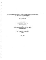
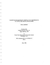
Chapter 5 – JOINING METHODSCold Expansion Fittings with <strong>PEX</strong> Reinforced RingsThis type of fitting requires that the <strong>PEX</strong> piping, with a reinforcing <strong>PEX</strong> ring placed over theend of the pipe, is expanded before the fitting is inserted into the pipe end. The expanded pipeend is allowed to retract onto the fitting to form the seal—the “memory” of the pipe allows itto tighten over the fitting. An expander tool is required to expand the pipe and the <strong>PEX</strong> ringtogether. ASTM F 1960 is applicable to fittings that use a <strong>PEX</strong> reinforcing ring.Figure 5.1 – Cold Expansion Polymer Fitting with <strong>PEX</strong>Reinforced RingFigure 5.2 – Cold Expansion Metal Fitting with <strong>PEX</strong>Reinforced RingCold Expansion Fittings with Metal Compression SleevesThis type of fitting requires that the <strong>PEX</strong> piping is expanded before it is placed over theoversized fitting. The pipe shrinks down over the fitting insert, then a metal compressionsleeve is pulled over the connection, compressing the pipe over the fitting. A tool is requiredto expand the pipe and to pull the sleeve overthe pipe. ASTM F 2080 is applicable to coldexpansion fittings that use a metal compressionsleeve.Figure 5.3 – Cold Expansion Fitting with MetalCompression Sleeve20
Chapter 5 – JOINING METHODSMetal or Plastic Insert FittingsThis type of fitting uses a metal crimp ring that is compressed around the <strong>PEX</strong> piping to secureit to the fitting. The crimp ring can be copper or stainless steel. Fittings can be made of copper,brass, bronze, or plastic. The fitting will typically have a barbed or ribbed annular end.The <strong>PEX</strong> pipe slides over the barbed or ribbed annular section. Prior to making the connection,the metal crimp ring is slid over the <strong>PEX</strong> piping and away from the end of the pipe. The piping ispushed over the fitting, the crimp ring is slid down over that section and aligned over the fittingribs, and a tool is used to compress the crimp ring around the assembly.Copper Crimp RingThe copper ring is crimped equally around the fitting. The go-no-go gauge ensures a propercrimp. Some manufacturers use o-rings on their metal fittings to make the seal with the pipe.ASTM F 1807 is the applicable standard for metal insert fittings. ASTM F 2159 is the applicablestandard for plastic fittings. ASTM 2434is the applicable standard for metal insertfittings with o-rings.Figure 5.4 – Metal Insert Fitting with Copper CrimpRingFigure 5.5 – Plastic Insert Fitting with Copper CrimpRingFigure 5.6 – Metal Insert Fitting with O-rings andCopper Crimp Ring21
Chapter 5 – JOINING METHODSStainless Steel ClampThe stainless steel ring is crimped using a ratcheting tool, which only releases once a propercrimp is achieved. ASTM 2098 is the applicable standard for stainless steel insert rings.Figure 5.7 – Metal Insert Fitting with Stainless SteelClamp BandFigure 5.8 – Metal Insert Fitting with Stainless SteelClamp SleeveStainless Steel SleeveThis type of fitting is made of metal and uses a press sleeve or cap to secure the <strong>PEX</strong> pipe tothe fitting. These fittings have ribbed annular ends that are inserted into the <strong>PEX</strong> pipe. A sleeveor cap slides over the outer part of the piping and the fitting is inserted into the pipe. The pipemust be fully inserted. A press tool is used to make the final connection. It is important thatthe appropriate tool is used per manufacturer’sinstructions. This type of fitting is often used inother industries to make pneumatic or hydraulichose line connections.Figure 5.9 – Metal Insert Fitting with Stainless SteelPress Sleeve22
Chapter 5 – JOINING METHODSPush Type FittingsThis type of fitting uses an interlocking mechanism to connect the <strong>PEX</strong> pipe to the fitting.The pipe is inserted, or pushed, into the fitting, and locked into place with a fastening devicethat keeps the pipe from being backed-out or disconnected. This type of fitting is sometimesreferred to as a “quick connect” fitting. Push type fittings typically use some type of o-ringor gasket to form a seal around the <strong>PEX</strong>pipe. A support liner is inserted intothe pipe, and a fastening system with alocking component, such as a snap ringor twist collar, is used to ensure thatthe connection remains permanent.ASSE 1061 and IAPMO – IGC 188 arethe applicable standards for push typefittings. Not all fittings of this type arepermitted to be installed in inaccessiblelocations or underground. Verify withyour manufacturer and local codes beforeinstallation.Figure 5.10 – Push Type Fitting23
Chapter 5 – JOINING METHODSStandard Specifications for FittingsFittings are categorized in accordance with ASTM or IAPMO specifications, as follows:ASTM F 1807: Standard Specification for Metal Insert Fittings Utilizing a CopperCrimp Ring for SDR9 Cross-Linked Polyethylene (<strong>PEX</strong>) TubingThis specification covers metal insert fittings and copper crimp rings for use with <strong>PEX</strong> tubingthat meet requirements in ASTM F 876 and F 877. These fittings are intended for use in 100psi (690 kPa) cold- and hot-water distribution systems operating at temperatures up to andincluding 180ºF (82ºC). Requirements for materials, workmanship, dimensions, and markings tobe used on fittings and rings are also included. Size range is 3/8 to 1 1/4 inches.ASTM F 1960: Standard Specification for Cold Expansion Fittings with <strong>PEX</strong>Reinforcing Rings for Use with Cross-Linked Polyethylene (<strong>PEX</strong>) TubingThis specification covers cold expansion fittings and <strong>PEX</strong> reinforcing rings for use with <strong>PEX</strong>plastic tubing that meet requirements of ASTM F 876 and F 877. These fittings are intended foruse in 100 psi (690 kPa) cold- and hot-water distribution systems operating at temperaturesup to and including 180ºF (82ºC). The system is comprised of a <strong>PEX</strong> reinforcing ring and acold expansion fitting. Included are requirements for materials, workmanship, dimensions, andmarkings to be used on fitting components. Size range is 3/8 to 1 1/2 inches.ASTM F 2080: Standard Specification for Cold Expansion Fittings with MetalCompression Sleeves for use with <strong>PEX</strong> PipeThis specification covers cold-expansion fittings using metal compression sleeves for use with<strong>PEX</strong> plastic pipe that meet requirements of ASTM F 876 and F 877, whereby the <strong>PEX</strong> pipe iscold-expanded before fitting assembly. These cold expansion fittings and metal compressionsleeves are intended for use in residential and commercial, hot and cold, potable waterdistribution systems, with continuous operation at pressures up to and including 100 psi (690kPa), and at temperatures up to and including 180ºF (82ºC). Included in the specification arerequirements for materials, workmanship, dimensions, and markings to be used on fittings andcompression sleeves. Performance requirements are as referenced in ASTM F 877. Size range is3/8 to 2 inches.ASTM F 2098: Standard Specification for Stainless Steel Clamps for Securing SDR9Cross-Linked Polyethylene (<strong>PEX</strong>) Tubing to Metal Insert FittingsThis specification covers stainless steel clamps for use with four sizes of insert fittings thatcomply with F 1807, and cross-linked polyethylene (<strong>PEX</strong>) plastic tubing that complies withF 876 or F 877. These clamps are intended as an alternative to the copper-alloy crimpringsof Specifications F 1807 or F 2159 for use in 100 psi (689.5 kPa) cold- and hot-waterdistribution systems operating at temperatures up to and including 180ºF (82ºC). Includedare requirements for materials, workmanship, dimensions, and marking of the stainless steelclamps; requirements for deforming the clamps, which apply to assemblies of <strong>PEX</strong> tubingand Specifications F 1807 and F 2159, insert fittings secured with deformed clamps per thisspecification.24
Chapter 5 – JOINING METHODSASTM F 2159: Standard Specification for Plastic Insert Fittings Utilizing a CopperCrimp Ring for SDR9 Cross-Linked Polyethylene (<strong>PEX</strong>) TubingThis specification covers plastic insert fittings and copper crimp rings for use with <strong>PEX</strong> pipethat meets requirements in ASTM F 876 and F 877. It establishes requirements for sulfoneplastic insert fittings and copper crimp rings for <strong>PEX</strong> plastic tubing. These fittings are intendedfor use in 100 psi (690 kPa) cold- and hot-water distribution systems operating at temperaturesup to and including 180ºF (82ºC). Included are requirements for material, molded partproperties, performance, workmanship, dimensions, and markings to be used on fittings andrings. Size range is 3/8 to 1 inch.ASTM F 2434: Standard Specification for Metal Insert Fittings Utilizing a CopperCrimp Ring for SDR9 <strong>PEX</strong> Tubing and SDR9 <strong>PEX</strong>-AL-<strong>PEX</strong> TubingThis specification covers metal insert fittings with o-ring seals and copper crimp rings for usewith cross-linked polyethylene (<strong>PEX</strong>) tubing in 1/2, 3/4, 1, and 1 1/4 inch nominal diametersthat meet the requirements for Specifications F 876 and F 877. These fittings are intended foruse in 100 psi (689.5 kPa) cold- and hot-water distribution systems operating at temperaturesup to and including 180ºF (82ºC). Included are the requirements for materials, workmanship,dimensions, performance, and markings to be used on the fittings and rings. Size range is 1/2 to1 1/2 inches.IAPMO – IGC 188: Removable and Non-Removable Push Fit FittingsThis specification covers removable and non-removable push fit fittings for use with <strong>PEX</strong> pipethat meet requirements in ASTM F 876 and F 877. The purpose of this standard is to establisha generally acceptable standard for fittings with a quick assembly push-fit mechanism that areused with various types of outside diameter controlled tubing. The fittings range in size from3/8 to 2 inches. This standard covers minimum requirements for materials of construction andprescribes minimum performance requirements for fitting joints and marking and identificationrequirements.ASSE Standard – 1061This standard applies to push-fit fittings that can be used with one or more of the followingmaterials:1. <strong>PEX</strong> tubing complying with ASTM F 876 or ASTM F 877;2. Type K, L and M copper tubing complying with ASTM B 88; and3. CPVC tubing complying with ASTM D 2846.Push-fit fittings may be designed to be used with one or more types of tubing that conform tothe dimensions as specified in their respective standard. This standard serves to supplementASTM F 877, ASTM D 2846 and ASTM B 88 in describing a test method for a specific type ofpush-fit fitting system to be used with <strong>PEX</strong>, Copper, and/or CPVC tubing. This standard coversminimum fitting joints, marking, and identification.25
Chapter 5 – JOINING METHODS26
6TYPES OF <strong>PEX</strong>PLUMBING SYSTEMSThe unique properties of <strong>PEX</strong> piping allow it to be configured in a number of differentresidential plumbing system designs. This section describes three layout options: trunk andbranch, home-run, and remote manifold. By carefully choosing the right system for theapplication, the plumbing designer can produce a home that balances cost, installation time, andperformance.27
Chapter 6 – TYPES OF <strong>PEX</strong> PLUMBING SYSTEMSTrunk and BranchFor decades, trunk and branch (T&B) piping systems have been used by plumbers for potablewater distribution using rigid plastic or metal pipe. Installation of <strong>PEX</strong> piping can be performedin a similar manner using a main trunk line to supply various branch take-offs to specific outlets.Typically the trunk line services numerous outlets while the branch line services generally oneto three closely grouped outlets, such as in a bathroom. Installation of <strong>PEX</strong> piping in the T&Bdesign follows the general design requirements established in plumbing codes.As with rigid piping systems, use of tee and elbow fittings allows for the connection of branchtake-offs from the main trunk. However, given the fact that <strong>PEX</strong> is available in long coils, theuse of coupling fittings can be reduced or eliminated. Unlike rigid pipe systems, many elbowfittings can be eliminated in favor of sweep turns of the piping.Specific features andadvantages of the <strong>PEX</strong> trunkand branch design include:• Simple system designconversion from rigidpiping to flexible <strong>PEX</strong>piping• Opportunities to reducethe number of fittingsinstalled• T&B systems will deliverhot water quicker duringsequential flows• T&B systems will generallysupply one fixture at ahigher pressureFigure 6.1 – <strong>PEX</strong> Pipes in a Trunk and Branch System <strong>Design</strong>28
Home-RunThe unique features of <strong>PEX</strong> piping make it ideal for use in manifold-type system designs,commonly referred to as home-run plumbing systems. In this design, all fixtures are fed fromdedicated piping that runs directly and unbroken from central manifolds. The hot watermanifold should be located in close proximity to the hot water source to ensure fast andefficient delivery.All outlets are individually fed from a common manifold or two central manifolds (hot andcold). Because inline fittings are eliminated, pressure losses along the line are reduced, allowingthe piping size to be reduced for certain fixtures. Three-eighths-inch piping may be used forlower flow applications and 1/2-inch piping is recommended for higher flow applications.The home-run system often has more evenly distributed pressure losses when flowing waterto fixtures since all lines are fed from a common point, rather than adding multiple fixtures intothe same pipe section. Smaller diameter pipe also results in quicker delivery of hot water fromthe water heater, although each line must be purged independently.If the manifold is installed using valved outlets, many plumbing codes do not require a secondvalve at the fixture, speeding installation and adding convenience much like an electrical breakerpanel.Specific features andadvantages of the <strong>PEX</strong>home-run design include:• Easier piping runs toeach fixture using smallerdiameter piping• Opportunity to eliminateall fittings between themanifold and the outlet• Opportunity to havecentrally located individualshut-offs housed at themanifold• Quicker delivery of hotand cold water to theoutlets• A more stable pressureto each fixture whenoperating simultaneousfixturesChapter 6 – TYPES OF <strong>PEX</strong> PLUMBING SYSTEMSFigure 6.2 – <strong>PEX</strong> Pipes in a Home-Run <strong>Design</strong>29
Remote ManifoldA third method for installing <strong>PEX</strong> piping combines elements of the first two systems and istypically referred to as a remote manifold system design. The basic approach to this systemis running hot and cold trunk lines to some convenient location in close proximity to multiplefixtures, such as for a bathroom group. At this point a smaller remote manifold is installed oneach trunk line. The remote manifolds can be flow-through or closed end. Individual branchlines are then run to each fixture in the same manner as the central manifold. Manifolds withvalves must be installed in accessible locations; manifolds without valves may be installed inenclosed spaces.The remote manifold system performs in a similar manner to the T&B system. However, itsimplifies the installation due to the reduced number of fittings that are required.Specific features andadvantages of the <strong>PEX</strong>remote manifold designinclude:• Relatively simple systemdesign conversion fromrigid piping to flexible <strong>PEX</strong>piping• Opportunities to reducethe number of fittingsinstalled• Quicker hot waterdelivery during sequentialflows• Opportunity to havecentrally located individualshut-offs housed at theremote manifoldFigure 6.3 – <strong>PEX</strong> Pipes in a Remote Manifold <strong>Design</strong>30
7DESIGNThe unique features of <strong>PEX</strong> piping allow for a great deal of system design freedom that canincrease the performance and savings associated with the plumbing system. In today’s highperformancehomes, many designers recognize that the plumbing system can be designed toprovide hot or cold water faster with much less energy loss. <strong>PEX</strong> plumbing systems can bedesigned to enhance these features but, like any plumbing system, <strong>PEX</strong> piping systems performbest and cost less to install when planned during the home’s design phase. Advanced planningallows maximum performance, while limiting the lengths of pipe and number of fittings used.And, when considered early enough in the house planning stage, a few simple room layoutconsiderations can greatly improve the performance of the plumbing system. By consulting thecodes and local inspectors in advance, builders and plumbers can also avoid costly time delaysdue to code issues arising during construction.This chapter describes a process that provides the guidance and tools needed to successfullylayout a <strong>PEX</strong> piping system in nearly any home. Four major areas of the design process arehighlighted:• Consult Local Codes• Optimize Home Layout• Select Piping System Type• Plan Piping Routing, Manifold, and Valve LocationsConsult Local CodesIf <strong>PEX</strong> piping has not been used before, or is still uncommon in your local area, it is helpful toreview the local codes for use of <strong>PEX</strong> piping. As discussed in the Chapter 4 of this document,<strong>PEX</strong> piping is approved for use in all model codes. Local amendments may restrict or change31
Chapter 7 – DESIGNthe way <strong>PEX</strong> may be used for certain applications. For that reason, it is important to consultlocal codes to determine specific requirements before beginning a new piping design.It may also be helpful to consult with local building inspectors to notify them in advancethat you plan to use <strong>PEX</strong> piping for your project. They can be helpful in pointing out localrequirements and amendments. Alerting the inspector of your intent to use a new technologyin advance can help to avoid delays that often occur when an unfamiliar material is encounteredon the jobsite. This design manual may be useful as a reference guide for an inspector who isunfamiliar with <strong>PEX</strong>.In the event that questions arise regarding the application, performance, or code acceptance of<strong>PEX</strong>, both the Plastics Pipe Institute (PPI) and the Plastic Pipe and Fittings Association (PPFA)can provide support. Each organization can provide technical and training materials to aid codeofficials and plumbers.Optimize Home <strong>Design</strong>sIronically, some of the most substantial problems with modern plumbing system designsrelate not to the piping itself, but to the design and layout of the house. The materials that arechosen for framing, the location of rooms, the location of the water heater(s), and the pointat which the water main enters the home all have a substantial impact on the performance ofa plumbing system. Often, the design of the plumbing system is left until the end of the designprocess when the home layout is largely determined. This often results in a poorly performingand excessively costly system. By observing a number of guidelines early in the home designprocess, <strong>PEX</strong> piping can be installed in a way that minimizes costs, eases installation, andincreases homeowner satisfaction.The key to optimizing home designs for <strong>PEX</strong> plumbing is to minimize pipe lengths from thewater main and water heater. While this may seem intuitive, it cannot be stressed enough.Short piping runs result in shorter wait times for hot water, fewer fittings, faster installationtime, and lower material costs. This can be accomplished by the builder or designer in the earlyplanning stage using several basic design principles.1. Group fixtures together – Grouping plumbing fixtures around a common location canresult in saving time, materials, hot water energy, and water. This can be done betweenfloors as well, such as in the case of stacked bathrooms. Where possible, avoid locatingbathrooms long distances from the water heater.2. Centrally locate distribution point – Centrally located water heaters and incomingwater supplies can significantly improve the performance of a plumbing system. Often waterheaters are arbitrarily located for convenience or placed in the utility room as far fromthe living space as possible. This approach often leads to exceedingly long plumbing runsalong with the resultant increase in materials, installation time, and water and energy use.Whenever feasible, locate the water main and heater as close as possible to the mid-point ofthe fixture groupings to keep piping runs short.3. Create spaces for bundled pipe runs – Particularly applicable to home-run <strong>PEX</strong>plumbing runs where few fittings are installed, simultaneous installation of multiple pipingruns will reduce installation time. The flexibility of <strong>PEX</strong> piping and the long, unbroken lengthsthat can be easily spooled enable the simultaneous installation of multiple plumbing lines32
Chapter 7 – DESIGNrunning in the same direction using common holes and chases. By creating space in soffitsand chases for piping bundles, installation time can be reduced. However, cold and hot waterlines should be bundled separately.4. Use building elements that ease piping installation – Using building elements such asopen web floor trusses in some locations can dramatically speed up the process of installingplumbing piping. This can also speed up the process of installation of other mechanicalsincluding ducting and wiring.Select Piping System <strong>Design</strong>The next step for the designer, plumber, and builder is to select the most appropriate plumbingsystem design for the home. The unique properties of <strong>PEX</strong> piping allow it to be configured in anumber of different designs. All have been shown to work well in residential applications, andall are code approved. Depending on the design of the home, each has different performancecharacteristics, installation costs, material costs, and ease of installation. The selection of asystem design is generally based on a combination of key factors such as material cost, labortime, ease of installation, system performance, and installer preference.The challenge for a plumbing designer is to select the system that balances the unique needs ofthe installer, homeowner, and builder. The purpose of this chapter is to provide a comparisonof the three most prevalent <strong>PEX</strong> plumbing systems, trunk and branch, home-run, and remotemanifold, and the guidance to select between system types.Selecting among the three systems described is not cut and dry, and often involves a balanceof the key factors since each project, installer, and circumstance is different. Fortunately, thereis no wrong choice. All three system designs will supply sufficient flow and pressure to theoutlets even when the base riser pressure is 40 psi and the length to the farthest outlet is 100feet. But, the costs and performance of each system do vary for each house design. Selectingthe best system for your project can reduce installation costs, minimize installation headaches,and lead to more satisfied homeowners.To aid in the decision-making process, several tools are provided.1. General Rankings of the <strong>Systems</strong> for Key Factors – This general comparison willprovide a place to start and compare how the systems stack up based on your priorities.2. Example Layouts – Detailed layouts of each system are provided for four common housetypes. By selecting the type that most closely resembles your project, you can see how thesystems compare for your building design.3. Performance Testing – The three systems were compared and tested in comprehensivelaboratory tests. By examining the test data you can identify differences in the systems’performance in varying scenarios.4. Industry Technical Support – Manufacturers and organizations offer a range of resourcesto assist <strong>PEX</strong> users. The support ranges from general information to technical assistance onspecific projects.33
Chapter 7 – DESIGNGeneral Rankings of the <strong>Systems</strong> for Key FactorsThe general characteristics of the systems are ranked in Table 7.1. Given the wide differencebetween housing designs and preferences, they may not apply in every situation, but are usefulfor general guidance as you design your home. The best way to use the table below is toestablish the relative priority of key factors, and use the rankings of system designs to provide astarting point for the system to be selected.For example, if when considering the factors in the table below, you determine that your topthree factors are:1. Minimizing Fittings and Joints 52. Centralized Shut-off Valving3. Pressure Stability with Use of Multiple FixturesThen, given the fact that the home-run system ranks at the top of all three, it is a logical placeto start. However, if your top factors give you three different best designs, the right choice isnot as obvious. You will then need to consider other factors, and further explore the detaileddesign of your home to make a choice. The example layouts later in this chapter may then behelpful in making a choice.Table 7.1 – General Rankings of the System CharacteristicsFactor * * * * * *Minimize Pipe Used Trunk and Branch Remote Manifold Home-RunMinimize Fittings and Joints Home-Run Remote Manifold Trunk and BranchSequential Flow Hot <strong>Water</strong> DeliveryTimeTrunk and BranchRemote ManifoldHome-RunMinimize Hot <strong>Water</strong> Wait Time Home-Run Remote Manifold Trunk and BranchSingle Fixture PressureTrunk and BranchHome-RunRemote ManifoldPressure Stability with Use ofMultiple FixturesHome-Run Remote Manifold Trunk and BranchCentralize Shut-off Valving Home-Run Remote Manifold Trunk and BranchJoint Accessibility During Installation Home-Run Remote Manifold Trunk and Branch* * * Indicates the highest level of performance for that factor* Indicates typical performance345A fitting is the device that allows the <strong>PEX</strong> pipe to change directionor size (i.e., tees, elbows, reducers). A joint is the connection of the<strong>PEX</strong> pipe to a fitting (i.e., a tee fitting has three joints).
Chapter 7 – DESIGNCost has been omitted as a factor in this guide. Since local labor costs vary, and there isvariation between the fitting and piping costs offered by different manufacturers, this guidesimply provides information on the amount of pipe and fittings needed. Since the balancebetween material and labor cost varies across the country, the determination of actual costestimates and total cost comparison between system designs is left to the designer or installer.Example LayoutsThe following plumbing system layouts provide supply water diagrams and estimated fittingsand piping descriptions for the four most common house types: Colonial, Ranch, Townhouse,and Condominium. Each house type has three piping layouts that illustrate each of the threesystem designs. Piping lengths, and fitting and joint counts are provided for each system toprovide a comparison of material use and labor required. You can select the home design thatmost closely resembles your home design to help select the system that is right for you. Notethat in these designs, few obstructions are accounted for and thus represent idealized pipe runswith a minimum of fittings.Table 7.2 outlines the number and type of fixtures for each house.Table 7.2 – Fixture Count for each House TypeFixture Colonial Ranch Townhouse CondominiumKitchen Sink 1 1 1 1Dishwasher 1 1 1 1Lavatory 4 3 2 3<strong>Water</strong> Closet 3 2 2 2Shower/Tub 3 3 1 3Clothes Washer 1 1 1 1Utility Sink 1 0 0 0Hose Bibbs 2 2 2 0Total 16 13 10 1135
Chapter 7 – DESIGNFigure 7.1 – Trunk and Branch Isometric Riser for the Colonial HouseFigure 7.2 – Home-Run Isometric Riser for the Colonial House37
Chapter 7 – DESIGNFigure 7.3 – Remote Manifold Isometric Riser for the Colonial House38
Chapter 7 – DESIGNRanch LayoutThe Ranch house has approximately 1,300 square feet of one-story floor area. The water mainenters the house under the slab on grade. The one-story floor plan includes a great room,a kitchen, a dining room, three bedrooms, and two full baths. The water heater and clotheswasher are located in the utility room.Table 7.5 – Fixture Summaryfor the Ranch HouseLevelKitchenSinkDishwasherLavatory<strong>Water</strong>ClosetShower/TubClothesWasherUtility SinkHose BibbTotalMain Floor 1 1 3 2 3 1 0 2 13Table 7.6 – Material Summary for the Ranch HouseSystemTrunk andBranchHome-RunRemoteManifoldLength of ColdPipeLength of HotPipeFittings Manifolds Joints1” 3/4” 1/2” 1” 3/4” 1/2” Tees Elbows Main Remote Fixtures Piping25’ 75’ 112’ 0’ 72’ 81’ 20 5 0 0 21 7125’ 10’ 413’ 0’ 10’ 294’ 2 5 2 0 21 3925’ 59’ 196’ 0’ 59’ 159’ 8 4 0 4 21 53In home layouts with a large separation between fixtures, the trunk and branch design uses theleast amount of pipe followed by the remote manifold design. The home-run system uses themost piping (1.8 times more on average) and the least amount of fittings and joints. The homerunsystem uses more piping, but with smaller diameters, which is easier to handle and install,particularly around bends. An appropriate balance between labor and material costs as wellas the relative performance of the systems is important when deciding on a system layout foryour particular house.39
Chapter 7 – DESIGNFigure 7.4 – Trunk and Branch Isometric Riser for the Ranch HouseFigure 7.5 – Home-Run Isometric Riser for the Ranch House40
Chapter 7 – DESIGNFigure 7.6 – Remote Manifold Isometric Riser for the Ranch House41
Chapter 7 – DESIGNTownhouse LayoutThe Townhouse has two stories and is approximately 1,000 square feet of floor area. Thewater main enters the house under the first floor’s slab on grade. The first floor has a livingroom, kitchen, dining room, and a powder room. The second floor has two bedrooms and onefull bath. The water heater and clothes washer are located on the first floor.Table 7.7 – Fixture Summaryfor the TownhouseLevelKitchenSinkDishwasherLavatory<strong>Water</strong>ClosetShower/TubClothesWasherUtility SinkHose BibbTotalFirst Floor 1 1 1 1 0 1 0 2 7SecondFloor0 0 1 1 1 0 0 0 3Total 1 1 2 2 1 1 0 2 10Table 7.8 – Material Summary for the TownhouseSystemTrunk andBranchHome-RunRemoteManifoldLength of ColdPipeLength of HotPipeFittings Manifolds Joints1” 3/4” 1/2” 1” 3/4” 1/2” Tees Elbows Main Remote Fixtures Piping0’ 66’ 86’ 0’ 30’ 44’ 14 8 0 0 15 590’ 42’ 247’ 0’ 11’ 138’ 2 8 2 0 15 390’ 67’ 100’ 0’ 30’ 44’ 5 7 0 2 15 42In this more compact house design, the differences between the trunk and branch and remotemanifold systems are primarily in reduced fittings and joints for the remote manifold system.The home-run system uses considerably more pipe (1.9 times more on average) as the trunkand branch and remote manifold designs. The home-run system uses more piping with smallerdiameters, which is easier to handle and install, particularly around bends. An appropriatebalance between labor and material costs as well as the relative performance of the systems isimportant when deciding on a system layout for your particular house.42
Chapter 7 – DESIGNFigure 7.7 – Trunk and Branch Isometric Riser for the TownhouseFigure 7.8 – Home-Run Isometric Riser for the Townhouse43
Chapter 7 – DESIGNFigure 7.9 – Remote Manifold Isometric Riser for the Townhouse44
Chapter 7 – DESIGNCondominium LayoutThe Condominium has approximately 1,200 square feet of floor area. It has a living room,kitchen, dining room, two bedrooms, and two full baths. The clothes washer is located in theunit. The condominium building has a central plant for water heating; therefore, there is nowater heater located in the unit.Table 7.9 – Fixture Summaryfor the CondominiumLevelKitchenSinkDishwasherLavatory<strong>Water</strong>ClosetShower/TubClothesWasherUtility SinkHose BibbTotalMain Floor 1 1 3 2 3 1 0 0 11Table 7.10 – Material Summary for the CondominiumSystemTrunk andBranchHome-RunRemoteManifoldLength of ColdPipeLength of HotPipeFittings Manifolds Joints1” 3/4” 1/2” 1” 3/4” 1/2” Tees Elbows Main Remote Fixtures Piping0’ 45’ 120’ 0’ 45’ 104’ 17 0 0 0 19 530’ 10’ 295’ 0’ 10’ 242’ 1 2 2 0 19 290’ 35’ 132’ 0’ 35’ 115’ 5 0 0 4 19 37The trunk and branch system uses the most tees which increases the number of joints. Thetrunk and branch and remote manifold system layouts are similar in pipe use, but the remotemanifold uses fewer fittings resulting in fewer joints. The home-run system uses the most pipe(1.8 times more on average) and the least amount of fittings. The home-run system uses morepipe with smaller diameters, which is easier to handle and install, particularly around bends. Anappropriate balance between labor and material costs as well as the relative performance ofthe systems is important when deciding on a system layout for your particular house.45
Chapter 7 – DESIGNFigure 7.10 – Trunk and Branch Isometric Riser for the CondominiumFigure 7.11 – Home-Run Isometric Riser for the Condominium46
Chapter 7 – DESIGNFigure 7.12 – Remote Manifold Isometric Riser for the Condominium47
Chapter 7 – DESIGNPerformance Verification Laboratory TestingA set of laboratory tests using typical plumbing fixtures and plumbing pipe sizes, runs andfittings was performed to demonstrate the flow characteristics of the three different <strong>PEX</strong>systems. Results of this testing indicate that all three systems will supply adequate pressureand water delivery to a remote shower fixture located 100 feet from the base riser with anelevation head of 15 feet. Base source pressures of 40, 60, and 80 psi were used in each ofthe different system designs. Multiple tests were performed to add simultaneous flows fromother fixtures including a shower, lavatory, kitchen and water closet. Test results are shown inChapter 8.Industry Technical SupportIf you have questions that have not been answered in this <strong>Design</strong> <strong>Guide</strong>, you can contact the<strong>PEX</strong> manufacturer directly. The following websites provide a wealth of general information on<strong>PEX</strong> piping.Plastics Pipe Institutewww.plasticpipe.orgPlastic Pipe and Fittings Associationwww.ppfahome.orgToolBase.orgwww.toolbase.orgManufacturers of <strong>PEX</strong> piping and fittings can also provide specific technical assistance duringthe design, planning, and installation phases. Contact information for each can be found at thePPI and PPFA and websites and on the individual manufacturers’ sites.Plan Pipe Routing, Manifold, and Valve LocationsOnce the system design is selected, the final step in the design process is to plan pipe routing,manifold, and valve locations. As in the case of the home design optimization, there are severalguidelines that can simplify this process. Bear in mind that <strong>PEX</strong> piping is available in continuouscoils as well as 20-foot straight lengths. Consult the local codes for specific installationrequirements for your project.<strong>Guide</strong>lines for optimizing the design of a <strong>PEX</strong> plumbing system include:1. Minimize fittings – The flexibility of <strong>PEX</strong> piping enables it to be easily installed aroundobstructions and through framing members. Use of sweep turns (i.e., bending the pipe ina gentle sweep rather than using solid fittings) to change direction can result in quickerinstallations, fewer mechanical fittings, and less resistance due to pressure drops commonthrough fittings.2. Group fixtures together – If using trunk and branch or remote manifold, use commontrunk lines to feed multiple fixture groups. For example, if two bathrooms are stacked, use asingle remote manifold to feed both, rather than two remote manifolds.48
Chapter 7 – DESIGN3. Minimize pipe lengths – Though this may seem intuitive, attention to this detail shouldlead to efficiently installed plumbing systems, especially when considering plumbing layoutsusing <strong>PEX</strong> piping.4. Select appropriate pipe diameter – Many plumbing systems are installed using standardpractices that apply to very large homes but are excessive for smaller homes. Taking ashort amount of time to plan the piping sizes needed to supply the proper flow rates at therequired pressure, will result in the use of pipe sizes that deliver the required fixture flowrate, but are not oversized. Oversized plumbing system designs result in wasted energy andwater, as well as reduce customer satisfaction with the plumbing system.5. Bundle pipe runs – Applicable particularly to <strong>PEX</strong> plumbing runs where few fittings areinstalled, installation of multiple piping runs at the same time will reduce installation time.The flexibility of <strong>PEX</strong> piping and the long unbroken lengths that can be easily spooled toenable the simultaneous installation of multiple plumbing lines running in the same directionusing common holes through barriers such as joists.6. Plan for solid attachment of transition points – The flexibility of <strong>PEX</strong> piping alsorequires that the transition to threaded fittings or rigid piping be performed correctly.As with most piping materials, solid connection points and solid attachment points arenecessary when threading on valves and transition fittings to other materials.7. Use color coding – <strong>PEX</strong> is available in different colors. Using dedicated colors for hot,cold, and greywater, where applicable, can be helpful for installers, homeowners, and futureretrofits.Before locating manifolds, determine whether valves will be placed at fixtures or on manifolds.Some jurisdictions require valves at the fixture, while others allow them to be located oncentral manifolds. In some cases the homeowner may express a preference for the locationof shut-off valves. If valves are to be placed on manifolds, they must be situated to allow easyaccess. This can be accomplished by placing them behind access panels, or open in basements,laundry rooms, mechanical rooms, or garages where no freeze potential exists. It is alsoimportant to label each valve on the manifold to ensure easy identification of the distributionlines. If valves are not placed on the manifolds, and local codes allow, the manifolds may beenclosed within walls or floors, similar to any other fitting such as a tee or ell.49
Chapter 7 – DESIGN50
System Performance ComparisonEach of the three <strong>PEX</strong> plumbing configurations described in this guide can be installed in mosthomes with satisfactory performance. The different systems offer opportunities to optimizethe performance of the plumbing system, reduce the installed cost, and increase overallcustomer satisfaction and acceptance. In order to quantify the differences between <strong>PEX</strong> systemdesigns, each system was tested in the laboratory to provide a similar set of conditions underwhich the systems are installed and operated. Actual residential plumbing fixtures, pipinglayouts with fittings, and even elevation changes were installed and operated. This provideda consistent comparison between system designs, as well as an indication of the minimumperformance characteristics of each system.<strong>PEX</strong> piping was installed in each of the three configurations—trunk and branch, home-run, andremote manifold—with overall results showing:• All systems had similar flow characteristics at each of the fixtures when flowingindependently• All system designs responded in a similar manner to simultaneous flow events (more thanone fixture flowing at once)• Minor differences in the actual measured flow and pressure at a test fixture emerged whensimultaneous flow events occurredTest System <strong>Design</strong> and Set-upA set of plumbing fixtures were installed in a laboratory setting to provide actual flow andpressure data during operation of the fixtures. These data provide assurance that the <strong>PEX</strong>plumbing system design is capable of supplying the required flow rates during operation of thefixture. In addition, the test results provide assurance that the plumbing system design will8PERFORMANCEDATA51
Chapter 8 – PERFORMANCE DATAsupply adequate flow and pressure to a remote test fixture while other fixtures are operatedsimultaneously. The test system was constructed and reconfigured for each type of <strong>PEX</strong>plumbing design, including the standard trunk and branch (T&B), the home-run (HR), and theremote manifold (RM). A primary Test Fixture (TF), represented by a tub/shower unit, wasinstalled and instrumented to measure flow rate and flow pressure on the hot and cold lines, aswell as mixed water temperature. Figure 8.1 shows the laboratory system diagram for the T&Bsystem. Other test system designs are shown in Appendix A. The TF was located the farthestfrom the source of all the fixtures, and was operated in shower mode during all tests. Theoperating performance of this test fixture represents the “worst case” characteristics of thefull system, since all other fixtures were closer to the source. Figure 8.2 shows the laboratoryset-up configured with the fixtures and the T&B system design with 100-foot distance to theTF. Figure 8.3 shows the TF with the sensors for pressure and flow installed.Figure 8.1 – Fixture Layout for Laboratory Testing52
Chapter 8 – PERFORMANCE DATAFigure 8.2 – Laboratory Test Set-up with Five Outlets, Hot <strong>Water</strong> Tank, and T&B SystemFigure 8.3 – The Test Fixture (Shower) with Flow and Pressure Sensors Installed53
Chapter 8 – PERFORMANCE DATATable 8.1 shows the set of plumbing fixtures installed to represent specific residential outlets.These fixtures were connected to the three different <strong>PEX</strong> plumbing configurations. Testsincluded using two different total distances of pipe run to the farthest TF, 100 feet and 60feet. The piping runs to the other fixtures were run in lengths that matched the type of pipingsystem installed (i.e., if the HR system was being tested, all fixtures are plumbed with the HRsystem).Table 8.1 – <strong>Plumbing</strong> Fixtures Installed in the Test <strong>Plumbing</strong> SystemFixtureLength fromSource (feet)Elevation AboveSourceDiagrams of all the test piping arrangements are shown in Appendix A.Two sets of tests were performed for each plumbing system. One test recorded pressure andflow data at the TF, while other fixtures were operated. A second set of tests was performedto measure the length of time it took for hot water to reach the TF. The test was started afterthe piping was stabilized to the incoming water temperature.<strong>Plumbing</strong> System Pressure and Flow Test ResultsOperation During TestTub/Shower TF 60 or 100 15 Full-On ShowerLavatory 60 or 100 15 Intermittent<strong>Water</strong> Closet (tank type) 55 or 95 15 IntermittentKitchen Faucet Less than 40 5 IntermittentTub/Shower 2 Less than 40 6 IntermittentFor all pressure and flow tests, the farthest shower fixture (TF) was operated in the shower“full-on” mode. The flow pressure and flow rates for each of the hot and cold water supplies tothe TF were recorded. During the operation of the TF, other simultaneous flows were addedas described in Table 8.2. For this, the TF flow and pressure data were recorded as well as thetotal hot and cold water supply to the other fixtures and the pressure at the base of the riser.Table 8.2 – Pressure and Flow Test RegimeTest No. Fixtures Operated Nomenclature1 Test Fixture (TF) TF2 TF and Lavatory TF+Lav3 TF and <strong>Water</strong> Closet TF+WC4 TF and Kitchen Faucet (mid-position) TF+Kit5 TF and 2nd Shower (full-on) TF+Sh26 No. 5 and Kitchen TF+Sh2+Kit7 No. 6 and Lavatory TF+Sh2+Kit+Lav8 No. 7 and <strong>Water</strong> Closet TF+Sh2+Kit+Lav+WC54
Chapter 8 – PERFORMANCE DATAFlow and pressure measurements were recorded for each of the tests and are recorded inTable 8.3. Each system was tested at three different static pressures measured at the base ofthe riser, 40, 60, and 80 psi. Table 8.3 shows the results of the TF flowing with no simultaneousfixtures operating.Table 8.3 – TF Flow and Pressure Data for Each SystemSystem Type,Distance to TF,Riser PressureRiser PressureTF Hot ValveFlowTF Hot ValvePressureTF Cold ValveFlowTF Cold ValvePressurepsi gpm psi gpm psiT&B, 100’, 40 psi 40.0 1.7 31.6 0.2 35.1RM, 100’, 40 psi 40.0 1.7 31.6 0.2 35.0HR, 100’, 40 psi 40.0 1.7 29.3 0.2 35.0T&B, 100’, 60 psi 60.0 2.2 50.0 0.3 55.2RM, 100’, 60 psi 60.0 2.2 49.7 0.3 54.9HR, 100’, 60 psi 60.0 2.1 46.4 0.3 54.8T&B, 100’, 80 psi 80.0 2.6 68.7 0.3 75.1RM, 100’, 80 psi 80.0 2.6 68.7 0.3 75.1HR, 100’, 80 psi 80.0 2.5 63.6 0.3 75.0T&B, 60’, 40 psi 40.0 1.8 32.0 0.2 35.1RM, 60’, 40 psi 40.0 1.8 32.1 0.2 35.0HR, 60’, 40 psi 40.0 1.7 30.8 0.2 35.0T&B, 60’, 60 psi 60.0 2.2 50.8 0.3 54.9RM, 60’, 60 psi 60.0 2.2 50.6 0.3 55.0HR, 60’, 60 psi 60.0 2.2 48.8 0.3 54.9T&B, 60’, 80 psi 80.0 2.6 69.9 0.3 75.2RM, 60’, 80 psi 80.0 2.6 70.2 0.3 75.1HR, 60’, 80 psi 80.0 2.5 66.9 0.3 75.1Note 1: T&B = Trunk and Branch; RM = Remote Manifold, HR = Home-runNote 2: <strong>Systems</strong> installed at either 100’ or 60’ to TFNote 3: Nominal Pressures of 40, 60, and 80 psi are static pressures55
Chapter 8 – PERFORMANCE DATAThe performance data for each of the three system designs shows very similar performance forboth the 100-foot distance to the TF and the 60-foot distance to the TF. At 100 feet from thesource, the TF flow rate on the hot side of the valve was the primary flow and was 1.5 gpm ata low pressure of 40 psi (static). The flow rate at the valve increased to 2.4 gpm for the 60-footdistance with a riser pressure of 80 psi (static).Once the baseline flow performance was verified for the TF, additional tests were performedadding simultaneous flows in conjunction with the TF flowing. The performance measure of thesystem capability to supply the farthest fixture is the flow and pressure data at the TF. Table 8.4shows the performance data for the 100-foot tests with a source pressure of 40 psi.Table 8.4 – Simultaneous Flow Performance Data –100’ Maximum Length, 40 psi Source PressureFixture FlowTotalSystemFlowCold<strong>Supply</strong>FlowHot<strong>Supply</strong>FlowMainPressureHotFlowTest Fixture (Shower)HotPressureColdFlowColdPressuregpm gpm gpm psi gpm psi gpm psiTrunk and Branch100’40 psi Static0.0 0.0 0.0 40.0 0.0 34.0 0.0 35.2TF 2.1 0.5 1.6 40.0 1.7 31.6 0.2 35.1TF+Lav 3.5 1.6 1.9 40.0 1.7 31.2 0.2 34.2TF+WC 5.5 3.9 1.6 40.0 1.7 31.9 0.2 29.5TF+Kit 3.5 1.3 2.2 40.0 1.7 31.3 0.2 35.0TF+Sh2 4.2 1.3 2.9 40.0 1.7 30.6 0.2 34.9TF+Sh2+Kit 5.6 2.2 3.4 40.0 1.7 30.3 0.2 34.7TF+Sh2+Kit+Lav 7.0 3.5 3.5 40.0 1.7 30.1 0.2 33.4TF+Sh2+Kit+Lav+WC 10.2 5.9 4.3 40.0 1.7 28.6 0.2 29.3Remote Manifold100’40 psi Static0.0 0.0 0.0 40.0 0.0 33.9 0.0 35.2TF 2.1 0.4 1.7 40.0 1.7 31.6 0.2 35.0TF+Lav 3.5 1.4 2.1 40.0 1.7 31.1 0.2 34.6TF+WC 5.5 3.9 1.6 40.0 1.8 32.0 0.2 31.8TF+Kit 3.5 1.3 2.2 40.0 1.7 31.3 0.2 34.9TF+Sh2 4.2 1.5 2.7 40.0 1.7 30.6 0.2 34.956
Chapter 8 – PERFORMANCE DATATable 8.4 – Simultaneous Flow Performance Data –100’ Maximum Length, 40 psi Source Pressure (continued)Fixture FlowTotalSystemFlowCold<strong>Supply</strong>FlowHot<strong>Supply</strong>FlowMainPressureHotFlowTest Fixture (Shower)HotPressureColdFlowColdPressuregpm gpm gpm psi gpm psi gpm psiTF+Sh2+Kit 5.6 2.4 3.2 40.0 1.7 30.5 0.2 34.7TF+Sh2+Kit+Lav 7.0 3.6 3.4 40.0 1.7 30.0 0.2 34.0TF+Sh2+Kit+Lav+WC 10.2 6.2 4.0 40.0 1.7 29.8 0.2 30.8Home-Run 100’40 psi Static0.0 0.0 0.0 40.0 0.0 34.0 0.0 35.2TF 2.1 0.4 1.7 40.0 1.7 29.3 0.2 35.0TF+Lav 3.5 1.2 2.3 40.0 1.7 29.2 0.2 35.0TF+WC 5.5 3.7 1.8 40.0 1.7 29.4 0.2 35.0TF+Kit 3.5 1.2 2.3 40.0 1.7 29.0 0.2 35.0TF+Sh2 4.2 1.5 2.8 40.0 1.7 28.6 0.2 35.0TF+Sh2+Kit 5.6 2.3 3.3 40.0 1.7 28.6 0.2 34.9TF+Sh2+Kit+Lav 7.0 3.3 3.7 40.0 1.7 28.4 0.2 34.8TF+Sh2+Kit+Lav+WC 10.2 6.3 3.9 40.0 1.7 28.7 0.2 34.6TF = Test Shower Fixture, 15’ elevation; Lav = Lavatory, both valves open, 15’ elevationWC = <strong>Water</strong> Closet, tank type, 15’ elevation; Kit = Kitchen, mid-position, 4’ elevationSh2 = 2nd Shower, full open valve, 5’ elevationBased on the simultaneous flow performance data, all systems continued to supply adequatepressure and flow to the remote TF located 100 feet from the source. With the sourcepressure of 40 psi, the maximum system flow rate was 8.0 gpm; 5.0 gpm to the cold supplyfixtures and 3.0 gpm to the hot supply fixtures. Table 8.5 shows similar results with a systemdesign of 60 feet to the TF.57
Chapter 8 – PERFORMANCE DATATable 8.5 – Simultaneous Flow Performance Data –60’ Maximum Length, 40 psi Source PressureFixture FlowTotalSystemFlowCold<strong>Supply</strong>FlowHot<strong>Supply</strong>FlowMainPressureHotFlowTest Fixture (Shower)HotPressureColdFlowColdPressuregpm gpm gpm psi gpm psi gpm psiTrunk and Branch 60’40 psi Static0.0 0.0 0.0 40.0 0.0 34.1 0.0 35.2TF 2.1 0.4 1.7 40.0 1.8 32.0 0.2 35.1TF+Lav 3.5 1.4 2.1 40.0 1.7 31.6 0.2 34.5TF+WC 5.5 3.9 1.7 40.0 1.8 32.1 0.2 31.2TF+Kit 3.5 1.3 2.2 40.0 1.7 31.7 0.2 35.0TF+Sh2 4.2 1.4 2.8 40.0 1.7 30.9 0.2 34.9TF+Sh2+Kit 5.6 2.2 3.4 40.0 1.7 30.5 0.2 34.7TF+Sh2+Kit+Lav 7.0 2.9 3.5 40.0 1.7 30.4 0.2 33.7TF+Sh2+Kit+Lav+WC 10.2 6.0 4.2 40.0 1.7 29.2 0.2 30.0Remote Manifold 60’40 psi Static0.0 0.0 0.0 40.0 0.0 34.0 0.0 35.2TF 2.1 0.3 1.7 40.0 1.8 32.1 0.2 35.0TF+Lav 3.5 1.3 2.2 40.0 1.7 31.7 0.2 34.8TF+WC 5.5 3.9 1.6 40.0 1.8 32.3 0.2 33.1TF+Kit 3.5 1.1 2.4 40.0 1.7 31.7 0.2 35.0TF+Sh2 4.2 1.4 2.8 40.0 1.7 31.1 0.2 34.9TF+Sh2+Kit 5.6 2.3 3.3 40.0 1.7 30.7 0.2 34.8TF+Sh2+Kit+Lav 7.0 3.4 3.6 40.0 1.7 30.4 0.2 34.3TF+Sh2+Kit+Lav+WC 10.2 6.2 4.0 40.0 1.7 30.4 0.2 32.0Home-Run 60’40 psi Static0.0 0.0 0.0 40.0 0.0 34.0 0.0 35.1TF 2.1 0.4 1.7 40.0 1.7 30.8 0.2 35.0TF+Lav 3.5 1.2 2.3 40.0 1.7 30.7 0.2 34.9TF+WC 5.5 3.9 1.6 40.0 1.7 31.6 0.2 34.8TF+Kit 3.5 1.4 2.2 40.0 1.7 30.6 0.2 34.9TF+Sh2 4.2 1.4 2.8 40.0 1.7 30.2 0.2 34.958
Chapter 8 – PERFORMANCE DATATable 8.5 – Simultaneous Flow Performance Data –60’ Maximum Length, 40 psi Source Pressure (continued)Fixture FlowTotalSystemFlowCold<strong>Supply</strong>FlowHot<strong>Supply</strong>FlowMainPressureHotFlowTest Fixture (Shower)HotPressureColdFlowColdPressuregpm gpm gpm psi gpm psi gpm psiTF+Sh2+Kit 5.6 2.3 3.3 40.0 1.7 30.0 0.2 34.8TF+Sh2+Kit+Lav 7.0 3.3 3.7 40.0 1.7 29.8 0.2 34.8TF+Sh2+Kit+Lav+WC 10.2 6.5 3.7 40.0 1.7 30.3 0.2 34.5TF = Test Shower Fixture, 15’ elevation; Lav = Lavatory, both valves open, 15’ elevationWC = <strong>Water</strong> Closet, tank type, 15’ elevation; Kit = Kitchen, mid-position, 4’ elevationSh2 = 2nd Shower, full open valve, 5’ elevationThe system performance with simultaneous flows was very similar to the previous 100-foot test but with slightly lower pressure drops. A static pressure of 40 psi is considered tobe a minimum supply pressure. A summary of the results for the simultaneous flow systemperformance at 60 and 80 psi source static pressure is shown in Appendix A.Comparing the flow pressure and flow rate is a good way to determine the performance of aplumbing system. The limitation is that the pressure at the base of the riser is dependent onthe size of the service line, meter, and water utility supply pressure. In order to describe andcompare the performance of each type of system, the pressure drop from the base of theriser to the farthest outlet (including elevation losses) can be evaluated. Figures 8.4 and 8.5show the comparison of pressure drop based on various outlets in the system flowing with theresultant pressure drop at the farthest fixture. Both figures indicate that the home-run system,while having a higher pressure drop to the TF, has a more consistent pressure drop duringsimultaneous flow. The other systems, based on the trunk line feeding branch lines, continuedto show increasing pressure drop as more fixtures were added to the system. In fact, when thefull set of fixtures was operating simultaneously, the trunk and branch system pressure dropexceeded that of the home-run and the remote manifold configurations. (The remote manifoldsystem is highly dependent on the system design, i.e., the location of the manifolds and thenumber of fixtures connected to the manifold).59
Chapter 8 – PERFORMANCE DATAFigure 8.4 – Pressure Drop Comparison, 100’ Distance to TFFigure 8.5 – Pressure Drop Comparison, 60’ Distance to TF60
Chapter 8 – PERFORMANCE DATAWait Time for Hot <strong>Water</strong>A significant benefit of <strong>PEX</strong> piping systems is the opportunity to reduce water and energywaste by reducing the amount of time to deliver hot water to the outlet from the water heater.Though hard to quantify definitely, there are indications that hundreds of gallons of water peryear are wasted while waiting for hot water to reach the outlet.Tests were also performed on each of the three <strong>PEX</strong> system designs to compare the time ittakes for hot water to be delivered to the test fixture (TF). Figure 8.6 shows the results ofdelivering hot water to the shower fixture after the pipes were flushed with cold (city) water.The results were normalized to keep the flow rates and temperature from the hot water tankconstant for all systems.Figure 8.6 – Comparison of Hot <strong>Water</strong> Delivery Time<strong>Water</strong> and time savings of between 30 percent and 40 percent were identified based on thisanalysis of the home-run system over either the trunk and branch or remote manifold systemdesigns.61
Chapter 8 – PERFORMANCE DATATest SummaryA summary of the performance characteristics of each system is shown in Table 8.6. The dataindicates:• Trunk and branch and remote manifold systems will supply one fixture at a higher pressure• Home-run systems will supply a more stable pressure to each fixture when operatingsimultaneous fixtures• Home-run systems will deliver hot water to the outlet quicker, especially when the pipes areat room temperature• Trunk and branch and remote manifold systems will deliver hot water quicker duringsequential flows• All three system designs will supply sufficient flow and pressure to the outlets even whenthe base riser pressure is 40 psi and the length to the farthest outlet is 100 feet.Table 8.6 – Performance Summary, 100’ Maximum DistanceSystemFlow RateHotTest FixtureOnlyPressureHotTest Fixture WithSimultaneousFlow RateHotPressureHotTime to> 100°FHot <strong>Water</strong>Test FixtureOnlyTime to> 110°FHot <strong>Water</strong>gpm psi gpm psi sec sec40 psi StaticT&B - 100’ 1.7 31.6 1.7 28.6RM - 100’ 1.7 31.6 1.7 29.8HR - 100’ 1.7 29.3 1.7 28.760 psi Static from 53°FT&B - 100’ 2.2 50.0 2.1 44.4 71.9 90.9RM - 100’ 2.2 49.7 2.1 46.3 71.6 89.3HR - 100’ 2.1 46.4 2.1 45.6 46.3 56.880 psi StaticT&B - 100’ 2.6 68.7 2.4 61.6RM - 100’ 2.6 68.7 2.5 63.0HR - 100’ 2.6 63.6 2.4 62.062
Cross-Linked Polyethylene (<strong>PEX</strong>)Hot- and Cold-<strong>Water</strong> Distribution <strong>Systems</strong>9InstallationThis chapter is extracted in its entirety from the Plastic Pipe and Fittings Association (PPFA)document entitled “Cross-Linked Polyethylene (<strong>PEX</strong>) Hot- and Cold-<strong>Water</strong> Distribution<strong>Systems</strong>,” released in 2006, and is included with permission from the PPFA. It is provided asa general reference to supply basic information regarding the installation process for <strong>PEX</strong>piping in residential water service applications. It should not be used in place of the specificmanufacturers’ instructions for the installation of any particular system. Local codes provisionsmay vary, and should be consulted before beginning any piping installation.Important NoticeThe information in this manual was gathered from publicly available sources, including reportsof tests conducted by various independent entities under the test conditions specified in thestandards listed.The contents of this manual are informational only and are not intended as an endorsement orwarranty with respect to any product or system.The Plastic Pipe and Fittings Association (PPFA) and its members have no responsibilityfor the design, administration, results, or evaluation of any test. PPFA and its membersmake no warranties, express or implied, as to: the fitness of any product or system for anyparticular purpose; the suitability of any product or system for any specific application; or theperformance of any product or system in actual construction.Copyright © 2006 Plastic Pipe and Fittings Association63
Chapter 9 – INSTALLATIONNo product or system should be used or installed without first reviewing all applicableplumbing or building code provisions and the manufacturer’s installation or applicationinstructions. Local code authorities and the product or system manufacturer should beconsulted with respect to unresolved questions or uncertainties.In the event there is any conflict or inconsistency between the content of this manual andthe applicable building or plumbing code and the manufacturer’s installation or applicationinstructions, the codes and the instructions shall be followed.Revision PolicyThe PPFA Flexible Polyolefin Hot and Cold <strong>Water</strong> <strong>Systems</strong> Product Line Committee isresponsible for revision of the manual. All suggestions and recommendations for revisionsshall be addressed to the Committee, which shall respond to them as promptly as reasonablypossible. The Committee shall review the manual in its entirety at least once every three (3)years.Published by the Plastic Pipe and Fittings Association,800 Roosevelt Road, Building C, Suite 312, Glen Ellyn, IL, 60137www.ppfahome.orgCopyright © 2006 Plastic Pipe and Fittings Association64Copyright © 2006 Plastic Pipe and Fittings Association
Chapter 9 – INSTALLATIONManual Content & UseThis manual contains information on the installation of Cross-linked Polyethylene (<strong>PEX</strong>) tubingfor hot- and cold-water distribution systems in residential and light commercial installationsusing tubing up to 1 inch diameter.Information in this manual shall not be separated as it is often interrelated.Consult local codes for additional installation requirements.For additional information contact:Local officials having jurisdiction (for codes)Manufacturer (for specific product information)PPFA (for general installation instructions)Plastics Pipe Institute (PPI)Other Uses of Cross-Linked Polyethylene (<strong>PEX</strong>) TubingHydronic Radiant HeatingHeat Pump ApplicationsOther Uses with Similar Service RequirementsConsult tubing manufacturer for details.65Copyright © 2006 Plastic Pipe and Fittings Association
Chapter 9 – INSTALLATIONTubing IdentificationCheck the <strong>PEX</strong> tubing for the proper ASTM identification marking.Use ASTM Standard Canadian StandardHot/Cold <strong>Water</strong> F 876 or F 876 / F 877 and CSA B137.5Standard for FittingsCheck for potable water listing (NSF International [NSF-pw], or other recognized listingagency).MarkingTypical ExampleTube size¾” CTS (0.875 O.D.)ASTM Standard ASTM F 876 or F 876/F 877Standard dimension ratio SDR 9Pressure rating160 psi @ 73.4°F, 100 psi @ 180° F*Marks of listing agencies NSF–pw NSF InternationalCSACanadian Standards Assoc.UPCIAPMOULUnderwriters Laboratoriesor others*Note: Manufacturers may choose the agency (or agencies) with which they list.All of the examples shown are not required on an individual product.List of fittings standards with Examples (ASTM F 1807, F 1960,which tubing is compatible F 2080 or others)Manufacturer name or trademark Depends upon manufacturerProduction codeDepends upon manufacturer<strong>Design</strong>ation Code <strong>PEX</strong> 100666Copyright © 2006 Plastic Pipe and Fittings Association
Chapter 9 – INSTALLATIONFitting IdentificationAll fittings shall be marked with manufacturer’s name or trademark or other identificationmark, plus the ASTM standard specification with which the fitting complies.Applicable Standards• ASTM F 876 - Specification for Cross-linked Polyethylene (<strong>PEX</strong>) Tubing• ASTM F 877 - Specification for Cross-linked Polyethylene (<strong>PEX</strong>) Plastic Hot and Cold<strong>Water</strong> Distribution <strong>Systems</strong>• ASTM F 1807 - Specification for Metal Insert Fittings Utilizing a Copper Crimp Ring forSDR 9 Cross-linked Polyethylene (<strong>PEX</strong>) Tubing• ASTM F 1960 - Specification for Cold Expansion Fittings with <strong>PEX</strong> Reinforcing Rings foruse with Cross-linked Polyethylene (<strong>PEX</strong>) Tubing• ASTM F 2159 - Standard Specification for Plastic Insert Fittings Utilizing a CopperCrimp Ring for SDR9 Cross-linked Polyethylene (<strong>PEX</strong>) Tubing• ASTM F 2080 - Standard Specification for Cold-Expansion Fittings With MetalCompression-Sleeves for Cross-Linked Polyethylene (<strong>PEX</strong>) Pipe• ASTM F 2098 - Standard Specification for Stainless Steel Clamps for Securing SDR9Cross-linked polyethylene (<strong>PEX</strong>) Tubing to Metal Insert Fittings• CSA B137.5 - Cross-linked Polyethylene (<strong>PEX</strong>) Tubing <strong>Systems</strong> for PressureApplicationsLimitations on <strong>PEX</strong> UseDo not use in applications where the temperature of the water could exceed 180 o F at 100psi unless specifically approved in the code, e.g., water heater relief line. See manufacturer’srecommendations for higher operating temperatures at lower pressures.Do not use in any application where tubing will be exposed to direct sunlight.Do not allow tubing to come in extended contact with any of at least the commonlyencountered construction materials listed below: (This list is not all-inclusive.)• Pipe thread sealing compounds• Fire wall penetration sealing compounds. Exception: water soluble, gypsum-basedcaulking or other sealants approved by the <strong>PEX</strong> tube manufacturer• Petroleum-based materials or sealants such as:• Kerosene, Benzene, Gasoline, Solvents, Fuel Oils, Cutting Oils, Asphaltic Paint,and Asphaltic Road Materials, Acetone, Toluene, and/or XyleneConsult your tubing manufacturer if you have questions about these or any other materials notlisted.Do not place any <strong>PEX</strong> tubing in heavily contaminated soils or other heavily contaminatedenvironments.67Copyright © 2006 Plastic Pipe and Fittings Association
Chapter 9 – INSTALLATIONDo not use tubing with gouges, cuts, cracks, abrasions, evidence of chemical attack, or otherdefects, or tubing which has been crushed or kinked.Do not use <strong>PEX</strong> in swimming pool piping systems.Copper or brass fittings, when used in a <strong>PEX</strong> piping system, have the same limitations ascopper or brass fittings used in plumbing or heating systems.Store fittings in containers that are free of oil, grease, lubricants, solder flux, or otherchemicals and away from corrosive atmospheres (Example: Ammonia).TUBING INSTALLATION PRACTICESGeneral InstallationReview all limitations on the use of cross-linked polyethylene tubing, and the fitting system youhave selected to use.Keep tubing a minimum of 12 inches vertically or 6 inches horizontally from sources of highheat, such as recessed light fixtures, flue gas vents, or heating appliances.Do not install <strong>PEX</strong> tubing downstream ofany point-of-use water heater or immersedcoil heater in a boiler where the outputtemperature can exceed 180 o F or closer than6 inches upstream. Contact manufacturer forrecommended metallic transition fittings.<strong>PEX</strong> tubing may be connected directly toresidential electric water heaters, if the localcode and manufacturer’s instructions allow.When connecting <strong>PEX</strong> tube to gas water heaters, the tube must be kept at least 6 inches awayfrom the exhaust vent of the heater. Flexible metal water heater connectors may be needed insome instances.Hose bibbs shall not be supported by <strong>PEX</strong> tubing. Hose bibbs shall beanchored to prevent strain on <strong>PEX</strong> tubing.Use only continuous length tubing (no fittings) when installing <strong>PEX</strong>under or within a slab. Protect <strong>PEX</strong> tubing with nonmetallic sleeveswhere it penetrates a slab or foundation. (Examples: PVC bend guides,PE sleeving). Protect tubing from nail damage whereappropriate.Nail plate68Copyright © 2006 Plastic Pipe and Fittings Association
Chapter 9 – INSTALLATIONBending the TubingDo not bend <strong>PEX</strong> tubing tighter than the following minimum recommended bending radii.Tubing Size(in. nominal)Minimum BendingRadius (in.) CTS3/8 41/2 53/4 71 9NOTE: If using tubing in coils, and bending thetubing against the coil direction, the minimumbending radius is 3 times the radius givenabove (e.g., 3/8” tubing = 3 x 4 = 12”).Handling and Storing Tubing and FittingsDo not drag the tubing over rough terrain,rocks, or any surface that can cut, puncture,or damage the tubing wall.Do not crush or kink the tubing.Inspect all tubing and fittings before andafter installation. Cut out and replace alldamaged sections or fittings.Tubing shall be stored in a way to protectthe system from mechanical damage (slitting,puncturing, etc.). Tubing and fittings shall bestored undercover for cleanliness and to avoidexposure to sunlight. Consult manufacturer forrecommended limits for outside storage.69Copyright © 2006 Plastic Pipe and Fittings Association
Chapter 9 – INSTALLATIONTubing Supports:Selection and InspectionPlastic hangers and straps are recommended, but metal supports which are designed for usewith plastic tubing can be used.Do not use supports that pinch or cut the tubing.Support should allow free tubing movement.Inspect all supports prior to installation to ensure thatsharp edges do not exist that can damage the tubing.Support Spacing and LocationHorizontal Tubing Support SpacingNominal Tubing Diameter (in.)Spacing (in.)3/8, 1/2, 3/4, 1 32Vertical tubing shall be supported at every floor (8-feet to 10-feet height) and at the mid-floorguide between floors.When penetrating metal studs, utilize a properly-designed bushing or sleeving material on allpenetrations to protect tubing.Tubing and fittings shall be installed without placing stress on the connection. Stress onconnections frequently occurs when tubing is not properly strapped at changes of directions.See illustrations for proper methods.Correct Incorrect Correct70Copyright © 2006 Plastic Pipe and Fittings Association
Chapter 9 – INSTALLATIONExpansion/Contraction of TubingDo not pull tubing tight during installation. This can cause excessive tensile forces on fittingsand connections when tubing cools and contracts. Allow 1/8-inch slack per foot of installedtubing. Expansion can usually be accommodated by the tubing’s flexibility for sizes up to andincluding 1 inch.Hydraulic Shock (Pressure Surge)The following table provides the maximum pressure that will occur from rapid closure of avalve in the various tubing systems at a given velocity. The faster the velocity, the greater thepotential hydraulic shock (pressure surge).Excessive hydraulic shock (pressure surge) may result in audible water hammer with metallicpiping systems, though this is highly unlikely with <strong>PEX</strong> tubing due to the flexibility of the tubingitself.The table shows the additional hydraulic shock (pressure surge) that can occur in various typesof pipes at the water velocities shown when a fast-acting valve closes. Hydraulic shock pressureis in addition to the system static pressure (measured on site). To determine the instantaneoustotal system pressure that occurs, add the hydraulic shock pressure to the static pressure.For normal plumbing installations, water hammer arrestors are not necessary with a <strong>PEX</strong>tubing system.In predominantly metal piping systems in which <strong>PEX</strong> is used, it may be necessary to installwater hammer arrestors.Hydraulic Shock (psi at 73 F)Velocity (fps) 4 6 8 10<strong>PEX</strong> 58 87 116 145Coppper 200 300 400 505Galvanized Steel 240 360 475 59571Copyright © 2006 Plastic Pipe and Fittings Association
Chapter 9 – INSTALLATIONManifold <strong>Plumbing</strong> <strong>Systems</strong>The parallel manifold plumbing concept is relatively simple. Each faucet or water outlet is fedby its own dedicated line which runs from a central manifold. By providing each outlet with itsown distribution line, the system offers quieter water flow, more balanced water pressure, adramatic reduction in the number of fittings required, and the ability to save both water andenergy, versus traditional system designs.The following information applies to a <strong>PEX</strong> tubing plumbing manifold system in addition to thegeneral limitations and installation information on <strong>PEX</strong> tubing and fittings in this manual.• Manifolds can be installed in a horizontal or vertical position.• In larger installations, with multiple water heaters, remote manifolds may be used tohandle groups of remote outlets.• Each faucet or water outlet is fed by its own dedicated line from the manifold, whichmay be located near the water supply or water heater.• Tubing shall be run continuously and as directly as possible between manifold andfixture locations. Approved fittings may be used to repair kinked or damaged <strong>PEX</strong>distribution lines, or to add to a distribution line that was mistakenly cut too shortduring installation. Excessive use of fittings is unnecessary.• Shut-off valves can be placed at the manifold or fixture. Check with your localinspector.• Tubing shall not be pulled tight. Leave slack to allow for expansion and contraction.• Install tubing cautiously to avoid binding, kinking, or abrasion.• Leave excess tubing at the beginning and end of runs for connection to fixtures and themanifolds.• When running lines to a group of fixtures, they may be bundled together, but must bebundled loosely enough to allow individual tubing movement. Plastic ties may be used.• Do not use tape when bundling tubing as it may restrict movement of tubing runs.• When bundled lines pass through conventional structural members, cut a hole at thecenterline of the member. Consult the applicable code for maximum allowable holesize.• Identify and mark all lines at the manifold.72Copyright © 2006 Plastic Pipe and Fittings Association
Chapter 9 – INSTALLATIONThis drawing represents a typical manifold systemManifold <strong>Plumbing</strong> <strong>Systems</strong>:Parallel <strong>Water</strong> Distribution Manifold <strong>Plumbing</strong> (Home-Run)<strong>Systems</strong>Each faucet or water outlet is fed by its own dedicated line from the manifold. Manifolds for hotwater should be installed near the water heater to minimize hot water delivery time. Manifoldsshall be installed at least 36 inches away vertically, or 18 inches away horizontally from thewater heater. A manifold for cold water only may be installed near the water supply.The following information applies to a <strong>PEX</strong> tubing plumbing manifold system in addition to thegeneral limitations and installation information on <strong>PEX</strong> tubing and fittings in this manual.• Manifolds can be installed in a horizontal or vertical position.• In larger installations, with multiple water heaters, use a manifold at each water heaterfor the fixtures served by the water heater.• Tubing shall be run continuously and as directly as possible between manifold andfixture locations. Approved fittings may be used to repair kinked or damaged <strong>PEX</strong>distribution lines, or to add additional length to a distribution line that was mistakenlycut too short during installation. Excessive use of fittings is unnecessary.• Shut-off valves may be placed at the manifold or at the fixture. Check with your localinspector for the local requirements.• Tubing shall not be pulled tight. Leave slack to allow for expansion and contraction.• Install tubing cautiously to avoid bending, kinking, or abrasion.• Leave excess tubing at the beginning and end of runs for connection to fixtures and themanifolds.73Copyright © 2006 Plastic Pipe and Fittings Association
Chapter 9 – INSTALLATION• When running lines to a group of fixtures, they may be bundled together, but must bebundled loosely enough to allow individual tubing movement. Plastic ties may be used.Hot and cold lines may be bundled together but some jurisdictions do not permit thispractice. Be sure to check with the local authority.• Do not use tape when bundling tubing as it may restrict movement of tubing runs.• When bundled lines pass through conventional structural members, cut a hole at thecenterline of the member. Consult the applicable code for maximum allowable holesize.• Identify and mark all lines at the manifold.• Manifolds shall be accessible and protected from freezing and exposure to sunlight.Hot water and cold water manifolds shall be sized in accordance with the following table:Nominal SizeInternal Diameter(in.)Maximum Demand (gpm)Velocity of4 fpsVelocity of8 fps1/2 2 53/4 6 111 10 201-1/4 15 311-1/2 22 44Individual fixture shutoff valves may be installed at the manifold if permitted by the localauthority. If installed, they shall be identified as to the fixture being supplied.Individual distribution lines supplied from a manifold and installed as part of a parallel waterdistribution system shall be sized in accordance with the following table:74Copyright © 2006 Plastic Pipe and Fittings Association
Chapter 9 – INSTALLATIONMinimum Sizes of Fixture <strong>Water</strong> <strong>Supply</strong> Linesin Manifold <strong>Systems</strong>FixtureMinimum Pipe Size(in.)Bathtubs and Whirlpool Tubs 1/2Tub and Shower 1/2Shower only (Single Head) 3/8Bathroom Lavatory 3/8<strong>Water</strong> Closet, <strong>Residential</strong> 3/8<strong>Water</strong> Closet, Commercial 1/2Kitchen Sink 3/8Laundry Washing Machine 3/8Utility Sink 3/8Bar Sink 3/8Urinal, Flush Tank 3/8Urinal, Flush Valve 1/2Thawing <strong>PEX</strong> Tubing <strong>Systems</strong><strong>PEX</strong> tubing systems should not be intentionally subjected to freezing.Do not use open torch or excessive heat to thaw <strong>PEX</strong> tubing.Tubing failure or damage can result. Use a hot air gun or a blowdryer.Heat (DO NOT USE A TORCH) must be applied directly to thefrozen tubing section. Temperature on tubing shall not exceed180 o F.Several suitable methods exist to thaw <strong>PEX</strong> tubing. They include:• A commercial system which pumps heated water through the tube to the ice blockage,and returns the cooled water for reheating• Wet hot towels• Hot water• Hand-held hair dryer• Low wattage electrical heating tape75Copyright © 2006 Plastic Pipe and Fittings Association
Chapter 9 – INSTALLATIONPressure Testing and Inspection of the Completed SystemTest system with water.Test pressure shall be at least equal to the expected working pressure (main pressure), but notless than 40 psi and not greater than 225 psi at 73°F.Compressed air testing is only recommended when water is not available or when coldweather could freeze the system. Compressed air tests shall include appropriate safetyprecautions and the test pressure shall not exceed 100 psi. <strong>PEX</strong> tubing is ductile and will notshatter during a pressure test and release shards of plastic. However, plastic fittings or othersystem components, or unassembled fittings, may cause a hazard. Check with local codesbefore using air pressure testing.Test duration should not be less than 15 minutes.Do not allow water in system to freeze.Disinfection of Potable <strong>Water</strong> <strong>Systems</strong>If disinfection of the system is required by code, and the conditions are not specified, thefollowing procedures can be used.Chlorine Concentration Disinfection Period Authority50 to 100 ppm 3 hours AWWA*50 ppm 6 hours ICC***American <strong>Water</strong> Works Association** International Code CouncilUse one of the recommendations above.Pre-mix the solution before injection into the system.Thoroughly flush all lines of the system at the end of the disinfection period.Failure to do so may damage the plumbing system.76Copyright © 2006 Plastic Pipe and Fittings Association
Chapter 9 – INSTALLATIONBuried <strong>PEX</strong> <strong>Water</strong> Service LinesFittingsConsult manufacturer for proper fittings for water service application.Trench PreparationTrench bottom shall be solid with no hollows, lumps, rocks, or other materials that coulddamage the tubing.Laying the TubingTubing should be laid with sufficient slack (snaking) to accommodate any contraction due tocooling prior to backfilling. Tubing will expand or contract approximately 1 inch in length foreach 10°F change in tubing temperature for each 100 feet of tubing.Minimum bending radius requirements for <strong>PEX</strong> tubing shall be followed. See “Bending theTubing” Table.Inspect tubing for damage. Remove and replace damaged sections.In poor soil conditions, such as mud, rock, black gumbo, or clay, it is necessary to excavatedeeper and use good clean fill or granular fill to smooth the trench bottom.CorrectIncorrectIncorrectPenetrating Foundation or Basement WallsWhen <strong>PEX</strong> is run through a basement or foundation wall, it must be protected by a rigid sleevethat spans the distance from within the wall out to the undisturbed soil in the pipe trench.The purpose of this protective sleeve is to prevent shearing of the <strong>PEX</strong> tubing at the wall inthe event there is settlement in the backfill around the wall. At the point where the sleeveterminates inside the foundation or wall, the space betweenthe <strong>PEX</strong> and the sleeve should be sealed to prevent leakageinto the building.Note: Petroleum-based caulks or sealants should not come indirect contact with <strong>PEX</strong>.77Copyright © 2006 Plastic Pipe and Fittings Association
Chapter 9 – INSTALLATIONSlab-on-Grade InstallationLaying and Supporting Tubing under SlabOnly continuously-run lengths of tubing without fittings shall be used when installing <strong>PEX</strong> undera slab. All connections shall be outside or above the slab. Tubing shall be completely buried bya suitable, easily compacted, backfill material such as sand or pea gravel. <strong>PEX</strong> tubing should beinstalled under the rebar, re-mesh, or tensioning cables in the slab. <strong>PEX</strong> tubing shall be coveredor fastened to prevent the tubing from floating or being pulled up to the slab surface.<strong>PEX</strong> tubing does not have to be sleeved its entire length where it lies beneath a slab. <strong>PEX</strong>tubing shall be protected with a non-metallic sleeve where it comes through the slab. Because<strong>PEX</strong> is flexible, it may need support to keep it from falling back onto the slab once it exits theslab. To prevent this, <strong>PEX</strong> can be carefully tied to re-bar, wood stakes or rigid drain pipe forsupport. This will serve to protect the <strong>PEX</strong> tubing as the slab is poured, leveled and smoothedand from subsequent framing and construction work.Protection of Tubing and Fittings from UV Exposureafter the PourDue to the nature of slab-on-grade installations, tubing and fittings may be exposed to UVlight for unspecified periods of time after the slab is poured and before the structure is framedand enclosed. To prevent damage from UV exposure, <strong>PEX</strong> tubing and fittings that are exposedabove the slab shall be wrapped with an opaque covering such as black polyethylene bags orsheeting immediately after the pouring of the slab. This covering should extend down to thesurface of the slab to protect all of the tube above the slab from excessive UV exposure. Forspecific limitations on UV exposure, consult the <strong>PEX</strong> tube manufacturer.BackfillingDo not use clay, silt, or rocky backfill. Remove the construction materials, trash, or foreignobjects from trench prior to backfilling.The tubing and fittings should be surrounded with good clean fill, or sand, or river run gravel of1/2-inch maximum particle size.Compact the initial backfill around the tubing to provide adequate tubing support andprevent settlement. It is particularly important to adequately compact the soil around the tapconnection.It is recommended that the tubing be pressurized with water prior to backfilling to reveal anydamage.78Copyright © 2006 Plastic Pipe and Fittings Association
Chapter 9 – INSTALLATIONTechnical DataTubing Dimensions and Weights (ASTM F 876/F 877)Nominal SizeInternal Diameter(in.)Maximum Demand (gpm)Velocity of4 fpsVelocity of8 fps1/2 2 53/4 6 111 10 201-1/4 15 311-1/2 22 44Friction LossesType of FittingEquivalent Length of Tubing (ft.)3/8” Size 1/2” Size 3/4” Size 1” SizeCoupling 2.9 2.0 0.6 1.3Elbow 90° 9.2 9.4 9.4 10.0Tee-branch 9.4 10.4 8.9 11.0Tee-run 2.9 2.4 1.9 2.3Consult manufacturer for other fitting friction losses.Tubing water flow rate, velocity, and frictional losses are given in the following tables. Longradiustubing bends have the same head loss as straight tubing.79Copyright © 2006 Plastic Pipe and Fittings Association
Chapter 9 – INSTALLATIONFriction Loss and Velocity vs. Flow Rate<strong>PEX</strong> <strong>Plumbing</strong> Tubing (CTS) (ASTM F 876/F 877)Nominal SizeAverage ID3/8”0.3501/2”0.4753/4”0.6711”0.863GPMFrictionLossVelocityFrictionLossVelocityFrictionLossVelocityFrictionLossVelocity1 7.0 3.33 1.6 1.81 0.3 0.96 0.1 0.552 25.4 6.67 5.8 3.62 1.1 1.81 0.3 1.103 53.9 10.00 12.2 5.43 2.3 2.72 0.7 1.654 91.8 13.34 20.8 7.24 3.9 3.63 1.1 2.195 31.4 9.05 5.9 4.54 1.7 2.746 44.0 10.86 8.2 5.44 2.4 3.297 58.6 12.67 10.9 6.35 3.2 3.848 14.0 7.26 4.1 4.399 17.4 8.17 5.1 4.9410 21.1 9.07 6.2 5.4811 25.2 9.98 7.4 6.0312 29.6 10.89 8.7 6.5813 34.3 11.79 10.1 7.1314 39.4 12.70 11.6 7.6815 13.2 8.2316 14.8 8.78NOTE: Friction Loss based on Hazen-Williams Formula (C = 150)CTS Tubing manufactured per ASTM F 876/F 877Friction Loss (F. Loss) is expressed as -psi per 100 ft. of tubingVelocity (VEL) feet per second80Copyright © 2006 Plastic Pipe and Fittings Association
Chapter 9 – INSTALLATIONConnection (Transition) to Other Piping MaterialsSolder copper transition fittings onto the copper pipe and allow cooling before connecting to<strong>PEX</strong> tubing. High heat (greater than 180°F) may damage the <strong>PEX</strong> tubing.Do not use plastic male threads or non-gasketed female threads when making a connection tometal threads. Use only manufacturer’s recommended transition fittings.When making connections to CPVC pipe or fittings, use only approved transition fittings.Joining Procedures Utilizing Metallic or Polymer Insert FittingsInsert Fitting with a Black Copper Crimp Ring (ASTM F 1807 ORASTM F 2159)Making a Connection1. Cut tubing squarely, remove burrs, and slip the copper crimp ring onto the tube.2. Insert fitting into tube to the tube stop; do not apply lubricant or pipe dope on theinsert fitting. Position crimp ring 1/8 to 1/4 inch from end of tubing. To prevent ringfrom moving, squeeze the ring slightly with your fingers or a pair of pliers.3. Center crimping tool jaws over the ring. Keeping both ring and tool square with tube,close the tool completely. DO NOT CRIMP TWICE.4. It is recommended that the finished crimps be checked with the appropriate GONO/GO gauge. Slip gauge squarely over the crimped ring. If the “GO” slot of the gaugedoesn’t fit across the crimped ring, the diameter of the ring is too large and the fittingmust be cut out. DO NOT RECRIMP.5. If the “NO/GO” slot of the gauge fits across the crimped ring, the diameter of the ringis too small and the fitting must be replaced. Cut out the ring and fitting, and replacethem.Incorrect ConnectionsThe consequence of not following correct procedures is a potential for leaks.• Ring crimped over end of tubeResult: Doesn’t cover enough ribs and/or tool could crush or crack fitting• Tool not at 90 degrees to tube when crimpedResult: Insufficient rib coverage; tubing dented• Ring not completely covered by crimp toolResult: Ring distortion, non-uniform crimp• Tubing not cut squarelyResult: Insufficient rib coverage• Ring too far from pipe endResult: Insufficient rib coverage81Copyright © 2006 Plastic Pipe and Fittings Association
Chapter 9 – INSTALLATIONTools and RingsUse tools recommended by fitting and tubing manufacturers.All tools must make a full-circle crimp.Check tool adjustment at least daily and readjust as necessary.Use only black-colored crimp rings designed for this <strong>PEX</strong> system.Joining Procedures Utilizing ASTM F 1960 Fittings and <strong>PEX</strong> Rings1. Cut the <strong>PEX</strong> tubing perpendicular to the length of the tubing using a cutter designedfor plastic tubing. Remove all excess material or burrs that might affect the fittingconnection.2. Slide the <strong>PEX</strong> Ring over the end of the tubing.3. The <strong>PEX</strong> Ring should extend over the end of the tubing no more than 1/16 inch. Theend of the tubing and inside of the <strong>PEX</strong> Ring must be dry and free of grease or oil toprevent the <strong>PEX</strong> Ring from sliding out of place during expansion.4. Place the free handle of the tool against your hip, or place one hand on each handlewhen necessary. Fully separate the tool handles and insert the expander head into theend of the tubing until it stops. Be sure you have the correct size expander head onthe tool. Full expansion is necessary to make a proper connection. Bring the handlestogether to expand. Separate the handles, remove the head from the tubing and rotateit 1/8 turn. Slide the tool head into the tubing in the newly rotated position and expandagain.5. Repeat the expansion process until the tubing and ring are snug against the shoulder onthe expander head.6. Immediately remove the tool and slide the tubing over the fitting until the tubingreaches the stop on the fitting. As you slide the tubing over the fitting, you should feelsome resistance. If the tubing reaches the shoulder of the fitting without any resistance,the tubing may be over-expanded and may require additional time to fully shrink overthe fitting. To ensure a proper connection, the <strong>PEX</strong> Ring must be seated up against theshoulder of the <strong>PEX</strong> fitting.82Copyright © 2006 Plastic Pipe and Fittings Association
Chapter 9 – INSTALLATION7. At minimum, ASTM F 1960 connections must be pressure tested to the system’sworking pressure. <strong>PEX</strong> tubing and fittings are safe for air and hydrostatic testing. Referto your local code for additional requirements.ASTM F 1960 Connections, Helpful Hints• Holding the tubing in the expanded position increases the time it takes for the tubingto shrink around the fitting.• The tubing should hold the fitting firmly after just a few seconds. If the fitting appearsloose for more than a few seconds, the tubing has been over-expanded.• If there is more than 1/16 inch between the <strong>PEX</strong> Ring and the fitting, square cut thetubing 2 inches away from the fitting and make another connection using a new <strong>PEX</strong>Ring.Incorrect• Ring does not meet the pipe stops on the fitting. Tubing and rings should both meet thepipe stops on the fitting.Incorrect• Tubing does not meet the pipe stops on the fitting. Tubing and rings should both meetthe pipe stops on the fitting.Incorrect• Tubing and ring do not meet the pipe stops on the fitting. Tubing and rings should bothmeet the pipe stops on the fitting. Tubing is not cut square.83Copyright © 2006 Plastic Pipe and Fittings Association
Chapter 9 – INSTALLATIONToolsThere are a variety of <strong>PEX</strong> expander tools that are designed for ease of use when makingreliable, permanent connections.Joining Procedures Utilizing ASTM F 2080 Fittings andCompression SleevesSummaryFittings shall be joined to <strong>PEX</strong> pipe by first expanding the end of the pipe with the expandertool, inserting the cold-expansion fitting into expanded pipe, then pulling the compressionsleeveover the <strong>PEX</strong> pipe and the fitting, compressing the pipe between the compression sleeveand the fitting.Procedure1. Slide the compression sleeve onto the pipe so that the inside-beveled end is facingtoward the end of the pipe. Slide the compression-sleeve far enough down the pipe sothat it will not prevent expansion of the pipe.2. Insert the head of the expander tool into the pipe. The expander tool segments shallbe centered inside the pipe.3. Fully expand the pipe, holding it open for approximately 3 seconds, and remove thetool. Rotate the tool approximately 30°, insert the expander-tool into the pipe andrepeat the expansion process. This ensures that the pipe is round inside.4. The cold-expansion fitting should be inserted within 30 seconds of the expansion;otherwise the pipe will shrink back to its original size and become too small for fittingexpansion. The fitting is properly inserted when the <strong>PEX</strong> pipe is pushed up against thelast rib of the cold-expansion fitting. If full insertion is not possible, remove the coldexpansionfitting immediately and expand the pipe again for 3 seconds.5. When the expansion is complete, and the cold-expansion fitting is inserted properlyinto the <strong>PEX</strong> pipe, the metal compression sleeve shall be pulled over the fitting withthe compression tool (this may be the same tool as the expander tool or a separatetool).84Copyright © 2006 Plastic Pipe and Fittings Association
Chapter 9 – INSTALLATION6. Use the compression tool to pull the compression sleeve over the cold-expansionfitting and the <strong>PEX</strong> pipe end until the sleeve touches the collar of the fitting or until thetool stops.7. The maximum allowable gap between the edge of the compression sleeve and thecollar of the cold-expansion fitting shall be 0.040 in. If this gap is too large, then repeatthe compression step and/or adjust the tool.Other Fitting <strong>Systems</strong>Some PPFA Members have proprietary fitting systems for which ASTM standards have notbeen written. These systems are typically listed as meeting the performance requirements ofASTM F 877 for <strong>PEX</strong> systems but their fitting dimensions and materials have not been specifiedin a standard. These fittings are typically available only through a single manufacturer andthe components of the system do not interchange with similar looking parts from a differentmanufacturer. When using these systems, users are cautioned to be sure they do not mixcomponents from different manufacturers even if they look the same.85Copyright © 2006 Plastic Pipe and Fittings Association
Chapter 9 – INSTALLATION86Copyright © 2006 Plastic Pipe and Fittings Association
10TESTIMONIALSDon Carpenter, Director of Product DevelopmentOakwood Homes of Denver, ColoradoAs part of the Partnership for Advancing Technology in Housing (PATH) Program, administeredby the U.S. Department of Housing and Urban Development (HUD), a Field Evaluation oftechnologies was conducted at Green Valley Ranch in Denver, Colo. According to DonCarpenter of Oakwood Homes, the company began using <strong>PEX</strong> piping with a central manifoldand home-run system in 2000, after hearing of reduced labor, shortened construction cycletime, and decreased long-term costs. However, cost savings isn’t the only reason the companychooses <strong>PEX</strong> pipe. “We look at it from a quality standpoint,” said Carpenter, director ofproduct development. “It’s less money to install, and it’s a superior plumbing system. For thehomeowner, it’s control over every fixture in the house, and the ability to easily adapt theplumbing when adding fixtures, building additions to the house, or finishing the basement.”Oakwood saves the buyers an average of $800 per home because of the <strong>PEX</strong> piping systemchosen for the indoor plumbing system.Rodney Ketzner, <strong>Plumbing</strong> Supervisor<strong>Plumbing</strong> Specialists Inc., Wichita, Kansas“The system goes in almost twice as fast as copper systems. After a new house has beenframed, I walk through the house with the homebuyer to discuss fixtures and plumbing issues,including manifold plumbing systems using <strong>PEX</strong>. We offer conventional copper as an option butafter I explain the system and the benefits it offers, homebuyers almost always choose it.”“My customers also like the quietness of the system. It’s designed with both the homeownerand the plumbing contractor in mind.”87
Chapter 10 – TESTIMONIALSKenny Hodges, OwnerHodges <strong>Plumbing</strong>, Blackshire, Georgia“The owner said it was a good system and he’s right. I wish I had used it in my own home!”Alan Boone, PlumberMiddleton <strong>Plumbing</strong>, Statesboro, Georgia“My supplier mentioned that we could save a lot of time on installation with the <strong>PEX</strong> plumbingsystem. The <strong>PEX</strong> we used was much easier to install and required very few fittings. The red andblue color-coded pipe also made the installation go in quickly and easily identified hot and coldlines. It’s a great choice on large-scale projects. If we’d gone with copper, we’d still be thereworking.”Tony Partusch, Shop ForemanPartusch <strong>Plumbing</strong>, Anchorage, Alaska“With our climate, copper doesn’t work very well. We see a lot of problems with coppersweat joints leaking. With <strong>PEX</strong> systems we’ve been able to eliminate 90 percent of thecopper sweat joints in a system and now the chance of having a leak at a sweat joint is nearlynonexistent.”“Usually you have to pay a lot more when you upgrade to a better product but <strong>PEX</strong> manifoldplumbing systems are easy to sell because it’s a better product for about the same price.”Jim Manning, PresidentInterstate <strong>Plumbing</strong> & Air Conditioning, Las Vegas, Nevada“[<strong>PEX</strong>] tubing is clean, doesn’t corrode, and it’s not affected by corrosive water and soil. It evencomes with a 25-year warranty. We wanted a system that would save us time, eliminate ourcopper theft problem, and ensure quality and reliability. [<strong>PEX</strong>] has proven itself to be a systemthat can do all this and more.”Don George, OwnerModern <strong>Plumbing</strong>, Portland, Oregon“We’ve been installing [<strong>PEX</strong>] for years in custom homes. We utilize manifolds in most of ourinstallations and our customers are continually impressed with how quiet the system is.”Chris McGinnis, OwnerTucson <strong>Plumbing</strong> and Heating, Tucson, Arizona“The [<strong>PEX</strong>] connection is the most positive connection available. My plumbers can tell just bylooking at the fitting if they’ve made a good connection. With [<strong>PEX</strong>], the installation is fast andeasy, and the tubing can be buried directly in concrete—something the codes won’t allow usto do with copper. My plumbers like the ease of installation provided by the [<strong>PEX</strong>] fitting andthe time savings that result. Rigid systems … require more connections and more time withoutthe assurance of a positive connection. With [<strong>PEX</strong>], we have eliminated many of our callbacks,which is also a nice benefit.”88
Chapter 10 – TESTIMONIALSVince Lopoarchio and Levon Paul, Plumber and Project ForemanVHL <strong>Plumbing</strong>, Burbank, CaliforniaSecond generation plumber Vince Lopoarchio states, “The best thing is there are no leaks sowhen we’re done we’re done.”VHL and the developer benefited with consistent connections, no leaks, flexible pipe, nosolder, no flux, and no flame which made for a cleaner, more secure, and faster installationprocess. Running 1 inch, 3/4 inch and 1/2 inch <strong>PEX</strong> tubing, four installers can complete fourtypical condo units per day, keeping VHL ahead of schedule.Veteran installer and project foreman Levon Paul says, “The <strong>PEX</strong> system is very quiet so ourcustomers are happy. It’s a pleasure working with this system after 30 years of working withcopper. I would tell anybody that with [<strong>PEX</strong>] technology labor savings, the hand tools will payfor themselves on the first multi-unit job.”89
Chapter 10 – TESTIMONIALS90
11OTHERAPPLICATIONSRadiant Floor Heating <strong>Systems</strong>Hydronic radiant floor heatingemploys heated water flowingthrough flexible <strong>PEX</strong> pipesmounted inside or under thefloor. The heated surfacethen functions as a radiator,warming a room and all objectsand people in it. This typeof heating provides superiorcomfort and efficiencycompared to traditional forcedairconvection heating. Theheating profile is much moreuniform, meaning fewer cold/hot spots.Municipal <strong>Water</strong> Service PipeFigure 11.1 – Radiant Floor Heating PipingIn addition to supplying water within the home, <strong>PEX</strong> pipe is also used to distribute water toentire communities through municipal water service pipes. Because <strong>PEX</strong> pipe is more flexiblethan other piping materials, it ensures high-impact resistance with normal backfill. <strong>PEX</strong> pipe isresistant to freeze damage, lessening the chance of splitting or cracking. It connects to standardcompression joints, valves, and fittings, so it’s easy and convenient to install. It can save up tohalf the cost of copper—a significant savings for budget-constrained city planners.91
Chapter 11 – OTHER APPLICATIONSSnow and Ice Melt<strong>PEX</strong> pipe can be used to create a hydronic system designedto augment the removal of snow and ice by circulating a heattransfer fluid (usually antifreeze and water) through pipes installedwithin outdoor surfaces. Common applications are for driveways,sidewalks, hospital entrances, parking garage ramps, wheelchairramps, car washes, hot tub/pool surrounds, and runways. Benefitsinclude reduced maintenance costs, no snow removal costs,reduced liability, and obvious convenience.Figure 11.2 – Snow and Ice Melt Pipingfor a DrivewayTurf Conditioning<strong>PEX</strong> pipe is installed within the soil layer of the turf and fluid iscirculated at varying temperatures to gently warm the roots toprovide optimal root zone temperature. <strong>PEX</strong> pipe can extendthe growing season of natural grass surfaces in applications suchas golf courses and other sports field surfaces. Similar systemsare also used in greenhouse applications with bedding plants andother foliage.Figure 11.3 – Turf Conditioning in a Stadium92
Chapter 11 – OTHER APPLICATIONSFire SuppressionUL-approved <strong>PEX</strong> piping and fitting systems can be used to supplywater to fire suppression sprinklers for residential applications.While many sprinkler systems are largely independent from thewater distribution system, for some building types they can becombined with a building’s cold-water plumbing system. This hasthe potential to reduce the installation costs. Sprinklers, <strong>PEX</strong>piping, and fittings must comply with National Fire ProtectionAssociation (NFPA) requirements for residential fire sprinklersystems, and local codes should be consulted when implementingany fire suppression system to ensure that <strong>PEX</strong> and/or combinedsystems are permitted for your building type.Figure 11.4 – Fire Sprinkler with<strong>PEX</strong> Piping93
Chapter 11 – OTHER APPLICATIONS94
AppendixAPERFORMANCETEST SETUPAND DATADiagrams of piping layouts for different test runs.Figure A.1 – <strong>Water</strong> System Test Piping Layout – Trunk and Branch, 60’ to TF95
Appendix A – PERFORMANCE TEST SETUP AND DATAFigure A.2 – <strong>Water</strong>System Test PipingLayout – Trunk andBranch, 100’ to TFFigure A.3 – <strong>Water</strong>System Test PipingLayout – Home-Run,60’ to TF96
Appendix A – PERFORMANCE TEST SETUP AND DATAFigure A.4 – <strong>Water</strong>System Test PipingLayout – Home-Run,100’ to TFFigure A.5 – <strong>Water</strong>System Test PipingLayout – RemoteManifolds, 60’ to TF97
Appendix A – PERFORMANCE TEST SETUP AND DATAFigure A.6 – <strong>Water</strong>System Test PipingLayout – RemoteManifolds, 100’ to TFTable A.1 – Simultaneous Flow Performance Data –100’ Maximum Length, 60 and 80 psi Source PressureFixture FlowTotalSystemFlowCold<strong>Supply</strong>FlowHot<strong>Supply</strong>FlowMainPressureHot FlowTest Fixture (Shower)HotPres.Cold FlowCold Pres.gpm gpm gpm psi gpm psi gpm psiTrunk and Branch100’60 psi Static0.0 0.0 0.0 60.0 0.0 54.3 0.0 55.4TF 2.5 0.5 2.1 60.0 2.2 50.0 0.3 55.2TF+Lav 4.3 1.8 2.5 60.0 2.2 49.1 0.3 53.5TF+WC 6.8 4.6 2.2 60.0 2.2 50.1 0.2 46.5TF+Kit 4.3 1.5 2.8 60.0 2.2 49.2 0.3 54.9TF+Sh2 5.2 1.6 3.6 60.0 2.1 47.9 0.3 54.8TF+Sh2+Kit 6.9 2.7 4.2 60.0 2.1 47.4 0.3 54.5TF+Sh2+Kit+Lav 8.6 4.2 4.4 60.0 2.1 47.1 0.3 52.1TF+Sh2+Kit+Lav+WC 12.5 7.2 5.3 60.0 2.1 44.4 0.2 44.598
Appendix A – PERFORMANCE TEST SETUP AND DATATable A.1 – Simultaneous Flow Performance Data –100’ Maximum Length, 60 and 80 psi Source Pressure(continued)Fixture FlowTotalSystemFlowCold<strong>Supply</strong>FlowHot<strong>Supply</strong>FlowMainPressureHot FlowTest Fixture (Shower)HotPres.Cold FlowCold Pres.gpm gpm gpm psi gpm psi gpm psiRemote Manifold100’60 psi Static0.0 0.0 0.0 60.0 0.0 54.2 0.0 55.2TF 2.5 0.5 2.1 60.0 2.2 49.7 0.3 54.9TF+Lav 4.l3 1.7 2.6 60.0 2.2 49.0 0.3 54.1TF+WC 6.8 4.7 2.1 60.0 2.2 50.1 0.2 49.6TF+Kit 4.3 1.6 2.7 60.0 2.2 49.1 0.3 54.8TF+Sh2 5.2 1.7 3.5 60.0 2.2 48.4 0.3 54.7TF+Sh2+Kit 6.9 2.8 4.0 60.0 2.1 47.9 0.3 54.3TF+Sh2+Kit+Lav 8.6 4.2 4.4 60.0 2.1 47.2 0.3 53.1TF+Sh2+Kit+Lav+WC 12.5 7.4 5.1 60.0 2.1 46.3 0.2 47.8Home-Run 100’60 psi Static0.0 0.0 0.0 60.0 0.0 54.1 0.0 55.1TF 2.5 0.5 2.1 60.0 2.1 46.4 0.3 54.8TF+Lav 4.3 1.5 2.8 60.0 2.1 46.3 0.3 54.7TF+WC 6.8 4.6 2.1 60.0 2.1 47.1 0.3 54.6TF+Kit 4.3 1.4 2.9 60.0 2.1 46.2 0.3 54.7TF+Sh2 5.2 1.7 3.5 60.0 2.1 45.7 0.3 54.7TF+Sh2+Kit 6.9 2.7 4.1 60.0 2.1 45.3 0.3 54.6TF+Sh2+Kit+Lav 8.6 3.9 4.7 60.0 2.1 45.0 0.3 54.4TF+Sh2+Kit+Lav+WC 12.5 7.7 4.8 60.0 2.1 45.6 0.3 53.9Trunk and Branch100’80 psi Static0.0 0.0 0.0 80.0 0.0 74.5 0.0 75.4TF 2.9 0.4 2.5 80.0 2.6 68.7 0.3 75.1TF+Lav 5.0 2.0 3.0 80.0 2.6 67.9 0.3 73.0TF+WC 7.8 5.5 2.3 80.0 2.6 69.4 0.3 62.4TF+Kit 5.0 1.7 3.3 80.0 2.6 68.5 0.3 75.099
Appendix A – PERFORMANCE TEST SETUP AND DATATable A.1 – Simultaneous Flow Performance Data –100’ Maximum Length, 60 and 80 psi Source Pressure(continued)Fixture FlowTotalSystemFlowCold<strong>Supply</strong>FlowHot<strong>Supply</strong>FlowMainPressureHot FlowTest Fixture (Shower)HotPres.Cold FlowCold Pres.gpm gpm gpm psi gpm psi gpm psiTF+Sh2 6.0 1.8 4.1 80.0 2.6 67.9 0.3 74.8TF+Sh2+Kit 7.9 2.9 5.0 80.0 2.5 66.3 0.3 74.3TF+Sh2+Kit+Lav 9.9 4.8 5.2 80.0 2.5 65.2 0.3 71.3TF+Sh2+Kit+Lav+WC 14.4 8.3 6.1 80.0 2.4 61.6 0.3 60.9Remote Manifold100’80 psi Static0.0 0.0 0.0 80.0 0.0 74.6 0.0 75.4TF 2.9 0.5 2.4 80.0 2.6 68.7 0.3 75.1TF+Lav 5.0 1.9 3.1 80.0 2.5 67.3 0.3 74.0TF+WC 7.8 5.5 2.3 80.0 2.6 68.9 0.3 67.6TF+Kit 5.0 1.7 3.2 80.0 2.6 68.2 0.3 74.8TF+Sh2 6.0 1.8 4.1 80.0 2.5 67.2 0.3 74.8TF+Sh2+Kit 7.9 34.1 4.8 80.0 2.5 65.9 0.3 74.5TF+Sh2+Kit+Lav 9.9 4.8 5.1 80.0 2.5 65.0 0.3 72.7TF+Sh2+Kit+Lav+WC 14.4 8.6 5.8 80.0 2.5 63.0 0.3 65.0Home-Run100’80 psi Static0.0 0.0 0.0 80.0 0.0 74.5 0.0 75.3TF 2.9 0.4 2.5 80.0 2.5 63.6 0.3 75.0TF+Lav 5.0 1.7 3.3 80.0 2.5 63.3 0.3 74.8TF+WC 7.8 5.3 2.6 80.0 2.5 64.4 0.3 74.6TF+Kit 5.0 1.7 3.3 80.0 2.5 63.4 0.3 74.8TF+Sh2 6.0 1.7 4.2 80.0 2.5 62.6 0.3 74.8TF+Sh2+Kit 7.9 3.0 4.9 80.0 2.4 62.0 0.3 74.7TF+Sh2+Kit+Lav 9.9 4.5 5.4 80.0 2.4 61.5 0.3 74.5TF+Sh2+Kit+Lav+WC 14.4 8.9 5.5 80.0 2.4 62.0 0.3 73.8TF = Test Shower Fixture, 15’ elevation; Lav = Lavatory, both valves open, 15’ elevationWC = <strong>Water</strong> Closet, tank type, 15’ elevation; Kit = Kitchen, mid-position, 4’ elevationSh2 = 2nd Shower, full open valve, 5’ elevation100
Appendix A – PERFORMANCE TEST SETUP AND DATATable A.2 – Simultaneous Flow Performance Data –60’ Maximum Length, 60 and 80 psi Source PressureFixture FlowTotalSystemFlowCold<strong>Supply</strong>FlowHot<strong>Supply</strong>FlowMainPressureHot FlowTest Fixture (Shower)HotPres.Cold FlowCold Pres.gpm gpm gpm psi gpm psi gpm psiTrunk and Branch60’60 psi Static0.0 0.0 0.0 60.0 0.0 54.2 0.0 55.1TF 2.5 0.5 2.1 60.0 2.2 50.8 0.3 54.9TF+Lav 4.3 1.8 2.5 60.0 2.2 49.9 0.3 53.7TF+WC 6.8 4.7 2.1 60.0 2.2 50.8 0.2 46.5TF+Kit 4.3 1.4 3.0 60.0 2.2 49.9 0.3 48.6TF+Sh2 5.2 1.6 3.5 60.0 2.2 48.7 0.3 54.7TF+Sh2+Kit 6.9 2.7 4.2 60.0 2.1 48.0 0.3 54.5TF+Sh2+Kit+Lav 8.6 4.2 4.4 60.0 2.1 47.7 0.3 52.4TF+Sh2+Kit+Lav+WC 12.5 7.3 5.2 60.0 2.1 46.0 0.2 46.5Remote Manifold60’60 psi Static0.0 0.0 0.0 60.0 0.0 54.0 0.0 55.2TF 2.5 0.5 2.0 60.0 2.2 50.6 0.3 55.0TF+Lav 4.3 1.7 2.6 60.0 2.2 50.1 0.3 54.5TF+WC 6.8 4.7 2.1 60.0 2.2 50.9 0.3 51.7TF+Kit 4.3 1.7 2.7 60.0 2.2 50.2 0.3 54.8TF+Sh2 5.2 1.6 3.6 60.0 2.2 49.2 0.3 54.7TF+Sh2+Kit 6.9 2.7 4.2 60.0 2.2 48.5 0.3 54.4TF+Sh2+Kit+Lav 8.6 4.1 4.5 60.0 2.1 48.0 0.3 53.5TF+Sh2+Kit+Lav+WC 12.5 7.5 5.0 60.0 2.1 47.4 0.2 49.7Home-Run 60’60 psi Static0.0 0.0 0.0 60.0 0.0 27.6 0.0 28.5TF 2.5 0.5 2.0 60.0 2.2 48.8 0.3 54.9TF+Lav 4.3 1.5 2.8 60.0 2.2 48.6 0.3 54.8TF+WC 6.8 4.8 2.0 60.0 2.2 49.3 0.3 54.6101
Appendix A – PERFORMANCE TEST SETUP AND DATATable A.2 – Simultaneous Flow Performance Data –60’ Maximum Length, 60 and 80 psi Source Pressure(continued)Fixture FlowTotalSystemFlowCold<strong>Supply</strong>FlowHot<strong>Supply</strong>FlowMainPressureHot FlowTest Fixture (Shower)HotPres.Cold FlowCold Pres.gpm gpm gpm psi gpm psi gpm psiTF+Kit 4.3 1.7 2.7 60.0 2.2 48.5 0.3 54.8TF+Sh2 5.2 1.7 3.5 60.0 2.1 47.8 0.3 54.8TF+Sh2+Kit 6.9 2.7 4.2 60.0 2.1 47.3 0.3 54.6TF+Sh2+Kit+Lav 8.6 4.0 4.6 60.0 2.1 46.9 0.3 54.5TF+Sh2+Kit+Lav+WC 12.5 7.8 4.6 60.0 2.1 47.5 0.3 54.0Trunk and Branch60’80 psi Static0.0 0.0 0.0 80.0 0.0 74.6 0.0 75.4TF 2.9 0.4 2.5 80.0 2.6 69.9 0.3 75.2TF+Lav 5.0 2.0 3.0 80.0 2.6 68.9 0.3 73.8TF+WC 7.8 5.5 2.3 80.0 2.6 70.2 0.3 66.4TF+Kit 5.0 1.7 3.3 80.0 2.6 69.4 0.3 75.0TF+Sh2 6.0 1.8 4.2 80.0 2.6 68.2 0.3 75.1TF+Sh2+Kit 7.9 2.9 5.0 80.0 2.5 66.9 0.3 74.7TF+Sh2+Kit+Lav 9.9 4.7 5.2 80.0 2.5 66.1 0.3 72.1TF+Sh2+Kit+Lav+WC 14.4 8.4 6.0 80.0 2.5 63.4 0.3 63.6Remote Manifold60’80 psi Static0.0 0.0 0.0 80.0 0.0 74.5 0.0 75.3TF 2.9 0.5 2.4 80.0 2.6 70.2 0.3 75.1TF+Lav 5.0 1.8 3.1 80.0 2.6 69.0 0.3 74.4TF+WC 7.8 5.6 2.2 80.0 2.6 70.2 0.3 69.9TF+Kit 5.0 1.8 3.2 80.0 2.6 69.4 0.3 74.9TF+Sh2 6.0 1.9 4.1 80.0 2.6 68.4 0.3 74.8TF+Sh2+Kit 7.9 2.9 5.0 80.0 2.5 66.7 0.3 74.5TF+Sh2+Kit+Lav 9.9 4.6 5.3 80.0 2.5 66.0 0.3 73.4TF+Sh2+Kit+Lav+WC 14.4 8.7 5.7 80.0 2.5 64.5 0.3 67.7102
Appendix A – PERFORMANCE TEST SETUP AND DATATable A.2 – Simultaneous Flow Performance Data –60’ Maximum Length, 60 and 80 psi Source Pressure(continued)Fixture FlowTotalSystemFlowCold<strong>Supply</strong>FlowHot<strong>Supply</strong>FlowMainPressureHot FlowTest Fixture (Shower)HotPres.Cold FlowCold Pres.gpm gpm gpm psi gpm psi gpm psiHome-Run 60’80 psi Static0.0 0.0 0.0 80.0 0.0 74.5 0.0 75.3TF 2.9 0.5 2.4 80.0 2.5 66.9 0.3 75.1TF+Lav 5.0 1.6 3.4 80.0 2.5 66.3 0.3 75.0TF+WC 7.8 5.4 2.5 80.0 2.5 67.3 0.3 74.7TF+Kit 5.0 1.6 3.4 80.0 2.5 66.4 0.3 74.9TF+Sh2 6.0 1.8 4.2 80.0 2.5 65.8 0.3 75.0TF+Sh2+Kit 7.9 2.9 5.0 80.0 2.5 64.8 0.3 74.8TF+Sh2+Kit+Lav 9.9 4.5 5.5 80.0 2.5 63.8 0.3 74.6TF+Sh2+Kit+Lav+WC 14.4 9.0 5.4 80.0 2.5 64.2 0.3 73.9TF = Test Shower Fixture, 15’ elevation; Lav = Lavatory, both valves open, 15’ elevationWC = <strong>Water</strong> Closet, tank type, 15’ elevation; Kit = Kitchen, mid-position, 4’ elevationSh2 = 2nd Shower, full open valve, 5’ elevation103
Appendix A – PERFORMANCE TEST SETUP AND DATA104
AppendixBINSTALLATIONCHECKLISTqqqqqqqqqqDESIGNConsult Local CodesSelect Pipe and Joining System<strong>Design</strong> Piping Systemq Optimize Home Layoutq Select Appropriate Systemq Plan Piping Routingq Plan Manifold and Valve LocationsEstimate Material and OrderTRAININGTrain piping installers on installation techniques and fittingsOrder or rent fitting toolsINSTALLATIONReceive material and store as recommended by manufacturerInstall per manufacturer recommendationsPressure test per manufacturer recommendations and code requirementsFOLLOW UPInstruct homeowner on location and operation of manifold valves (if applicable)105
Appendix B – INSTALLATION CHECKLIST106
AppendixCRESOURCESArticles and Reports1. Automated Builder Magazine, “<strong>PEX</strong> Pipe Gains Popularity for PracticalPurposes.” April 2005, page 40. This article presents the multitude of advantages tousing <strong>PEX</strong> plumbing water supply systems in residential construction, and discussesthe standards and certifications required for <strong>PEX</strong> pipe and fittings. One home builder’sexperience with <strong>PEX</strong> and a manifold system is described.2. Couch, Toro, Oliphant and Vibien, Chlorine Resistance Testing of UV ExposedPipe, Jana Laboratories, Ontario, Canada, 2002. Chlorine Resistance (CR) testing isused to determine the impact of accelerated UV exposure on the oxidative resistanceof cross-linked polyethylene (<strong>PEX</strong>) pipe. Following accelerated UV exposure, sampleswere tested to failure under accelerated test conditions to simulate chlorinatedpotable water. For the particular material examined, it was demonstrated thatexcellent retention of oxidative stability was achieved when suitable UV protection wasemployed.3. Kempton, William, “<strong>Residential</strong> Hot <strong>Water</strong>: A Behaviorally-DrivenSystem,” Energy, Volume 13, Number 1, January 1988, pages 107-114. This articlereports on the results of monitoring the hot water use in seven homes over 7-18months. The study shows the wide variation in hot water use among the differentproject participants. For instance, water consumption ranged from 44.5 liters per dayper person to 126.4 liters per day per person. Bathing comprised the largest singlewater use in all homes but duration and volume varied significantly. The study pointsto the potential for water and energy savings through modification of behavior but alsonotes that habits related to hot water usage have deep roots in personal, social, andcultural values. The study also found that most of the participants had misperceptionsrelated to the duration and amount of their water usage and did not have a firmunderstanding of the costs of hot water.107
Appendix C – RESOURCES4. Korman, Thomas M. et al, Knowledge and Reasoning for MEP Coordination,Journal of Construction and Engineering Management, Volume 129 Number 6,November-December 2003, pp. 627-634. “Currently, designers and constructorsuse tailored CAD systems to design and fabricate MEP systems, but no knowledgebasedcomputer technology exists to assist in the multidiscipline MEP coordinationeffort. The paper describes results from a research project to capture knowledgerelated to design criteria, construction, operations, and maintenance of MEP systemsand apply this knowledge in a computer tool that can assist designers and builders inresolving coordination problems for multiple MEP systems.” This work might providebackground information relevant to developing a knowledge-based design tool forresidential plumbing distribution systems.5. NSF International, Frequently Asked Questions on Health Effects of <strong>PEX</strong>Tubing. This article explains who NSF International is, provides information on NSFListed Products for potable water applications, and describes applicable NSF/ANSIstandards for testing and evaluation of potable plumbing.6. Okajima, Toshio, Computerized Mechanical and <strong>Plumbing</strong> <strong>Design</strong>, ActualSpecifying Engineer, Volume 33 Number 6, June 1975, pp. 78-83. “Many mechanicaland plumbing systems designs are based on the engineer’s past experience or educatedguesses. The author tells how one firm developed a computer program for plumbingand heating, ventilating, and air conditioning design.”7. Orloski, M.J. and Wyly, R.S., Performance Criteria and <strong>Plumbing</strong> System<strong>Design</strong>, National Engineering Lab, Washington, D.C., 1978. “An overview is presentedindicating how the performance approach to plumbing system design can be usedto extend traditional methods to innovative systems. …Some of the mathematicalmodels now used for system design and pipe sizing in plumbing codes are reviewed inthe context of performance-oriented research. … Conceivably the re-examinationby plumbing designers of traditional design criteria against measured user needs couldbe beneficially extended to other areas of plumbing design such as water distribution,storm drainage, and plumbing fixtures. Beyond this, it has been recognized thatuniform guidelines for evaluation of innovative systems, based on research findings, areessential for wide acceptance of performance methods, particularly by the regulatorycommunity.8. Rubeiz, Camille, “Flexing Your <strong>PEX</strong>: <strong>Plumbing</strong> the Possibilities of CrosslinkedPolyethylene Pipes,” Modern Materials, Vol. 2, No. 2, November 2004,pages 5-8. Properties of <strong>PEX</strong> pipe are described, as well as benefits of using <strong>PEX</strong> forpotable water supply plumbing systems. Parallel piping and central manifold systeminstallations are discussed. Real and misconceived limitations are also presented. Inaddition, other applications for <strong>PEX</strong> pipe systems, such as snow and ice melt and turfconditioning are mentioned.9. Rubeiz, Camille & Ball, Michael, “Warming Up to <strong>PEX</strong> Pipe RadiantHeating <strong>Systems</strong>,” Modern Materials, Vol. 2 No. 1, May 2004, pages 14-18. Thearticle describes how radiant heating works, and compares the radiant heat distributionto traditional baseboard or forced air systems. There is a general description of thethree methods of cross-linking polyethylene to form <strong>PEX</strong> piping (radiation, peroxide,108
Appendix C – RESOURCESand silane processes). Applicable ASTM and CSA standard specifications for testing of<strong>PEX</strong> pipe and fittings are listed. Finally, the article briefly discusses the installation of<strong>PEX</strong> radiant heating systems in new residential construction or remodeling projects.10. Steele, Alfred, “<strong>Plumbing</strong> <strong>Design</strong> Has Major Impact on EnergyConsumption,” Specifying Engineer, Volume 45, Number 6, June 1981, pages 80-83. The paper discusses the potential energy savings that could result from low-flowfixtures, pipe insulation, and water heater temperature settings. The author emphasizesthat significant water savings and therefore, energy savings as well could be achievedwith no inconvenience to the end-user. It was not until 1994 that the first low-flowfixtures were introduced in the United States after being federally mandated.11. Stewart, William E. et al, Evaluation of Service Hot <strong>Water</strong> Distribution systemLosses in <strong>Residential</strong> and Commercial Installations: Part 1 – Field/LaboratoryExperiments and Simulation Model and Part 2 – Simulations and <strong>Design</strong> Practices,ASHRAE Transactions, Volume 105, 1999. The papers describe a numerical modeldeveloped to estimate the heat loss or gain from insulated and uninsulated, copper andsteel hot water pipes. The authors contend that the simulation model is a more reliableand consistent method of estimating such losses due to the difficulty of accuratelymeasuring small temperature differences in field and laboratory experiments. Theresults of the simulation model correlate closely with previously published data,specifically 1997 ASHRAE Handbook – Fundamentals and 1995 ASHRAE Handbook– HVAC Applications. The simulation results showed more than a 50 percent decreasein heat loss in hot water piping that was insulated within approximately three feet ofthe water heater and that increasing the length of pipe insulated does not significantlydecrease heat loss further.12. Tao, William & Associates, “<strong>Plumbing</strong> System <strong>Design</strong>,” Heating, Piping, &Air Conditioning, Volume 59 Number 3, March 1987, pp. 101-114. This article outlinesthe fundamental criteria to be considered in the design of a building plumbing system.These criteria include load calculations, system sizing, and special design applications.A procedure for plumbing system design is also introduced that may serve as acomprehensive basis for developing computer aided design programs.13. Vibien, Couch, Oliphant et al, Assessing Material Performance in ChlorinatedPotable <strong>Water</strong> Applications, Jana Laboratories, Ontario, Canada. In this study, thenature of the failure mechanism of cross-linked polyethylene (<strong>PEX</strong>) pipe materialexposed in the laboratory to chlorinated potable water was examined. Based on thisstudy, the <strong>PEX</strong> pipe material appears to have good resistance to chlorinated potablewater.14. Wendt, R.L., Evelyn Baskin, David Durfee, Evaluation of <strong>Residential</strong> Hot<strong>Water</strong> Distribution <strong>Systems</strong> by Numeric Simulation, Buildings Technology Center,Oak Ridge National Laboratory for the California Energy Commission, Oak Ridge,TN, 2004. This study simulated and compared the energy and water performance,economics, and barriers to use of various domestic hot water distribution systems inCalifornia homes. Variation in systems included trunk and branch, manifold systems,copper pipe, CPVC pipe, <strong>PEX</strong> piping, insulated and uninsulated pipe, attic location, slab109
Appendix C – RESOURCESlocation, demand recirculation, and continuous recirculation. Using a computer model,LabView, the following results were found for a clustered hot water usage pattern:a. Demand recirculation systems, whether piping was copper or CPVC, wasted theleast water and the least energy.b. Whether copper or CPVC piping was used, the system with a centrally locatedwater heater was second with respect to the least amount of energy wasted.However, almost twice as much water was wasted in comparison to therecirculation systems even though the water heater was centrally located.c. In both groups, the CPVC systems were slightly better energy performers than theircopper counterparts – about 4 to 14 percent better.d. The parallel pipe configurations using <strong>PEX</strong> tubing wasted about 3 percent moreenergy than uninsulated copper pipe in an attic installation, but wasted 60 percentless energy than uninsulated copper installed in a slab. Insulating the sub-slab copperpipe brought its energy performance inline with the <strong>PEX</strong> system. With respect towater waste, the parallel system (attic installation) performed similarly to copperpipe installed in an attic.e. Sub-slab installation without insulation compromised the energy and waterperformance of all the systems. However, the parallel system using <strong>PEX</strong> pipe sufferedthe least – an approximate 30 percent drop in performance compared to a fourfolddecrease for the copper and CPVC systems.f. Construction costs for the parallel system using <strong>PEX</strong> tubing were slightly lower thanthe trunk and branch system using copper, but higher than the CPVC systems.While the study indicates that usage patterns have the most significant effect uponenergy usage and water consumption in residential situations, it also postulates that“parallel pipe distribution systems may offer an attractive alternative for some housedesigns and distribution system layouts.” The modeling showed very little differencein energy and water performance when clustered use was assumed but indicated thatparallel systems outperform conventional trunk and branch systems when cold startsare typical.15. Wiehagen, J. and Sikora, J. (March 2003). Performance Comparison of<strong>Residential</strong> Hot <strong>Water</strong> <strong>Systems</strong>, work performed by NAHB Research Center, Inc.for NREL. Using data from two research sites in Ohio and from weekly laboratoryexperimental data, a simulation model was developed to estimate annual energyconsumption for several types of water-heating systems. Using the Transient EnergySystem Simulation Tool, TRNSYS, three types of systems were analyzed under highusage(average 76 gallons per day) and low-usage conditions (average 28 gallons perday). The systems were 1) a standard electric storage tank water heater with a coppertree-configuration distribution system, 2) a central tankless water heater with apolyethylene (<strong>PEX</strong>) piping parallel distribution system, and 3) multiple point-of-usewater heaters with a copper tree-type distribution system. The simulations showeda 12 percent increase in overall system efficiency for the tankless water heater withthe <strong>PEX</strong> parallel piping system compared to the storage heater with the copper treedsystem under high usage conditions. For the low-use home, there was a 26 percent110
Appendix C – RESOURCESincrease in efficiency for the same system. The analysis also indicated energy savingsfor the <strong>PEX</strong> parallel piping configuration whether the water heating equipment wasa conventional tank or a tankless system – 6 percent savings for the high-use homeand 13 percent savings for the low-use home. Analysis of the tree-type system withmultiple point-of-use heaters also showed improved energy performance in comparisonto a similar treed distribution system with a storage tank water heater – a 50 percentreduction in energy consumption for the low-use condition and 28 percent reductionfor the high-use home. In addition to the energy savings, an economic analysis showeda positive annual cash flow for the parallel distribution systems whether a tank ortankless heater was used compared to the standard tank/tree system. The analysisincluded estimates of installed cost, financing costs, and electricity costs.16. Wiehagen, J. and Sikora, J. (April, 2002). Domestic Hot <strong>Water</strong> SystemModeling for the <strong>Design</strong> of Energy Efficient <strong>Systems</strong>, work performed by NAHBResearch Center, Inc. for NREL. Using data obtained from actual home sites, theresearchers developed a computer simulation model to analyze typical residentialplumbing systems. The evaluation compared demand water heating equipment inconjunction with various piping configurations to a standard tank heater with a treedelivery system. High- and low-usage patterns were considered. Maximum energysavings resulted from using a combination of a centrally located demand water heaterwith a parallel piping system. Annual energy savings were 17 percent for the highconsumption home and 35 percent for the low use home. The demand system didshow some hot water temperature degradation during periods of high flow rates.17. Wyly, R.S. et al, (May 1975). “Review of Standards and Other Informationon Thermoplastic Piping in <strong>Residential</strong> <strong>Plumbing</strong>.” Sponsored by the U.S.Department of Housing and Urban Development, Washington, D.C. “The paperis a review of existing information on the physical characteristics of thermoplasticpiping that are of particular interest in considering its potential for use in residentialabove-ground plumbing. The presentation is oriented to considerations of adequacyof functional performance of plumbing systems from the user’s/owner’s viewpoint incontrast with the typical product-specifications oriented format reflected in currentstandards. Not only are the physical characteristics emphasized that relate mostdirectly to the determination of functional performance of installed systems, but theimportance of design and installation detail in the context is discussed. In conclusion,this review indicates the need for better use of existing knowledge as well as for someresearch and test development work particularly in the areas of thermal properties,response to building fires, and resistance to water hammer.”Manufacturers’ Information1. I<strong>PEX</strong>, Inc., PlumbBetter – I<strong>PEX</strong> Piping <strong>Systems</strong> Installation <strong>Guide</strong>, Denver,CO. The guide provides installation guidelines and product specifications regardingthermal expansion, bending radius, cutting and joining instructions, firestop ratings, andpressure drop and flow rate specifications. The document does not give guidance onsystem design or layout, specifically stating that “the method of plumbing a residence orcommercial project is left to the discretion of the designer, contractor, or developer.”111
Appendix C – RESOURCES2. REHAU, Inc. (2004). REHAU <strong>PEX</strong> <strong>Plumbing</strong> <strong>Systems</strong> – Technical Manual855.620, Leesburg, VA. REHAU’s Technical Manual outlines a detailed designprocedure for sizing a plumbing distribution system. This procedure is most likely to beused by plumbing design engineers or fairly sophisticated trade contractors for larger,more complicated projects. It is not likely to be used by the majority of residentialplumbing contractors or builders. The procedure described here could be used todevelop a more straightforward and user-friendly tool that would identify the optimumdistribution system design for a given situation.3. Uponor Wirsbo, Inc. (1993). Aquapex Professional <strong>Plumbing</strong> Installation<strong>Guide</strong>, Apple Valley, MN. Wirsbo’s installation guide gives detailed instruction aboutinstallation of <strong>PEX</strong> tubing and manifolds, instructions for various types of connectionsand required supports, and recommended distances from heat sources such as fluesor recessed light fixtures. The guide does show the different options for system designincluding home-run, remote manifolds, modified home-run, and run-and-branchsystems. General advantages and limitations of the different systems are identified. Theguidance remains general except for a reference to a distance of approximately 12 to15 feet from a central manifold as the maximum recommended for a home-run layout.Demand or timed re-circulation is also mentioned as an energy and water saving designfeature. Wirsbo provides a detailed design and installation guide for their D’mand Hot<strong>Water</strong> Delivery System.4. Vanguard Piping <strong>Systems</strong>, Inc. (2005). Manabloc – Modular Manifold<strong>Plumbing</strong> System for Use with Vanguard Vanex® SDR9 Cross-LinkedPolyethylene Tubing, McPherson, KS. This manual offers general design guidance forparallel distribution systems using cross-linked polyethylene tubing. However, it doesnot provide sufficiently specific information to allow a contractor to size and lay outa distribution system for an entire project. Examples of the type of guidance giveninclude:• Typical supply line size per number of bathrooms;• Typical distribution line size per fixture flow requirement;• Use of multiple manifolds when the home is large or there are a large number offixtures.Understandably, the Manabloc manufacturer does not discuss advantages anddisadvantages of a parallel vs. tree distribution systems under different circumstances.5. Viega North America, Pure Flow <strong>Water</strong> <strong>Systems</strong> – Installation Manual, Bedford,MA. The manual provides detailed instructions for the installation of their Pexceland Fosta<strong>PEX</strong> tubing. They outline different design and layout strategies in a generalmanner. The manual also gives pressure drop information for their materials that couldbe used to develop more specific design tools.6. Zurn Industries, Inc., <strong>PEX</strong> <strong>Plumbing</strong> <strong>Design</strong> and Application <strong>Guide</strong>, ZurnIndustries, Inc., Erie, PA. The Zurn <strong>Guide</strong> offers similar installation instructions tothe other manufacturers. Each manufacturer recommends their specific crimp tooland gauge. In addition to guidance regarding thermal expansion, protection fromdamage, pressure drop, and flow rate, the Zurn manual also discusses sizing and112
Appendix C – RESOURCESlocating manifolds for parallel piping distribution systems. While deferring to localcode requirements, Zurn does recommend using 3/8-inch tubing for hot water lineswhenever possible to reduce wait time, stating that 3/8-inch tubing is usually adequatefor most sink, lavatory, and shower fixtures unless the distance is greater than 80 feet.Plastics Pipe Institute (PPI) Technical Notes1. TN-17 (Feb. 1998). “Crosslinked Polyethylene (<strong>PEX</strong>) Tubing.” This technicalnote provides general information on cross-linked polyethylene (<strong>PEX</strong>), such as: “Whatis <strong>PEX</strong>?” and “How does <strong>PEX</strong> improve properties of PE?” Three methods of crosslinkingpolyethylene to form <strong>PEX</strong>, qualification standards, and certification requirementare presented. Finally, several applications for the use of <strong>PEX</strong> piping, and advantages of<strong>PEX</strong> pipe systems are listed.2. TN-26 (2002). “Erosion Study on Brass Insert Fittings Used in <strong>PEX</strong> Piping<strong>Systems</strong>.” The objective of this test program was to subject different brass insertfittings and different pipe diameters for <strong>PEX</strong> plumbing systems to flow rates thatrepresented the maximums that could occur if a plumbing system was sized accordingto the 2000 Uniform <strong>Plumbing</strong> Code. Enough chlorinated water flowed through thepipe and fittings equivalent to 40 years of service in a typical single family residence.None of the brass fittings failed during the test. Weight losses were less than 3 percentfor all fittings. A test procedure is appended to this Technical Note.3. TN-31 (2004). “Differences between <strong>PEX</strong> and PB Piping <strong>Systems</strong> forPotable <strong>Water</strong> Applications.” Several features and properties of <strong>PEX</strong> pipe arepresented to differentiate between <strong>PEX</strong> and PB. Mechanical fittings are tested andcertified to comply with higher standards for chlorine resistance and long-termdurability than were used for polybutylene pipe.4. TN-32 (2004). “UV Labeling <strong>Guide</strong>lines for <strong>PEX</strong> Pipes.” These guidelinespresent recommendations for exposure and storage of <strong>PEX</strong> piping, and an example of acautionary label to be applied to packaging to ensure that <strong>PEX</strong> is not over exposed tosunlight (UV radiation).5. TN-33 (2004). “Standard Ultraviolet (UV) Radiation Exposure Methodfor Crosslinked Polyethylene (<strong>PEX</strong>) Tubing.” This is an industry consensusUV exposure test method that provides a definition of Total UV Energy per MonthlyTime Period, and requirements for <strong>PEX</strong> piping exposure. Reporting and recordingrequirements are also presented.113
Appendix C – RESOURCES114
GLOSSARYASTM: American Society for Testing and MaterialsCorrosion: deterioration in metals caused by oxidation or chemical actionCross-linked polyethylene: a flexible, “thermoset” plastic created using polymer technologywhere the molecules of a high-density polyethylene (HDPE) base material are permanentlylinked to each other by a process called cross-linking (<strong>PEX</strong>)Elasticity: a measure of material stiffness or the ability of the material to stretch or deformtemporarily under a loadFitting: a device or connection that allows the <strong>PEX</strong> pipe to change direction or size, such as atee, elbow, or couplingFixture: a device or appliance at the end of a water supply distribution pipe line. Example:lavatory, water closet, tub/shower, dishwasherHome-run: a plumbing design that utilizes a central manifold and distribution piping to eachhot and cold water fixtureIAPMO: International Association of <strong>Plumbing</strong> and Mechanical OfficialsICC: International Code CouncilIPC: International <strong>Plumbing</strong> CodeIRC: International <strong>Residential</strong> CodeJoint: the connection of the <strong>PEX</strong> pipe to a fitting, fixture, or manifoldManifold: a device having a series of ports that are used to connect distribution lines forseveral fixturesNSPC: National Standard <strong>Plumbing</strong> Code115
GLOSSARYOutlet: see fixturepH: a scale ranging from 0 to 14 that ranks how acidic or alkaline a liquid is; water with a pHbelow 7 is considered acidic and water with a pH above 7 is considered alkalinePolybutylene: a “thermoplastic” polymer that was used for supply water plumbing fromabout 1978 to 1995. There were several reported failures; therefore, PB is no longer approvedfor water supply piping (PB)PPFA: Plastic Pipe and Fittings AssociationPPI: Plastics Pipe InstituteRemote manifold: a plumbing system that uses trunk lines from the water source to smallmanifolds at grouped fixtures, such as a bathroom; can be flow-through or closed endScaling: process of mineral buildup on the interior of a pipeTest fixture: the tub-shower unit farthest from the water source that was instrumented tomeasure flow rate, flowing pressure, and mixed water temperature in the lab testsThermoplastic: having the property of becoming soft when heated and hard when cooledThermoset: having the property of becoming permanently hard and rigid when heated orcuredTrunk and branch: a plumbing design that has a large main line that feeds smaller pipes toeach fixtureUltraviolet: high energy light waves found in sunlight that lead to the degradation of manyplastics and materials (UV)UPC: Uniform <strong>Plumbing</strong> CodeWait time: the time it takes for hot water to be delivered to the Test Fixture; delivery time<strong>Water</strong> hammer: a banging noise heard in a water pipe following an abrupt alteration of theflow with resultant pressure surges116