Pentek Onyx/Cobalt Product Catalog(2013)
Pentek Onyx/Cobalt Product Catalog(2013)
Pentek Onyx/Cobalt Product Catalog(2013)

You also want an ePaper? Increase the reach of your titles
YUMPU automatically turns print PDFs into web optimized ePapers that Google loves.
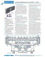
The <strong>Cobalt</strong> & <strong>Onyx</strong> ArchitectureTTL Gate / TrigTTL Sync / PPSSample C kResetGate A/DGate D/ASync / PPS A/DSync / PPS D/ATiming BusSample Clk /Reference Clk InA/D Clock/Sync BusD/A Clock/Sync BusA/DRF InRFXFORMRRF InRFXFORMRA/DRFXFORMRD/ARF OutRFXFORMRD/ADIGITALUPCONVERTERRF OutVCXOTIMING BUSGENERATORClock / Sync /Gate / PPSONYX: VIRTEX-7 FPGAVX330T, VX485T or V 690TGTXGTXGTXLVDSCONFIGFLASH1GBONYXOnlyFPGAConfigBus8XGATEXPRESS PCIeCONFIGURATIONMANAGERPCIeP15XMC4X4XOption-105SerialI/OP16XMC40 <strong>Cobalt</strong>48 <strong>Onyx</strong>Option-104FPGAGPIOP14PMCDDR3SDRAM1GB32 32 32 32DDR3SDRAM1GBDDR3SDRAM1GBDDR3SDRAM1GBGateXpress a r ess for f FPGA Configurationi a oThe <strong>Onyx</strong> architecture includes GateXpress,a sophisticated FPGA-PCIe configurationmanager for loading and reloading theFPGA. At power up, GateXpress immediatelypresents a PCIe target for thehost computer to discover, effectivelygiving the FPGA time to load fromFLASH.This is especially important for largerFPGAs where the loading times canexceed the PCIe discovery window,typically 100 msec on most PCs.The board’s configuration FLASHcan hold four FPGA images. Images canbe factory-installed IP or custom IPcreated by the user, and programmedinto the FLASH via JTAG using XilinxiMPACT or through the board’s PCIeinterface. At power up the user canchoose which image will load based ona hardware switch setting.Once booted, GateXpress allowsthe user three options for dynamicallyreconfiguring the FPGA with a new IPimage. The first is the option to load analternate image from FLASH throughsoftware control. The user selects thedesired image and issues a reloadcommand.The second option is for applicationswhere the FPGA image must be loadeddirectly through the PCIe interface. Thisis important in security situations wherethere can be no latent user image leftin nonvolatile memory when power isremoved. In applications where theFPGA IP may need to change manytimes during the course of a mission,images can be stored on the host computerand loaded through PCIe as needed.The third option, typically used duringdevelopment, allows the user to directlyload the FPGA through JTAG using XilinxiMPACT.In all three FPGA loading scenarios,GateXpress handles the hardware negotiationsimplifying and streamlining theloading task. In addition, GateXpresspreserves the PCIe configuration spaceallowing dynamic FPGA reconfigurationwithout needing to reset the hostcomputer to rediscover the board.After the reload, the host simply continuesto see the board with the expecteddevice ID.7
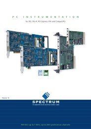
The <strong>Cobalt</strong> & <strong>Onyx</strong> ArchitectureFPGA A Dataflowaf All of the board’s data and control pathsare accessible by the FPGA, enablingfactory-installed functions including datamultiplexing, channel selection, datapacking, gating, triggering, and memorycontrol. The <strong>Cobalt</strong> & <strong>Onyx</strong> Architectureorganizes the FPGA as a container fordata processing applications whereeach function exists as an intellectualproperty (IP) module.Each member of the <strong>Cobalt</strong>/<strong>Onyx</strong>family is delivered with factory-installedapplications ideally matched to theboard’s analog interfaces. Dependingon model, the factory-installed functionsmay include A/D acquisition and D/Awaveform playback IP modules. IP modulesfor either DDR3 or QDRII+ (<strong>Cobalt</strong>only) memories, a controller for alldata clocking and synchronization functions,a test signal generator, and aPCIe interface complete the factoryinstalledfunctions and enable theboard to operate as a complete turnkeysolution without the need to developany FPGA IP.For applications that require specializedfunctions, users can install customIP for data processing. <strong>Pentek</strong> GateFlow ®FPGA Design Kits (described later inthis catalog) include all of the factoryinstalled modules as documentedsource code. Developers can integratetheir IP with the <strong>Pentek</strong> factory-installedfunctions or use the GateFlow to completelyreplace the <strong>Pentek</strong> IP with theirs.A/D Acquisition q nIP Moduleso uThis typical <strong>Cobalt</strong>/<strong>Onyx</strong> moduleincludes two A/D Acquisition IPmodules for easy capture and datamoving. Each IP module can receivedata from either of the two A/Ds, atest signal generator or from the D/AWaveform Playback IP Module inloopback mode. Each IP modulehas an associated memory bank forbuffering data in FIFO mode or forstoring data in transient capture mode.All memory banks are supportedwith DMA engines for moving A/Ddata through the PCIe interface.These powerful linked-list DMAengines are capable of a uniqueAcquisition Gate Driven mode. Inthis mode, the length of a transferperformed by a link definition neednot be known prior to data acquisition;rather, it is governed by the length ofthe acquisition gate. This is extremelyuseful in applications where an externalgate drives acquisition and theexact length of that gate is not knownor is likely to vary.For each transfer, the DMA enginecan automatically construct metadatapackets containing A/D channel ID, asample-accurate time stamp, and datalength information. These actionssimplify the host processor’s job ofidentifying and executing on the data.MEMORYCONTROLtoMemBank 1DATAPACKING& FLOWCONTROLMETADATAGENERATORMUXLINKED-LISTDMA ENGINEA/DACQUISITIONIP MODULE 1fromA/D Ch 1fromA/D Ch 2INPUT MULTIPLEXERMEMORYCONTROLtoMemBank 2DATAPACKING& FLOWCONTROLMETADATAGENERATORLINKED-LISTDMA ENGINEA/DACQUISITIONIP MODULE 2D/A Wa aveform o Playback l y c k IP ModuleeFactory-installed functions for thistypical <strong>Cobalt</strong>/<strong>Onyx</strong> module include asophisticated D/A Waveform PlaybackIP module. A linked-list controllerallows users to easily play back waveformsstored in either on-board memoryor off- board host memory to thedual D/As.Parameters including length of waveform,delay from playback trigger,waveform repetition, etc. can beprogrammed for each waveform.Up to 64 individual link entriescan be chained together to createcomplex waveforms with a minimumof programming.D/A loopbackMUXTESTSIGNALGENERATORMEMORYCONTROLtoMemBank 3toD/ADATAUNPACKING& FLOWCONTROLMUXLINKED-LISTDMA ENGINED/AWAVEFORMPLAYBACKIP MODULEVIRTEX-6/VIRTEX-7 FPGA DATAFLOW DETAILPCIe INTERFACE(supports user installed IP)MemoryBank 1MemoryBank 2MemoryBank 3MemoryBank 4PCIe8X 4X 4X 40GigabitSerial I/OFPGAGPIO8
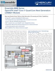
<strong>Cobalt</strong> & <strong>Onyx</strong> Formats & InterfacesXMC CFormatHere is a photograph of the typicalboard reviewed in detail in the previoussection. In its XMC configuration, each<strong>Cobalt</strong> or <strong>Onyx</strong> module complies withthe VITA 42.0 XMC specification andis suitable for mounting on motherboardswith PMC/XMC connectors.All XMC modules are available incommercial and in several ruggedizationlevels up to and including conductioncooling.TTL Gate / TrigTTL Sync / PPSSample ClkResetGate A/DGate D/ASync / PPS A/DSync / PPS D/ATiming BusSample Clk /Reference Clk InA/D Clock/Sync BusD/A Clock/Sync BusA/DRF InRFXFORMRRFXFORMRA/DRF InRFXFORMRD/ARF OutRFXFORMRD/ADIGITALUPCONVERTERRF OutVCXOTIMING BUSGENERATORClock / Sync /Gate / PPSGTXGTXCOBALT: VIRTEX-6 FPGALX130T, LX240T, LX365T, SX315T or SX475TONYX: VIRTEX-7 FPGAVX330T, VX485T or V 690TGTX GTXLVDSCONFIGFLASH1GBONYXOnlyFPGAConfigBus8XGATEXPRESS PCIeCONFIGURATIONMANAGERPCIeP15XMC16CONFIGFLASH64 MBCOBALTOnly8XPCIeP15XMC4X4XOption-105SerialI/OP16XMC40 <strong>Cobalt</strong>48 <strong>Onyx</strong>Option-104FPGAGPIOP14PMC16QDRII+SRAM8MBDDR3SDRAM512 MB1616QDRII+SRAM8MBDDR3SDRAM512 MB1616QDRII+SRAM8MB<strong>Cobalt</strong> Memory ConfigurationsDDR3SDRAM512 MB1616QDRII+SRAM8MBDDR3SDRAM512 MB16<strong>Onyx</strong> Memory ConfigurationPCI Express r s Interfacee ceThe <strong>Cobalt</strong> XMC includes an industrystandardinterface fully compliant withPCI Express Gen. 1 & 2 bus specifications.Gen. 2 provides 4 GB/sec peak datatransfer rate.The <strong>Onyx</strong> XMC includes an industrystandardinterface fully compliant withPCI Express Gen. 1, 2 & 3 bus specifications.Gen. 3 provides 8 GB/sec peaktransfer rate.The PCIe interface includes multipleDMA controllers for efficient transfersto and from the module.XMC InterfacenaDDR3SDRAM1GBBoth <strong>Cobalt</strong> and <strong>Onyx</strong> XMC productscomply with the VITA 42.0 XMC specification.Each of the two connectorsprovides dual 4X links or a single 8X link.With dual XMC connectors, the XMCproducts support both x4 and x8 PCIeon the first XMC connector leaving thesecond connector free to support userinstalledtransfer protocols specific tothe target application.DDR3SDRAM1GBDDR3SDRAM1GBDDR3SDRAM1GBOptional l Interfacese aceOption -104 installs the P14 PMCconnector with 20 pairs of LVDS connections(<strong>Cobalt</strong>) or 24 pairs (<strong>Onyx</strong>) tothe FPGA for custom I/O.Option -105 installs the P16 XMCconnector with a single 8X or dual 4Xgigabit links to the FPGA to supportserial protocols.9
<strong>Cobalt</strong> & <strong>Onyx</strong> Formats & InterfacesPCI IExpress s s FormatThe PCI Express format shown here issuitable for mounting in PCs with PCIeconnectors and interfaces. Physically,the XMC module reviewed in the previouspage is mounted on a PCI Express “carrier”board with x8 PCIe motherboard connectors.Other connectors on this boardprovide additional interfaces as describedbelow.The unique design of the PCIe carrierincludes an integrated fan that keepsthe module cool even in demandingsituations while still requiring a singlePCIe slot.TTL Gate / TrigTTL Sync / PPSSample ClkResetGate A/DGate D/ASync / PPS A/DSync / PPS D/ATiming BusSample Clk /Reference Clk InA/D Clock/Sync BusD/A Clock/Sync BusA/DRF InRFXFORMRRFXFORMRA/DRF InRFXFORMRD/ARF OutRFXFORMRD/ADIGITALUPCONVERTERRF OutVCXOTIMING BUSGENERATORClock / Sync /Gate / PPSGTXGTXCOBALT: VIRTEX-6 FPGALX130T, LX240T, LX365T, SX315T or SX475TONYX: VIRTEX-7 FPGAVX330T, VX485T or V 690TGTX GTXLVDSCONFIGFLASH1GBFPGAConfigBus8XGATEXPRESS PCIeCONFIGURATIONMANAGER16CONFIGFLASH64 MB8XPCIe4X4XOption-105SerialI/O40 <strong>Cobalt</strong>48 <strong>Onyx</strong>Option-104FPGAGPIO16QDRIISRAM8MB1616QDRIISRAM8MB1616QDRIISRAM8MB16<strong>Cobalt</strong> Memory Configurations16QDRIISRAM8MB16ONYXOnlyPCIeCOBALTOnlyDual 4XSerialConn68-pinHeaderDDR3SDRAM512 MBDDR3SDRAM512 MBDDR3SDRAM512 MBDDR3SDRAM512 MBx8 PCI Expressx8 PCI ExpressDDR3SDRAM1GB<strong>Onyx</strong> Memory ConfigurationDDR3SDRAM1GBDDR3SDRAM1GBDDR3SDRAM1GBPCI Express r s Interfacee ceThe <strong>Cobalt</strong> PCIe board includes anindustry-standard interface fully compliantwith PCI Express Gen. 1 & 2 busspecifications. Gen. 2 provides 4 GB/secpeak data transfer rate.The <strong>Onyx</strong> PCIe board includes anindustry-standard interface fully compliantwith PCI Express Gen. 1, 2 & 3bus specifications. Gen. 3 provides8 GB/sec peak transfer rate.The PCIe interface includes multipleDMA controllers for efficient transfersto and from the module.Optional l InterfaceseceOption -104 connects 20 pairs of LVDSconnections (<strong>Cobalt</strong>) or 24 pairs (<strong>Onyx</strong>)from the FPGA on PMC P14 to a 68-pinDIL ribbon-cable header on the PCIeboard for custom I/O.Option -105 connects two 4X gigabitserial links from the FPGA on XMCP16 to two 4X gigabit serial connectorsalong the top edge of the PCIe board.10
<strong>Cobalt</strong> & <strong>Onyx</strong> Formats & Interfaces3U 3 OpenVPX Formatr atThe OpenVPX format is compatiblewith several VITA standards including:VITA-46, VITA-48 andVITA-65 (OpenVPX TM SystemSpecification)Shown here is the 3U OpenVPX COTSversion (left) and the rugged versionwhich is available in several ruggedizationlevels up to and includingconduction cooling.TTL Gate / TrigTTL Sync / PPSSample ClkResetGate A/DGate D/ASync / PPS A/DSync / PPS D/ATiming BusSample Clk /Reference C k InA/D Clock/Sync BusD/A Clock/Sync BusA/DRF InRFXFORMRRFXFORMRA/DRF InRFXFORMRD/ARF OutRFXFORMRD/ADIGITALUPCONVERTERRF OutVCXOTIMING BUSGENERATORClock / Sync /Gate / PPSGTXCOBALT: VIRTEX-6 FPGALX130T, LX240T, LX365T, SX315T or SX475TGTXONYX: VIRTEX-7 FPGAVX330T, VX485T or V 690TGTXGTXLVDSCONFIGFLASH1GBFPGAConfigBusONYXOnlyPCIe8XGATEXPRESS PCIeCONFIGURATIONMANAGERVPX BACKPLANE16CONFIGFLASH64 MBCOBALTOnlyCROSSBARSWITCH4X 4XGbit GbitSerial SerialVPX-P18XPCIe4XGbitSerial4X4XGbitSerial4XOption-105SerialI/O40VPX-P2Option-104FPGAGPIO16QDRIISRAM8MBDDR3SDRAM512 MBDDR3SDRAM1GB1616QDRIISRAM8MBDDR3SDRAM512 MBDDR3SDRAM1GB1616QDRIISRAM8MB16<strong>Cobalt</strong> Memory ConfigurationsDDR3SDRAM512 MB<strong>Onyx</strong> Memory ConfigurationDDR3SDRAM1GB16QDRIISRAM8MBDDR3SDRAM512 MBDDR3SDRAM1GB16PCI Express r s Interfacee The <strong>Cobalt</strong> 3U OpenVPX board includesan industry-standard interface fullycompliant with PCI Express Gen. 1 & 2bus specifications. Gen. 2 provides4 GB/sec peak data transfer rate.The <strong>Onyx</strong> 3U OpenVPX boardincludes an industry-standard interfacefully compliant with PCI Express Gen.1, 2 & 3 bus specifications. Gen. 3provides 8 GB/sec peak transfer rate.The PCIe interface includes multipleDMA controllers for efficient transfersto and from the board.Fabric-T ransparent n a n Crossbar C sb r SwitchThe 3U OpenVPX <strong>Cobalt</strong> or <strong>Onyx</strong> boardfeatures a unique high-speed switchingconfiguration. A fabric-transparent crossbarswitch bridges numerous interfacesand components on the board usinggigabit serial data paths with no latency.Programmable signal input equalizationand output pre-emphasis settingsenable optimization. Data paths canbe selected as single (1X) lanes, orgroups of four lanes (4X) for routingover to the VPX-P1 connector.11Optional i aInterfacesI t a eOption -104 provides 20 pairs of LVDSconnections between the FPGA and theVPX-P2 connector for custom I/O.Option -105 connects two 4X gigabitserial links from the FPGA on XMCP16 to the crossbar switch for routingto VPX-P1.
<strong>Cobalt</strong> & <strong>Onyx</strong> Formats & InterfacesCompactPCI I Formatsr aAs shown here, the CompactPCI formatis available in three configurations:■ 6U cPCI with double density; thisconfiguration mounts two XMCmodules on a 6U carrier board.■ 6U cPCI with single density; thisconfiguration mounts only oneXMC module on a 6U carrierboard.■ 3U cPCI mounts one XMC moduleon a 3U carrier boardIn order to describe these three configurationsin more detail, we have omittedthe components and circuitry shown inthe previous three formats; we just showthe Virtex-6/Virtex-7 FPGAs with theexternal connections that define thestandard and optional interfaces.LVDSVIRTEX-6/VIRTEX-7 FPGA1st XMC MODULEGTXGTXVIRTEX-6/VIRTEX-7 FPGA2nd XMC MODULEGTX GTXLVDS6U 6 cPCI C Double u e DensitynTwo PCIe-to-PCI bridges connect thex4 PCIe interfaces from each XMCmodule to a PCI-to-PCI bridge. Thisbridge connects both modules to the32- or 64-bit, 33/66 MHz PCI/PCI-X bus.40 FPGAx4x4FPGAx4x440ConfigPCIe PCIePCIeConfigPCIeBusBusOption-104FPGAGPIOCONFIGFLASH1GBcPCI J3ONYX OnlyGATEXPRESS PCIeCONFIGURATIONMANAGERx4 PCIePCIeto PCIBRIDGE6U cPCI C Optional t o l Interfacee eCONFIGFLASH64 MBCOBALT OnlyPCI/PCI-X BusOption -104 provides 20 pairs of LVDSconnections between the FPGA and theJ3 connector for custom I/O.The J5 connector supports Option-104 for the 2nd XMC module.PCIto PCIBRIDGECONFIGFLASH64 MBCOBALT OnlyPCIeto PCIBRIDGE32/64-bit, 33/66 MHzGATEXPRESS PCIeCONFIGURATIONMANAGERx4 PCIe6U cPCI I Single e Densityn CONFIGFLASH1GBONYX OnlyOption-104FPGAGPIOcPCI J5The 2nd XMC module, its associatedPCIe-to-PCI bridge and the optionalinterface connection to J5 are notpresent.LVDSVIRTEX-6/VIRTEX-7 FPGAGTXGTX40Option-104FPGAGPIOCONFIGFLASH1GBONYX OnlyFPGAConfigBusGATEXPRESS PCIeCONFIGURATIONMANAGERx4PCIex4 PCIex4PCIePCIeto PCIBRIDGECONFIGFLASH64 MBCOBALT Only3U 3 cPCI c C Single l e Densityn yA PCIe-to-PCI bridge connects the x4PCIe interface from the XMC moduleto the 32-bit, 33/66 MHz PCI/PCI-X bus.cPCI J3PCI/PCI-X Bus32-bit, 33/66 MHz3U cPCI C Optional t n Interfacene cOption -104 provides 20 pairs of LVDSconnections between the FPGA andthe J3 connector for custom I/O.12
Models 71620 6 0 & 71720: 1 2 : Transceiver i v r with Three e A/Ds, D DUC, , T wo D/As / s - XMCFeaturessModel 71620 Model 71620 is a member of the <strong>Cobalt</strong>family of high performance XMC modulesbased on the Xilinx Virtex-6 FPGA.Model 71720 is a member of the <strong>Onyx</strong>family of high-performance modulesbased on the Virtex-7 FPGA.These multichannel, high-speed dataconverters, it is suitable for connectionto HF or IF ports of a communicationsor radar system. Their built-in datacapture and playback features offer anideal turnkey solution.Each model includes three A/Ds,one DUC, two D/As and four banks ofmemory. In addition to supporting PCIExpress as a native interface, these modelsinclude general-purpose and gigabitserial connectors for applicationspecificI/O.Model 71720■ Complete radar and software radiointerface solution■ Supports Xilinx Virtex-6 LXT andSXT or Virtex-7 VXT FPGAs■ Model 71720: GateXpress supportsdynamic FPGA reconfigurationacross PCIe■ Three 200 MHz 16-bit A/Ds■ One digital upconverter■ Two 800 MHz 16-bit D/As■ Model 71620: Up to 2 GB ofDDR3 SDRAM or 32 MB ofQDRII+ SRAM; Model 71720:4 GB of DDR3 SDRAM■ Sample clock synchronization to anexternal system reference■ LVPECL clock/sync bus formultimodule synchronization■ Model 71620: PCI Express (Gen. 1& 2) interface up to x8; Model71720: PCI Express (Gen. 1, 2,and 3) interface up to x8■ Optional user-configurable gigabitserial interface■ Optional LVDS connections to theVirtex-6 FPGA for custom I/OA/D ConvertersC v t sThe front end accepts three full-scaleanalog HF or IF inputs on front panelSSMC connectors at +8 dBm into 50ohms with transformer coupling intothree Texas Instruments ADS5485200 MHz, 16-bit A/D converters.The digital outputs are delivered intothe Virtex-6 FPGA for signal processing,data capture or for routing to othermodule resources.Sample C k /Reference Clk InTTL Gate / TrigTTL Sync / PPSSample ClkResetGate A/DGate D/ASync / PPS A/DSync / PPS D/ATiming BusTIMING BUSGENERATORClock / Sync /Gate / PPSVCXOCONFIGFLASH1GBA/DClock/SyncBusD/AClock/SyncBusONYXOnlyFPGAConfigBusGTXPCIeP15XMC8XGATEXPRESS PCIeCONFIGURATIONMANAGERRF In RF In RF In RF Out RF OutRFXFORMR200 MHz16 BIT A/D1616CONFIGFLASH64 MBCOBALTOnlyGTXCOBALT: VIRTEX-6 FPGALX130T, LX240T, LX365T, SX315T or SX475T8XRFXFORMR200 MHz16 BIT A/DPCIeP15XMCDigital g a Upconverter e e and D/AsA TI DAC5688 DUC (digital upconverter)and D/A accepts a baseband real or complexdata stream from the FPGA which isoptionally interpolated, upconverted andthen delivered to the two D/As.When operating as a DUC, it interpolatesand translates real or complexbaseband input signals to any IF centerfrequency up to 360 MHz. It deliversreal or quadrature (I+Q) digital outputsto the dual 16-bit D/A converter. Analogoutput is through a pair of front panelSSMC connectors.If translation is disabled, the DAC5688acts as a dual interpolating 16-bit D/Awith output sampling rates up to 800 MHz.In both modes the DAC5688 providesinterpolation factors of 2x, 4x and 8x.16ONYX: VIRTEX-7 FPGAVX330T, VX485T or V 690TGTX GTX LVDS4X4XOption-105SerialI/OP16XMCRFXFORMR200 MHz16 BIT A/D1640 Coba t48 <strong>Onyx</strong>Option-104FPGAGPIOP14PMC16QDRII+SRAM8MBDDR3SDRAM512 MB800 MHz 800 MHz16 BIT D/A 16 BIT D/ADIGITALUPCONVERTER16RFXFORMR16QDRII+SRAM8MBDDR3SDRAM512 MB1632RFXFORMR16QDRII+SRAM8MB16<strong>Cobalt</strong> Memory ConfigurationsDDR3SDRAM512 MB16QDRII+SRAM8MBDDR3SDRAM512 MB16Contact <strong>Pentek</strong> for availability of ruggedand conduction-cooled versionsDDR3SDRAM1GB<strong>Onyx</strong> Memory ConfigurationDDR3SDRAM1GBDDR3SDRAM1GBDDR3SDRAM1GB14
Models o 716207 6 & 71720: : T ransceiver e with h Three T e A/Ds, / DUC, C T wo D/As / A s- XMCCInstalled n t d I IP Modulesu sThe factory-installed functions in bothmodels include three A/D acquisitionand a D/A waveform playback IP modules,ideally matched to the board’sanalog interfaces.IP modules for either DDR3 orQDRII+ memories, a controller for alldata clocking and synchronizationfunctions, a test signal generator, and aPCIe interface complete the factoryinstalledfunctions and enable thesemodels to operate as a complete turnkeysolution, without the need todevelop any FPGA IP.A/D Acquisition u i IP P Moduleso Both models feature three A/D AcquisitionIP Modules for easily capturingand moving data. Each module canreceive data from any of the threeA/Ds, a test signal generator or fromthe D/A Waveform Playback IP Modulein loopback mode.Each IP module has an associatedmemory bank for buffering data inFIFO mode or for storing data in transientcapture mode. All memorybanks are supported with DMAengines for easily moving A/D datathrough the PCIe interface.These powerful linked-list DMAengines are capable of a uniqueAcquisition Gate Driven mode. In thismode, the length of a transfer performedby a link definition need notbe known prior to data acquisition;rather, it is governed by the length ofthe acquisition gate. This is extremelyuseful in applications where an externalgate drives acquisition and theexact length of that gate is not knownor is likely to vary.For each transfer, the DMA enginecan automatically construct metadatapackets containing A/D channel ID,a sample-accurate time stamp and datalength information. These actionssimplify the host processor’s job ofidentifying and executing on the data.MEMORYCONTROLtoMemBank 1DATAPACKING& FLOWCONTROLMETADATAGENERATORMUXLINKED-LISTDMA ENGINEA/DACQUISITIONIP MODULE 1fromA/D Ch 1MEMORYCONTROLtoMemBank 2fromA/D Ch 2fromA/D Ch 3INPUT MULTIPLEXERDATAPACKING& FLOWCONTROLMETADATAGENERATORMUXLINKED-LISTDMA ENGINEA/DACQUISITIONIP MODULE 2D/A W aveform a o Playback l IP ModulelThe factory-installed functions in bothmodels include a sophisticated D/AWaveform Playback IP module. Alinked-list controller allows users toeasily play back to the dual D/Aswaveforms stored in either on-boardmemory or off-board host memory.Parameters including length ofwaveform, delay from playback trigger,waveform repetition, etc. can be programmedfor each waveform.Up to 64 individual link entriescan be chained together to create complexwaveforms with a minimum ofprogramming.D/A loopbackMEMORYCONTROLtoMemBank 3DATAPACKING& FLOWCONTROLMETADATAGENERATORMUXLINKED-LISTDMA ENGINEA/DACQUISITIONIP MODULE 3TESTSIGNALGENERATORMEMORYCONTROLtoMemBank 4toD/ADATAUNPACKING& FLOWCONTROLMUXLINKED-LISTDMA ENGINED/AWAVEFORMPLAYBACKIP MODULEVIRTEX-6/VIRTEX-7 X FPGA DATAFLOW DETAILPCIe INTERFACE(supports user installed IP)MemoryBank 1MemoryBank 2MemoryBank 3MemoryBank 4PCIe8X 4X 4X 40 Model 71620GigabitSerial I/OFPGAGPIO48 Model 7172015
Models 71620 6 0 & 71720: 1 2 : Transceiver i v r with Three e A/Ds, D DUC, , T wo D/As / s - XMCAlso o A vailableabSpecificationsp c f icioModel 746206U cPCIModel 78620x8 PCI ExpressModel 53620 3U VPXCOTS and ruggedModel 53720 3U VPXCOTS and ruggedModel 737203U cPCIFront Panel Analog Signal InputsInput Type: Transformer-coupled,front panel female SSMC connectorsTransformer Type: Coil CraftWBC4-6TLBFull Scale Input: +8 dBm into50 ohms3 dB Passband: 300 kHz to 700 MHzA/D ConvertersType: Texas Instruments ADS5485Sampling Rate: 10 MHz to 200 MHzResolution: 16 bitsD/A ConvertersType: Texas Instruments DAC5688Input Data Rate: 250 MHz max.Output IF: DC to 400 MHz max.Output Signal: 2-channel real or1-channel with frequency translationOutput Sampling Rate: 800 MHzmax. with interpolationResolution: 16 bitsFront Panel Analog Signal OutputsOutput Type: Transformer-coupled,front panel female SSMC connectorsTransformer Type: Coil CraftWBC4-6TLBFull Scale Output: +4 dBm into50 ohms3 dB Passband: 300 kHz to 700 MHzSample Clock Sources: On-board clocksynthesizer generates two clocks:one A/D clock and one D/A clockClock SynthesizerClock Source: Selectable from onboardprogrammable VCXO (10 to810 MHz), front panel externalclock or LVPECL timing busSynchronization: VCXO can be lockedto an external 4 to 180 MHz PLLsystem reference, typically 10 MHzClock Dividers: External clock orVCXO can be divided by 1, 2, 4, 8,or 16, independently for the A/Dclock and D/A clockExternal ClockType: Front panel female SSMC connector,sine wave, 0 to +10 dBm,AC-coupled, 50 ohms, accepts 10to 800 MHz divider input clock orPLL system referenceTiming Bus: 26-pin connector LVPECLbus includes, clock/sync/gate/PPSinputs and outputs; TTL signal forgate/trigger and sync/PPS inputsModel 71620 FPGAStandard: CXC6VLX130TOptional: Xilinx Virtex-6XC6VLX240T, XC6VLX365T,XC6VSX315T, or XC6VSX475TModel 71720 FPGAStandard: Xilinx Virtex-7XC7VX485T-2Optional: Xilinx Virtex-7XC7VX330T-2 or XC7VX690T-2Custom I/OOption -104: Installs the PMC P14connector with 20 LVDS pairs ( Model71620) or 24 pairs (Model 71720)to the FPGAOption -105: Installs the XMC P16connector configurable as one 8Xor two 4X gigabit serial links to theFPGAMemoryModel 71620Option 150 or 160: Two 8 MBQDRII+ SRAM memory banks,400 MHz DDROption 155 or 165: Two 512 MBDDR3 SDRAM memory banks,400 MHz DDRModel 71720Type: DDR3 SDRAMSize: Four banks, 1 GB eachPCI-Express InterfaceModel 71660PCI Express Bus: Gen. 1: x4 or x8;Gen. 2: x4Model 71760PCI Express Bus: Gen. 1, 2 or 3: x4or x8; Gen. 3 available only withthe VX330T-2 or VX690T-2 FPGAsEnvironmentalOperating Temp: 0° to 50° CStorage Temp: –20° to 90° CRelative Humidity: 0 to 95%, noncond.Size: Standard XMC module, 2.91 in. x5.87 in.16
Model 71621: 6 1 T ransceiver r c e e with h Three e A/Ds, / DDCs, D C , DUC, , Two D/As / s- XMCCThe model 71621 consists of a Model71620 as described previously, but withthe addition of three multiband DDCs,one interpolator and one beamformerIP Cores installed in the Virtex-6 FPGA.These IP Cores are in addition to thefactory-installed IP Modules describedin the Model 71620.DDC IP P CoresrWithin each A/D Acquisition IPModule is a powerful DDC IP core.Because of the flexible input routingof the A/D Acquisition IP Modules,many different configurations can beachieved including one A/D drivingall three DDCs or each of the threeA/Ds driving its own DDC.Each DDC has an independent32-bit tuning frequency setting thatranges from DC to ƒ s , where ƒ s isthe A/D sampling frequency. EachDDC can have its own unique decimationsetting, supporting as many asthree different output bandwidths forthe board. Decimations can be programmedfrom 2 to 65,536 providing awide range to satisfy most applications.The decimating filter for eachDDC accepts a unique set of usersupplied18-bit coefficients. The 80%default filters deliver an output bandwidthof 0.8*ƒ s /N, where N is thedecimation setting. The rejection ofadjacent-band components withinthe 80% output bandwidth is betterthan 100 dB. Each DDC delivers acomplex output stream consisting of24-bit I + 24-bit Q or16-bit I + 16-bitQ samples at a rate of ƒ s /N.Interpolator n e l o IP I CoreoThe DAC5688 provides interpolationfactors of 2x, 4x and 8x. In additionto the DAC5688, an FPGA-basedinterpolator core provides additionalinterpolation from 2x to 65,536x.The two interpolators can be combinedto crate a total range from 2x to524,288x.Beamformer a o m IP CoreC rIn addition to the DDCs, the 71621features a complete beamformingsubsystem. Each DDC core containsprogramable I & Q phase and gainadjustments followed by a power meterthat continuously measures the individualaverage power output. The timeconstant of the averaging interval foreach meter is programmable up to 8Ksamples. The power meters presentaverage power measurements for eachDDC core output in easy-to-readregisters.4Xto nextboardMEMORYCONTROLtoMemBank 1AURORAGIGABITSERIALINTERFACEsum outsum inDDCDEC: 2 TO 65536A/DACQUISITIONIP MODULE 1SUMMERBEAMFORMER CORE4Xfrom previousboardfromA/D Ch 1fromA/D Ch 2fromA/D Ch 3INPUT MULTIPLEXERDDCDEC: 2 TO 65536A/DACQUISITIONIP MODULE 2In addition, each DDC core includesa threshold detector to automaticallysend an interrupt to the processor ifthe average power level of any DDCcore falls below or exceeds a programmablethreshold.A programmable summationblock provides summing of any of thethree DDC core outputs. An additionalprogrammable gain stage compensatesfor summation change bit growth.A power meter and threshold detectblock is provided for the summedoutput. The output is then directed backinto the A/D Acquisition IP Module 1FIFO for reading over the PCIe. Forlarger systems, multiple 71621’s canbe chained together via a built-inXilinx Aurora gigabit serial interfacethrough the P16 XMC connector. Thisallows summation across channels onmultiple boards.D/A loopbackVIRTEX-6 FPGA DATAFLOW DETAILDDCDEC: 2 TO 65536A/DACQUISITIONIP MODULE 3TESTSIGNALGENERATORMUXPOWERPOWERPOWERIP COREMETER &METER &METER &THRESHOLDTHRESHOLDTHRESHOLDDATA UNPACKINGDETECTDETECTDETECT& FLOW CONTROLDDC CORE DDC CORE DDC COREDATA PACKING &DATA PACKING &DATA PACKING &MUXFLOW CONTROLFLOW CONTROLFLOW CONTROLMEMORYMEMORYCONTROLCONTROLMETADATAMETADATAMEMORYMETADATAGENERATOR MUXto GENERATOR MUXto GENERATOR MUX CONTROLMemMemto LINKED-LISTLINKED-LIST Bank 2 LINKED-LIST Bank 3 LINKED-LIST Mem DMA ENGINEDMA ENGINEDMA ENGINEDMA ENGINEBank 4D/APCIe INTERFACEWAVEFORMPLAYBACKIP MODULE8XPCIetoD/AINTERPOLATOR2 TO 6553617
Model e l 71621: 6 1 T ransceiver r e with h Three h e A/Ds, / s , DDCs, D C DUC, , T wo D/As / s - XMCCAlso o A vailableabSpecificationsp c ficioModel 746216U cPCIModel 78621x8 PCI ExpressModel 53621 3U VPXCOTS and ruggedModel 736213U cPCIFront Panel Analog Signal InputsInput Type: Transformer-coupled,front panel female SSMC connectorsTransformer Type: Coil CraftWBC4-6TLBFull Scale Input: +8 dBm into 50 ohms3 dB Passband: 300 kHz to 700 MHzA/D ConvertersType: Texas Instruments ADS5485Sampling Rate: 10 MHz to 200 MHzResolution: 16 bitsDigital DownconvertersQuantity: Three channelsDecimation Range: 2x to 65,536x intwo stages of 2x to 256xLO Tuning Freq. Resolution: 32 bits,0 to ƒ sLO SFDR: >120 dBPhase Offset Resolution: 32 bits,0 to 360 degreesFIR Filter: 18-bit coefficients, 24-bitoutput, with user programmable coefficientsDefault Filter Set: 80% bandwidth,100 dBstopband attenuationD/A ConvertersType: Texas Instruments DAC5688Input Data Rate: 250 MHz max.Output IF: DC to 400 MHz max.Output Signal: 2-channel real or1-channel with frequency translationOutput Sampling Rate: 800 MHzmax. with 2x, 4x or 8x interpolationResolution: 16 bitsDigital InterpolatorInterpolation Range: 2x to 65,536xin two stages of 2x to 256xBeamformerSummation: Three channels on-board;multiple boards can be summed viaSummation Expansion ChainSummation Expansion Chain: Onechain in and one chain out link viaXMC connector using Aurora protocolPhase Shift Coefficients: I & Qwith 16-bit resolutionGain Coefficients: 16-bit resolutionChannel Summation: 24-bitMultiboard Summation Expansion:32-bitFront Panel Analog Signal OutputsOutput: Transformer-coupled, frontpanel female SSMC connectorsTransformer: Coil Craft WBC4-6TLBFull Scale Output: +4 dBm into50 ohms3 dB Passband: 300 kHz to 700 MHzSample Clock Sources: On-board clocksynthesizer generates two clocks:one A/D clock and one D/A clockClock SynthesizerClock Source: Selectable from onboardprogrammable VCXO (10 to810 MHz), front panel externalclock or LVPECL timing busSynchronization: VCXO can belocked to an external 4 to 180 MHzPLL system reference, typically 10 MHzClock Dividers: External clock orVCXO can be divided by 1, 2, 4, 8,or 16, independently for the A/Dclock and D/A clockExternal ClockType: Front panel female SSMC connector,sine wave, 0 to +10 dBm,AC-coupled, 50 ohms, accepts 10to 800 MHz divider input clock orPLL system referenceTiming Bus: 26-pin connector LVPECLbus includes, clock/sync/gate/PPSinputs and outputs; TTL signal forgate/trigger and sync/PPS inputsField Programmable Gate ArrayStandard: Xilinx Virtex-6XC6VLX240TOptional: Xilinx Virtex-6XC6VLX365T, XC6VSX315T, orXC6VSX475TCustom I/OOption -104: Installs the PMC P14connector with 20 LVDS pairs tothe FPGAMemoryOption 150 or 160: Two 8 MBQDRII+ SRAM memory banks,400 MHz DDROption 155 or 165: Two 512 MBDDR3 SDRAM memory banks,400 MHz DDRPCI-Express InterfacePCI Express Bus: Gen. 1: x4 or x8;Gen. 2: x4EnvironmentalOperating Temp: 0° to 50° CStorage Temp: –20° to 90° CRelative Humidity: 0 to 95%, noncond.Size: Standard XMC module, 2.91 in. x5.87 in.18
Model e 71630: 1 3 : 1 GHz z A/D, / , 1 GHz z D/A / A - XMCCModel 71630 is a member of the <strong>Cobalt</strong>family of high performance XMC modulesbased on the Xilinx Virtex-6 FPGA.A high-speed data converter, it is suitablefor connection to HF or IF ports ofa communications or radar system. Itsbuilt-in data capture and playbackfeatures offer an ideal turnkey solutionas well as a platform for developingand deploying custom FPGA processingIP.It includes 1 GHz A/D and D/A convertersand four banks of memory. Inaddition to supporting PCI ExpressGen. 2 as a native interface, the Model71630 includes optional general purposeand gigabit serial card connectorsfor application-specific I/O.Featuresar■■■■■■■■■■Complete radar and software radiointerface solutionSupports Xilinx Virtex-6 LXT andSXT FPGAsOne 1 GHz 12-bit A/DOne 1 GHz 16-bit D/AUp to 2 GB of DDR3 SDRAM or16 MB of QDRII+ SRAMSample clock synchronization to anexternal system referenceLVPECL sync bus for multimodulesynchronizationPCI Express (Gen. 1 & 2) interfaceup to x8Optional user-configurable gigabitserial interfaceOptional LVDS connections to theVirtex-6 FPGA for custom I/OContact <strong>Pentek</strong> for availability of ruggedand conduction-cooled versionsA/D Converteroe eThe front end accepts an analog HF orIF input on a front panel SSMC connectorwith transformer coupling into a TexasInstruments ADS5400 1 GHz, 12-bitA/D converter.The digital outputs are deliveredinto the Virtex-6 FPGA for signal processing,data capture or for routing to othermodule resources.Sample Clk /Reference Clk InTTLPPS/Gate/SyncGate InSync InA/D Sync BusGate InSync InD/A Sync BusTIMING BUSGENERATORClock / Sync /Gate / PPSVCXOA/D Clock/Sync BusD/A Clock/Sync Bus16DDR3SDRAM512 MB1616DDR3SDRAM512 MBVIRTEX-6 FPGALX130T, LX240T, LX365T, SX315T or SX475T16 16 16 16 16 16DDR3SDRAM512 MBD/A Convertero e rThe 71630 features a TI DAC5681Z1 GHz, 16-bit D/A. The converter hasan input sample rate of 1 GSPS, allowingit to acept full rate data from theFPGA. Additionally, the D/A includes a2x or 4x interpolation filter for applicationsthat provide 1/2 or 1/4 rate inputdata. Analog output is transformercoupledto a front panel SSMC connector.RF InRFXFORMR1 GHz12-BIT A/D12DDR3SDRAM512 MBConfigFLASH64 MBRF OutRFXFORMR1 GHz16-BIT D/AGTX8X16GTX GTX4X4XLVDS40Memory Banks 1&2 Memory Banks 3&4DDR3 option 155 DDR3 option 165QDRII+SRAM8MBQDRII+SRAM8MBQDRII+ option 150x8 PCIeP15XMCGigabitSerial I/O(option 105)P16XMCFPGAGPIO(option 104)P14PMC19
Model l 71630: 1 3 : 1 GHz z A/D, / , 1 GHz D/A A - XMCCInstalled I t a d IP Modulesd sThe 71630 factory-installed functionsinclude an A/D acquisition and a D/Awaveform playback IP module. Inaddition, IP modules for either DDR3or QDRII+ memories, a controller forall data clocking and synchronizationfunctions, a test signal generator and aPCIe interface complete the factoryinstalledfunctions and enable the71630 to operate as a completeturnkey solution, without the need todevelop any FPGA IP.A/D Acquisition i IP P Moduleo The 71630 features an A/D AcquisitionIP Module for easy capture anddata moving. The IP module canreceive data from the A/D, a testsignal generator, or from the D/AWaveform Playback IP Module inloopback mode. The IP module hasassociated memory banks for bufferingdata in FIFO mode or for storingdata in transient capture mode. Thememory banks are supported with aDMA engine for moving A/D datathrough the PCIe interface.This powerful linked-list DMAengine is capable of a unique AcquisitionGate Driven mode. In thismode, the length of a transfer performedby a link definition need notbe known prior to data acquisition;rather, it is governed by the length ofthe acquisition gate. This is extremelyuseful in applications where anexternal gate drives acquisition andthe exact length of that gate is notknown or is likely to vary.For each transfer, the DMA enginecan automatically construct metadatapackets containing a sample-accuratetime stamp, and data length information.These actions simplify thehost processor’s job of identifyingand executing on the data.MEMORYCONTROLLERtoMemBank 1toMemBank 2fromA/DDATAPACKING& FLOWCONTROLMETADATAGENERATORLINKED-LISTDMA ENGINED/A loopbackINPUT MULTIPLEXERMUXA/DACQUISITIONIP MODULEtoMemBank 3D/A / W aveform a Playback a ac k IP ModuleolThe Model 71630 factory-installedfunctions include a sophisticatedD/A Waveform Playback IP module.A linked-list controller allows usersto easily play back waveforms storedin either on-board memory or off- boardhost memory to the D/A.Parameters including length of waveform,delay from playback trigger,waveform repetition, etc. can beprogrammed for each waveform.Up to 64 individual link entriescan be chained together to createcomplex waveforms with a minimumof programming.MEMORYCONTROLLERTESTSIGNALGENERATORtoMemBank 4toD/ADATAUNPACKING& FLOWCONTROLMUXLINKED-LISTDMA ENGINED/AWAVEFORMPLAYBACKIP MODULEVIRTEX-6 FPGA DATAFLOW DETAILPCIe INTERFACE(supports user installed IP)MemoryBank 1MemoryBank 2MemoryBank 3MemoryBank 4PCIe8X 4X 4X 40GigabitSerial I/OFPGAGPIO20
Model e 71630: 1 3 : 1 GHz z A/D, / , 1 GHz z D/A / A - XMCCAlso o A vailableabSpecificationsp c ficioModel 746306U cPCIModel 78630x8 PCI ExpressModel 53630 3U VPXCOTS and ruggedModel 736303U cPCIFront Panel Analog Signal InputsInput Type: Transformer-coupled,front panel female SSMC connectorsA/D ConverterType: Texas Instruments ADS5400Sampling Rate: 100 MHz to 1 GHzResolution: 12 bitsD/A ConverterType: Texas Instruments DAC5681ZInput Data Rate: 1 GHz max.Interpolation Filter: bypass, 2x or 4xOutput Sampling Rate: 1 GHz max.Resolution: 16 bitsFront Panel Analog Signal OutputsOutput Type: Transformer-coupled,front panel female SSMC connectorsSample Clock Sources: On-boardclock synthesizer generates twoclocks: one A/D clock and one D/AclockClock SynthesizerClock Source: Selectable from onboardprogrammable VCXO or frontpanel external clockVCXO Frequency Ranges: 10 to945 MHz, 970 to 1134 MHz, and1213 to 1417 MHzSynchronization: VCXO can belocked to an external 4 to 200 MHzPLL system reference, typically10 MHzClock Dividers: External clock orVCXO can be divided by 1, 2, 4, 8,or 16, independently for the A/Dclock and D/A clockExternal ClockType: Front panel female SSMCconnector, sine wave, 0 to +10 dBm,AC-coupled, 50 ohms, accepts100 MHz to 1 GHz divider inputclock, or PLL system referenceTiming Bus: 7-pin connectors, LVPECLbus for sync and gate, one A/Dconnector and one D/A connectorExternal Trigger InputType: Front panel female SSMCconnector, LVTTLFunction: Programmable functionsinclude: trigger, gate, sync and PPSField Programmable Gate ArrayStandard: Xilinx Virtex-6XC6VLX130T-2Optional: Xilinx Virtex-6XC6VLX240T-2, XC6VLX365T-2,XC6VSX315T-2, or XC6VSX475T-2Custom I/OOption -104: Installs the PMC P14connector with 20 LVDS pairs tothe FPGAOption -105: Installs the XMC P16connector configurable as one 8Xor two 4X gigabit serial links to theFPGAMemoryOption 150: Two 8 MB QDRII+SRAM memory banks, 400 MHzDDROption 155 or 165: Two 512 MBDDR3 SDRAM memory banks,400 MHz DDRPCI-Express InterfacePCI Express Bus: Gen.1 or Gen.2, x4or x8EnvironmentalOperating Temp: 0° to 50° CStorage Temp: –20° to 90° CRelative Humidity: 0 to 95%, noncond.Size: Standard XMC module, 2.91 in. x5.87 in.21
Model o l 71640: 1 4 : 1-Channel e 3.6 . GHz or 2-Ch -annel e l 1.8 . 8 GHz, 12-bit 1 - A/D - XMCCModel 71640 is a member of the <strong>Cobalt</strong>family of high performance XMC modulesbased on the Xilinx Virtex-6 FPGA.A high-speed data converter, it is suitablefor connection to HF or IF ports ofa communications or radar system. Itsbuilt-in data capture features offer anideal turnkey solution as well as a platformfor developing and deployingcustom FPGA processing IP.It includes a 3.6 GHz, 12-bit A/Dconverter and four banks of memory.In addition to supporting PCI ExpressGen. 2 as a native interface, the Model71640 includes optional general purposeand gigabit serial connectors forapplication-specific I/O.A/D ConverterCnveThe front end accepts analog HF or IFinputs on a pair of front panel SSMCconnectors with transformer couplinginto a Texas Instruments ADC12D180012-bit A/D. The converter operates insingle-channel interleaved mode witha sampling rate of 3.6 GHz and aninput bandwidth of 1.75 GHz; or, indual-channel mode with a samplingrate of 1.8 GHz and input bandwidthof 2.8 GHz.The ADC12D1800 provides aprogrammable 15-bit gain adjustmentallowing the 71640 to have a fullscale input range of +2 dBm to +4 dBm.A built-in AutoSync feature supports A/Dsynchronization across multiple modules.The A/D digital outputs are deliveredinto the Virtex-6 FPGA for signal processing,data capture or for routing toother module resources.Featuresar■■■■■■■■■Ideal radar and software radio interfacesolutionSupports Xilinx Virtex-6 LXT andSXT FPGAsOne-channel mode with 3.6 GHz,12-bit A/DTwo-channel mode with 1.8 GHz,12-bit A/Ds2 GB of DDR3 SDRAMSync bus for multimodulesynchronizationPCI Express Gen. 2 interface x8Optional user-configurable gigabitserial interfaceOptional LVDS connections to theVirtex-6 FPGA for custom I/OSample C kTTLPPS/Gate/SyncTIMING BUSGENERATORA/D Clock/Sync Bus3.6 GHz (1 Channel)orGate InReset InClock / Sync /Gate / PPS1.8 GHz (2 Channel)12-Bit A/DRef Clk InRef Clk Out 1212Sync BusRF InRFXFORMRRF InRFXFORMRVIRTEX-6 FPGALX130T, LX240T, LX365T, SX315T or SX475TContact <strong>Pentek</strong> for availability of ruggedand conduction-cooled versions32DDR3SDRAM512 MB32DDR3SDRAM512 MB32DDR3SDRAM512 MB32DDR3SDRAM512 MB16ConfigFLASH64 MBGTX8XGTX GTX4X 4XLVDS40Memory Banks 1&2 Memory Banks 3&4x8 PCIeGigabitSerial I/O(option 105)FPGAGPIO(option 104)P15XMCP16XMCP14PMC22
Installed s l IP ModulesuModel e 71640: 1-Channel e 3.6 . 6 G GHz or 2-Ch- hannel ne l 1.818 GHz , 12-bit 1 - t A/D / - XMCThe 71640 factory-installed functionsinclude an A/D acquisition IP module.In addition, IP modules for DDR3memories, a controller for all dataclocking and synchronization functions,a test signal generator and a PCIeinterface complete the factory-installedfunctions and enable the 71640 tooperate as a complete turnkey solution,without the need to develop any FPGA IP.A/D Acquisition q n IP ModuleleThe 71640 features an A/D AcquisitionIP Module for easy capture anddata moving. The IP module canreceive data from the A/D, or a testsignal generator. The IP module hasassociated memory banks for bufferingdata in FIFO mode or for storingdata in transient capture mode. Insingle-channel mode, all four banksare used to store the single-channelof input data. In dual-channel mode,memory banks 1 and 2 store datafrom input channel 1 and memorybanks 3 and 4 store data from inputchannel 2. In both modes, continuous,full-rate transient capture of12-bit data is supported.The memory banks are supportedwith a DMA engine for moving A/Ddata through the PCIe interface. Thispowerful linked-list DMA engine iscapable of a unique Acquisition GateDriven mode. In this mode, the lengthof a transfer performed by a linkdefinition need not be known prior todata acquisition; rather, it is governedby the length of the acquisition gate.This is extremely useful in applicationswhere an external gate drives acquisitionand the exact length of that gateis not known or is likely to vary.For each transfer, the DMA enginecan automatically construct metadatapackets containing a sample-accuratetime stamp, and data length information.These actions simplify the hostprocessor’s job of identifying andexecuting on the data.fromA/DfromA/DVIRTEX-6 FPGA DATAFLOWA DETAIL(Two channel mode shown)INPUT MULTIPLEXERTESTSIGNALGENERATORDATAPACKING& FLOWCONTROLMETADATAGENERATORMUXtoMEMCONTROLDATAPACKING& FLOWCONTROLMUXMETADATAGENERATORLINKED-LISTDMA ENGINEA/DACQUISITIONIP MODULELINKED-LISTDMA ENGINEA/DACQUISITIONIP MODULEMEMORYCONTROLLERMEMORYCONTROLLERPCIe INTERFACE(supports user installed IP)toMemBank 1toMemBank 2PCIe8X 4X 4X 40GigabitSerial I/OFPGAGPIOtoMemBank 3toMemBank 423
Model o l 71640: 1 4 : 1-Channel e 3.6 . GHz or 2-Ch -annel e l 1.8 . 8 GHz, 12-bit 1 - A/D - XMCCAlso o A vailableabSpecificationsc i a ioModel 78640x8 PCI ExpressModel 53620 3U VPXCOTS and ruggedFront Panel Analog Signal InputsInput Type: Transformer-coupled,front panel female SSMC connectorsA/D ConverterType: Texas InstrumentsADC12D1800Sampling Rate: Single-channel mode:500 MHz to 3.6 GHz; dual-channelmode: 150 MHz to 1.8 GHzResolution: 12 bitsInput Bandwidth: single-channelmode: 1.75 GHz; dual-channelmode: 2.8 GHzFull Scale Input: +2 dBm to +4 dBm,programmableSample Clock Sources: Front panelSSMC connectorSync Bus: Multi-pin connectors, busincludes gate, reset and in and outref clockExternal Trigger InputType: Front panel female SSMCconnector, TTLFunction: Programmable functionsinclude: trigger, gate, sync and PPSField Programmable Gate ArrayStandard: Xilinx Virtex-6XC6VLX130T-2Optional: Xilinx Virtex-6XC6VLX240T-2, XC6VLX365T-2,XC6VSX315T-2, or XC6VSX475T-2Custom I/OOption -104: Installs the PMC P14connector with 20 LVDS pairs tothe FPGAOption -105: Installs the XMC P16connector configurable as one 8Xor two 4X gigabit serial links to theFPGAMemory: Four 512 MB DDR3 SDRAMmemory banks, 400 MHz DDRPCI-Express InterfacePCI Express Bus: Gen. 1 or Gen. 2:x4 or x8EnvironmentalOperating Temp: 0° to 50° CStorage Temp: –20° to 90° CRelative Humidity: 0 to 95%, noncond.Size: Standard XMC module, 2.91 in. x5.87 in.Model 746406U cPCIModel 736403U cPCI24
Model o l 71650: 1 5 : Tr ransceiver a sr with i tT wo A/Ds, / , DUC, C , Two D/As / s - XMCXCModel 71650 is a member of the <strong>Cobalt</strong>family of high performance XMC mod--ules based on the Xilinx Virtex-6 FPGA.A multichannel, high-speed data converter,it is suitable for connection toHF or IF ports of a communications orradar system. Its built-in data captureand playback features offer an idealturnkey solution as well as a platformfor developing and deploying customFPGA processing IP.It includes two A/Ds, one DUC, twoD/As, and four banks of memory. Inaddition to supporting PCI Express Gen. 2as a native interface, the Model 71650includes optional general-purpose andgigabit serial card connectors for application-specificI/O.Featuresar■■■■■■■■■■■Complete radar and software radiointerface solutionSupports Xilinx Virtex-6 LXT andSXT FPGAsTwo 500 MHz 12-bit A/DsOne digital upconverterTwo 800 MHz 16-bit D/AsUp to 2 GB of DDR3 SDRAM or32 MB of QDRII+ SRAMSample clock synchronization to anexternal system referenceLVPECL clock/sync bus formultimodule synchronizationPCI Express (Gen. 1 & 2) interfaceup to x8Optional user configurable gigabitserial interfaceOptional LVDS connections to theVirtex-6 FPGA for custom I/OA/D A Converteror rThe front end accepts two full-scaleanalog HF or IF inputs on front panelSSMC connectors at +5 dBm into 50ohms with transformer coupling intotwo Texas Instruments ADS5463500 MHz, 12-bit A/D converters.The digital outputs are deliveredinto the Virtex-6 FPGA for signal processing,data capture or for routing toother module resources.Sample Clk /Reference Clk InTTLPPS/Gate/SyncTTL Gate / TrigTTL Sync / PPSSample ClkResetGate A/DGate D/ASync / PPS A/DSync / PPS D/ATiming BusTIMING BUSGENERATORClock / Sync /Gate / PPSVCXOA/DClock/SyncBusD/AClock/SyncBusRF InRFXFORMR500 MHz12-BIT A/D16Digital g a Upconverter c ne e and D/AsA TI DAC5688 DUC and D/A acceptsa baseband real or complex data streamfrom the FPGA which is optionallyinterpolated, upconverted and thendelivered to the two D/As.When operating as a DUC, it interpolatesand translates real or complexbaseband input signals to any IF centerfrequency up to 360 MHz. It deliversreal or quadrature (I+Q) digital outputsto the dual 16-bit D/A converter. Analogoutput is through a pair of front panelSSMC connectors.If translation is disabled, the DAC5688acts as a dual interpolating 16-bit D/Aconverter with output sampling ratesup to 800 MHz. In both modes theDAC5688 provides interpolation factorsof 2x, 4x and 8x.RF InRFXFORMR500 MHz12-BIT A/D16VIRTEX-6 FPGALX130T, LX240T, LX365T, SX315T or SX475TGTXRF OutRFXFORMR800 MHz16-BIT D/AGTX GTX32RF OutRFXFORMR800 MHz16-BIT D/ADIGITALUPCONVERTERLVDSContact <strong>Pentek</strong> for availability of ruggedand conduction-cooled versions16QDRIISRAM8MB1616QDRIISRAM8MB16 16 16 16 16 16QDRIISRAM8MBQDRIISRAM8MBConfigFLASH64 MB8X4X4X40QDRII option 150DDR3 option 155DDR3SDRAM512 MBDDR3SDRAM512 MBQDRII option 160DDR3 option 165DDR3SDRAM512 MBDDR3SDRAM512 MBMemoryBanks1&2 Memory Banks 3&4x8 PCIeP15XMCGigabitSerial I/O(option 105)P16XMCFPGAGPIO(option 104)P14PMC25
Model l 71650: 1 5 : Transceiver r with h T wo A/Ds, A , DUC, , T wo D/As / s - XMCInstalled s l l IP ModulesuThe 71650 factory-installed functionsinclude two A/D acquisition and oneD/A waveform playback IP modules. Inaddition, IP modules for either DDR3or QDRII+ memories, a controller forall data clocking and synchronizationfunctions, a test signal generator and aPCIe interface complete the factoryinstalledfunctions and enable the 71650to operate as a complete turnkey solution,without the need to develop anyFPGA IP.A/D Acquisition u i IP P Moduleso The 71650 features two A/D AcquisitionIP Modules for easy capture anddata moving. Each IP module canreceive data from either of the twoA/Ds, a test signal generator or fromthe D/A Waveform Playback IP Modulein loopback mode. Each IP modulehas an associated memory bank forbuffering data in FIFO mode or forstoring data in transient capture mode.All memory banks are supportedwith DMA engines for moving A/Ddata through the PCIe interface.These powerful linked-list DMAengines are capable of a uniqueAcquisition Gate Driven mode. Inthis mode, the length of a transferperformed by a link definition neednot be known prior to data acquisition;rather, it is governed by the length ofthe acquisition gate. This is extremelyuseful in applications where an externalgate drives acquisition and theexact length of that gate is not knownor is likely to vary.For each transfer, the DMA enginecan automatically construct metadatapackets containing A/D channel ID, asample-accurate time stamp, and datalength information. These actionssimplify the host processor’s job ofidentifying and executing on the data.MEMORYCONTROLtoMemBank 1DATAPACKING& FLOWCONTROLMETADATAGENERATORMUXLINKED-LISTDMA ENGINEA/DACQUISITIONIP MODULE 1fromA/D Ch 1fromA/D Ch 2INPUT MULTIPLEXERMEMORYCONTROLtoMemBank 2DATAPACKING& FLOWCONTROLMETADATAGENERATORLINKED-LISTDMA ENGINEA/DACQUISITIONIP MODULE 2D/A W a aveform Playback l y a k IP P ModuleueThe Model 71650 factory-installedfunctions include a sophisticated D/AWaveform Playback IP module. Alinked-list controller allows users toeasily play back waveforms stored ineither on-board memory or off- boardhost memory to the dual D/As.Parameters including length of waveform,delay from playback trigger,waveform repetition, etc. can beprogrammed for each waveform. Upto 64 individual link entries can bechained together to create complexwaveforms with a minimum ofprogramming.D/A loopbackMUXTESTSIGNALGENERATORMEMORYCONTROLtoMemBank 3toD/ADATAUNPACKING& FLOWCONTROLMUXLINKED-LISTDMA ENGINED/AWAVEFORMPLAYBACKIP MODULEVIRTEX-6 FPGA DATAFLOW DETAILPCIe INTERFACE(supports user installed IP)MemoryBank 1MemoryBank 2MemoryBank 3MemoryBank 4PCIe8X 4X 4X 40GigabitSerial I/OFPGAGPIO26
Model ol 71651: 1 5 : T ransceiver r with h T wo A/Ds, , DDC, C , DUC, C T wo D/As A - XMCCThe model 71651 consists of a Model71650 as described previously, but withthe addition of two powerful DDCsand a beamformer IP Cores installed inthe Virtex-6 FPGA. These IP Cores arein addition to the factory-installed IPmodules described in the Model71650.The decimating filter for eachDDC accepts a unique set of usersupplied16-bit coefficients. The 80%default filters deliver an output bandwidthof 0.8*ƒ s /N, where N is thedecimation setting. The rejection ofadjacent-band components withinthe 80% output bandwidth is betterthan 100 dB. Each DDC delivers acomplex output stream consisting of24-bit I + 24-bit Q or16-bit I + 16-bitQ samples at a rate of ƒ s /N.Beamformer a o m r IP CoreC reIn addition to the DDCs, the 71651features a complete beamformingsubsystem. Each DDC core containsprogramable I & Q phase and gainadjustments followed by a powermeter that continuously measuresthe individual average power output.The time constant of the averaginginterval for each meter is programmableup to 8K samples. The powermeters present average power measurementsfor each DDC core outputin easy-to-read registers.In addition, each DDC coreincludes a threshold detector toautomatically send an interrupt tothe processor if the average powerlevel of any DDC core falls belowor exceeds a programmable threshold.A programmable summationblock provides summing of any ofthe two DDC core outputs. An additionalprogrammable gain stagecompensates for summation changebit growth. A power meter andthreshold detect block is providedfor the summed output. The output isthen directed back into the A/DAcquisition IP Module 1 FIFO forreading over the PCIe. For largersystems, multiple 71651’s can bechained together via a built-inXilinx Aurora gigabit serial interfacethrough the P16 XMC connector.This allows summation acrosschannels on multiple boards.DDC IP I CoresosWithin each A/D Acquisition IPModule is a powerful DDC IP core.Because of the flexible input routingof the A/D Acquisition IP Modules,many different configurations can beachieved including one A/D drivingboth DDCs or each of the two A/Dsdriving its own DDC.Each DDC has an independent32-bit tuning frequency setting thatranges from DC to ƒ s , where ƒ s is theA/D sampling frequency. Each DDCcan have its own unique decimationsetting, supporting as many as twodifferent output bandwidths for theboard. Decimations can be programmedfrom 2 to 131,072 providing awide range to satisfy most applications.AURORAGIGABITSERIALINTERFACE4Xto nextboardMEMORYCONTROLtoMemBank 1sum outsum inSUMMERBEAMFORMER CORE4Xfrom previousboardfromA/D Ch 1DDCDEC: 2 TO 131027A/DACQUISITIONIP MODULE 1fromA/D Ch 2INPUT MULTIPLEXERD/A loopbackDDCDEC: 2 TO 131027A/DACQUISITIONIP MODULE 2VIRTEX-6 FPGA DATAFLOWA DETAILTESTSIGNALGENERATORMUXPOWERPOWERIP COREMETER &METER &THRESHOLDTHRESHOLDDATA UNPACKINGDETECTDETECT& FLOW CONTROLDDC CORE DDC COREDATA PACKING &DATA PACKING &MUXFLOW CONTROLFLOW CONTROLMEMORYCONTROLMETADATAMETADATAMEMORYGENERATOR MUXto GENERATOR MUXCONTROLMemto LINKED-LISTLINKED-LISTBank 2 LINKED-LISTMem DMA ENGINEDMA ENGINEDMA ENGINEBank 4D/APCIe INTERFACEWAVEFORMPLAYBACKIP MODULE8XPCIetoD/AINTERPOLATOR2 TO 6553628
Model e 71651: 1 Transceiver e ewith h Two A/Ds, DDC, D , DUC, C, Two D/As / s - XMCXCAlso AvailableSpecificationsa ioModel 746516U cPCIModel 78651x8 PCI ExpressModel 53651 3U VPXCOTS and ruggedModel 736513U cPCIFront Panel Analog Signal InputsInput Type: Transformer-coupled,front panel female SSMC connectorsTransformer: Coil Craft WBC4-6TLBFull Scale Input: +5 dBm into 50 ohms3 dB Passband: 300 kHz to 700 MHzA/D Converters (standard)Type: Texas Instruments ADS5463Sampling Rate: 20 MHz to 500 MHzResolution: 12 bitsA/D Converters (option -014)Type: Texas Instruments ADS5474Sampling Rate: 20 MHz to 400 MHzResolution: 14 bitsDigital DownconvertersQuantity: Two channelsDecimation Range: 2x to 131,072xin two programmable stages of 2xto 256x and one fixed 2x stageLO Tuning Freq. Resolution: 32bits, 0 to ƒ sLO SFDR: >120 dBPhase Offset Resolution: 32 bits,0 to 360 degreesFIR Filter: 16-bit coefficients, 24-bitoutput, with user programmablecoefficientsDefault Filter Set: 80% bandwidth,100 dBstopband attenuationD/A ConvertersType: Texas Instruments DAC5688Input Data Rate: 250 MHz max.Output IF: DC to 400 MHz max.Output Signal: 2-channel real or1-channel with frequency translationOutput Sampling Rate: 800 MHzmax. with 2x, 4x or 8x interpolationResolution: 16 bitsDigital InterpolatorInterpolation Range: 2x to 65,536xin two stages of 2x to 256xBeamformerSummation: Two channels on-board;multiple boards can be summed viaSummation Expansion ChainSummation Expansion Chain: Onechain in and one chain out link viaXMC connector using Aurora protocolPhase Shift Coefficients: I & Q with16-bit resolutionGain Coefficients: 16-bit resolutionChannel Summation: 24-bitMultiboard Summation Expansion:32-bit29Front Panel Analog Signal OutputsOutput: Transformer-coupled, frontpanel female SSMC connectorsTransformer: Coil Craft WBC4-6TLBFull Scale Output: +4 dBm into50 ohms3 dB Passband: 300 kHz to 700 MHzSample Clock Sources: On-board clocksynthesizer generates two clocks:one A/D clock and one D/A clockClock SynthesizerClock Source: Selectable from onboardprogrammable VCXO (10 to810 MHz), front panel externalclock or LVPECL timing busSynchronization: VCXO can belocked to an external 4 to 180 MHzPLL system reference, typically 10 MHzClock Dividers: External clock orVCXO can be divided by 1, 2, 4, 8,or 16, independently for the A/Dclock and D/A clockExternal ClockType: Front panel female SSMC connector,sine wave, 0 to +10 dBm,AC-coupled, 50 ohms, accepts 10to 800 MHz divider input clock orPLL system referenceTiming Bus: 26-pin connector LVPECLbus includes, clock/sync/gate/PPSinputs and outputs; TTL signal forgate/trigger and sync/PPS inputsField Programmable Gate ArrayStandard: Xilinx Virtex-6XC6VLX240TOptional: Xilinx Virtex-6XC6VLX365T, XC6VSX315T, orXC6VSX475TCustom I/OOption -104: Installs the PMC P14connector with 20 LVDS pairs tothe FPGAMemoryOption -150: Two 8 MB QDRII+SRAM memory banks, 400 MHz DDROption -155 or -165: Two 512 MBDDR3 SDRAM memory banks,400 MHz DDRPCI-Express InterfacePCI Express Bus: Gen. 2: x4 or x8EnvironmentalOperating Temp: 0° to 50° CStorage Temp: –20° to 90° CRelative Humidity: 0 to 95%, non-cond.Size: Standard XMC, 2.91 in. x 5.87 in.
Models 716607 1 6 & 71760: 7 4-Channel l 2000 MHz A/D A D - XMCCModel 71660 Model 71660 is a member of the <strong>Cobalt</strong>family of high performance XMC modulesbased on the Xilinx Virtex-6 FPGA.Model 71760 is a member of the <strong>Onyx</strong>family of high-performance modulesbased on the Virtex-7 FPGA.These multichannel, high-speed dataconverters, are suitable for connection toHF or IF ports of a communications orradar system. Their built-in data capturefeatures offer an ideal turnkey solutionas well as a platform for developingand deploying custom FPGA processing IP.Each model includes four A/Ds andfour banks of memory. In addition tosupporting PCI Express as a native interface,these models include generalpurposeand gigabit serial connectors forapplication-specific I/O .Model 71760Featuresat r■ Complete radar and software radiointerface solution■ Supports Xilinx Virtex-6 LXT andSXT or Virtex-7 VXT FPGAs■ Model 71720: GateXpress supportsdynamic FPGA reconfigurationacross PCIe■ Four 200 MHz 16-bit A/Ds■ Model 71660: Up to 2 GB ofDDR3 SDRAM or 32 MB ofQDRII+ SRAM; Model 71760:4 GB of DDR3 SDRAM■ Sample clock synchronization to anexternal system reference■ LVPECL clock/sync bus formultimodule synchronization■ Model 71660: PCI Express (Gen. 1& 2) interface up to x8; Model71760: PCI Express (Gen. 1, 2,and 3) interface up to x8■ Optional user-configurable gigabitserial interface■ Optional LVDS connections to theVirtex-6 FPGA for custom I/OContact <strong>Pentek</strong> for availability of ruggedand conduction-cooled versionsA/D ConvertersCnve eThe front end accepts four full-scaleanalog HF or IF inputs on front panelSSMC connectors at +8 dBm into50 ohms with transformer couplinginto four Texas Instruments ADS5485200 MHz, 16-bit A/D converters.The digital outputs are deliveredinto the FPGA for signal processing,data capture or for routing to othermodule resources.Sample Clk /Reference Clk InGate / Trigger /Sync / PPSTTL Gate / TrigTTL Sync / PPSSample ClkResetGate AGate BSync / PPS ASync / PPS BTiming BusTIMING BUSGENERATORClock / Sync /Gate / PPSVCXOCONFIGFLASH1GBONYXOnlyA/D Clock/Sync BusFPGAConfigBusGTXPCIeP15XMC8XGATEXPRESS PCIeCONFIGURATIONMANAGER16CONFIGFLASH64 MBCOBALTOnlyRF InRFXFORMR200 MHz16 BIT A/DGTX16COBALT: VIRTEX-6 FPGALX130T, LX240T, LX365T, SX315T or SX475T8XPCIeP15XMCONYX: VIRTEX-7 FPGAVX330T, VX485T or V 690TGTX GTX LVDS4XRF InRFXFORMR200 MHz16 BIT A/D4X16Option-105SerialI/OP16XMC40 Coba t48 <strong>Onyx</strong>Option-104FPGAGPIOP14PMCRF InRFXFORMR200 MHz16 BIT A/D1616QDRII+SRAM8MBDDR3SDRAM512 MB16RF InRFXFORMR200 MHz16 BIT A/D1616QDRII+SRAM8MBDDR3SDRAM512 MB1616QDRII+SRAM8MB16<strong>Cobalt</strong> Memory ConfigurationsDDR3SDRAM512 MB16QDRII+SRAM8MBDDR3SDRAM512 MB16<strong>Onyx</strong> Memory ConfigurationDDR3SDRAM1GBDDR3SDRAM1GBDDR3SDRAM1GBDDR3SDRAM1GB30
Models o 716607 6 0 & 71760: 1 : 4-Channel 200 MHz z A/D / - XMCXInstalled s l IP Modulesu The factory-installed functions in bothmodels include four A/D acquisition IPmodules.IP modules for either DDR3 orQDRII+ memories, a controller for alldata clocking and synchronizationfunctions, a test signal generator, anda PCIe interface complete the factoryinstalledfunctions and enable thesemodels to operate as complete turnkeysolutions without the need todevelop any FPGA IP.A/D Acquisition i n IP I Modulesu sBoth models feature four A/D AcquisitionIP modules for easily capturingand moving data. Each IP modulecan receive data from any of thefour A/Ds or a test signal generatorEach IP module has an associatedmemory bank for buffering data inFIFO mode or for storing data intransient capture mode. All memorybanks are supported with DMAengines for easily moving A/D datathrough the PCIe interface. Thesepowerful linked-list DMA enginesare capable of a unique AcquisitionGate Driven mode. In this mode, thelength of a transfer performed by a linkdefinition need not be known prior todata acquisition; rather, it is governedby the length of the acquisition gate.This is extremely useful in applicationswhere an external gate drivesacquisition and the exact length ofthat gate is not known or is likely tovary.For each transfer, the DMA enginecan automatically construct metadatapackets containing A/D channel ID,a sample-accurate time stamp anddata length information. These actionssimplify the host processor’s job ofidentifying and executing on the data.fromA/D Ch 1fromA/D Ch 2fromA/D Ch 3fromA/D Ch 4TESTSIGNALGENERATORINPUT MULTIPLEXERDATAPACKING& FLOWCONTROLDATAPACKING& FLOWCONTROLDATAPACKING& FLOWCONTROLDATAPACKING& FLOWCONTROLMEMORYCONTROLMUXMEMORYCONTROLMUXMEMORYCONTROLMUXMEMORYCONTROLMUXtoMemBank 1METADATAGENERATORtoMemBank 2METADATAGENERATORtoMemBank 3METADATAGENERATORtoMemBank 4METADATAGENERATORLINKED-LISTDMA ENGINELINKED-LISTDMA ENGINELINKED-LISTDMA ENGINELINKED-LISTDMA ENGINEA/DACQUISITIONIP MODULE 1A/DACQUISITIONIP MODULE 2A/DACQUISITIONIP MODULE 3A/DACQUISITIONIP MODULE 4VIRTEX-6/VIRTEX-7XFPGA DATAFLOW DETAILPCIe INTERFACE(supports user installed IP)MemoryBank 1MemoryBank 2MemoryBank 3MemoryBank 4PCIe8X 4X 4XGigabitSerial I/OFPGAGPIO40 Model 7166048 Model 7176031
Models 716607 1 6 & 71760: 7 4-Channel l 2000 MHz A/D A D - XMCCAlso o A vailableabSpecificationsp c ficioModel 78760x8 PCI ExpressModel 53660 3U VPXCOTS and ruggedModel 53760 3U VPXCOTS and ruggedFront Panel Analog Signal InputsInput Type: Transformer-coupled,front panel female SSMC connectorsTransformer Type: Coil CraftWBC4-6TLBFull Scale Input: +8 dBm into50 ohms3 dB Passband: 300 kHz to 700 MHzA/D ConvertersType: Texas Instruments ADS5485Sampling Rate: 10 MHz to 200 MHzResolution: 16 bitsSample Clock Sources: On-boardclock synthesizerClock SynthesizerClock Source: Selectable from onboardprogrammable VCXO (10 to810 MHz), front panel external clockor LVPECL timing busSynchronization: VCXO can be lockedto an external 4 to 180 MHz PLLsystem reference, typically 10 MHzClock Dividers: External clock orVCXO can be divided by 1, 2, 4, 8,or 16 for the A/D clockExternal ClockType: Front panel female SSMC connector,sine wave, 0 to +10 dBm,AC-coupled, 50 ohms, accepts 10to 800 MHz divider input clock orPLL system referenceTiming Bus: 26-pin front panelconnector; LVPECL bus includes,clock/sync/gate/PPS inputs andoutputs; TTL signal for gate/triggerand sync/PPS inputsExternal Trigger InputType: Front panel female SSMCconnector, LVTTLFunction: Programmable functionsinclude: trigger, gate, sync andPPSModel 71660 FPGAStandard: Xilinx Virtex-6XC6VLX130TOptional: Xilinx Virtex-6XC6VLX240T, XC6VLX365T,XC6VSX315T, or XC6VSX475TModel 716760 FPGAStandard: Xilinx Virtex-7XC7VX485T-2Optional: Xilinx Virtex-7XC7VX330T-2 or XC7VX690T-2Custom I/OOption -104: Installs the PMC P14connector with 20 LVDS pairs(Model 71660) or 24 pairs (Model71760) to the FPGAOption -105: Installs the XMC P16connector configurable as one 8Xor two 4X gigabit serial links to theFPGAMemoryModel 71660Option 150 or 160: Two 8 MBQDRII+ SRAM memory banks,400 MHz DDROption 155 or 165: Two 512 MBDDR3 SDRAM memory banks,400 MHz DDRModel 71760Type: DDR3 SDRAMSize: Four banks, 1 GB eachPCI-Express InterfaceModel 71660PCI Express Bus: Gen. 1: x4 or x8;Gen. 2: x4Model 71760PCI Express Bus: Gen. 1, 2 or 3: x4or x8; Gen. 3 available only withthe VX330T-2 or VX690T-2 FPGAsEnvironmentalOperating Temp: 0° to 50° CStorage Temp: –20° to 90° CRelative Humidity: 0 to 95%, noncond.Size: Standard XMC module, 2.91 in. x5.87 in.Model 746606U cPCIModel 737603U cPCI32
Model o 71661: 1 6 : 4-Channel 4 - 2002 0 MHz A/D / with h DDCs D C and Beamformer B e r - XMCXCThe model 71661 consists of a Model71660 as described previously, but withthe addition of four multiband DDCs,and one beamformer IP Cores installedin the Virtex-6 FPGA. These IP Coresare in addition to the factory-installedIP Modules described in the Model71660.DDC I IP CoresosWithin each A/D Acquisition IPModule is a powerful DDC IP core.Because of the flexible input routingof the A/D Acquisition IP Modules,many different configurations can beachieved including one A/D drivingall four DDCs or each of the fourA/Ds driving its own DDC.Each DDC has an independent32-bit tuning frequency setting thatranges from DC to ƒ s , where ƒ s isthe A/D sampling frequency. EachDDC can have its own unique decimationsetting, supporting as many asthree different output bandwidths forthe board. Decimations can be programmedfrom 2 to 65,536 providing awide range to satisfy most applications.The decimating filter for eachDDC accepts a unique set of usersupplied18-bit coefficients. The 80%default filters deliver an output bandwidthof 0.8*ƒ s /N, where N is thedecimation setting. The rejection ofadjacent-band components withinthe 80% output bandwidth is betterthan 100 dB. Each DDC delivers acomplex output stream consisting of24-bit I + 24-bit Q or16-bit I + 16-bitQ samples at a rate of ƒ s /N.Beamformer e f r e IP P CoreoIn addition to the DDCs, the 71661features a complete beamformingsubsystem. Each DDC core containsprogramable I & Q phase and gainadjustments followed by a power meterthat continuously measures the individualaverage power output. The timeconstant of the averaging interval foreach meter is programmable up to 8Ksamples. The power meters presentaverage power measurements for eachDDC core output in easy-to-readregisters.In addition, each DDC core includesa threshold detector to automaticallysend an interrupt to the processor ifthe average power level of any DDCcore falls below or exceeds a programmablethreshold.TESTSIGNALGENERATOR4Xto nextboardMEMORYCONTROLtoMemBank 1AURORAGIGABITSERIALINTERFACEsum outsum inSUMMERBEAMFORMER CORE4Xfrom prev ousboardDDCDEC: 2 TO 65536DATA PACKING &FLOW CONTROLMETADATAGENERATORLINKED-LISTDMA ENGINEA/DACQUISITIONIP MODULE 1fromA/D Ch 1MEMORYCONTROLDDCDEC: 2 TO 65536DATA PACKING &FLOW CONTROLLINKED-LISTDMA ENGINEA/DACQUISITIONIP MODULE 2fromA/D Ch 2A programmable summationblock provides summing of any of thefour DDC core outputs. An additionalprogrammable gain stage compensatesfor summation change bit growth.A power meter and threshold detectblock is provided for the summedoutput. The output is then directed backinto the A/D Acquisition IP Module 1FIFO for reading over the PCIe. Forlarger systems, multiple 71661’s canbe chained together via a built-inXilinx Aurora gigabit serial interfacethrough the P16 XMC connector. Thisallows summation across channels onmultiple boards.INPUT MULTIPLEXERMEMORYCONTROLVIRTEX-6 FPGA DATAFLOW DETAILfromA/D Ch 3DDCDEC: 2 TO 65536DATA PACKING &FLOW CONTROLLINKED-LISTDMA ENGINEA/DACQUISITIONIP MODULE 3MEMORYCONTROLfromA/D Ch 4DDCDEC: 2 TO 65536POWERMETER &THRESHOLDPOWERMETER &THRESHOLDPOWERMETER &THRESHOLDPOWERMETER &THRESHOLDDETECTDETECTDETECTDETECTMUXDDC CORE DDC CORE DDC CORE DDC COREDATA PACKING &FLOW CONTROLMUXtoMETADATAMETADATAMETADATAGENERATOR MUX GENERATOR MUXtoGENERATOR MUXtoMemMemMemBank 2Bank 3Bank 4LINKED-LISTDMA ENGINEA/DACQUISITIONIP MODULE 4PCIe INTERFACE8XPCIe33
Model 71661: 7 6 1 4-Channel C l 2000 0 MHz A/D A with DDCs D C and Beamformer e e - XMCAlso o A vailableabSpecificationsp c ficioModel 746616U cPCIModel 78661x8 PCI ExpressModel 53661 3U VPXCOTS and ruggedModel 736613U cPCIFront Panel Analog Signal InputsInput Type: Transformer-coupled,front panel female SSMC connectorsTransformer Type: Coil CraftWBC4-6TLBFull Scale Input: +8 dBm into 50 ohms3 dB Passband: 300 kHz to 700 MHzA/D ConvertersType: Texas Instruments ADS5485Sampling Rate: 10 MHz to 200 MHzResolution: 16 bitsDigital DownconvertersQuantity: Four channelsDecimation Range: 2x to 65,536x intwo stages of 2x to 256xLO Tuning Freq. Resolution: 32 bits,0 to ƒ sLO SFDR: >120 dBPhase Offset Resolution: 32 bits,0 to 360 degreesFIR Filter: 18-bit coefficients, 24-bitoutput, with user programmable coefficientsDefault Filter Set: 80% bandwidth,100 dBstopband attenuationBeamformerSummation: Four channels on-board;multiple boards can be summed viaSummation Expansion ChainSummation Expansion Chain: Onechain in and one chain out link viaXMC connector using Aurora protocolPhase Shift Coefficients: I & Qwith 16-bit resolutionGain Coefficients: 16-bit resolutionChannel Summation: 24-bitMultiboard Summation Expansion:32-bitSample Clock Sources: On-board clocksynthesizerClock SynthesizerClock Source: Selectable from onboardprogrammable VCXO (10 to810 MHz), front panel externalclock or LVPECL timing busSynchronization: VCXO can belocked to an external 4 to 180 MHzPLL system reference, typically10 MHzClock Dividers: External clock orVCXO can be divided by 1, 2, 4, 8,or 16 for the A/D clockExternal ClockType: Front panel female SSMC connector,sine wave, 0 to +10 dBm,AC-coupled, 50 ohms, accepts 10to 800 MHz divider input clock orPLL system referenceTiming Bus: 26-pin connector LVPECLbus includes, clock/sync/gate/PPSinputs and outputs; TTL signal forgate/trigger and sync/PPS inputsExternal Trigger InputType: Front panel female SSMCconnector, LVTTLFunction: Programmable functionsinclude: trigger, gate, sync and PPSField Programmable Gate ArrayStandard: Xilinx Virtex-6XC6VLX240TOptional: Xilinx Virtex-6XC6VLX365T, XC6VSX315T, orXC6VSX475TCustom I/OOption -104: Installs the PMC P14connector with 20 LVDS pairs tothe FPGAMemoryOption 150 or 160: Two 8 MBQDRII+ SRAM memory banks,400 MHz DDROption 155 or 165: Two 512 MBDDR3 SDRAM memory banks,400 MHz DDRPCI-Express InterfacePCI Express Bus: Gen. 1: x4 or x8;Gen. 2: x4EnvironmentalOperating Temp: 0° to 50° CStorage Temp: –20° to 90° CRelative Humidity: 0 to 95%, noncond.Size: Standard XMC module, 2.91 in. x5.87 in.34
Model o l 71662: 1 62 : 4-Channel 2002 00 MHz z A/D / with t h 32-Channel 2 l DDC D - XMCThe model 71662 consists of a Model71660 as described previously, but withthe addition of four 8-Channel DDC IPCores installed in the Virtex-6 FPGA.These IP Cores are in addition to thefactory-installed IP Modules describedin the Model 71660.DDC I IP CoresosWithin each A/D Acquisition IPModule is a powerful 8-channelDDC bank. Because of the flexibleinput routing of the A/D AcquisitionIP Modules, many different configurationscan be achieved includingone A/D driving all 32 DDC channelsor each of the four A/Ds drivingits own DDC bank.Each of the 32 channels has anindependent 32-bit tuning frequencysetting that ranges from DC to ƒ s ,where ƒ s is the A/D sampling frequency.All of the 8 channels within a bankshare a common decimation settingthat can range from 16 to 8192,programmable in steps of 8. Forexample, with a sampling rate of200 MHz, the available output bandwidthsrange from 19.53 kHz to10.0 MHz. Each 8-channel bank canhave its own unique decimationsetting supporting a different bandwidthassociated with each of the fouracquisition modules.The decimating filter for eachDDC bank accepts a unique set ofuser-supplied 18-bit coefficients. The80% default filters deliver an outputbandwidth of 0.8*ƒ s /N, where N isthe decimation setting. The rejectionof adjacent-band componentswithin the 80% output bandwidth isbetter than 100 dB.Each DDC delivers a complexoutput stream consisting of 24-bit I +24-bit Q samples at a rate of ƒ s /N.Any number of channels can beenabled within each bank, selectablefrom 0 to 8. Each bank includesan output sample interleaver thatdelivers a channel-multiplexedstream for all enabled channelswithin a bank.fromA/D Ch 1fromA/D Ch 2fromA/D Ch 3fromA/D Ch 4TESTSIGNALGENERATORINPUT MULTIPLEXERMEMORYCONTROLtoMemBank 1DIGITALDOWN-CONVERTERBANK 1: CH 1-8DEC: 16 TO 8192DDCCOREDATA PACKING &FLOW CONTROLMETADATAGENERATORLINKED-LISTDMA ENGINEA/DACQUISITIONIP MODULE 1MEMORYCONTROLDIGITALDOWN-CONVERTERBANK 2: CH 9-16DEC: 16 TO 8192DDCCOREDATA PACKING &FLOW CONTROLMUXtoMETADATAMETADATAMETADATAGENERATOR MUX GENERATOR MUXtoGENERATORtoMUXMemMemMemBank 2Bank 3Bank 4LINKED-LISTDMA ENGINEA/DACQUISITIONIP MODULE 2MEMORYCONTROLDIGITALDOWN-CONVERTERBANK 3: CH 17-24DEC: 16 TO 8192DDCCOREDATA PACKING &FLOW CONTROLLINKED-LISTDMA ENGINEA/DACQUISITIONIP MODULE 3MEMORYCONTROLDIGITALDOWN-CONVERTERBANK 4: CH 18-32DEC: 16 TO 8192DDCCOREDATA PACKING &FLOW CONTROLLINKED-LISTDMA ENGINEA/DACQUISITIONIP MODULE 4VIRTEX-6 FPGA DATAFLOW DETAILPCIe INTERFACE(supports user installed IP)32MemoryBank 132MemoryBank 232MemoryBank 332MemoryBank 48XPCIeGigabitSerial I/O4X 4X 40FPGAGPIO35
Model l 71662: 1 6 : 4-Channel ne 2002 0 MHz A/D / with h 32-Channel 2 n l DDC D - XMCAlso o A vailableabSpecificationsp c ficioModel 746626U cPCIModel 78662x8 PCI ExpressModel 53662 3U VPXCOTS and ruggedModel 736623U cPCIFront Panel Analog Signal InputsInput Type: Transformer-coupled,front panel female SSMC connectorsTransformer Type: Coil CraftWBC4-6TLBFull Scale Input: +8 dBm into 50 ohms3 dB Passband: 300 kHz to 700 MHzA/D ConvertersType: Texas Instruments ADS5485Sampling Rate: 10 MHz to 200 MHzResolution: 16 bitsDigital DownconvertersQuantity: Four 8-channel banks,one per acquisition moduleDecimation Range: 16x to 8192x insteps of 8xLO Tuning Freq. Resolution: 32 bits,0 to ƒ sPhase Offset Resolution: 32 bits,0 to 360 degreesFIR Filter: 18-bit coefficients, 24-bitoutput, with user programmablecoefficientsDefault Filter Set: 80% bandwidth,>100 dB stopband attenuationSample Clock Sources: On-board clocksynthesizerClock SynthesizerClock Source: Selectable from onboardprogrammable VCXO (10 to810 MHz), front panel external clockor LVPECL timing busSynchronization: VCXO can be lockedto an external 4 to 180 MHz PLLsystem reference, typically 10 MHzClock Dividers: External clock orVCXO can be divided by 1, 2, 4, 8,or 16 for the A/D clockExternal ClockType: Front panel female SSMCconnector, sine wave, 0 to +10 dBm,AC-coupled, 50 ohms, accepts10 to 800 MHz divider input clock,or PLL system referenceTiming Bus: 26-pin connector LVPECLbus includes, clock/sync/gate/PPSinputs and outputs; TTL signal forgate/trigger and sync/PPS inputsExternal Trigger InputType: Front panel female SSMCconnector, LVTTLFunction: Programmable functionsinclude: trigger, gate, sync and PPSField Programmable Gate ArrayStandard: Xilinx Virtex-6XC6VLX240TOptional: Xilinx Virtex-6XC6VLX365T, XC6VSX315T, orXC6VSX475TCustom I/OOption -104: Installs the PMC P14connector with 20 LVDS pairs tothe FPGAOption -105: Installs the XMC P16connector configurable as one 8Xor two 4X gigabit serial links to theFPGAMemoryOption 155 or 165: Two 512 MBDDR3 SDRAM memory banks,400 MHz DDRPCI-Express InterfacePCI Express Bus: Gen. 1: x4 or x8;Gen. 2: x4EnvironmentalOperating Temp: 0° to 50° CStorage Temp: –20° to 90° CRelative Humidity: 0 to 95%, noncond.Size: Standard XMC module, 2.91 in. x5.87 in.36
Model o 71670: 1 7 : 4-Channel 4 1.251 2 GHz D/A A with DUC C - XMCXCModel 71670 is a member of the <strong>Cobalt</strong>family of high performance XMC modulesbased on the Xilinx Virtex-6 FPGA.This 4-channel, high-speed dataconverter is suitable for connection totransmit HF or IF ports of a communicationsor radar system. Its built-in dataplayback features offer an ideal turnkeysolution for demanding transmit applications.The 71670 includes four D/As,four digital upconverters and fourbanks of memory. In addition to supportingPCI Express Gen. 2 as a nativeinterface, the Model 71670 includesgeneral purpose and gigabit serial connectorsfor application-specific I/O.Featuresar■■■■■■■■■■■■Complete radar and software radiointerface solutionSupports Xilinx Virtex-6 LXT andSXT FPGAsFour 1.25 GHz 16-bit D/AsFour digital upconvertersProgrammable output levels250 MHz max. output bandwidth2 GB of DDR3 SDRAMSample clock synchronization to anexternal system referenceDual-µSync clock/sync bus formultimodule synchronizationPCI Express (Gen. 1 & 2) interfaceup to x8Optional user-configurable gigabitserial interfaceOptional LVDS connections to theVirtex-6 FPGA for custom I/OContact <strong>Pentek</strong> for availability of ruggedand conduction-cooled versionsSample Clk /Reference Clk InTrigger InGate InSync InSync Bus AGate InSync InSync Bus BTIMING BUSGENERATORClock / Sync /Gate / PPSVCXOClock/SyncBus AClock/SyncBus B16DDR3SDRAM512 MB16DDR3SDRAM512 MBRF OutRFXFORMR1.25 GHz16-BIT D/ADIGITALUPCONVERTERVIRTEX-6 FPGALX130T, LX240T, LX365T, SX315T or SX475T16DDR3SDRAM512 MBRF OutRFXFORMR1.25 GHz16-BIT D/ADIGITALUPCONVERTER16DDR3SDRAM512 MBMemoryBanks1&2 Memory Banks 3&4Digital g i a l Upconverter v and nD/ATwo Texas Instruments DAC3484s providefour DUC (Digital Upconverter) andD/A channels. Each channel accepts abaseband real or complex data streamfrom the FPGA and provides that inputto the upconvert, interpolate and D/Astage.When operating as a DUC, it interpolatesand translates real or complexbaseband input signals to a user selectableIF center frequency. It delivers realor quadrature (I+Q) analog outputs toa 16-bit D/A converter.If translation is disabled, each D/Aacts as an interpolating 16-bit D/A withoutput sampling rates up to 1.25 GHz.In both modes, the D/A provides interpolationfactors of 2x, 4x, 8x and 16x.Analog output is through four front panelSSMC connectors.16ConfigFLASH64 MBRF OutRFXFORMR1.25 GHz16-BIT D/ADIGITALUPCONVERTER16 16GTX8Xx8 PCIeP15XMCRF OutRFXFORMR1.25 GHz16-BIT D/ADIGITALUPCONVERTERGTX GTX4X4XGigabitSerial I/O(option 105)P16XMCLVDS40FPGAGPIO(option 104)P14PMC37
Model l 71670: 1 7 : 4-Channel 1.251 . GHz z D/A with h DUC C - XMCCInstalled s l l IP ModulesuThe 71670 factory-installed functionsinclude four D/A waveform playbackIP modules, to support waveform generationthrough the D/A converters.IP modules for DDR3 SDRAM memories,a controller for all data clockingand synchronization functions, a testsignal generator, and a PCIe interfacecomplete the factory-installed functionsand enable the 71670 to operate as acomplete turnkey solution, without theneed to develop any FPGA IP.D/A / W aveform f r Playback P a a IP ModuledThe Model 71670 factory-installedfunctions include a sophisticated D/AWaveform Playback IP module. Fourlinked list controllers support waveformgeneration to the four D/Asfrom tables stored in either on-boardmemory or off-board host memory.Data for Channel 1 and Channel 2are interleaved for delivery to a dualchannel D/A device. For this reason,they must share a common trigger/gate,sample rate, interpolation factor, andother parameters. The same rulesapply to Channel 3 and Channel 4.Parameters including length of waveform,waveform repetition, etc. can beprogrammed for each channel.Up to 64 individual link entriesfor each D/A channel can be chainedtogether to create complex waveformswith a minimum of programming.16toD/ACh1&216toD/ACh3&4TESTSIGNALGENERATORDATAINTERLEAVERDATAINTERLEAVERDATAUNPACKING& FLOWCONTROLDATAUNPACKING& FLOWCONTROLDATAUNPACKING& FLOWCONTROLDATAUNPACKING& FLOWCONTROLMUXMUXMUXMUXMEMORYCONTROLMEMORYCONTROLMEMORYCONTROLMEMORYCONTROLtoMemBank 1LINKED-LISTDMA ENGINED/AWAVEFORMPLAYBACKIP MODULE 1toMemBank 2LINKED-LISTDMA ENGINED/AWAVEFORMPLAYBACKIP MODULE 2toMemBank 3LINKED-LISTDMA ENGINED/AWAVEFORMPLAYBACKIP MODULE 3toMemBank 4LINKED-LISTDMA ENGINED/AWAVEFORMPLAYBACKIP MODULE 4VIRTEX-6 FPGA DATAFLOW A DETAILPCIe INTERFACE(supports user installed IP)MemoryBank 1MemoryBank 2MemoryBank 3MemoryBank 4PCIe8X 4X 4X 40GigabitSerial I/OFPGAGPIO38
Model o 71670: 1 7 : 4-Channel 4 1.251 2 GHz D/A A with DUC C - XMCXCAlso AvailableSpecificationsc i a ioModel 78670x8 PCI ExpressModel 53670 3U VPXCOTS and ruggedD/A ConvertersType: TI DAC3484Input Data Rate: 312.5 MHz max.Output Bandwidth: 250 MHz max.Output Sampling Rate: 1.25 GHzmax. with interpolationInterpolation: 2x, 4x, 8x or 16xResolution: 16 bitsFront Panel Analog Signal OutputsQuantity: Four D/A outputsOutput Type: Transformer-coupled,front panel female SSMC connectorsFull Scale Output: Programmablefrom –20 dBm (0.063 Vp-p) to +4 dBm(1.0 Vp-p) in 16 stepsFull Scale Output Programming:1.0x(G+1)/16 Vp-p, where 4-bitinteger G = 0 to 15Clock SynthesizerClock Source: Selectable from onboardprogrammable VCXO, frontpanel external clock or µSync timingbusesSynchronization: Clocks can be lockedto a front panel 5 or 10 MHz systemreferenceExternal ClockType: Front panel female SSMC connector,sine wave, 0 to +10 dBm,AC-coupled, 50 ohms, accepts 10to 500 MHz sample clock or 5 or10 MHz system referenceExternal Trigger InputType: Front panel female SSMC connector,LVTTLFunction: Programmable functionsinclude: trigger, gate, sync and PPSTiming Bus: 19-pin µSync bus connectorincludes, clock, reset and gate/trigger inputs and outputs, CMLField Programmable Gate ArrayStandard: Xilinx Virtex-6XC6VLX130T-2Optional: Xilinx Virtex-6XC6VLX240T-2, XC6VLX365T-2,XC6VSX315T-2, or XC6VSX475T-2Custom I/OOption -104: Installs the PMC P14connector with 20 LVDS pairs tothe FPGAOption -105: Installs the XMC P16connector configurable as one 8X ortwo 4X gigabit serial links to the FPGAMemory: Four 512 MB DDR3 SDRAMmemory banks, 400 MHz DDRPCI-Express InterfacePCI Express Bus: Gen. 1 or Gen 2:x4 or x8;EnvironmentalOperating Temp: 0° to 50° CStorage Temp: –20° to 90° CRelative Humidity: 0 to 95%, noncond.Size: Standard XMC module, 2.91 in. x5.87 in.Model 746706U cPCIModel 736703U cPCI39
Model l 71671: 1 7 : 4-Channel 1.251 . GHz z D/A A with h DUC, Extended Interpolation I r t - XMCThe model 71671 consists of a Model71670 as described previously, but withthe addition of four wide-range programmableinterpolation IP Cores installedin the Virtex-6 FPGA. Installed in eachof the four channels, these IP Cores arein addition to the factory-installed IPmodules described in the Model 71670.D/A A W aveform Playback b IP Moduled lThe Model 71671 factory-installedfunctions include a sophisticated D/AWaveform Playback IP module. Fourlinked-list controllers support waveformgeneration to the four D/As fromtables stored in either on-boardmemory or off-board host memory.Data for Channel 1 and Channel 2are interleaved for delivery to a dualchannel D/A device. For this reason,they must share a common trigger/gate, sample rate, interpolation factor,and other parameters. The same rulesapply to Channel 3 and Channel 4.Parameters including length ofwaveform, waveform repetition, etc.can be programmed for each channel.Up to 64 individual link entriesfor each D/A channel can be chainedtogether to create complex waveformswith a minimum of programming.16toD/ACh1&216toD/ACh3&4TESTSIGNALGENERATORDATAINTERLEAVERDATAINTERLEAVERINTERPOLATOR2 TO 65536IP COREINTERPOLATOR2 TO 65536IP COREINTERPOLATOR2 TO 65536IP COREINTERPOLATOR2 TO 65536IP COREDATAUNPACKING& FLOWCONTROLDATAUNPACKING& FLOWCONTROLDATAUNPACKING& FLOWCONTROLDATAUNPACKING& FLOWCONTROLMUXMUXMUXMUXMEMORYCONTROLMEMORYCONTROLMEMORYCONTROLMEMORYCONTROLtoMemBank 1LINKED-LISTDMA ENGINED/AWAVEFORMPLAYBACKIP MODULE 1toMemBank 2LINKED-LISTDMA ENGINED/AWAVEFORMPLAYBACKIP MODULE 2toMemBank 3LINKED-LISTDMA ENGINED/AWAVEFORMPLAYBACKIP MODULE 3toMemBank 4LINKED-LISTDMA ENGINED/AWAVEFORMPLAYBACKIP MODULE 4VIRTEX-6 FPGA DATAFLOW DETAILPCIe INTERFACE(supports user installed IP)MemoryBank 1MemoryBank 2MemoryBank 3MemoryBank 4PCIe8X 4X 4X 40GigabitSerial I/OFPGAGPIO40
Model 71671: 7 : 4-Channel n l 1.25 GHz H D/A / with t DUC, U , Extended E e d Interpolation i o - XMCXCAlso AvailableSpecificationsS eModel 78671x8 PCI ExpressModel 53671 3U VPXCOTS and ruggedD/A ConvertersType: TI DAC3484Input Data Rate: 312.5 MHz max.Output Bandwidth: 250 MHz max.Output Sampling Rate: 1.25 GHzmax. with interpolationInterpolation: 2x, 4x, 8x or 16xResolution: 16 bitsDigital InterpolatorInterpolation Range: 2x to 65,536xin two stages of 2x to 256xFront Panel Analog Signal OutputsQuantity: Four D/A outputsOutput Type: Transformer-coupled,front panel female SSMC connectorsFull Scale Output: Programmablefrom –20 dBm (0.063 Vp-p) to +4 dBm(1.0 Vp-p) in 16 stepsFull Scale Output Programming:1.0x(G+1)/16 Vp-p, where 4-bitinteger G = 0 to 15Clock SynthesizerClock Source: Selectable from onboardprogrammable VCXO, frontpanel external clock or µSync timingbusesSynchronization: Clocks can be lockedto a front panel 5 or 10 MHz systemreferenceExternal ClockType: Front panel female SSMC connector,sine wave, 0 to +10 dBm,AC-coupled, 50 ohms, accepts 10to 500 MHz sample clock or 5 or10 MHz system referenceExternal Trigger InputType: Front panel female SSMC connector,LVTTLFunction: Programmable functionsinclude: trigger, gate, sync and PPSTiming Bus: 19-pin µSync bus connectorincludes, clock, reset and gate/trigger inputs and outputs, CMLField Programmable Gate ArrayXilinx Virtex-6 XC6VLX240T-2,XC6VLX365T-2, XC6VSX315T-2, orXC6VSX475T-2Custom I/OOption -104: Installs the PMC P14connector with 20 LVDS pairs tothe FPGAOption -105: Installs the XMC P16connector configurable as one 8X ortwo 4X gigabit serial links to the FPGAMemory: Four 512 MB DDR3 SDRAMmemory banks, 400 MHz DDRPCI-Express InterfacePCI Express Bus: Gen. 1 or Gen 2:x4 or x8;EnvironmentalOperating Temp: 0° to 50° CStorage Temp: –20° to 90° CRelative Humidity: 0 to 95%, noncond.Size: Standard XMC module, 2.91 in. x5.87 in.Model 746716U cPCIModel 736713U cPCI41
Model e 71690: 7 9 : L-Band d RF T uner r with t h 2-Channel C nel l 200 0 MHz A/D / - XMCCModel 71690 is a member of the<strong>Cobalt</strong> family of high performanceXMC modules based on the XilinxVirtex-6 FPGA. A 2-Channel highspeeddata converter, it is suitable forconnection directly to the RF port of acommunications or radar system. Itsbuilt-in data capture features offer anideal turnkey solution as well as aplatform for developing and deployingcustom FPGA processing IP.It includes an L-Band RF tuner, twoA/Ds and four banks of memory. Inaddition to supporting PCI ExpressGen. 2 as a native interface, the Model71690 includes general purpose andgigabit serial connectors for applicationspecificI/O.Featureset s■■■■■■■■■■■Accepts RF signals from 925 MHzto 2175 MHzProgrammable LNA boosts LNB(low-noise block) antenna signallevels with up to 80 dB gainProgrammable analog downconverterprovides I + Q basebandsignals with bandwidths rangingfrom 4 to 40 MHzTwo 200 MHz 16-bit A/DsSupports Xilinx Virtex-6 LXT andSXT FPGAs2 GB of DDR3 SDRAM or 32 MBof QDRII+ SRAMSample clock synchronization to anexternal system referencePCI Express (Gen. 1 & 2) interface,up to x8Clock/sync bus for multimodulesynchronizationOptional user-configurable gigabitserial interfaceOptional LVDS connections to theVirtex-6 FPGA for custom I/OContact <strong>Pentek</strong> for availability of ruggedand conduction-cooled versionsRF TunerrA front panel SSMC connector acceptsL-Band signals between 925 MHz and2175 MHz from an antenna LNB (lownoise block). A Maxim MAX2112 tunerdirectly converts these L-Band signalsto baseband using a broadband I/Qdownconverter.The device includes an RF variablegainLNA (low noise amplifier), a PLL(phase- locked loop) synthesized localoscillator, quadrature (I + Q) downconvertingmixers, baseband lowpassfilters with programmable cutoff frequency,and variable-gain basebandamplifiers.The fractional-N PLL synthesizerlocks its VCO to an on-board crystal,the timing generator output, or to anSample Clk /Reference Clk InTrigger 1Trigger 2TTL Gate / TrigTTL Sync / PPSSample ClkRef InGate AGate BSync / PPS ASync / PPS BTiming BusTIMINGGENERATORClock / Sync /Gate / PPSVCXORef16QDRII+SRAM8MBDDR3SDRAM512 MBA/D Clock/Sync1616QDRII+SRAM8MBQDRII+ option 150DDR3 option 155DDR3SDRAM512 MBRefInXTALOSCOption 100VIRTEX-6 FPGALX130T, LX240T, LX365T, SX315T or SX475T16 16 16 16 16 16QDRII+SRAM8MBDDR3SDRAM512 MB200 MHz16-BIT A/DQDRII+SRAM8MBQDRII+ option 160DDR3 option 165DDR3SDRAM512 MBMemory Banks 1&2 Memory Banks 3&4external reference input between 12and 30 MHz. Together, the basebandamplifiers and the RF LNA offer a programmable-gainrange of more than 80 dB.An integrated lowpass filter withvariable bandwidth provides bandwidthsranging from 4 to 40 MHz,programmable with 8 bits of resolution.A/D ConvertersC n e eThe analog baseband I and Q analogtuner outputs are then applied to twoTexas Instruments ADS5485 200 MHz,16-bit A/D converters. The digital outputsare delivered into the Virtex-6FPGA for signal processing, data captureor for routing to other module resources.I16RFInMAX2112RefOutQ200 MHz16-BIT A/D16ConfigFLASH64 MBGCGTXControl8Xx8 PCIeP15XMC12-BITD/AIC22GTX GTX4X4XGigabitSerial I/O(option 105)P16XMCLVDS40FPGAGPIO(option 104)P14PMC42
Installed s l l IP ModulesuModel l 71690: 6 0 L-Band RF F Tuner r with 2-Channel 2 l 2000 MHz z A/D / - XMCThe 71690 factory-installed functionsinclude two A/D acquisition IP modules.IP modules for either DDR3 orQDRII+ memories, a controller for alldata clocking and synchronizationfunctions, a test signal generator, anda PCIe interface complete the factoryinstalledfunctions and enable the71690 to operate as a completeturnkey solution without the need todevelop any FPGA IP.A/D Acquisition q u io IP P Modulesd eThe 71690 features two A/D AcquisitionIP Modules for easily capturingand moving data. Each IP modulecan receive data from either of thetwo A/Ds or a test signal generatorEach IP module has an associatedmemory bank for buffering data inFIFO mode or for storing data intransient capture mode. All memorybanks are supported with DMAengines for easily moving A/D datathrough the PCIe interface. Thesepowerful linked-list DMA enginesare capable of a unique AcquisitionGate Driven mode. In this mode, thelength of a transfer performed by a linkdefinition need not be known prior todata acquisition; rather, it is governedby the length of the acquisition gate.This is extremely useful in applicationswhere an external gate drivesacquisition and the exact length ofthat gate is not known or is likely tovary.For each transfer, the DMA enginecan automatically construct metadatapackets containing A/D channel ID,a sample-accurate time stamp anddata length information. These actionssimplify the host processor’s job ofidentifying and executing on the data.fromA/D (I)fromA/D (Q)TESTSIGNALGENERATORINPUT MULTIPLEXERDATAPACKING& FLOWCONTROLDATAPACKING& FLOWCONTROLMEMORYCONTROLMUXMEMORYCONTROLMUXtoMemBank 1METADATAGENERATORtoMemBank 2METADATAGENERATORLINKED-LISTDMA ENGINELINKED-LISTDMA ENGINEA/DACQUISITIONIP MODULE 1A/DACQUISITIONIP MODULE 2VIRTEX-6 FPGA DATAFLOWA DETAILPCIe INTERFACE(supports user installed IP)MemoryBank 1MemoryBank 2MemoryBank 3MemoryBank 4PCIe8X 4X 4X 40GigabitSerial I/OFPGAGPIO43
Model o l 71690: 1 9 : L-Band RF T uner r with h 2-Channel l 2000 MHz A A/D - XMCCAlso AAvailableieSpecificationsS eModel 746906U cPCIModel 78690x8 PCI ExpressModel 53690 3U VPXCOTS and ruggedModel 736903U cPCIFront Panel Analog Signal InputConnector: Front panel female SSMCImpedance: 50 ohmsL-Band TunerType: Maxim MAX2112Input Frequency Range: 925 MHzto 2175 MHzMonolithic VCO Phase Noise:-97 dBc/Hz at 10 kHzFractional-N PLL Synthesizer:freq VCO= (N.F) x freq REFwhere integer N = 19 to 251 andfractional F is a 20-bit binary valuePLL Reference (freq REF): Front panelSSMC connector or on-board 27 MHzcrystal (Option -100), 12 to 30 MHzLNA Gain: 0 to 65 dB, controlled by aprogrammable 12-bit D/A converterBaseband Amplifier Gain:0 to 15 dB, in 1 dB stepsBaseband Low Pass Filter: Cutofffrequency programmable from 4 to40 MHz with 8-bit resolutionDynamic Range: -75 dBm to 0 dBmA/D ConvertersType: Texas Instruments ADS5485Sampling Rate: 10 MHz to 200 MHzResolution: 16 bitsSample Clock Sources: On-boardtiming generator/synthesizerA/D Clock SynthesizerClock Source: Selectable from onboardprogrammable VCXO (10 to810 MHz), front panel externalclock or LVPECL timing busSynchronization: VCXO can belocked to an external 4 to 180 MHzPLL system reference, typically10 MHzClock Dividers: External clock orVCXO can be divided by 1, 2, 4, 8,or 16, for the A/D clockTiming Generator External Clock InputType: Front panel female SSMC connector,sine wave, 0 to +10 dBm,AC-coupled, 50 ohms, accepts 10to 800 MHz divider input clock orPLL system referenceTiming Generator Bus: 26-pin frontpanel connector LVPECL busincludes, clock/sync/gate/PPS inputsand outputs; TTL signal for gate/triggerand sync/PPS inputsExternal Trigger InputQuantity: 2Type: Front panel female SSMCconnector, LVTTLFunction: Programmable functionsinclude: trigger, gate, sync and PPSField Programmable Gate ArrayStandard: Xilinx Virtex-6XC6VLX130TOptional: Xilinx Virtex-6XC6VLX240T, XC6VLX365T,XC6VSX315T, or XC6VSX475TCustom I/OOption -104: Installs the PMC P14connector with 20 LVDS pairs tothe FPGAOption -105: Installs the XMC P16connector configurable as one 8Xor two 4X gigabit serial links to theFPGAMemoryOption 150 or 160: Two 8 MBQDRII+ SRAM memory banks,400 MHz DDROption 155 or 165: Two 512 MBDDR3 SDRAM memory banks,400 MHz DDRPCI-Express InterfacePCI Express Bus: Gen. 1: x4 or x8;Gen. 2: x4EnvironmentalOperating Temp: 0° to 50° CStorage Temp: –20° to 90° CRelative Humidity: 0 to 95%, noncond.Size: Standard XMC module, 2.91 in. x5.87 in.44
Performance GraphsA/D Performance: Models 71620, 71720, 71621, 71660,71760, 71661, 71662Spurious Free Dynamic RangeSpurious Pick-upf in= 70 MHz, f s= 200 MHz, Internal ClockTwo-Tone SFDRf s= 200 MHz, Internal ClockTwo-Tone SFDRf 1= 30 MHz, f 2= 70 MHz, f s= 200 MHzAdjacent Channel Crosstalk Crosstalkf 1= 69 MHz, f 2= 71 MHz, f s= 200 MHzInput Frequency Responsef in Ch2= 70 MHz, f s= 200 MHz, Ch 1 shownf s= 200 MHz, Internal ClockD/A Performance: Models 71620, 71621Spurious Free Dynamic RangeSpurious Free Dynamic Rangef out= 70 MHz, f s= 200 MHz, Internal Clockf out= 120 MHz, f s= 400 MHz, External Clock45
Model l 71611: 1 1 : Quad Serial S e FPDP P Interface I e r - XMCCModel 71611 is a member of the<strong>Cobalt</strong> ® family of high performance XMCmodules based on the Xilinx Virtex-6FPGA. A multichannel, gigabit serialinterface, it is ideal for interfacing toserial FPDP data converter boards or asa chassis-to-chassis data link.The 71611 is fully compatible withthe VITA 17.1 Serial FPDP specification.Its built-in data transfer featuresmake it a complete turnkey solution.For users who require application-specificfunctions, the 71611 serves as aflexible platform for developing anddeploying custom FPGA processing IP.In addition to supporting PCI Expressas a native interface, the Model 71611includes a general-purpose connectorfor application-specific I/O.Serial e a l FPDP P InterfaceI tThe 71611 is fully compatible with theVITA 17.1 Serial FPDP specification.With the capability to support 1.0625,2.125, 2.5, 3.125, and 4.25 Gbaudlink rates and the option for multimodeand single-mode opticalinterfaces, the board can work in virtuallyany system. Programmable modesinclude: flow control in both receiveand transmit directions, CRC support,and copy/loop modes.Featuresar■Complete serial FPDP solution■ Fully compliant with VITA 17.1specification■ Up to 2 GB of DDR3 SDRAM■ PCI Express interface up to x8■ LVDS connections to the Virtex-6FPGA for custom I/OCH 1 CH 2 CH 3 CH 4RX TXRX TXRX TXRX TXFIBER OPTICTRANSCEIVERFIBER OPTICTRANSCEIVERFIBER OPTICTRANSCEIVERFIBER OPTICTRANSCEIVERContact <strong>Pentek</strong> for availability of ruggedand conduction-cooled versionsGTXGTXGTXVIRTEX-6 FPGALX240T, LX365T, SX315T or SX475TGTXGTXLVDS32DDR3SDRAM512 MBDDR3SDRAM512 MB32 32 3216DDR3SDRAM512 MBDDR3SDRAM512 MBMemoryBanks1&2 MemoryBanks3&4DDR3 option 155 DDR3 option 165ConfigFLASH64 MB8Xx8 PCIe40FPGAGPIO(option 104)P15XMCP14PMC46
Model o l 71611: 1 : Quad Serial S e FPDP P Interface e - XMCCAlso o A vailableabModel 78611x8 PCI ExpressModel 53611 3U VPXCOTS and ruggedInstalled n t l l d IP I Moduleso u lsFour identical serial FPDP interfacesare installed in the FPGA. The interfacesare fully compatible with the VITA 17.1serial FPDP specification.Each interface includes a serialFPDP TX and a serial FPDP RX engine.These are enhanced with DMAengines for efficient transfers to andfrom the board.p c icatnSpecificationsFront Panel Serial FPDP Inputs/OutputsFiber Optic Connector Type: LCLaser: 850 nm (standard, otheroptions available)Copper Connector Type: MicroTwinaxFiber Optic or Copper Link Rates:1.0625, 2.125, 2.5, 3.125 or 4.25Gbaud (copper rate depends oncable langth)Fiber Optic or Copper Data TransferRates: 105, 210, 247, 309 or420 MB/sec (depending on linkrate) per serial FPDP portField Programmable Gate Array:Xilinx Virtex-6 XC6VLX240T,XC6VLX365T, XC6VSX315T, orXC6VSX475TCustom I/OOption -104: Installs the PMC P14connector with 20 LVDS pairs tothe FPGAMemoryOption 155 or 165: Two 512 MBDDR3 SDRAM memory banks,400 MHz DDRPCI-Express InterfacePCI Express Bus: Gen. 1: x4 or x8EnvironmentalOperating Temp: 0° to 50° CStorage Temp: –20° to 90° CRelative Humidity: 0 to 95%, noncond.Size: Std XMC module, 2.91 in. x 5.87 in.to optional 512 MBSDRAM bufferSERIAL FPDP RX ENGINEDMA ENGINECH 1RXPACKETDECONSTRUCTOPTIONALCRCCHECK2K x 32RX FIFO32K x 32FIFOModel 746116U cPCIModel 736113U cPCICH 1TXDISPARITYCALCULATEMUXSERIAL FPDP TX ENGINEOPTIONALCRCGENERATOR64 x 32COPY MODERX FIFOPACKETCONSTRUCTRATE BALANCEIDLEINSERT/DELETE2K x 32TX FIFOCopy modedata pathDMA ENGINE16K x 32FIFOSERIAL FPDP CHANNEL 1to optional 512 MBSDRAM bufferPCIeINTERFACE8XRXCH 2TXSERIAL FPDP CHANNEL 2RXCH 3 SERIAL FPDP CHANNEL 3TXRXCH 4 SERIAL FPDP CHANNEL 4TXto optional 512 MBSDRAM bufferto optional 512 MBSDRAM bufferVIRTEX-6 FPGA DATAFLOW DETAIL47
Complementary <strong>Product</strong>sModel l 7192: 1 2 High-Speed e e d Synchronizer nize and Distribution t r ion Board - PMC/XMCP C CFeaturesar■■■■■■Synchronizes up to four separatehigh-speed <strong>Cobalt</strong> or <strong>Onyx</strong> I/OmodulesSynchronizes sampling and dataacquisition for multichannel systemsSynchronizes gating and triggeringfunctionsClock rates up to 1.8 GHzFront panel MMCX connectorsfor input signalsFront panel µSync connectors compatiblewith a range of <strong>Pentek</strong><strong>Cobalt</strong> and <strong>Onyx</strong> modulesThe Model 7192 High-Speed Synchronizerand Distribution Board synchronizesmultiple <strong>Pentek</strong> <strong>Cobalt</strong> or <strong>Onyx</strong> moduleswithin a system. It enables synchronoussampling and timing for a wide rangeof multichannel high-speed data acquisition,DSP, and software radio applications.Up to four modules can be synchronizedusing the 7192, with each receivinga common clock along with timingsignals that can be used for synchronizing,triggering and gating functions.Input n p SignalsS nModel 7192 provides three front panelMMCX connectors to accept inputsignals from external sources: one forclock, one for gate or trigger and onefor a synchronization signal. Clock signalscan be applied from an external sourcesuch as a high performance sine-wavegenerator. Gate/trigger and sync signalscan come from an external system source.In addition to the MMCX connector, areference clock can be accepted throughthe first front panel µSync output connector,allowing a single <strong>Cobalt</strong> or <strong>Onyx</strong>board to generate the clock for allsubsequent boards in the system.Sample Clk /ReferenceClk InMUXPROGRAMMABLEVCXOClkInRefInPLL&DIVIDER:NNOutput t SignalsS gn sThe 7192 provides four front panelµSync output connectors, compatiblewith a range of high-speed <strong>Pentek</strong><strong>Cobalt</strong> and <strong>Onyx</strong> modules. The µSyncsignals include a reference clock, gate/trigger and sync signals and are distributedthrough matched cables, simplifyingsystem design.Clock SignalsS g sThe 7192 can accept a user suppliedexternal clock on its front panel MMCXconnector. As an alternative to theexternal clock, the 7192 can use itson-board VCXO (programmable voltage-controlledcrystal oscillator) as theclock source. The VCXO can operatealone or be locked to a system referenceclock signal delivered to the front panelreference clock input.The external or onboard clock canoperate at full rate or be divided andused to register all sync and gate/triggersignals as well as providing a referenceclock to all connected modules. In addition,the clock is available at the ClockOut MMCX as a sample or referenceclock for other boards in the system.TWSICONTROLClock /Calibration OutSync 1Reference Clk In *TWSI Control InGate / Trigger OutSync OutReference Clk OutSync 2Gate / Trigger InSync InMUXClk/RefInTrig/GateInSyncInBUFFER&PROGRAMDELAYSSync 3Sync 4Gate / Trigger OutSync OutReference Clk OutGate / Trigger OutSync OutReference Clk Out* For 71640 A/D calibrationGate / Trigger OutSync OutReference Clk Out48
Complementary <strong>Product</strong>sModel o l 7192: 1 2 High-Speed d Synchronizer y and Distribution D t r i ion Board o d - PMC/XMCC XCAlso o A vailableabModel 74926U cPCIModel 7892x8 PCI ExpressModel 5392 3U VPXCOTS and ruggedModel 73923U cPCIGate t and n Synchronization y c r n t n SignalsThe 7192 features separate inputs forgate/trigger and sync signals. A programmabledelay allows the user to maketiming adjustments on the gate/triggerand sync signals before they are sentto buffers for output through the µSyncoutput connectors.Calibrationa t nThe 7192 features a calibration outputspecifically designed to work with theModels 71640 or 71740 3.6 GHz A/Dmodules and provide a signal referencefor phase adjustment across multiple D/As.Programmingg raThe 7192 allows programming of operatingparameters including: VCXOfrequency, clock dividers, and delaysthat allow the user to make timingadjustments on the gate and sync signals.These adjustments are made before theyare sent to buffers for output throughthe µSync connectors.The 7192 is programmed via a TWSIcontrol interface on the first µSync connector.The control interface is compatiblewith the front panel µSync connectorsof all high-speed <strong>Cobalt</strong> and <strong>Onyx</strong> modules,thereby providing a single cableconnection that carries both controland timing signals.Supported u o e<strong>Product</strong>sdu tThe 7192 supports all high-speed modelsin the <strong>Cobalt</strong> family including the71630 1 GHz A/D and D/A XMC, the71640 3.6 GHz A/D XMC and the71670 Four-channel 1.25 GHz, 16-bitD/A XMC. The 7192 will also supporthigh-speed models in the <strong>Onyx</strong> familyas they become available.Specificationsc i a ioFront Panel Sample Clock/Reference InputConnector Type: MMCXInput Impedance: 50 ohmsInput Level: 0 dBm to +10 dBm,sine waveSample Clock Frequency: 100 MHzto 2 GHzReference Frequency: 5 to 100 MHzFront Panel Gate/Trigger & Sync InputsConnector Type: MMCXInput Level: LVTTLFront Panel µSync Inputs/OutputsQuantity: 4Connector Type: 19-pin µHDMISignal Level: CMLSignals (µSync connector 1): ReferenceClock In, TWSI control In,Reference Clock Out, Gate/TriggerOut, Sync OutSignals (µSync connectors 2–4):Reference Clock Out, Gate/TriggerOut, Sync OutFront Panel Clock / Calibration OutputConnector Type: MMCXOutput Impedance: 50 ohmsOutput Level: +6 dBm nominal,sine waveSample Clock Frequency: 100 MHzto 1.8 GHzProgrammable VCXO:Frequency Ranges: 10-945 MHz,970-1134 MHz, and 1213-1417.5 MHzTuning Resolution: 32 bitsUnlocked Accuracy: +20 ppmPLL, Divider & Jitter CleanerType: Texas Instruments CDCM7005Frequency Dividers: 1, 2, 3, 4, 6, 8and 16PMC/XMC Interface: Power only onPMC P1 or XMC P15EnvironmentalOperating Temp: 0° to 50° CStorage Temp: –20° to 90° CRelative Humidity: 0 to 95%, noncond.Size: Standard PMC module, 2.91 in. x5.87 in.49
Complementary <strong>Product</strong>sModel l 9192: 1 2 Rack-mount o High-Speed d System y e Synchronizer S n o r UnitFeaturesar■■■■■■Synchronizes up to twelve separatehigh-speed <strong>Cobalt</strong> or <strong>Onyx</strong> I/OmodulesSynchronizes sampling and dataacquisition for multichannel systemsSynchronizes gating and triggeringfunctionsClock rates up to 1.8 GHzRear panel SMA connectors forinput signalsRear panel µSync connectorscompatible with a range of <strong>Pentek</strong><strong>Cobalt</strong> and <strong>Onyx</strong> modulesThe Model 9192 Rack-mount High-SpeedSystem Synchronizer Unit synchronizesmultiple <strong>Pentek</strong> <strong>Cobalt</strong> or <strong>Onyx</strong> moduleswithin a system. It enables synchronoussampling and timing for a wide rangeof multichannel high-speed data acquisition,DSP, and software radio applications.Up to twelve boards can be synchronizedusing the 9192, with each receivinga common clock along with timingsignals that can be used for synchronizing,triggering and gating functions.Input n p SignalsnModel 9192 provides four rear panelSMA connectors to accept input signalsfrom external sources: two for clock,one for gate or trigger and one for asynchronization signal. Clock signalscan be applied from an external sourcesuch as a high performance sine-wavegenerator. Gate/trigger and sync signalscan come from an external system source.In addition to the SMA connector, aExternal Clk Inreference clock can be accepted throughthe first rear panel µSync output connector,allowing a single <strong>Cobalt</strong> or <strong>Onyx</strong>board to generate the clock for allsubsequent boards in the system.Output t SignalsS gnsThe 9192 provides four rear panelµSync output connectors, compatiblewith a range of high-speed <strong>Pentek</strong><strong>Cobalt</strong> and <strong>Onyx</strong> boards. The µSyncsignals include a reference clock, gate/trigger and sync signals and are distributedthrough matched cables, simplifyingsystem design.Clock SignalsS g sThe 9192 can accept a user suppliedexternal clock on its rear panel SMAconnector. As an alternative to theexternal clock, the 9192 can use itsonboard VCXO (programmable voltagecontrolled crystal oscillator) as theclock source. The VCXO can operateSample Clk /ReferenceClk InUSBMUXUSB-TO-TWSIINTERFACEPROGRAMMABLEVCXOClkInRefInPLL&DIVIDER:N:NMUXCLOCKSPLITTERTWSICONTROLClock Out 1Sync 1Reference Clk In *TWSI Control InGate / Trigger OutSync OutReference Clk OutSync 2Clock Out 2Clock Out 3throughClock Out 11Clock Out 12Gate / Trigger InSync InMUXClkRefInTrig/GateInSyncInBUFFER&PROGRAMDELAYSGate / Trigger OutSync OutReference Clk OutSync 3throughSync 11Sync 12* For 71640 A/D calibrationGate / Trigger OutSync OutReference Clk Out50
Complementary <strong>Product</strong>sModel d e 9192: 9 9 : Rack-mount k High-Speed h e System s Synchronizer y ni Unitalone or be locked to a system referenceclock signal delivered to the rear panelreference clock input.The on-board or external clock canoperate at full rate or can be dividedand used to register all sync and gate/trigger signals as well as providing areference clock to all connected boards.In addition, the clock is available attwelve Clock Out SMAs as a sample orreference clock for other boards in thesystem.Gate t a and Synchronization y c r n t n SignalsThe 9192 features separate inputs forgate/trigger and sync signals. A programmabledelay allows the user to maketiming adjustments on the gate/triggerand sync signals before they are sent tobuffers for output through the µSyncoutput connectors.Calibrationa t nThe 9192 features twelve calibrationoutputs specifically designed to workwith the 71640 or 71740 3.6 GHz A/Dboard and provide a signal reference forphase adjustment across multiple D/As.Programmingg ranThe 9192 allows programming ofoperation parameters including: VCXOfrequency, clock dividers, and delaysthat allow the user to make timingadjustments on the gate and sync signals.These adjustments are made before theyare sent to buffers for output throughthe µSync connectors.The 9192 is programmed via a rearpanel USB connector or a TWSI controlinterface on the first µSync connector.The control interface is compatible withthe front panel µSync connectors of allhigh-speed <strong>Cobalt</strong> and <strong>Onyx</strong> modules,thereby providing a single cableconnection that carries both controland timing signals.Supported u o e<strong>Product</strong>sdu tThe 9192 supports all high-speed modelsin the <strong>Cobalt</strong> family including the71630 1 GHz A/D and D/A XMC, the71640 3.6 GHz A/D XMC and the71670 Four-channel 1.25 GHz, 16-bitD/A XMC. The 9192 will also supporthigh-speed models in the <strong>Onyx</strong> familyas they become available.Specificationsc i a ioFront Panel Sample Clock/Reference InputConnector Type: SMAInput Impedance: 50 ohmsInput Level: 0 dBm to +10 dBm,sine waveSample Clock Frequency: 100 MHzto 2 GHzReference Frequency: 5 to 100 MHzRear Panel Gate/Trigger & Sync InputsConnector Type: SMAInput Level: LVTTLRear Panel µSync Inputs/OutputsQuantity: 12Connector Type: 19-pin µHDMISignal Level: CMLSignals (µSync connector 1): ReferenceClock In, TWSI control In,Reference Clock Out, Gate/TriggerOut, Sync OutSignals (µSync connectors 2-12):Reference Clock Out, Gate/TriggerOut, Sync OutRear Panel Clock / Calibration OutputsQuantity: 12Connector Type: SMAOutput Impedance: 50 ohmsOutput Level: +6 dBm nominal at1400 MHz, sine waveSample Clock Frequency: 100 MHzto 1.8 GHzProgrammable VCXO:Frequency Ranges: 10-945 MHz,970-1134 MHz, and 1213-1417.5 MHzTuning Resolution: 32 bitsUnlocked Accuracy: +20 ppmPLL, Divider & Jitter CleanerType: Texas Instruments CDCM7005Frequency Dividers: 1, 2, 3, 4, 6, 8and 16Power: 120VACEnvironmentalOperating Temp: 0° to 50° CStorage Temp: –20° to 90° CRelative Humidity: 0 to 95%, noncond.Size: Standard 1U Rack-mount, 19 in. x1.75 in.51
Complementary <strong>Product</strong>sModel l 7893: 8 3 System S t e Synchronizer r and Distribution i r ib Board o - PCIeIeModel 7893 System Synchronizer andDistribution Board synchronizes multiple<strong>Pentek</strong> <strong>Cobalt</strong> and <strong>Onyx</strong> boards withina system. It enables synchronous sampling,playback and timing for a wide range ofmultichannel high-speed data acquisition,DSP and software radio applications.Up to eight boards can be synchronizedusing the 7893, each receiving acommon clock up to 800 MHz alongwith timing signals that can be used forsynchronizing, triggering and gatingfunctions.For larger systems, up to eight 7893’scan be linked together to provide synchronizationfor up to 64 <strong>Cobalt</strong> or <strong>Onyx</strong>boards.single <strong>Cobalt</strong> or <strong>Onyx</strong> board to generatethe timing and clock signals for the7893 for distribution of up to eight additionalboards. This input can also be usedto link multiple 7893’s for larger systems.Output t SignalsS gn sThe 7893 provides eight timing busoutput connectors for distributing allneeded timing and clock signals tothe front panels of <strong>Cobalt</strong> and <strong>Onyx</strong>boards via ribbon cables. The 7893locks the Gate/Trigger and Sync/PPSsignals to the system’s sample clock.The 7893 also provides four front panelSMA connectors for distributing sampleclocks to other boards in the system.Featuresar■■■■■■■■Synchronizes up to eight separate<strong>Cobalt</strong> or <strong>Onyx</strong> boardsUp to eight 7893s can be linkedtogether to synchronize up to64 boardsSynchronizes sampling, dataacquisition and playback for multichannelsystemsSynchronizes gating and triggeringfunctionsOnboard programmable sampleclock generatorOutput clock rates up to 800 MHzFront panel SMA connectors forTTL input signals and clock outputsSingle-slot PCIe formatInput p SignalsaThe Model 7893 provides four front panelSMA connectors to accept LVTTL inputsignals from external sources: two forSync/PPS and one for Gate/Trigger. Inaddition to the synchronization signals,a front panel SMA connector acceptssample clocks up to 800 MHz or, in analternate mode, accepts a 10 MHzreference clock to lock an onboardVCXO sample clock source.The 7893 also accepts the 26-pinTiming Bus connector used on <strong>Cobalt</strong>and <strong>Onyx</strong> boards. This input allows aSample C k /Reference Clk InSample Clk ASample Clk BGate / Trig AGate / Trig BSync / PPS ASync / PPS BTiming Bus InUSBMUXUSBINTERFACENCLKINPLL&DIVIDERN: NNNREFCLKINControlUSB Gate / TrigUSB Sync / PPSCONTROLVOLTAGEPROGRAMVCXOClock SignalsS g sThe 7893 can accept a clock fromeither the front panel SMA connectoror from the timing bus input connector.In addition, the board is equipped witha programmable onboard VCXO clockgenerator which can free run or belocked to a user supplied, 10 MHz,typical, system reference. In all cases,the sample clock can be divided by 1,2, 4, 8 or 16 prior to distribution to theClock Out SMAs or the timing busoutput connectors.Sample Clk ASample Clk BSample C k ASample C k BClock Out 1Clock Out 2Clock Out 3Clock Out 4Timing Bus Out 1Sample C k ASample Clk BGate / Trig AGate / Trig BSync / PPS ASync / PPS BTTLGate / Trig InUSB Gate / TrigMUXMUXMUXGate / Trig AGate / Trig BBUFFER&PROGRAMDELAYSTiming Bus Out 2throughTiming Bus Out 7TTLSync / PPS A InTTLSync / PPS B InUSB Sync / PPSMUXMUXSync / PPS ASync / PPS BTiming Bus Out 8Sample C k ASample Clk BGate / Trig AGate / Trig BSync / PPS ASync / PPS B52
Complementary <strong>Product</strong>sModel 7893: 7 9 : System y s e Synchronizer S r and Distribution t ibuti i Board B r d - PCIeUSB InterfaceecThe 7893 is programmed via a USBinterface. In addition to status andcontrol, the USB interface can be usedto generate Gate/Trigger and Sync/PPSsignals for distribution to all connectedboards.Physical y i aCharacteristicsa ae icThe 7893 is a single-slot PCIe sizeboard which can be mounted in anyPCI or PCIe slot. The board receivespower from a standard six-pin PCIepower connector and uses the PCI orPCIe slot solely for physical mounting,with no electrical connections.Supported u o e<strong>Product</strong>sdThe 7893 supports a wide range ofproducts in the <strong>Cobalt</strong> family includingthe 78620 and 78621 three-channel A/D,200 MHz transceivers, the 78650 and78651 two-channel A/D, 500 MHztransceivers, the 78660, 78661 and78662 four-channel 200 MHz A/Ds,and the 78690 L-Band RF Tuner. The7893 also supports the <strong>Onyx</strong> 78760four-channel 200 MHz A/D and willsupport all complementary models inthe <strong>Onyx</strong> family as they become available.Specificationsp c ica ioSample Clock/Reference Clock InputType: Front panel female SMCconnectorSignal: Sine wave, 0 to +10 dBm,AC-coupled, 50 ohms, accepts 10 to800 MHz sample clock or 4 to180 MHz PLL system reference,typically 10 MHzTTL Gate/Trigger InputType: Front panel female SMCconnectorSignal: LVTTLFunction: Programmable functionsinclude gate and triggerTTL Sync/PPS Input AType: Front panel female SMCconnectorSignal: LVTTLFunction: Programmable functionsinclude sync and PPSTTL Sync/PPS Input BType: Front panel female SMCconnectorSignal: LVTTLFunction: Programmable functionsinclude sync and PPSTiming Bus InType: One rear 26-pin connectorSignals: LVPECL bus includes:Sample Clock A & B In, Gate/TriggerA & B In, and Sync/PPS A & B InClock SynthesizerClock Source: Selectable from onboardprogrammable VCXO (10 to800 MHz), front panel externalclock or LVPECL timing busSynchronization: VCXO can belocked to an external 4 to 180 MHzPLL system reference (front panelReference Clock Input), typically10 MHzClock Dividers: External clock orVCXO can be divided by 1, 2, 4, 8,or 16 for each of five on-boardclock buses.Sample Clock OutputType: Four front panel female SMCconnectors, each can be independentlydividedOutput Level: +9 dBm, nominal, sinewaveTiming Bus OutType: Eight rear 26-pin connectorsSignals: LVPECL bus includes:Sample Clock A & B Out, Gate/TriggerA & B Out, and Sync/PPS A & BOutControl: Rear USB input for connectingto motherboard on-board USB 8-pinheaderPower: Rear 8-pin connector compatiblewith PCIe power connectorsEnvironmentalOperating Temp: 0° to 50° CStorage Temp: –20° to 90° CRelative Humidity: 0 to 95%, noncond.Size: Half-length PCIe card, 4.38 in. x7.13 in.53
Coming Soon!Model o l 71750: 1 5 :T ransceiver a r with thT wo A/Ds, A , DUC, ,Two Two D/As / s - XMCCFeaturesarRF InRF InRF OutRF Out■ Complete radar and software radiointerface solution■ Supports Xilinx Virtex-7 VXT FPGAs■ Two 500 MHz 12-bit A/Ds■ One digital upconverter■ Two 800 MHz 16-bit D/As■ 4 GB of DDR3 SDRAM■ Sample clock synchronization to anexternal system reference■ LVPECL clock/sync bus formultimodule synchronization■ PCI Express (Gen. 1, 2, and 3)interface up to x8■ Optional user-configurable gigabitserial interface■ Optional LVDS connections to theVirtex-7 FPGA for custom I/OSample Clk /Reference Clk InTTLPPS/Gate/SyncTTL Gate / TrigTTL Sync / PPSSample ClkResetGate A/DGate D/ASync / PPS A/DSync / PPS D/ATiming BusTIMING BUSGENERATORClock / Sync /Gate / PPSVCXOCONFIGFLASH1GBA/DClock/SyncBusD/AClock/SyncBusFPGAConfigBusRFXFORMR500 MHz12-BIT A/DGTX16GATEXPRESS PCIeCONFIGURATIONMANAGERPCIeGen. 3 x8PCIeGen. 3 x8P15XMCRFXFORMR500 MHz12-BIT A/DGTX GTX4X16VIRTEX-7 FPGAVX330T, VX485T or VX690T4XGigabitSerial I/O(option 105)P16XMCLVDSFPGAGPIO(option 104)P14PMCDDR3SDRAM1GBRFXFORMR800 MHz 800 MHz16-BIT D/A 16-BIT D/ADIGITALUPCONVERTER48 32 32 32 32DDR3SDRAM1GB32DDR3SDRAM1GBRFXFORMRDDR3SDRAM1GBModel o l 71641 1 3.6 . GHz or 1.8 GHz, 12-bit 2 - b A/D with h DDCs D s and Beamformer err- XMCCRF InRF InFeaturesar■■■■■■■■■Ideal radar and software radio interfacesolutionSupports Xilinx Virtex-6 LXT andSXT FPGAsOne-channel mode with 3.6 GHz,12-bit A/DTwo-channel mode with 1.8 GHz,12-bit A/Ds2 GB of DDR3 SDRAMSync bus for multimodulesynchronizationPCI Express Gen. 2 interface x8Optional user-configurable gigabitserial interfaceOptional LVDS connections to theVirtex-6 FPGA for custom I/OSample ClkTTLPPS/Gate/SyncTIMING BUSGENERATORA/D Clock/Sync Bus3.6 GHz (1 Channel)orGate InReset InClock / Sync /Gate / PPS1.8 GHz (2 Channel)12-Bit A/DRef Clk InRef Clk Out 1212Sync Bus32DDR3SDRAM512 MB32DDR3SDRAM512 MBVIRTEX-6 FPGALX130T, LX240T, LX365T, SX315T or SX475T32DDR3SDRAM512 MBRFXFORMR32DDR3SDRAM512 MBMemory Banks 1&2 Memory Banks 3&4RFXFORMR16ConfigFLASH64 MBGTX8Xx8 PCIeP15XMCGTX GTX4X4XGigabitSerial I/O(option 105)P16XMCLVDS40FPGAGPIO(option 104)P14PMC54
Customer InformationPlacing an OrderWhen placing purchase orders for <strong>Pentek</strong> products, pleaseprovide the model numbers and descriptions used in thiscatalog. You may place your orders by letter, telephone,email or fax; you should confirm a verbal order by mail,email or fax.All orders should specify a purchase order number, billtoand ship-to address, method of shipment, and a contactname and telephone number.U.S. orders should be made out to <strong>Pentek</strong>, Inc. andmay be placed directly at our office address, or c/o ourauthorized sales representative in your area.International orders may be placed with us, or with ourauthorized distributor in your country. They have pricing andavailability information and they will be pleased to assist you.Prices and Price QuotationsAll prices are F.O.B. factory in U.S. dollars. Shipping chargesand applicable import, federal, state or local taxes, are paidby the purchaser.We’re glad to respond to your request for price quotation— just contact the corporate office, or your local representative.Price and delivery quotations are valid for 30 days,unless otherwise stated.Quantity discounts for large orders are available and willbe included in our price quotation, if applicable.TermsTerms are Net 30 days for accounts with established credit; untilcredit is established, we require prepayment, or will ship C.O.D.ShippingFor new orders, we normally ship UPS ground with shippingcharges prepaid and added to our invoice. If you are in ahurry, we will ship UPS Red, UPS Blue, FedEx, or the carrierof your choice, as you request.Order Cancellation and ReturnsAll orders placed with <strong>Pentek</strong> are considered binding andare subject to cancellation charges. Hardware productsincluded in this catalog may be returned within 30 daysafter receipt, subject to a restocking charge. Before returninga product, please call Customer Service to obtain a ReturnMaterial Authorization (RMA) number. Software purchasesare final and we cannot allow returns.Warranty<strong>Pentek</strong> warrants its products to conform to published specificationsand to be free from defects in materials andworkmanship for a period of one year from the date ofdelivery, when used under normal operating conditions andwithin the service conditions for which they were furnished.The obligation of <strong>Pentek</strong> arising from a warranty claimshall be limited to repairing or, optionally, replacing withoutcharge any product which proves to be defective within theterm and scope of the warranty.<strong>Pentek</strong> must be notified of the defect or nonconformitywithin the warranty period. The affected product must bereturned with shipping charges and insurance prepaid.<strong>Pentek</strong> will pay shipping charges for the return of product tobuyer, except for products returned from outside of the USA.Limitations of WarrantyThis warranty does not apply to products which have beenrepaired or altered by anyone other than <strong>Pentek</strong> or itsauthorized representatives.The warranty does not extend to products that have beendamaged by misuse, neglect, improper installation, unauthorizedmodification, or extreme environmental conditions.<strong>Pentek</strong> specifically disclaims merchantability or fitnessfor a particular purpose. We will not be held liable for incidentalor consequential damages arising from the sale, use,or installation of any of our products. Under any circumstances<strong>Pentek</strong>’s liability under this warranty will not exceedthe purchase price of the product.Extended WarrantyYou may purchase an extended warranty on our hardwareproducts for a fee of 1% of the list price per month of coverage,or 10% of the list price per year of coverage.All <strong>Pentek</strong> software products (excluding 3rd-party products)include free maintenance and free upgrades for oneyear. Extended software maintenance is available for one,two, and three years, starting after the first year.Service vice and RepairBefore returning a product for service and repair, pleasecontact Customer Service to obtain a Return MaterialAuthorization (RMA) number and have the following informationavailable: model number, serial number, name andaddress of person returning the product and a description ofthe problem experienced.Carefully package the product in its original antistaticmaterial, if it is still available, and ship it to us: prepaid (ifwithin the US) or free domicile DDP (if outside the US).Show the RMA number on the outside of the package andinclude a written description of the malfunction.When the work is completed, we will return the productto you free of charge, along with a statement of work done, ifunder warranty. Out-of-warranty work will be charged on amaterial and service time basis, and we will be happy toquote you a cost estimate for the repair and return shippingbefore proceeding.Copyright © 2011, 2012 <strong>Pentek</strong>, Inc. All rights reserved. Contents of this publication may not be reproduced without written permission. Specifications and pricesare subject to change without notice. <strong>Pentek</strong>, ReadyFlow, GateFlow, SystemFlow, <strong>Cobalt</strong> and <strong>Onyx</strong> are tradenmarks or registered trademarks of <strong>Pentek</strong>, Inc.Other trademarks are properties of their respective owners.Printed in U.S.A. Worldwide distribution and support T-<strong>Cobalt</strong>/<strong>Onyx</strong>-12-1255