Asme short course eastern nc section fatigue and fracture mechanics
Asme short course eastern nc section fatigue and fracture mechanics
Asme short course eastern nc section fatigue and fracture mechanics

You also want an ePaper? Increase the reach of your titles
YUMPU automatically turns print PDFs into web optimized ePapers that Google loves.
J W Eischen, Fatigue <strong>and</strong> Fracture Mechanics Short Course Notes, © February 2008ASME Short CourseEastern NC SectionFatigue <strong>and</strong> Fracture MechanicsJ W Eischen, PhD, PEDept of Mechanical <strong>and</strong> Aerospace EngineeringNC State UniversitySaturday April 21, 2007NC State Campus
J W Eischen, Fatigue <strong>and</strong> Fracture Mechanics Short Course Notes, © February 2008I. Introduction <strong>and</strong> Overview1. Historical perspective2. Economic conseque<strong>nc</strong>es of <strong>fracture</strong> <strong>and</strong> <strong>fatigue</strong>3. Case histories4. Co<strong>nc</strong>ept of the stress intensity factor (SIF), relationship tostress analysisII. Stress Intensity Factors1. Practical applications2. Stress Analysis of Cracks H<strong>and</strong>book3. Numerical calculation of SIF’s using FEA <strong>and</strong> BoundaryIntegral Method4. Co<strong>nc</strong>ept of influe<strong>nc</strong>e fu<strong>nc</strong>tions5. Modes of <strong>fracture</strong>III. Fracture Toughness Testing <strong>and</strong> Fractography1. Plastic zone effects2. Plane strain <strong>fracture</strong> toughness test, J integral test3. FractographyIV. Fatigue1. Classic <strong>fatigue</strong> crack initiation2. Fatigue crack growth rate models3. Effect of overloads, retardation models4. Cycle countingV. Introduction to Elastic Plastic Fracture Mechanics1. Introduction to plasticity theory2. Practical applications- use of the Ductile Fracture H<strong>and</strong>book
J W Eischen, Fatigue <strong>and</strong> Fracture Mechanics Short Course Notes, © February 2008I. Fracture Mechanics- Introduction <strong>and</strong> OverviewWhy Study Fracture Mechanics?• The prese<strong>nc</strong>e of cracks or crack-like defects inengineering structures cannot be precluded• Current energy <strong>and</strong> material conservatio<strong>nc</strong>onsiderations require that structures be designed withless safety margin, <strong>and</strong> he<strong>nc</strong>e greater tolera<strong>nc</strong>e todefects• Requirement to determine residual strength <strong>and</strong> life ofcracked structure1.) Historical Perspective• 15th century- DaVi<strong>nc</strong>i conducted experiments on ironwire, longer wires failed at lower loads than <strong>short</strong>erwires, any ideas why?• 1638- Galileo investigated the strength of a column intension- referred to this as “resista<strong>nc</strong>e to <strong>fracture</strong>”• 1843- Rankine first discussed <strong>fatigue</strong> in relation torailroad axles• 1922- A. A. Griffith was the first to make quantitativeconnection between strength <strong>and</strong> crack size• 1950’s- G. Irwin set the stage to make <strong>fracture</strong><strong>mechanics</strong> an engineering discipline, focused mainlyon linear elastic <strong>fracture</strong> <strong>mechanics</strong> (LEFM)• 1968- J. Rice introduced the J integral-beginning ofelastic plastic <strong>fracture</strong> <strong>mechanics</strong>
J W Eischen, Fatigue <strong>and</strong> Fracture Mechanics Short Course Notes, © February 2008• Currently- very active research area, particularly<strong>fracture</strong> of composites <strong>and</strong> ceramics, dynamic <strong>fracture</strong>,molecular <strong>and</strong> atomistic simulations of the <strong>fracture</strong>process, <strong>fracture</strong> of: thin films, interfaces, <strong>and</strong>microelectronic devices2.) Economic Conseque<strong>nc</strong>es of Fatigue <strong>and</strong> Fracture1982 NBS studyCosts:-$120billion annually in US alone, direct <strong>and</strong>imputed costsPossible savings:-$35billion annually if all currently known<strong>fracture</strong> control technology were applied, many designsbased on stress analysis <strong>and</strong> not failure analysis.3.) Case Histories- some famous failures involving <strong>fracture</strong>• 1944 Clevel<strong>and</strong> LNG storage tank totally destroyed 79houses, 2 factories, 217 autos, heavily damaged 35houses <strong>and</strong> 13 factories, $6-7million (1944), due towelding defect <strong>and</strong> <strong>fatigue</strong> crack growth caused byvibration of passing trains.• World War II Liberty ships (EC-2)- hulls literallybroke in half, 145/2500 totally destroyed, 700/2500damaged, cracking due to poor welding <strong>and</strong> brittlesteel in cold weather• 1952 DeHavill<strong>and</strong> Comet commercial airplane- firstjet powered pressurized passenger plane, 3 aircraftsuffered in-flight breakup due to <strong>fatigue</strong> cracks nearstress-risers at window openings
J W Eischen, Fatigue <strong>and</strong> Fracture Mechanics Short Course Notes, © February 2008• 1979 Chicago, AA DC-10 crash, 271 fatalities, enginepylon <strong>fracture</strong>, suspect maintena<strong>nc</strong>e procedures• 1985 Japan, JAL B-747 crash, aft pressure bulkhead<strong>fatigue</strong> failure, 500 plus fatalities• 1988 Hawaii, Aloha Airlines B-737, in-flight partialfuselage breakup, <strong>fatigue</strong> cracking along a lap joint.
J W Eischen, Fatigue <strong>and</strong> Fracture Mechanics Short Course Notes, © February 2008Comet
J W Eischen, Fatigue <strong>and</strong> Fracture Mechanics Short Course Notes, © February 2008
J W Eischen, Fatigue <strong>and</strong> Fracture Mechanics Short Course Notes, © February 2008Liberty Ship
J W Eischen, Fatigue <strong>and</strong> Fracture Mechanics Short Course Notes, © February 2008Aloha Airlines
J W Eischen, Fatigue <strong>and</strong> Fracture Mechanics Short Course Notes, © February 20084.) Co<strong>nc</strong>ept of Stress Intensity Factor (SIF) - Relationshipto Basic Stress AnalysisConsider the following defect free cantilever beam. Inorder to design the beam according to traditional methods,we insist that the maximum stress be less than theallowable stress. Let us assume that the allowable stress isthe yield strength σ ys .Design philosophy:σσσmaxallowmax bending 2allow< σ= σ6PL=bh= σ (no safety factor)ys2bh⇒ P < σ6Lys(allowable load)
J W Eischen, Fatigue <strong>and</strong> Fracture Mechanics Short Course Notes, © February 2008Next consider a cracked cantilever beam.The best estimate of the maximum stress is nowFor a sharp crackσ⇒maxσ =Kt6PLmax 2bhstress co<strong>nc</strong>entration factorK →∞<strong>and</strong> thent→∞P →0 (zero allowable load, no load carrying capability)The traditional design approach co<strong>nc</strong>ludes that the structurewill fail for any value of the load P si<strong>nc</strong>e the stressco<strong>nc</strong>entration factor is infinite. We know from experie<strong>nc</strong>ethat the structure will not necessarily fail if the load is lowenough <strong>and</strong>/or the crack size is not too large. Fracture<strong>mechanics</strong> can resolve this dilemma through use of aparameter called the stress intensity factor (SIF), K I . Forthis problem the SIF is
J W Eischen, Fatigue <strong>and</strong> Fracture Mechanics Short Course Notes, © February 20086PLKI= 1.12 π a = 1.12σ 2maxπabhDesign philosophy:KI
J W Eischen, Fatigue <strong>and</strong> Fracture Mechanics Short Course Notes, © February 2008The following numerical example deals with the so-called“center-cracked plate”.The material is 4340 steel with a yield strength σ ys =240ksi<strong>and</strong> a <strong>fracture</strong> toughness K Ic =50ksi-in 1/2 . The plate width is2W=10in, the thickness is 1in, <strong>and</strong> the crack length is2a=0.5in. The applied stress is σ 0 =60ksi. The SIF for thisloading/geometrical configuration isKI= σ0 πa= 60 π(0.25)= 53ksi in⇒ K > K (unstable <strong>fracture</strong> predicted)IIcA common additional check is a calculation of the “net<strong>section</strong>”stress
J W Eischen, Fatigue <strong>and</strong> Fracture Mechanics Short Course Notes, © February 2008σσnetnetFAnet 0 end= = = =< σnetysσ AAnet(60)(10×1)(10 − 0.5)(1)63.2ksiThus, we say that the failure mode will be brittle <strong>fracture</strong>,<strong>and</strong> not yield overload.Refere<strong>nc</strong>es:[1.] Broek, D., The Practical Use of Fracture Mechanics,Kluwer, 1989.[2.] Barsom, R., <strong>and</strong> Rolfe, S., Fracture <strong>and</strong> Fatigue Controlin Structures, 3 rd Ed., ASTM, 1999.[3.] Kanninen, M., <strong>and</strong> Popelar, C., Adva<strong>nc</strong>ed FractureMechanics, Oxford University Press, 1985.[4.] Sanford, R., Pri<strong>nc</strong>iples of Fracture Mechanics, PrenticeHall, 2003.[5.] Tada, H., Paris, P, <strong>and</strong> Irwin, G, The Stress Analysis ofCracks H<strong>and</strong>book, ASME Press, 3 rd Ed.[6.] Zahoor, A., Ductile Fracture H<strong>and</strong>book, Vols. 1-3,Electric Power Research Institute, 1989.[7.] ASM H<strong>and</strong>book Volume 12- Fractography, 1989.
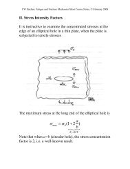
J W Eischen, Fatigue <strong>and</strong> Fracture Mechanics Short Course Notes, © February 2008II. Stress Intensity FactorsIt is instructive to examine the co<strong>nc</strong>entrated stresses at theedge of an elliptical hole in a thin plate, when the plate issubjected to tensile stressesThe maximum stress at the long end of the elliptical hole isσa= σ (1+2 ) bmax 0K t= SCFNote that when a=b (circular hole), the stress co<strong>nc</strong>entrationfactor is 3, i.e. a well-known result.
J W Eischen, Fatigue <strong>and</strong> Fracture Mechanics Short Course Notes, © February 2008The radius of curvature at the end of the major axis isρ =2ba⇒ K = 1+2Thus, as ρ →0, K t →∞ <strong>and</strong> σ max →∞. This marks thetransition from a smooth defect to a sharp crack.tThe formal definition of the stress intensity factor is:aρK ≡ lim σ ( r,0) 2πrI r→0yy• The SIF depends on the intensity of the stress near thecrack tip. It will depend only on the geometry <strong>and</strong>loading (material also if a composite)
J W Eischen, Fatigue <strong>and</strong> Fracture Mechanics Short Course Notes, © February 20081.) Stress Analysis of Cracks H<strong>and</strong>book• Center-cracked plate• Double-edge crack plate• Single edge crack plate• Edge-cracked beam• Edge-cracked simply supported beam• Cracks emanating from a thru-holes in a plate• Crack emanating from an elliptical notch• Buried penny-shaped crack• Edge-cracked solid shaft• Semi-elliptical surface crack• Circumferentially cracked thin-walled pressure vessel• Longitudinally cracked thin-walled pressure vessel
18 of 109
19 of 109
20 of 109
21 of 109
22 of 109
23 of 109
24 of 109
25 of 109
26 of 109
27 of 109
28 of 109
29 of 109
30 of 109
31 of 109
32 of 109
33 of 109
34 of 109
35 of 109
J W Eischen, Fatigue <strong>and</strong> Fracture Mechanics Short Course Notes, © February 20082.) Practical applicationsDesign of a high strength steel pressure vessel-Data: p 0 =5000psi, D=2R=30in, t>0.5in, γ steel =489lb/ft 3σ ys K Ic $/lbA 260ksi 80ksi-in 1/2 $1.40B 220 110 1.40C 180 140 1.00D 180 220 1.20E 140 260 0.50F 110 170 0.15Problem: Design for satisfactory performa<strong>nc</strong>e (SF=2),minimum cost <strong>and</strong> weight are also important
J W Eischen, Fatigue <strong>and</strong> Fracture Mechanics Short Course Notes, © February 2008Stress based design:σσmaxmaxminallowhoopσysσallow=2pR σ0 ys=t 2t= σ= σ =pDpR0t5000(30) 150,0000⇒min= = =σys σys σysσ allow t min Cost-$/ft Weight-lb/ftA 130ksi 0.58in 255$/ft 182lb/ftB 110 0.68 298 213C 90 0.83 258 258D 90 0.83 310 258E 70 1.07 165 330F 55 1.36 62 416
J W Eischen, Fatigue <strong>and</strong> Fracture Mechanics Short Course Notes, © February 2008Fracture <strong>mechanics</strong> based design:The leak-before-break (LBB) failure mode assumes a thruwallcrack with length equal to twice the wall thickness.This crack is designed to leak before causing a failure by<strong>fracture</strong>KIcKI=2pR0πttminminK=20⇒ tmin= =⎜ K ⎟IcIc2 2⎛ pD π ⎞ ⎛265,868⎞⎜ ⎟ ⎜ ⎟⎝ ⎠ ⎝ KIc⎠
J W Eischen, Fatigue <strong>and</strong> Fracture Mechanics Short Course Notes, © February 2008Κ Ιc /2 t min Cost-$/ft Weight-lb/ftA 40ksi-in 1/2 11.04in 3126 $/ft 2233 lb/ftB 55 5.84 2107 1505C 70 3.61 1016 1016D 110 1.46 533 444E 130 1.05 162 324F 85 2.45 108 720
J W Eischen, Fatigue <strong>and</strong> Fracture Mechanics Short Course Notes, © February 2008Hot Isostatic Press failure-HIP Specs:• Pressure= 15,000psi• Temperature=2400F• Up to 24hr process times• Q&T steel, σ uts =185ksi, σ ys =165ksi• OD=97in, ID=76in, L=14ft (huge!)• Failed at cycle 1898, 507 cycles after change i<strong>nc</strong>ooling jacket
J W Eischen, Fatigue <strong>and</strong> Fracture Mechanics Short Course Notes, © February 2008Failure Analysis• Failed pieces reassembled- crack map points tomultiple origin sites, prese<strong>nc</strong>e of corrosion pits onvessel OD• Final <strong>fracture</strong> origin sites indicate semi-circularsurface flaws in the r-θ plane on vessel OD neardiameter transition• Possible temper embrittlement of steel during heattreatment at manufacture• Problems with water treatment chemistry
J W Eischen, Fatigue <strong>and</strong> Fracture Mechanics Short Course Notes, © February 2008Stress Analysis:• Force on lid:F = pπr = 68,000,000lbs• Axial stress (due to pressure only):2i2σ = prizz23,700 psi2 2r − r=• Axial stress (thermal, 300F ΔT):oiσzzEαΔT=± =+ 42,000 psi (OD)2(1 −υ)• Total stress: σ zz =65,700psi• Stress co<strong>nc</strong>entration at diameter taper neglected sofar, FEA only way to calculate• Co<strong>nc</strong>entrated total stress with FEA σ zz =118,000psi• Various heat flux models yield a range 90,600< σ zz
J W Eischen, Fatigue <strong>and</strong> Fracture Mechanics Short Course Notes, © February 2008Fracture Mechanics Analysis:• Flaw model:rIDOD2aaθ• SIFKI= 1.12σzzπ aQ• Critical crack size measurements 0.857
J W Eischen, Fatigue <strong>and</strong> Fracture Mechanics Short Course Notes, © February 20083.) Numerical Calculation of SIF’s Using Finite ElementAnalysisThe distribution of stress near a sharp crack tip under ModeI (symmetric) loading conditions is:σσσxxyyxyKIθ ⎡ θ 3θ⎤= cos 1 sin sin2πr 2 ⎢−⎣ 2 2 ⎥⎦KIθ ⎡ θ 3θ⎤= cos 1 sin sin2πr 2 ⎢+⎣ 2 2 ⎥⎦KIθ θ 3θ= cos sin cos2πr 2 2 2The definition of the stress intensity factor actually followsfrom these expressionsK ≡ lim σ ( r,0) 2πrI r→0yy
J W Eischen, Fatigue <strong>and</strong> Fracture Mechanics Short Course Notes, © February 2008Thus if we know the distribution of stress ahead of cracktip in a real structure we can obtain an estimate of the SIFby graphing σ yy(,0) r 2 π r vs. r .The SIF is just the intercept of this plot. This is a quick, butnot very accurate way to compute the SIF. Another way todo this with FEA data is to use the crack openingdisplacements behind the crack tip, which are for Mode IwhereuyKIr θ ⎡κ + 1 2 θ ⎤= sin cosG 2π2 ⎢ −2 2⎥⎣⎦κ = 3 −4υ for plane strain (thick plates)3-ν= for plane stress (thin plates)1+ ν
J W Eischen, Fatigue <strong>and</strong> Fracture Mechanics Short Course Notes, © February 2008An alternative definition of the SIF is thenIn this case we would graph2G2πKI ≡ limr→0uy( r, π ) κ + 1 r2G2πuy(,0) rκ + 1 rvs. r . This willtypically yield better results for so-called “displacementbased finite element methods.Yet another more efficient <strong>and</strong> accurate way to use the FEAmethod to calculate SIF’s is to work with the strain energyof the structure, which is defined as:1U = σεij ijdV2∫VolIt turns out the rate of change of the total strain energy Uwith respect to crack length is related to the stress intensityfactorG21 dU KI= J = = (for plane stress)t da E2KI= (for plane strain)2E /(1 −ν)The quantities G <strong>and</strong> J (which happen to be equivalent) arethe strain energy release rate <strong>and</strong> J integral (more later inEPFM), respectively. In practice, this requires the solutionof two FEA problems, with slightly differing crack lengths,then
J W Eischen, Fatigue <strong>and</strong> Fracture Mechanics Short Course Notes, © February 20081dU 1 U ( a + Δa) −U ( a)=t da t Δa<strong>and</strong>KI=EG
J W Eischen, Fatigue <strong>and</strong> Fracture Mechanics Short Course Notes, © February 2008The following example, a finite width center-cracked panel,has been solved using the FEA method.The refere<strong>nc</strong>e SIF for this problem is based on Isida (1971),International Journal of Fracture, Vol. 7, No.3 , pp. 301-316. This solution i<strong>nc</strong>ludes a finite height, as well as afinite width correction.
J W Eischen, Fatigue <strong>and</strong> Fracture Mechanics Short Course Notes, © February 2008FEA results:KI=0.306
J W Eischen, Fatigue <strong>and</strong> Fracture Mechanics Short Course Notes, © February 2008Stress <strong>and</strong> Displacement Extrapolation:Stress Extrapolation0.40.35y = 0.0604x + 0.2978K I0.30.250.20 0.2 0.4 0.6 0.8rDisplacement Extrapolation0.40.35y = -0.0959x + 0.3498K I0.30.250.20 0.2 0.4 0.6 0.8 1r
J W Eischen, Fatigue <strong>and</strong> Fracture Mechanics Short Course Notes, © February 2008Strain Energy Method:a U(a) 2ΔU/tΔa * K I2 0.162019 - -2.01 0.162483 0.0928 0.3192.1 0.166906 0.0977 0.328*- factor of 2 due to symmetry, account for material belowthe modeled area for the right crack tip
J W Eischen, Fatigue <strong>and</strong> Fracture Mechanics Short Course Notes, © February 20084.) Co<strong>nc</strong>ept of Influe<strong>nc</strong>e Fu<strong>nc</strong>tionsThe following configuration doesn’t have direct practicalimport, but can be used to develop SIF’s for more complexsituations.KIAP a + ξ, KP a −ξ=IB=πaa− ξ πaa+ξThese are referred to as influe<strong>nc</strong>e fu<strong>nc</strong>tions for the stressintensity factors. If the loads are centered, thenKIA=Pπ a
J W Eischen, Fatigue <strong>and</strong> Fracture Mechanics Short Course Notes, © February 2008Now consider the following problem, a “pressurized crack”KIAa1 a+ ξ σ0dξa+ξ= ∫σ yy( ξ)dξ=aaa πa−ξ∫a πa−ξ−−IFaCarrying out the integration givesKIA= σ0πaWe will now learn why this result is not a surprise. For ageneral non-uniform loading on a center-cracked panel, asshown in the figure below, it turns out the stress intensityfactor can be determined from the related probleminvolving pressure loading (non-uniform in this case)
J W Eischen, Fatigue <strong>and</strong> Fracture Mechanics Short Course Notes, © February 2008That is, for any general far field loading,KIA=a∫−aσyy( xdx ) a+xπ a a−x• This integral applies only for the center-cracked panelgeometry• Every other geometry <strong>and</strong> loading configurationrequires a different influe<strong>nc</strong>e fu<strong>nc</strong>tionThis method of calculating SIF’s is often referred to as theinflue<strong>nc</strong>e fu<strong>nc</strong>tion (IF) method. It depends on having a SIFsolution for point loads on the crack surfaces for a
J W Eischen, Fatigue <strong>and</strong> Fracture Mechanics Short Course Notes, © February 2008particular structural configuration. Another example is theedge-crack geometryThe IF fu<strong>nc</strong>tion for this case is2Pc aKI= F( , )π a a bcc3.52(1 − ) 4.35 −5.28F = a − a +3/2 1/2(1 −a/ b) (1 −a/ b)⎧ c 3/2⎫⎪1.30 − 0.30( )ac⎪⎧ c a⎫⎨ + 0.83 −1.76 ⎬⎨1 −(1 − ) ⎬2⎪ 1 − ( a/ b)a⎪⎩a b⎭⎩⎭
J W Eischen, Fatigue <strong>and</strong> Fracture Mechanics Short Course Notes, © February 2008Then for uniform loading on the edges of a finite widthedge cracked plate,aσ0c aKI= ∫ F dc=σ0πaa b0 π aa( , ) 1.12 if is very smallbGeneral purpose <strong>fracture</strong> <strong>mechanics</strong> software is often basedon the IF method in order to treat general loadings onstructures. All that is required is the stress distribution onthe un-cracked structure.Exponent I<strong>nc</strong>. NASCRAC software:http://www.exponent.com/about/nascrac.htmlwww.exponent.com/about/products/geolib.htmStructural Integrity Associates I<strong>nc</strong>. pc-CRACK software:http://www.structint.com/products/pc-crack/pccrack.html
J W Eischen, Fatigue <strong>and</strong> Fracture Mechanics Short Course Notes, © February 20085.) Modes of FractureWe have discussed what has been referred to as Mode I<strong>fracture</strong>, where the loading is symmetrical about the crackplane <strong>and</strong> tends to only open the crack surfaces. It is alsopossible to have loading that leads to the other “modes”shown below. In most practical applications, the crack willtend to develop <strong>and</strong> orient itself so there is only Mode Ideformation; he<strong>nc</strong>e what we have learned is appropriate formost situationsMode I Mode II Mode IIIOpening Sliding Tearing
J W Eischen, Fatigue <strong>and</strong> Fracture Mechanics Short Course Notes, © February 2008III. Fracture Toughness Testing <strong>and</strong> FractographyThe <strong>fracture</strong> toughness, K Ic , of a given material must bedetermined experimentally, i.e. it is a material property.The <strong>fracture</strong> toughness test is designed so that there isminimal yielding of the material near the crack tip duringthe test, ensuring Linear Elastic conditions. Therefore,before delving into the details of the test, we mustunderst<strong>and</strong> plasticity effects.1.) Plastic Zone EffectsThe so-called Irwin estimate of the plastic zone size, r y , issimply obtained by setting the normal stress on the crackplane equal to the yield strength.KI2πry= σys1 ⎛ K ⎞I⇒ ry= 2π⎜σ ⎟⎝ ys ⎠2(based on elastic stresses- ad hoc)
J W Eischen, Fatigue <strong>and</strong> Fracture Mechanics Short Course Notes, © February 2008A more elaborate analysis, i<strong>nc</strong>luding the effect of plasticityresults in an estimate of the plastic zone size twice thisvalueIrwin proposed the co<strong>nc</strong>ept of an effective crack length toaccount for plastic effects, i.e.a = a+reffy
J W Eischen, Fatigue <strong>and</strong> Fracture Mechanics Short Course Notes, © February 2008KI⎛1 ⎛ K ⎞I= σ0π⎜a+ ⎜ 2π⎜σ⎟⎝ ys⎝⎠2⎞⎟⎟⎠solve for K IKI=σ0πa1 ⎛ σ ⎞01− 2 ⎜σ ⎟⎝ ys ⎠2The denominator is referred to as the plastic zonecorrection factor.
J W Eischen, Fatigue <strong>and</strong> Fracture Mechanics Short Course Notes, © February 20082.) Plane Strain Fracture Toughness Test, J Ic Integral TestThe American Society for Testing <strong>and</strong> Materials has putforward st<strong>and</strong>ards for measuring K Ic (<strong>and</strong> J Ic ). Someremarks on the E399-06 (following page)• Possible test specimens are compact tension, 3pt bend,<strong>and</strong> arc• Specimen dimensions are given in the st<strong>and</strong>ard (toensure minimal r y )• Test specimen is loaded to failure while monitoringforce <strong>and</strong> crack opening displacement• Size requirements are often restrictive, for A533Bpressure vessel steel the required thickness is 30in ormore!• Invalid tests with insufficient thickness may containuseful information
J W Eischen, Fatigue <strong>and</strong> Fracture Mechanics Short Course Notes, © February 2008
J W Eischen, Fatigue <strong>and</strong> Fracture Mechanics Short Course Notes, © February 2008
J W Eischen, Fatigue <strong>and</strong> Fracture Mechanics Short Course Notes, © February 2008
J W Eischen, Fatigue <strong>and</strong> Fracture Mechanics Short Course Notes, © February 20083.) ASM Fractography Tutorial
T • U • T • O • R • I • A • LFractography of Metals <strong>and</strong> Plastics(continued)by Ronald J. Parrington, P.E.Fractography of Metals <strong>and</strong> PlasticsFractography is critical to failure analysis of metals <strong>and</strong> plastics. Fractography of plastics is a relativelynew field withmany similarities tometals. Using case histories,various aspects of failure analysis<strong>and</strong> fractography of metals <strong>and</strong>plastics are compared <strong>and</strong>contrasted.Failure modes common toboth metals <strong>and</strong> plastics i<strong>nc</strong>ludeductile overload, brittle <strong>fracture</strong>,impact, <strong>and</strong> <strong>fatigue</strong>. Analogiescan also be drawn betweenstress-corrosion cracking (SCC)of metals <strong>and</strong> stress cracking ofpolymers. Other metal/plasticfailure analogies i<strong>nc</strong>lude corrosion/chemicalaging, dealloying/scission, residual stress/frozen-instress, <strong>and</strong> welds/knit lines. Stress raisers, microstructure, material defects, <strong>and</strong> thermomechanical historyplay important roles in both types of materials. The key fractographic features for metals <strong>and</strong> plasticsare described in this paper.Historical PerspectivePlastics have been in existe<strong>nc</strong>e forapproximately 130 years. John Hyattpatented nitrocellulose, the firstcommercial plastic, in 1869. However,full-scale development <strong>and</strong> use ofplastics is only approximately 50 yearsold. In contrast, metals have been inuse for hundreds of years.The application of engineering materialsis unavoidably accompanied bythe occurre<strong>nc</strong>e of failures, many ofwhich have been catastrophic. Theconseque<strong>nc</strong>es of material failures, i<strong>nc</strong>ludingdeaths, fina<strong>nc</strong>ial losses, <strong>and</strong>legal ramifications, have e<strong>nc</strong>ouragedthe development of effective failureanalysis methods. Although the costof failure analysis may exceed thevalue of the part, the cost of servicefailures usually far exceeds the costof failure analysis. Many of the techniquesused over the years for the evaluationof metals have been successfullyapplied to plastics, with onlyminor modifications.Fractography is arguably the mostvaluable tool available to the failureanalyst. Fractography, a term coinedin 1944 to describe the scie<strong>nc</strong>e of examining<strong>fracture</strong> surfaces, has actuallybeen used for centuries as part of thefield of metallurgy. Even before that,however, Stone Age man possessed aworking knowledge of <strong>fracture</strong>. Archeologicalfindings of lithic implements,weapons, <strong>and</strong> tools shaped fromstone by controlled <strong>fracture</strong> indicatethat prehistoric man knew how to selectrocks with favorable <strong>fracture</strong> behavior,use thermal spalling to detach bedrockfrom the working core, <strong>and</strong> shape stoneby pressure flaking.Fractography, as we know it today,developed in the 16th century as aquality-control practice employed forferrous <strong>and</strong> nonferrous metalworking.De La Pirotechnia, published by VannoccioBiringuccio in 1540, [1] is oneof the first documents to detail fractographictechniques.66 of 10916 Volume 2(5) October 2002Practical Failure Analysis
Invention of the optical microscopein 1600 provided a significant newtool for fractography, yet it was notused extensively by metallurgists untilthe eighteenth century. In 1722, R.A.de Réaumur [2] published a book withengravings that depicted macroscopic<strong>and</strong> microscopic <strong>fracture</strong> surfaces ofiron <strong>and</strong> steel. Interestingly, the categoriesof macroscopic features developedby de Réaumur have remainedessentially u<strong>nc</strong>hanged through thecenturies.Partly due to the development ofmetallographic techniques for examiningcross <strong>section</strong>s of metals, interestin microfractography waned duringthe nineteenth century. Metalworkerscontinued to use fractographic techniquesfor quality-assura<strong>nc</strong>e purposes,but, for the most part, researchers <strong>and</strong>publications ignored fractography.Several technological developmentsin the twentieth century revitalizedinterest in fractography. Carl A.Zapffe [3] developed <strong>and</strong> extensivelyused fractographic techniques tostudy the hydrogen embrittlement ofsteels. His work led to the discoveryof techniques for photographing<strong>fracture</strong> surfaces at high magnifications.The first fractographs werepublished by Zapffe in 1943.An even more revolutionary developmentwas the invention of thescanning electron microscope (SEM).The first SEM appeared in 1943.Unlike the transmission electron microscope,which was developed a fewyears earlier, it could be used for <strong>fracture</strong>surface examination. An SEMwith a guaranteed resolution of approximately500 Å became commerciallyavailable in 1965. Comparedwith the optical microscope, the SEMexp<strong>and</strong>s resolution by more than oneorder of magnitude <strong>and</strong> i<strong>nc</strong>reases thedepth of focus by more than twoorders of magnitude. The tools formodern fractography were essentiallyin place before plastics achieved widespreaduse.Failure Analysis OverviewThe general procedure for conductinga sound failure analysis is similarfor metallic <strong>and</strong> nonmetallic materials.The steps i<strong>nc</strong>lude: (1) informationgathering; (2) preliminary, visualexamination; (3) nondestructive testing;(4) characterization of materialproperties through mechanical, chemical,<strong>and</strong> thermal testing; (5) selection,preservation, <strong>and</strong> cleaning of <strong>fracture</strong>surfaces; (6) macroscopic examinationof <strong>fracture</strong> surfaces, secondary cracking,<strong>and</strong> surface condition; (7) microscopicexamination; (8) selection,preparation, <strong>and</strong> examination of cross<strong>section</strong>s; (9) identification of failuremechanisms; (10) stress/<strong>fracture</strong><strong>mechanics</strong> analysis; (11) testing tosimulate failure; <strong>and</strong> (12) data review,formulation of co<strong>nc</strong>lusions, <strong>and</strong> reporting.Although the basic steps of failureanalysis are nearly identical, somediffere<strong>nc</strong>es exist between metals <strong>and</strong>plastics. Nondestructive testing ofmetals i<strong>nc</strong>ludes magnetic-particle,eddy-current, <strong>and</strong> radiographic inspectionmethods that are not generallyapplicable to plastics, forobvious reasons. However,ultrasonic <strong>and</strong> acoustic emissiontechniques find applicationsfor both materials.Similarly, different chemicaltest methods are necessary.Typical test methods formetals are optical emissionspectrometry, inductivelycoupled plasma, <strong>and</strong> combustion.Fourier transform infraredspectroscopy is usedextensively to identify plasticsFig. 1by molecular bonding, <strong>and</strong> thermaltesting, differential scanning calorimetry,<strong>and</strong> thermogravimetric analysisare also very important for polymercharacterization. Energy-dispersive x-ray spectroscopy, used in conju<strong>nc</strong>tionwith the SEM, is a very practical toolfor elemental chemical analysis ofboth metals <strong>and</strong> plastics. Also noteworthyis that different chemical solutionsare required for metals <strong>and</strong> plasticsto clean <strong>and</strong>/or protect <strong>fracture</strong>surfaces <strong>and</strong> to etch cross <strong>section</strong>s toreveal microstructure.Causes of FailureOf <strong>course</strong>, the primary objective ofa materials failure analysis is to determinethe root cause of failure.Whether dealing with metallic ornonmetallic materials, normally, theroot cause can be assigned to one offour categories: design, manufacturing,service, or material. Often, severaladverse conditions contribute to thepart failure. Many of the potentialroot causes of failure are common tometallic <strong>and</strong> nonmetallic materials.Improper materials selection, overlyhigh stresses, <strong>and</strong> stress co<strong>nc</strong>entrationsare examples of design-relatedproblems that can lead to prematurefailure. Materials selection must takeinto account environmental sensitivi-Fracture of a glass-filled polyamide threaded partdue to stress co<strong>nc</strong>entration at the thread root67 of 109Practical Failure Analysis Volume 2(5) October 200217
Fractography of Metals <strong>and</strong> Plastics (continued)ties as well as requisite mechanicalproperties <strong>and</strong> welding/joining characteristics.Stress raisers are frequentlya preferred site for <strong>fracture</strong> origin,Fig. 2Fig. 3Fig. 4Cross <strong>section</strong> showing <strong>fracture</strong> along the knit line ofa perfluoralkoxyethylene-lined impellerCross <strong>section</strong> of a polyacetal hinge that <strong>fracture</strong>d(arrow) through an area of porosityMicrobiologically induced corrosion of a 304 SSTvessel weld, characterized by pitting <strong>and</strong> selectiveleaching (arrow)particularly in <strong>fatigue</strong>. Stress raisersi<strong>nc</strong>lude thread roots (Fig.1), sharpradii of curvature, through holes, <strong>and</strong>surface discontinuities (e.g., gatemarks in molded plastic parts).Similarly, many manufacturing<strong>and</strong> material problemsfound in metals also areobserved or have a corollaryin plastics. Weldments are atrouble-prone area for metals,as are weld lines or knit linesin molded plastics (Fig. 2).High residual stresses canresult from metalforming,heat treatment, welding, <strong>and</strong>machining. Similarly, highfrozen-in stresses in injection-moldedplastic partsoften contribute to failure.Porosity <strong>and</strong> voids are commonto metal castings <strong>and</strong>plastic molded parts (Fig. 3).Pores <strong>and</strong> voids serve asstress raisers <strong>and</strong> reduceload-carrying capability.Other manufacturing- <strong>and</strong>material-related problemsthat may lead to failurei<strong>nc</strong>lude adverse thermomechanicalhistory, poor microstructure,material defects,<strong>and</strong> contamination.Fig. 5Hollowing out of a polyacetal hinge due to acidcatalyzedhydrolysisEnvironmental degradation is oneof the most important service-relatedcauses of failure for metals <strong>and</strong> plastics.Other degradation processes i<strong>nc</strong>ludeexcessive wear, impact, overloading,<strong>and</strong> electrical discharge.Failure MechanismsAnother key objective of failure analysisis to identify the failure mechanism(s).O<strong>nc</strong>e again, some failure modesare identical for metals <strong>and</strong> plastics.These modes i<strong>nc</strong>lude ductile overload,brittle <strong>fracture</strong>, impact, <strong>fatigue</strong>, wear,<strong>and</strong> erosion.Analogies also can be drawn betweenmetals <strong>and</strong> plastics with regardto environmental degradation.Whereas metals corrode by an electrochemicalprocess, plastics arevulnerable to chemical changes fromaging or weathering. Stress-corrosio<strong>nc</strong>racking (SCC), a specific form ofmetallic corrosion, is similar in manyways to stress cracking of plastics.Both result in brittle <strong>fracture</strong> due tothe combined effects of tensile stress<strong>and</strong> a material-specific aggressive environment.Similarly, dealloying orselective leaching in metals (Fig. 4),the preferential removal of oneelement from an alloy by corrosion,is somewhat similar to scission ofpolymers (Fig. 5), aform of aging thatcan cause chemicalchanges by selectivelycutting molecularbonds.Analogies can alsobe drawn betweenmetals <strong>and</strong> anothertype of polymer:rubber. Internal hydrogenin steels canprecipitate <strong>and</strong> causehydrogen damage,which is frequently68 of 10918 Volume 2(5) October 2002Practical Failure Analysis
Fig. 6Fig. 7Fig. 8Hydrogen damage of induction-hardened steelpiston rod displaying fisheyesExplosive decompression <strong>fracture</strong> of rubber O-ring,characterized by fisheye-like patternsBeach <strong>and</strong> radial marks visible on torsional <strong>fatigue</strong><strong>fracture</strong> of a 6 in. diameter 4340 shaftcharacterized by localized brittle areasof high reflectivity, known as flakesor fisheyes, on otherwise ductile <strong>fracture</strong>surfaces (Fig. 6). Similarly, explosivedecompression in rubber O-ringsproduces fisheye-like ovular patternson the <strong>fracture</strong> surfaces (Fig.7). Explosive decompression isthe formation of small rupturesor embolisms when an elastomericseal, saturated with highpressuregas, experie<strong>nc</strong>es anabrupt pressure reduction.This failure mechanism isanalogous to the “bends” thatafflict divers who surface tooquickly.FractographyWhen material failure involvesactual breakage, fractographycan be employed toidentify the <strong>fracture</strong> origin,direction of crack propagation,failure mechanism,material defects, environmentalinteraction, <strong>and</strong> the natureof stresses. Some of the macroscopic<strong>and</strong> microscopicfeatures employed by thefailure analyst to evaluate<strong>fracture</strong> surfaces of metals<strong>and</strong> plastics are describedsubsequently. Note, however,that many of the fractographicfeatures described forplastics are not observable forFig. 9Brittle <strong>fracture</strong> of an epoxy layer displaying amirror zone, rib marks, <strong>and</strong> hacklesreinforced plastics <strong>and</strong> plasticscontaining high filler content.Macroscopically VisibleFractographic FeaturesOn a macroscopic scale, all <strong>fracture</strong>s(metals <strong>and</strong> plastics) fall into one oftwo categories: ductile <strong>and</strong> brittle.Ductile <strong>fracture</strong>s are characterized bymaterial tearing <strong>and</strong> exhibit grossplastic deformation. Brittle <strong>fracture</strong>sdisplay little or no macroscopicallyvisible plastic deformation <strong>and</strong>require less energy to form. Ductile<strong>fracture</strong>s occur as the result of appliedstresses exceeding the material yieldor flow stress. Brittle <strong>fracture</strong>s mayoccur at stress levels below the materialyield stress. In practice, ductile <strong>fracture</strong>soccur due to overloading orunderdesigning <strong>and</strong> are rarely thesubject of a failure analysis. However,the unexpected brittle failure of normallyductile materials is frequentlythe subject of a failure analysis.Many macroscopically visible fractographicfeatures serve to identifythe <strong>fracture</strong> origin(s) <strong>and</strong> direction ofcrack propagation. Fractographic featurescommon to metals <strong>and</strong> plasticsare radial marks <strong>and</strong> chevron patterns.Radial marks (Fig. 8) are lines on a <strong>fracture</strong>surface that radiate outward fromthe origin <strong>and</strong> are formed by the inter<strong>section</strong>of brittle<strong>fracture</strong>s propagatingat different levels.Chevron or herringbonepatterns areactually radial marksresembling nestedletter V’s <strong>and</strong> pointingtoward the origin.Fatigue failures inmetals display beachmarks <strong>and</strong> ratchetmarks that serve to(continued on page 44)69 of 109Practical Failure Analysis Volume 2(5) October 200219
Fractography of Metals <strong>and</strong> Plasticsidentify the origin <strong>and</strong> the failuremode. Beach marks (Fig. 8) are macroscopicallyvisible semielliptical linesrunning perpendicular to the overalldirection of <strong>fatigue</strong> crack propagation<strong>and</strong> marking successive positions ofthe adva<strong>nc</strong>ing crack front. Ratchetmarks are macroscopically visible linesrunning parallel to the overalldirection of crack propagation <strong>and</strong>formed by the inter<strong>section</strong> of <strong>fatigue</strong>cracks propagating from multipleorigins.Brittle <strong>fracture</strong>s in plastics also exhibitcharacteristic features, several ofwhich are macroscopically visible (Fig.9). These features may i<strong>nc</strong>lude a mirrorzone at the origin, a mist region,<strong>and</strong> rib marks. The mirror zone is aflat, featureless regionsurrounding theorigin <strong>and</strong> associatedwith the slow crackgrowthphase of<strong>fracture</strong>. The mistregion is locatedimmediately adjacentto the mirror zone<strong>and</strong> displays a mistyappeara<strong>nc</strong>e. This areais a transition zonefrom slow to fastcrack growth. Ribmarks are semiellipticallines resemblingbeachmarks in metallic<strong>fatigue</strong> <strong>fracture</strong>s.MicroscopicallyVisibleFractographicFeaturesOn a microscopicscale, ductile <strong>fracture</strong>in metals (Fig. 10)displays a dimpledsurface appeara<strong>nc</strong>ecreated by microvoidFig. 10Fig. 11(continued) from page 19)coalesce<strong>nc</strong>e. Ductile <strong>fracture</strong> in plastics(Fig. 11) is characterized by materialstretching related to the fibrillarnature of the polymer response tostress. Although a part may fail ina brittle manner, ductile <strong>fracture</strong>morphology is frequently observedaway from the origin. For example,the final fast <strong>fracture</strong> by ductileoverload produces the shear lip inmany metal failures, even when thecrack originated <strong>and</strong> was propagatedby SCC, <strong>fatigue</strong>, or hydrogen embrittlementprocesses. The extent ofthis overload region is an indicationof the stress level. Generally, the largerthe overload region, the higher thestress level on the failed component.Brittle <strong>fracture</strong> of metallic materialsDimpled appeara<strong>nc</strong>e typical of ductile <strong>fracture</strong> ofmetallic materialsFracture of a polyethylene tensile-test specimenexhibiting material stretchingFig. 12 Brittle <strong>fracture</strong> of an FC-0205 powder metalcontrol rod displaying cleavage facetsFig. 13may result from numerous failuremechanisms, but there are only a fewbasic microfractographic features thatclearly indicate the failure mechanism.These features are cleavage facets(Fig. 12), intergranular facets (Fig.13), <strong>and</strong> striations (Fig. 14). Cleavagefacets form in body-centered cubic(bcc) <strong>and</strong> hexagonal close-packedmetals when the crack path follows awell-defined transgranular crystallographicplane (e.g., the {100} planesin bcc metals). Cleavage is characteristicof transgranular brittle <strong>fracture</strong>.Intergranular <strong>fracture</strong>, recognizableby its “rock c<strong>and</strong>y” appeara<strong>nc</strong>e, occurswhen the crack path follows grainboundaries. Intergranular <strong>fracture</strong> istypical of many forms of SCC, hy-Intergranular <strong>fracture</strong> of an embrittled cast steelpneumatic wre<strong>nc</strong>h70 of 10944 Volume 2(5) October 2002Practical Failure Analysis
Fig. 14Fig. 15Fig. 16Fatigue striations visible on type 302 stainless steelspring <strong>fracture</strong>Fatigue striations emanating from <strong>fracture</strong> origin ofpolycarbonate latch h<strong>and</strong>leSEM micrograph of <strong>fatigue</strong> striations shown inFig.15drogen embrittlement, <strong>and</strong> temperembrittledsteel. Fatigue failures ofmany metals exhibit striations at highmagnifications. (Normally, magnificationsof 500 to 2,500× are required.)Striations are semiellipticallines on a <strong>fatigue</strong> <strong>fracture</strong> surface thatemanate outward from the origin <strong>and</strong>mark the crack-front positionwith each successive stresscycle. The spacing of <strong>fatigue</strong>striations is usually veryuniform <strong>and</strong> can be used tocalculate the crack growthrate, if the cyclic stressfreque<strong>nc</strong>y is known. Striationsare discriminated fromstriation-like artifacts on the<strong>fracture</strong> surface in that true<strong>fatigue</strong> striations never crossor intersect one another.Plastics do not displaycleavage <strong>and</strong> intergranular<strong>fracture</strong>. However, similar tometals, striations are foundon <strong>fatigue</strong> <strong>fracture</strong> surfaces(Fig. 15, 16). Striations inplastics typically are observableat much lower magnifications(50 to 200×). However,local softening <strong>and</strong>melting due to hystereticheating can obliterate <strong>fatigue</strong>striations in less rigid plastics.In addition to mirrorzones, mist regions, <strong>and</strong> ribmarks, which are normallyvisible without the aid of amicroscope, brittle <strong>fracture</strong> ofplastics may display hackles,Wallner lines, <strong>and</strong> conicmarks. Hackles (Fig. 9) aredivergent lines radiatingoutward from the <strong>fracture</strong>origin. They are analogous toriver patterns observed on thecleavage facets of transgranularbrittle <strong>fracture</strong>s ofmetals. Wallner lines arefaint, striation-like markingsformed by the interaction ofstress waves reflected fromphysical boundaries with the adva<strong>nc</strong>ingcrack front. Conic marks areparabolic-shaped lines pointing backtoward the origin. Hackles <strong>and</strong>Wallner lines may or may not be visiblewithout the aid of a microscope.Closing RemarksFractographic techniques, developed<strong>and</strong> applied to metal failures forcenturies, have been readily adaptedto the <strong>fracture</strong> analysis of plasticssi<strong>nc</strong>e their emerge<strong>nc</strong>e as a key engineeringmaterial over the last 50 years.However, more work remains to bedone to adva<strong>nc</strong>e fractography ofplastics. One notable area for researchis <strong>fracture</strong> analysis of composites,reinforced plastics, <strong>and</strong> plastics containinghigh filler content. Fracturesof these materials too often aredismissed as inherently lackingmeaningful fractographic features.Finally, there is a definite need for anauthoritative publication on <strong>fracture</strong>in plastics.AcknowledgmentsThe author gratefully acknowledgesthe contributions of Dave Christie<strong>and</strong> Steve Ruoff of IMR Test Labs.Refere<strong>nc</strong>es1. V. Biringuccio: De La Pirotechnia, Venice,1540; see translation by C.S. Smith <strong>and</strong>M.T. Gnudi: The ‘Pirotechnia’ of VannoccioBiringuccio, American Institute of Mining,Metallurgical <strong>and</strong> Petroleum Engineers,New York, 1942.2. R.A. de Réaumur: L’Art de Convertir le FerForgé en Acier, et L’Art d’Adocir le Fer Fondu,(in Fre<strong>nc</strong>h), Michel Brunet, Paris, 1722;see translation by A.G. Sisco: Réaumur’sMemoirs on Steel <strong>and</strong> Iron, University ofChicago Press, 1956.3. C.A. Zapffe <strong>and</strong> G.A. Moore: Trans.AIME, 1943, 154, pp. 335-59.Selected Refere<strong>nc</strong>es• W. Brostow <strong>and</strong> R.D. Corneliussen: Failureof Plastics, Hanser Publishers, Munich, 1986.71 of 109Practical Failure Analysis Volume 2(5) October 200245
Fractography of Metals <strong>and</strong> Plastics (continued)• T.J. Davies <strong>and</strong> I. Brough: “General Practicein Failure Analysis,” Metals H<strong>and</strong>book (9 thed.), vol. 11, Failure Analysis <strong>and</strong> Prevention,American Society for Metals, Metals Park,OH, 1986.• M. Ezrin: Plastics Failure Guide: Cause <strong>and</strong>Prevention, Hanser Publishers, New York,1996.• F.R. Larson <strong>and</strong> F.L Carr: “How FailuresOccur…Topography of Fracture Surfaces,”Source Book in Failure Analysis, AmericanSociety for Metals, Metals Park, OH, 1974.• Metals H<strong>and</strong>book (8 th ed.), vol. 9, Fractography<strong>and</strong> Atlas of Fractographs, AmericanSociety for Metals, Metals Park, OH, 1974.• U. Portugall <strong>and</strong> K. Steinlein: Prac. Metallography,1999, 36(8), pp. 446-62.Credit InfoRonald J. Parrington, IMR Test Labs, 131Woodsedge Drive, Lansing, NY 14882. Contacte-mail: ron@imrtest.com.Failure Analysis Resources from ASM InternationalASM H<strong>and</strong>books in print <strong>and</strong> CD-ROMVolume 19: Fatigue <strong>and</strong> Fracture1996 • 1,057 pages• ISBN: 0-87170-385-8 • ASM PublicationThis volume contains the essential data necessary for you to makeinformed decisions on alloy design <strong>and</strong> material selection to control<strong>fatigue</strong> <strong>and</strong> <strong>fracture</strong>. This H<strong>and</strong>book is especially useful in evaluatingtest data <strong>and</strong> helping you underst<strong>and</strong> the key variables that affectresults.Sections i<strong>nc</strong>lude: Fatigue Mechanisms, Crack Growth, Testing,Engineering Aspects of Fatigue Life, Fracture Mechanics ofEngineering Materials, Fatigue <strong>and</strong> Fracture Control, Castings,Weldments, Wrought Steels, Aluminum Alloys, Titanium Alloys <strong>and</strong>Superalloys, Other Structural Alloys, Solders, Adva<strong>nc</strong>ed Materials.Appendices contain coverage of <strong>fatigue</strong> strength parameters <strong>and</strong> stressintensityfactors.Order #06197G-RPADPFAJPrice: $198.00 ASM Member $159.00Volume 11: Failure Analysis <strong>and</strong> Prevention1986 • 843 pages • ISBN: 0-87170-017-4 • ASM PublicationProvides coverage of every aspect of this critical field–from areview of the engineering aspects of failure analysis to the major typesof failures to in-depth analyses of failures of specific components <strong>and</strong>assemblies. Also i<strong>nc</strong>luded are failure analysis of composites, ceramics,polymers, <strong>and</strong> integrated circuits. Detailed case histories guide youthrough the investigative procedures used <strong>and</strong> the corrective measuresimplemented.Sections i<strong>nc</strong>lude: Engineering Aspects of Failure <strong>and</strong> Failure Analysis,Failure Mechanisms <strong>and</strong> Related Environmental Factors, Products ofPri<strong>nc</strong>ipal Metalworking Processes, Manufactured Components <strong>and</strong>Assemblies, Engineered <strong>and</strong> Electronic Materials.Order #06366G-RPADPFAJPrice: $198.00 ASM Member $159.00Volume 12: Fractography1987 • 517 pages • ISBN: 0-87170-018-2 • ASM PublicationProvides engineers with enha<strong>nc</strong>ed capability for recognizing <strong>and</strong>interpreting the various features of a <strong>fracture</strong>, enabling you to performimproved failure analyses <strong>and</strong> to better determine the relationship ofthe <strong>fracture</strong> mode to the microstructure. The Atlas of Fractographscontains more than 1,300 fractographs invaluable for your underst<strong>and</strong>ingof the causes <strong>and</strong> mechanisms of the <strong>fracture</strong> of engineering materials.Sections i<strong>nc</strong>lude: History of Fractography, Modes of Fracture, Preparation<strong>and</strong> Preservation of Fracture Specimens, Photography ofFractured Parts <strong>and</strong> Fracture Surfaces, Visual Examination <strong>and</strong> LightMicroscopy, Scanning Electron Microscopy, Transmission ElectronMicroscopy, Quantitative Fractography, Fractal Analysis of FractureSurfaces.Order #06365G-RPADPFAJPrice: $198.00 ASM Member $159.0072 of 10946 Volume 2(5) October 2002Practical Failure Analysis
J W Eischen, Fatigue <strong>and</strong> Fracture Mechanics Short Course Notes, © February 2008IV. Fatigue1.) Fatigue crack initiation• Total <strong>fatigue</strong> life is composed of two parts- initiation<strong>and</strong> propagation- N = Ni + Np• We are focusing on propagation- how far <strong>and</strong> at whatrate an existing crack goes• The number of cycles to failure is Nf= Ni+ Np• Initiation life is typical based on the stress range (orrange of strain when the stress level is near or aboveyield level)Δ σ = σ −σmaxmaxmin1σmean = ( σmax + σmin)2σminR =σ
!!!J W Eischen, Fatigue <strong>and</strong> Fracture Mechanics Short Course Notes, © February 2008• Material, surface prep, environment, residual stress,temperature, stress co<strong>nc</strong>entration all effect theseresults• Flat part of the curve is usually at 10 6 -10 8 cycles• Endura<strong>nc</strong>e limitσe≡ maximum stress level at R =−1 below whichcrack initiation is absent• For steels, the ratio of the endura<strong>nc</strong>e limit to theultimate strength is about ½.• The stress that is used in the S-N curve must be theco<strong>nc</strong>entrated stressσ max= K σ tSCF−notK Inomnominal stress
J W Eischen, Fatigue <strong>and</strong> Fracture Mechanics Short Course Notes, © February 2008
J W Eischen, Fatigue <strong>and</strong> Fracture Mechanics Short Course Notes, © February 20082.) Fatigue crack growth rate modelsWe know that for a general cracked structure with anapplied load PK I= f ( a,geometry)PCrack Propagation Mechanisms1.) Brittle <strong>fracture</strong> K I> K Ic⇒ unstable crack growth2.) Slow stable crack growth due to time varying loadswhen K < KIIc
J W Eischen, Fatigue <strong>and</strong> Fracture Mechanics Short Course Notes, © February 2008As P varies in a cyclic manner the crack length mayi<strong>nc</strong>rease in a stable manner. If we know P max , P min , we alsocan calculate K max , K min , ΔK I , K mean . For many materials thecrack growth is observed to depend on ΔK I <strong>and</strong> K mean . Thatis, for each loading cycleΔ a = f ( ΔK I, Kmean)The most common way to express the crack growth “rate”isdadN=f ( ΔKI, Kmean)determined experimentally
J W Eischen, Fatigue <strong>and</strong> Fracture Mechanics Short Course Notes, © February 2008Typical resultsThe straight line portion of the data is usually fit to theParis Lawda= C( ΔK ) nIdNRemarks:• Does not account for threshold, mean stress, oracceleration effects, which are important• For A36 structural steelda10 33.6 10 ( KI) in / cycledN= × − Δ ksiin
J W Eischen, Fatigue <strong>and</strong> Fracture Mechanics Short Course Notes, © February 2008
J W Eischen, Fatigue <strong>and</strong> Fracture Mechanics Short Course Notes, © February 2008Example- edge cracked stripProblem: Given an initial flaw size, a 0 , predict the numberof cycles to grow the crack to a length a fΔKda= C(1.12Δσπa)dNThis equation can then be integrated∫I= 1.12Δσπada N= C(1.12σ )n / 2a∫ Δ0a f n n / 2πa0The result is1−n/ 2 1−n/ 2af− a0N =(1 − n / 2) C(1.12Δσ)Data: for (PMMA)nnπdNn / 2C=2.4x10 -24 , n=6.64, a 0 =0.010in, Δσ=4000psi,K Ic =1000psi-in 1/2
J W Eischen, Fatigue <strong>and</strong> Fracture Mechanics Short Course Notes, © February 2008What is the critical crack size? (this will be a f )KacIc= 1.12σmaxπa1 ⎛ KIc⎞= 0.016inπ⎜ =1.12σ⎟⎝ ⎠2Then to grow the crack from 0.01in to 0.016 in is N=66cycles. The following table shows the effect of changingthe magnitude of the alternating stress.Δσ (psi) N (cycles)6000 4.55000 15.14000 663000 4482000 66111000 660,000500 65,000,000Note the very strong depende<strong>nc</strong>e on the alternating stresslevel. This is typical in <strong>fatigue</strong>. It means accurate stresslevels are needed as input for predictions of lifeMean Stress EffectsThe Paris law does not i<strong>nc</strong>lude the effect of mean stress, forexample the following two stress spectrums would result inthe same crack growth rate,
J W Eischen, Fatigue <strong>and</strong> Fracture Mechanics Short Course Notes, © February 2008It is reasonable to expect more rapid crack growth for thecase when R=0.67.Walker’s lawnda C( ΔKI)= for -1 ≤ R < 1mdN (1 − R)• accelerates crack growth for high R ratiosForman’s law( ΔK)nda CI= for -1 ≤ R < 1dN (1 −R)K −Δ KIc• accelerates crack growth for high R ratios <strong>and</strong> asK I →K Ic• threshold effects are not i<strong>nc</strong>luded• mean stress effects are usually importantI
J W Eischen, Fatigue <strong>and</strong> Fracture Mechanics Short Course Notes, © February 2008Variable Amplitude Loading:So far we have addressed constant amplitude loading. Morerealistic stress spectrums would appear as followsThe methodology for predicting crack growth due to aspectrum like this would be to break it down into a series ofconstant amplitude “transients”
J W Eischen, Fatigue <strong>and</strong> Fracture Mechanics Short Course Notes, © February 2008Boeing Wing Skin Fatigue Example:• We have strain-gage data (converted to stress) for alocation near a rivet hole on the underside of the wing• We will assume the initial flaw size is 1/8 in.• We will estimate the number of flights to failure( K ) 2.2−6da 3× 10 ΔI=dN (1 −R)K −ΔKKIc= 70ksi inIcIin/cycleWe can use case 19.1 from the SACH for the SIF.⎛ a ⎞KI= σnomπaF0 ⎜ ⎟=1.45σnomπa⎝R+a⎠Δ K = 1.45ΔσπaInomIn order to proceed, make the strong assumption that da/dNin the first flight remains constant in all future flights(discuss implications of this)Δ K = 1.45 Δ σ π(0.125) = 0.91ΔσInomnomAccumulate da/dN for each transient during a typical flightΔ a =−63 10 0.91( σ ) 2.2× Δnom(1 −R)(70) −0.91ΔσnomN
J W Eischen, Fatigue <strong>and</strong> Fracture Mechanics Short Course Notes, © February 2008
J W Eischen, Fatigue <strong>and</strong> Fracture Mechanics Short Course Notes, © February 2008Transient σ max σ min Δσ nom R N ΔK I ΔaT-off/l<strong>and</strong> 46 0 46 0 1 42 3.94x10 -4Climb 15 o 46 20 26 0.44 2 24 4.06Climb/cruise 40 24 16 0.6 3 15 2.43Cruise 36 24 12 0.67 17 11 7.99Descent 42 18 24 0.43 3 22 4.41Transition 44 18 26 0.41 1 24 1.79Approach 44 28 16 0.64 2 15 2.04Total: 0.0027inThis is the i<strong>nc</strong>rease in crack length in the first flight. Tocalculate the total number of flights to failure, we need thecritical crack size21 ⎛ K Ic⎞ 1cr= ⎜ ⎟ 2π σmax F0a⎝where σmax⎠= 46ksiIt is necessary to iterate to find the critical crack sizebecause F 0 depends on a.a cr F 00.35 (guess) 1.20.5 1.10.61 1.080.63 close enough
J W Eischen, Fatigue <strong>and</strong> Fracture Mechanics Short Course Notes, © February 2008The number of flights to failure is thenN f0.63in − 0.125in= = 187flights0.0027in/flight• This is not conservative because it does not take intoaccount an i<strong>nc</strong>reasing K I as a i<strong>nc</strong>reases.• Updating the SIF after each flight only gives N f =60flights• Updating the SIF after each transient only gives N f =59flights
J W Eischen, Fatigue <strong>and</strong> Fracture Mechanics Short Course Notes, © February 2008HIP Failure Fatigue Example:• Why did the vessel fail in 1898 cycles or 507 cyclesafter wet-wall cooling was installed?• Fatigue crack propagation governed by da/dN=C(ΔK I ) n• Integrate backwards from a cr , predict a i consistent witha given number of cycles• Results:• Air environment: a i =0.446-0.776in for 1898cycles• Hot water corrosive environment: a i =0.042-0.081in for 507 cycles (consistent with observedpit sizes)
J W Eischen, Fatigue <strong>and</strong> Fracture Mechanics Short Course Notes, © February 20083.) Effect of overloads, retardation modelsProblematic load seque<strong>nc</strong>e:• Tension overloads (shown) tend to produce retardationof crack growth or crack arrest. Tensile overloadsleave compressive residual stress ahead of the cracktip• Compressive overloads have the opposite effect, i.e.acceleration of crack growthThere are several models for the retardation effect; one ofthe popular ones is Wheeler’s (Trans. ASME J. BasicEngr., Vol. 94, 1972) model.
J W Eischen, Fatigue <strong>and</strong> Fracture Mechanics Short Course Notes, © February 2008wherea0dyaidy=crack length when overload occurs0= plastic zone induced by overload (Irwin calc)= instantaneous crack length after overload (varies)i= plastic zone induced cyclic stresses following overload (Irwin calc)δ = dista<strong>nc</strong>e from instantaneous crack tip to edge of overload plastic zoneThe crack growth rate law while the crack tip is imbeddedin the overload plastic zone is⎛ da ⎞ ⎛dy i⎞ ⎛ da ⎞⎜ ⎟ = ⎜ ⎟ ⎜ ⎟⎝dN⎠retarded⎝ δ ⎠ ⎝dN⎠mFor high strength steels, m=1.3 <strong>and</strong> for titanium alloysm=3.4.
J W Eischen, Fatigue <strong>and</strong> Fracture Mechanics Short Course Notes, © February 2008Another model is Elber’s (see ASTM STP 486, 1971),which employs the co<strong>nc</strong>ept of an opening stress, σ op , astress level that must be overcome before additional crackgrowth occurs. After an overload, the opening stress isgreater than 0. ThenΔ σ = σmax−σminΔ σeff = σmax − σopempiricalThus, effectively, this acts to reduce ΔK I
J W Eischen, Fatigue <strong>and</strong> Fracture Mechanics Short Course Notes, © February 20084.) Cycle countingThere are several algorithms for converting a variableamplitude load spectrum to a series of constant amplitudetransients. A popular one is called the rainflow method.Assuming we have a series of max-min (peak-valley) pairsin seque<strong>nc</strong>e the rules are:1.) Start water drop from each peak <strong>and</strong> valley insuccession from left to right2.) Flow from a peak will stop if it sees a higher peak thanthe one from it started, similar for deeper valleys3.) Flow will stop to avoid collision with an earlier drop4.) Match up min-max <strong>and</strong> max-min pairs, these are thecycles
J W Eischen, Fatigue <strong>and</strong> Fracture Mechanics Short Course Notes, © February 2008Min-Max Pairs σ max σ min NAH/HA 30 -36 1CB/BC 18 -18 1EF/FE 3 -12 1GD/DG 12 -30 1
J W Eischen, Fatigue <strong>and</strong> Fracture Mechanics Short Course Notes, © February 2008From Fuchs <strong>and</strong> Stephens, Metal Fatigue in Engineering, Wiley, 1980.
J W Eischen, Fatigue <strong>and</strong> Fracture Mechanics Short Course Notes, © February 2008V. Introduction to Elastic Plastic Fracture Mechanics1.) Introduction to Plasticity TheoryLinear Elastic Fracture Mechanics (LEFM) assumes alinear relationship between stress <strong>and</strong> strainCase i.) linear elastic material responseThe are alternative models of nonlinear response
J W Eischen, Fatigue <strong>and</strong> Fracture Mechanics Short Course Notes, © February 2008Case ii.) nonlinear elastic responseCase iii.) Elastic-plastic responsewhereε = total strainEε = elastic strainPε = plastic strain
J W Eischen, Fatigue <strong>and</strong> Fracture Mechanics Short Course Notes, © February 2008Elastic Plastic Fracture Mechanics (EPFM), for the mostpart, is based on Case ii.), assuming the structure is in aloading mode only, no unloading. A Ramberg-Osgoodstress-strain curve is often employed.• α, n, σ ys , <strong>and</strong> ε ys are constants used to fitexperimental stress-strain dataNow we need to have a stress-strain model that accountsfor multiaxial stresses in the vicinity of the crack tip (e.g.σ xx , σ yy , σ xy , etc. Then,
J W Eischen, Fatigue <strong>and</strong> Fracture Mechanics Short Course Notes, © February 2008ε = ε + εijEijPijelasticplasticn−11+ν ν 3 ⎛ σ ⎞ sij= σij − δijσkk+ αεysE E 2 ⎜σ ⎟ ⎝ ys ⎠ σyswheres= σ −δσij ij ij kkσ =3ssij2ij/ 3 (deviatoric stress)(effective stress)The so-called HRR stress distribution at a crack tipassuming nonlinear stress-strain response is⎛n 1J ⎞ +σ ij= σ ij ( θ)⎜αεysσysIr⎟⎝n ⎠1
J W Eischen, Fatigue <strong>and</strong> Fracture Mechanics Short Course Notes, © February 2008
J W Eischen, Fatigue <strong>and</strong> Fracture Mechanics Short Course Notes, © February 2008
J W Eischen, Fatigue <strong>and</strong> Fracture Mechanics Short Course Notes, © February 2008
J W Eischen, Fatigue <strong>and</strong> Fracture Mechanics Short Course Notes, © February 2008Compare with LEFM,σ KI EJ( ) ij= fijfij( )2 rθ =π2πrθEPFM,nn1= 1: σij∼ (same as LEFM)r>> 1: σ ∼ constant (no singularity at all)ijRemark:• No K I in EPFM, the J integral assumes this role.
J W Eischen, Fatigue <strong>and</strong> Fracture Mechanics Short Course Notes, © February 20082.) Practical Applications- use of the Ductile FractureH<strong>and</strong>bookThis h<strong>and</strong>book (three 2in thick 3-ring binders) provides atabulation of EPFM solutions for a wide range of crackconfigurations <strong>and</strong> loadings for commonly e<strong>nc</strong>ounteredgeometry• Compact tension specimen• Center cracked panel• Single edge notched specimen (tension <strong>and</strong>bending)• Double edge notched specimen in tension• Internally pressurized cylinder with an axial crack• Cylinder under tensile load with an internalcircumferential crackFor these cases several quantities of interest are available:limit load P 0 , J integral, crack mouth openingdisplacement, load line displacement, crack tip openingdisplacement
J W Eischen, Fatigue <strong>and</strong> Fracture Mechanics Short Course Notes, © February 2008The failure criterion in EPFM is a two-step one:Onset of crack extensionJ > J = JContinued unstable crack growthIcRdJdadJ>daR
J W Eischen, Fatigue <strong>and</strong> Fracture Mechanics Short Course Notes, © February 2008Example: circumferentially cracked cylinderData: Geometry- R i =90in, R o =99in., b=9in.,2L=180in.(length), a 0 =2.25in.Material- 304SS, E=30x103ksi, ν=0.3, σ ys =30ksi,α=1.69, n=5.42, ε ys =0.001
106 of 109
107 of 109
J W Eischen, Fatigue <strong>and</strong> Fracture Mechanics Short Course Notes, © February 2008Elastic J e :Jewhere2( 1 ν )2I∞ aeRiKI= σ πaeF( , ) F tabulatedb RP = π R −Rye2 2(o i)a = a+φrr1 n −1⎛K ⎞= ⎜ ⎟βπ nI+ 1⎜σ⎟ ⎝ ys ⎠1φ =2⎛ P ⎞1+ ⎜ ⎟⎝Po⎠2P = σ πR −R3wherey2 2o ys o cR = R + ac= −iKEσ∞2oElastic J p :a ⎛J c h⎝Pp= ασysεys 1 ⎜ ⎟b Po⎞⎠n+1
J W Eischen, Fatigue <strong>and</strong> Fracture Mechanics Short Course Notes, © February 2008Total J:eJ = J + JpRemarks:• For σ ∞ =40ksi, crack size would i<strong>nc</strong>rease to 2.4in <strong>and</strong>arrest• For σ ∞ =44ksi, crack would be unstable