7. operating the multipress - Grass
7. operating the multipress - Grass
7. operating the multipress - Grass

You also want an ePaper? Increase the reach of your titles
YUMPU automatically turns print PDFs into web optimized ePapers that Google loves.
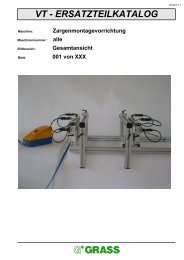
<strong>7.</strong> OPERATING THE MULTIPRESS7-5 Setting <strong>the</strong> Multipress - General information7-501 Setting <strong>the</strong> side stops Illustration 7-501-01Tools required: 5 mm Allen keyLoosen <strong>the</strong> screw “1” with <strong>the</strong> 5 mm Allen key “2” by turning counterclockwise. Slide <strong>the</strong> stop “3” to <strong>the</strong>desired size. The side with <strong>the</strong> measurements marked “3” is <strong>the</strong> side with <strong>the</strong> side stops. Tighten <strong>the</strong> screw“1” clockwise.To prevent errors between <strong>the</strong> left and right, we recommend using a stop adjustment gauge as <strong>the</strong> secondside.The stop adjustment gauge and <strong>the</strong> zero-point retainer “4” are included in <strong>the</strong> standard equipment.7-502 Operating <strong>the</strong> stop adjustment gauge Illustrations 7-502-01, 7-502-02, 7-502-03,7-502-04Tools required: 5 mm Allen key- After adjusting <strong>the</strong> side stops “A“ and “B“ for <strong>the</strong> right side, adjust <strong>the</strong> left side. For example, <strong>the</strong> hinges aremounted on <strong>the</strong> left and right doors.- Insert <strong>the</strong> pin “1” (illustration 7-502-01) in <strong>the</strong> bore hole “2” (illustration 7-502-01) in <strong>the</strong> center of <strong>the</strong> zeropoint gauge “3”.- Loose <strong>the</strong> flap screw “4” (illustration 7-307-02). Slide <strong>the</strong> adjustment ring “5” (illustration 7-502-01) against<strong>the</strong> stop catch “6” (illustration 7-502-01) of <strong>the</strong> side stops “B”. Tighten <strong>the</strong> flap screw “4” (illustration7-502-02). Caution: The flap screw must point upward. If necessary, use more adjustment rings “5”.- Press down all stop catches “6”.- Swing <strong>the</strong> adjustment gauge “8” through 180˚ to <strong>the</strong> left side (illustration 7-502-03).- Loosen a stop “C” on <strong>the</strong> left side (illustration 7-502-04). Slide <strong>the</strong> stop “C” against <strong>the</strong> adjustment ringuntil <strong>the</strong> stop catch lines up with <strong>the</strong> adjustment ring. Tighten <strong>the</strong> side stops.- If necessary, use more stops.If <strong>the</strong> same hole patterns are repeated, we recommend getting a stop adjustment gauge for each hole patternand replacing <strong>the</strong> flap screws with set screws. This allows <strong>the</strong> desired hole patterns to be sized exactlyand precisely on both sides at anytime by means of a stop adjustment gauge.The star in your cabinet59