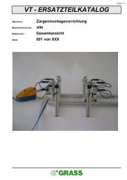
7. operating the multipress - Grass
7. operating the multipress - Grass
7. operating the multipress - Grass

Create successful ePaper yourself
Turn your PDF publications into a flip-book with our unique Google optimized e-Paper software.
<strong>7.</strong> OPERATING THE MULTIPRESS7-304 Setting <strong>the</strong> vertical boring speed Illustration 7-304-01No tools required.The Multipress operates with a continuously adjustable feeding speed and a continuously adjustable<strong>operating</strong> speed.When <strong>the</strong> vertical bore head moves down, <strong>the</strong> pneumatic cylinder releases air by means of <strong>the</strong> throttle “1”and unimpeded by means of <strong>the</strong> activated roller valve (item 12 in <strong>the</strong> pneumatic wiring diagram). The feedingspeed is set with this first throttle “1”. Turning it clockwise decreases <strong>the</strong> feeding speed.The pneumatic valve (see item 12, wiring diagram) is released about 100 mm underneath <strong>the</strong> vertical borehead’s upper end position. In addition, <strong>the</strong> air must now be released by <strong>the</strong> throttle “2”. The <strong>operating</strong> speedis set with this throttle. Turning it clockwise decreases <strong>the</strong> <strong>operating</strong> speed.Throttle “1” corresponds to item 11 in <strong>the</strong> pneumatic wiring diagram.Throttle “2” corresponds to item 13 in <strong>the</strong> pneumatic wiring diagram.The following is generally valid for <strong>the</strong> <strong>operating</strong> speed:The harder <strong>the</strong> workpiece, <strong>the</strong> slower <strong>the</strong> <strong>operating</strong> speed should be; <strong>the</strong> less <strong>the</strong> tool cuts, <strong>the</strong> slower <strong>the</strong><strong>operating</strong> speed should be.The out-going air of <strong>the</strong> vertical cylinder is collected and used to blow out shavings and chips by <strong>the</strong> exhaustarbor in <strong>the</strong> gearbox (see item 24 in <strong>the</strong> pneumatic wiring diagram).The upward movement of <strong>the</strong> vertical bore head is always performed full speed.Illustration 7-304-01- First throttle is to set feeding speed. (See item 11 in pneumatic wiring diagram).- Second throttle is to set <strong>operating</strong> speed. (See item 13 in pneumatic wiring diagram).7-305 Setting <strong>the</strong> vertical travel limits Illustrations 7-305-01 and 7-305-02No tools required.Changeovers or adjustments may only be performed when <strong>the</strong> machine is out of operation.Lift <strong>the</strong> lever “1” up to a parallel position as shown in illustration 7-305-02. The travel limit is activated. During<strong>the</strong> next drilling cycle, <strong>the</strong> bore head can only move up by about 80 mm.Lift <strong>the</strong> lever “1” to a slanted position as shown in illustration 7-305-01. The travel limit is not activated.During <strong>the</strong> next drilling cycle, <strong>the</strong> bore head can move up all <strong>the</strong> way.To activate <strong>the</strong> travel limit:In this position various cabinet fittings cannot be inserted. Pull <strong>the</strong> button knob “2” to <strong>the</strong> right. Move <strong>the</strong>lever “1” behind to <strong>the</strong> parallel position and engage in bore hole “3”.To deactivate <strong>the</strong> travel limit:Pull <strong>the</strong> button knob “2” to <strong>the</strong> right. Move <strong>the</strong> lever “1” to <strong>the</strong> front in <strong>the</strong> slanted position and engage in <strong>the</strong>bore hole “4”.The star in your cabinet55