7. operating the multipress - Grass
7. operating the multipress - Grass
7. operating the multipress - Grass

You also want an ePaper? Increase the reach of your titles
YUMPU automatically turns print PDFs into web optimized ePapers that Google loves.
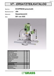
4. DESCRIPTION OF MACHINE COMPONENTS4-004 Description of <strong>the</strong> <strong>operating</strong> features Illustration 4-004-01Multipress Illustration 4-004-011 The selector switch for <strong>the</strong> pneumatic hold-down device is an accessory.left position = workpiece released right position = workpiece clamped2 The start button for <strong>the</strong> vertical movement.As long as <strong>the</strong> start button is pressed down or activated, <strong>the</strong> bore head moves downward until <strong>the</strong> borehead rests on <strong>the</strong> drilling depth stop or until <strong>the</strong> pneumatic cylinder has executed <strong>the</strong> complete strokemotion or until <strong>the</strong> depth gauge activates.3 The selector switch for <strong>the</strong> workpiece is on “clamp” with horizontal drilling.left position = workpiece released right position = workpiece clamped4 The start button for <strong>the</strong> horizontal movement.As long as <strong>the</strong> start button is pressed down or activated, <strong>the</strong> bore head moved towards <strong>the</strong> front until<strong>the</strong> bore head rests on <strong>the</strong> drilling depth stop (revolver stop) or until <strong>the</strong> pneumatic cylinder has executed<strong>the</strong> complete stroke motion.5 The main switch which is located in <strong>the</strong> switchgear cabinet.Warning: this switch controls <strong>the</strong> electric motor only … not <strong>the</strong> pneumatic control6 Insertion die arm which holds <strong>the</strong> insertion dies.7 Drilling depth gauge of <strong>the</strong> vertical bore head8 The travel limit of <strong>the</strong> vertical bore head9 Locking pin to swing <strong>the</strong> vertical bore head10 Revolver stop - travel limit of <strong>the</strong> horizontal bore head11 Manual wheel to adjust distances of <strong>the</strong> vertical bore head12 Revolver stop - various drilling depths of <strong>the</strong> horizontal bore head13 Height adjustment of <strong>the</strong> horizontal bore head4-005 Machine operationsVertical bore head:By pressing <strong>the</strong> start button “2” (see illustration 4-004-01), <strong>the</strong> pneumatic cylinder is activated and guides<strong>the</strong> bore head’s downward movement.The air is released from <strong>the</strong> cylinder by means of a non-return throttle valve “11” (illustration 4-006-0X) and<strong>the</strong> activated pneumatic roller valve “12” (illustration 4-006-0X) or <strong>the</strong> non-return throttle valve “13”(illustration 4-006-0X). The downward motion continues as long as <strong>the</strong> start button is pressed. The processis completed when <strong>the</strong> set depth is reached (position 7, illustration 4-004-01) or when <strong>the</strong> depth gauge hitsan obstruction. If <strong>the</strong> start button is released or <strong>the</strong> depth gauge meets an obstacle, <strong>the</strong> vertical bore headgoes back up.Horizontal bore head:In order for <strong>the</strong> horizontal bore head to work, <strong>the</strong> workpiece must be clamped down with <strong>the</strong> swinging insertiondie arm. The selector switch “3” (illustration 4-004-01) must be turned to <strong>the</strong> right. Activating <strong>the</strong> startbutton “4” (illustration 4-004-01) initiates a movement of <strong>the</strong> horizontal bore head towards <strong>the</strong> front until <strong>the</strong>set drilling depth is reached by means of a revolver stop “12: (illustration 4-004-01). Releasing <strong>the</strong> startbutton makes <strong>the</strong> horizontal bore head move back again.The star in your cabinet37