A Dual-Band Wire Beam for 17 & 12 Meters - KG4JJH
A Dual-Band Wire Beam for 17 & 12 Meters - KG4JJH
A Dual-Band Wire Beam for 17 & 12 Meters - KG4JJH

Create successful ePaper yourself
Turn your PDF publications into a flip-book with our unique Google optimized e-Paper software.
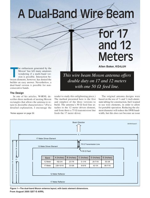
A <strong>Dual</strong>-<strong>Band</strong> <strong>Wire</strong> <strong>Beam</strong><strong>for</strong> <strong>17</strong>and <strong>12</strong><strong>Meters</strong>The enthusiasm generated by theMoxon 1 has left many amateurswondering if a multi-band versionis possible. Interaction betweenelements, however, has denied thebuilder an easy answer. Nevertheless, adual-band version is possible <strong>for</strong> nonconsecutivebands.Allen Baker, <strong>KG4JJH</strong>This wire beam Moxon antenna offersdouble duty on <strong>17</strong> and <strong>12</strong> meterswith one 50 Ω feed line.The DesignIn one of his articles, W4RNL describesthree methods of nesting Moxonrectangles that allows the antenna to retainits desirable characteristics. 2 (For adetailed explanation, I encourage the1Notes appear on page 32.reader to study this enlightening piece.)The method presented here is the firstand simplest of the three versions tobuild. The antenna’s 50 Ω feed line attachesto the <strong>12</strong> meter driven element,and from there a 75 Ω transmission linefeeds the <strong>17</strong> meter driver.The original antenna designs werebased on the use of 3 /4 and 1 /2 inch aluminumtubing <strong>for</strong> construction, but I wantedto use wire elements, in order to allow<strong>for</strong> portable operation. Reducing the elementdiameter will reduce the SWR bandwidth,but this does not become an issueFigure 1—The dual-band Moxon antenna layout, with basic element dimensions.From August 2005 QST © ARRL
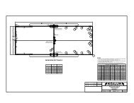
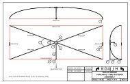
<strong>for</strong> the narrow <strong>12</strong> and <strong>17</strong> meter bands.Numerous EZNEC modeling sessionsyielded a dual-band design that appearedto equal Moxon wire monobander parameters.3 Figure 1 shows the basic antennalayout and Table 1 shows the modeleddata <strong>for</strong> both free-space and 30 foot elevations.Detailed construction drawingsare available at the ARRL Web site. 4The HubTo ensure a rugged and weatherproofdesign, fiberglass spreaders are mountedon an aluminum plate using stainless steelU-bolts. A view of the center hub, togetherwith the top guy anchoring postcan be seen in Figure 2. Two die-cast aluminumflanges secure the mast to the hubon the bottom, and the guy line post onthe top. The hub is made from a one-footsquare of aluminum plate of 0.190 inchthickness. Using a paper template tapedto the aluminum plate, center punch anddrill all holes. Next, cut the plate into acircle to reduce the weight. On the top ofthe plate, draw a 4 inch diameter circle,in the center, with a permanent marker.This circle will be used later to align thespreaders. Four 3 /8-16 × 1 1 /2 inch stainlesssteel hex bolts and stop nuts are usedto attach the flanges to the top and bottomsides of the plate. Figure 3 shows thehub bottom.The SpreadersThe four main spreaders are made of3/4 and 1 /2 inch OD × 1 /8 inch wall fiberglasstubing. A feed line spreader supportsthe coax and transmission line onone side, while a balance spreader providesbalance and element support on theopposite side. A <strong>12</strong> inch piece of 1 /2 inchOD tubing is inserted into one end of each3/4 inch tubing at the hub <strong>for</strong> rein<strong>for</strong>cement.A cutting schedule is shown inTable 2.To keep from drilling holes and weakeningthe spreaders, the wire elementsand guy lines are attached using nyloncollars. 5 These “collars” slide over thefiberglass tubing and tighten with a setscrew.Four 1 /2 inch ID collars are drilledand tapped (opposite the setscrew) to accept1 /4-20 nylon screws which are usedas the <strong>17</strong> meter element corner anchors.Table 1Modeled Antenna DataFour 3 /4 inch ID collars are drilled andtapped (opposite the setscrew) to accept1/4-20 nylon screws, which are used as the<strong>12</strong> meter element corner anchors. Thenylon screws and collars provide a weatherproofmethod of securing the elementswithout adding metal that might affectresonance. The collars also provide aneasy way to adjust the elements. A partialview of the inner element (<strong>12</strong> meter)collars can be seen in Figure 4.The Feed Line/Balance SpreadersTwo type-C, 1 /2 inch PVC conduit bodiesare mounted on the feed line spreaderElevation Free-Space 30 FeetCenter Frequency (MHz) 18.118 24.94 18.118 24.94Gain (dBi) 5.97 5.81 10.94 10.84Front-to-Back Ratio (dB) 27.99 30.64 21.35 25.46Complex Impedance (Ω) 45.1 – j5.3 44.4 + j<strong>12</strong>.9 48.3 – j8.9 41.6 + j<strong>12</strong>.8SWR 1.16:1 1.35:1 1.2:1 1.4:1Table 2Cutting ScheduleDescription Quantity Total Length Materials(Inches)Spreader rein<strong>for</strong>cement 6 <strong>12</strong> 1/2" OD fiberglass tubing*Main spreader extension 4 48 1/2" OD fiberglass tubing*Main spreader 4 96 3/4" OD fiberglass tubing*Feed line spreader 1 48 3/4" OD fiberglass tubing*Balance spreader 1 48 3/4" OD fiberglass tubing*<strong>17</strong> meter driver 2 153 14 gauge Flexweave wire and ringterminals<strong>17</strong> meter reflector 1 325 1 /4 14 gauge Flexweave wire and ringterminals<strong>17</strong> meter insulator 2 10 5 /8 Screen base ( 1 /2" wide)<strong>12</strong> meter driver 2 115 14 gauge Flexweave wire and ringterminals<strong>12</strong> meter reflector 1 235 5 /8 14 gauge Flexweave wire and ringterminals<strong>12</strong> meter insulator 2 6 1 /8 Screen base ( 1 /2" wide)*All fiberglass tubing is 1 /8" wall.Figure 2—A top view of the antennacenter hub during construction, togetherwith the guy anchor post.Figure 3—A bottom viewof the antenna center hub.From August 2005 QST © ARRL
Figure 4—Element and guy anchor collars. The inner (<strong>12</strong> meter)element collars are shown.Figure 5—One of the conduit bodies. These house thetransmission and phasing line junctions to the driven elements.and provide access to the feed line, transmissionline, and driven element terminalposts. The conduit bodies slide over the 3 /4inch tubing and are secured with stainlesssteel setscrews. After you have determinedthe location of each conduit body, cut slots(inside the conduit bodies) on the top ofthe 3 /4 inch fiberglass feed line spreader toallow coax cable entry and exit. Two 3 /4 inchID collars are mounted on the balancespreader <strong>for</strong> element support. Once again,drill and tap both collars (opposite the setscrew)to accept a 1 /4-20 nylon screw. Also,drill and tap two 1 /4-20 holes in the bottomof both conduit bodies <strong>for</strong> the setscrews.Figure 5 shows a close-up of one of theconduit bodies.The ElementsThe elements are cut from 14 gaugeFlexweave wire, according to the cuttingschedule of Table 2. One hundred feet ofwire will provide enough length <strong>for</strong> bothbands. The insulators are made from 1 /2 inchwide strips, cut from screen base (used <strong>for</strong>screened-in porches). The elements are attachedto the insulators and feedpoints bycrimping and soldering ring terminals tothe wire ends—securing them to the insulatorswith #6 thread-cutting screws. Youshould be careful to include the lengths ofthe ring terminals when cutting the wire toget the correct lengths (Figure 6).The Guy LinesNylon collars are drilled and tappedto accept 3 /16 inch stainless steel eyeboltsthat are used <strong>for</strong> the guy line tie points.Four 1 /2 inch ID collars are used <strong>for</strong> thefour main spreaders and two 3 /4 inch IDcollars <strong>for</strong> the feed line and balancespreaders. Using a combination of <strong>for</strong>ces,that are provided by the guy lines and elements,the main spreaders are stressedinto an “S” curve to supply the tensionneeded to stretch the elements taut.Prepare the guy line post by cutting a14 inch piece of 1 1 /4 inch schedule 40 PVCpipe. Measure 2 inches down from the end,From August 2005 QST © ARRLFigure 6—Be sure to include the ring terminals when measuring element length.Figure 7—The guy wire center post, turnbuckles, and hub. Note the conduit boxes atthe lower right. These serve as feed line junctions to the driven elements. The feed lineand phasing line pass through the fiberglass support arm.and drill a 1 /4 inch OD hole all the waythrough the center of the pipe. Next, measure1 5 /8 inches down from the same endand 90° away from the first hole, and drilla 3 /16 inch hole all the way through the centerof the pipe. Install two 1 /4 inch and two3/16 inch stainless steel eyebolts with hexnuts. With the eyebolts on top, secure thepipe into the top hub-mounted flange bytightening the setscrew.Prepare six guy lines using Kevlartwine, fishing swivels, and clips. TheKevlar is stronger than fishing line and itwill not stretch as much as nylon or polyester.The total length <strong>for</strong> the four mainspreader assemblies (Kevlar length plusswivel/clips on each end) should be 96inches. Make the feed line and balancespreader guy line assemblies 46 incheslong. I used standard fishing line knotson each end and, with a little practice, Iwas able to get the lengths correct.Each guy line is attached to an aluminum/stainlesssteel turnbuckle at the guy
line post to make adjustments easier, asshown in Figure 7. The other ends of thelong guy lines attach to the four 1 /2 inchOD collars with eyebolts mounted on themain spreaders, and the short guy linesattach to the two feed line/balancespreader 3 /4 inch OD collars. Figure 8shows a closeup of a typical guy lineanchoring collar, together with an elementsupport collar.AssemblySince I wanted to be able to disassemblethe antenna, I fastened the spreaderstogether with screws and nuts. Inserta 48 inch long piece of 1 /2 inch OD fiberglasstubing into one end of the 3 /4 inchOD × 96 inch long main spreader with a<strong>12</strong> inch overlap. Drill two 9 /64 inch ODholes through both tubes—3 inches fromeach overlapped end—being careful todrill straight through the centerline of thetubes and perpendicular to its surface.Secure using two 6-32 × 1 inch stainlesssteel screws and stop nuts at each overlap,but do not over tighten. Repeat thisprocess <strong>for</strong> all four main spreaders.Spread a thin bead of Liquid Nails onone side only (to allow moisture to drain)of each <strong>12</strong> inch piece of 1 /2 inch OD fiberglasstubing doubler. Insert each doublerflush into one end of the four 3 /4 inchOD × 96 inch long main spreaders andthe two 3 /4 inch OD × 48 inch long feedline/balance spreaders. Allow severaldays <strong>for</strong> these joints to cure because littledrying air can get to the joint. Insert eachrein<strong>for</strong>ced spreader under a pair of hubmountedU-bolts and align the ends withthe 4 inch diameter circle marked earlier.Add stainless steel lockwashers andtighten each U-bolt until snug, beingcareful not to crack the fiberglass.For convenience, mount a temporaryshort mast that places the hub at a com<strong>for</strong>tableworking height. Slide all collarsonto the spreaders and tighten the setscrews,using the dimensions on drawingsheets 3 and 5 as starting points. 6 (Thesestarting points are applicable only if youused identical materials as listed in thematerials list on drawing sheet 5.) Removethe conduit-body top plates, anddrill and mount 8-32 × 1 inch stainlesssteel screws, nuts, and lock washers,spaced 1 /2 inch apart. You will have toremove some of the lip on the bottom ofthe top plate with a Dremel tool to makeroom <strong>for</strong> the screw heads.Mount an SO-239 connector on thehub and route a length of 50 Ω coax (RG-8X) from there to the <strong>12</strong> meter conduitbodyinside the feed line spreader. (Thefeed line spreader ID is 1 /4 inch, so makeFigure 8—A typical element support collar and guy-anchoring collar.sure your coax OD is slightly smaller.)Solder the coax to the SO-239 and, usingring terminals, attach the other side to the<strong>12</strong> meter feed point screws. Route alength of 75 Ω coax (RG-59, VF = 0.8)from the <strong>12</strong> meter feed to the <strong>17</strong> meterfeed, inside the feed line spreader.Using ring terminals, attach the centerconductor of the 75 Ω phasing line tothe left <strong>12</strong> meter/<strong>17</strong> meter drivers and thebraid to the right <strong>12</strong> meter/<strong>17</strong> meter drivers(or vice versa). This is an importantstep, as reversing the phase of the transmissionline between elements will negateits purpose. I added a plastic cap(fastened with RTV silicone glue) toweatherproof the back of the SO-239 connector.7 I recommend the use of strandedwire center conductors <strong>for</strong> both coaxcables to reduce the possibility of breakagewhen assembling the feed lines insidethe conduit bodies.At this point you will notice that themain spreaders have started to sag. Adjustthe tension in the guy lines by adjustingthe turnbuckles until the tips ofthe main spreaders are a few incheshigher than the hub. Cut the wire elementsand mark each corner with a permanentmarker according to the lengths in Figure1 and Table 2. Using a soldering iron,tin a 1 /8 inch wide band around each markwith solder, to permanently mark the wireelement corners.Attach the <strong>12</strong> meter driven element tothe right feed point and route the wirearound the collar-mounted nylon screw,placing the solder mark under the nylonwasher and screw and tighten. (Do notover-tighten the nylon screws—I learnedthat the hard way. If you do twist the headoff, drill a 1 /16 inch hole in the remainingthreaded portion, insert a #1 screw extractor,and turn counterclockwise.) The nylonwasher is important—it prevents thewire element from moving as you tightenthe screw. Continue, in similar fashion,to the <strong>12</strong> meter insulator, the <strong>12</strong> meterreflector, another <strong>12</strong> meter insulator, andthen attach the <strong>12</strong> meter driver to the left<strong>12</strong> meter feed point. The same procedureis used <strong>for</strong> the <strong>17</strong> meter elements.Final collar and turnbuckle adjustmentsshould be made in small increments—thiswill keep the spreaders stressed evenly andthe elements level and equidistant fromeach other. When you are satisfied, line upthe center of the feedpoints and tighten theconduit-body setscrews. If desired, trim thespreaders to within 2 inches of the collars,using a hacksaw.I highly recommend assembling all thecomponents, making all element and feedpoint adjustments, and then tackling thefeed point wiring (and associated slotcutting)last. Once the feed and transmissionline coax has been installed in theconduit boxes, it becomes difficult to movethem.The fiberglass-tubing supplier recommendsspray-painting the spreaders flatblack to increase their life. First, cleanthem with a solvent, such as acetone.Then, use a good primer, allowing it tocure <strong>for</strong> two days. Finally, finish with atopcoat of flat black.A 5 inch long, 1 1 /4 inch pipe nipple wasused to make the transition from the fourholeflange on the bottom of the antennato my mast. Be<strong>for</strong>e you mount theantenna on the mast, check all hardwareto make sure it is secure. The finishedantenna—up and ready to go—can beseen in Figure 9.ResultsThe complete antenna weighed in at15 pounds, which was a bit too much <strong>for</strong>a push-up mast. I fastened the antenna tomy recently acquired AB-952 militarysurplus mast, and raised it to a height of30 feet. This mast is a bit cumbersome tomove, but it provides a rock-steady plat<strong>for</strong>m<strong>for</strong> supporting antennas as high as35 feet using 4 inch OD aluminum tubing.At this elevation, my MFJ-259BFrom August 2005 QST © ARRL
Notes1Moxon Antenna Project (www.moxonantennaproject.com).2“The Elusive Moxon Nest,” L.B. Cebik, W4RNL(www.cebik.com/moxon/mox<strong>17</strong><strong>12</strong>.html).3EZNEC, W7EL (www.eznec.com/index. shtml).4www.arrl.org/files/qst-binaries/baker0805.zip.5Quad guy ties (www.antenna-magic.com/antenna/Product.htm).6See Note 4.7Both the SO-239 socket and its mating connector,the PL-259, are not waterproof. Rememberto liberally wrap the plug and socketassembly and the plug cable entrance withvinyl electrical tape (Scotch 33+) or coaxialsealing tape (CoaxSeal) <strong>for</strong> any outdoor application.—Ed.8OB4-2WARC, Optibeam (www.optibeam.de/).Figure 9—Are the bands open? The completed antenna ready to snag some elusiveDX!From August 2005 QST © ARRLFigure 10—Amodeled elevationplot of the antennaat 30 feet on <strong>17</strong>meters usingEZNEC. The gainat <strong>12</strong> meters isessentially thesame, except <strong>for</strong> alower take-offangle. [Bear in mindthat the antenna’sgain and launchangle will beseriously affectedby the local groundcharacteristics andthe antenna’sheight above thatground.—Ed.]antenna analyzer indicated that bothbands were within the modeled SWR, andnever exceeded 1.4:1. An elevation plot(EZNEC) of the antenna on <strong>17</strong> meters isshown in Figure 10. The <strong>12</strong> meter gainmodel is essentially the same, save <strong>for</strong> alower take-off angle (18° versus 24°) atthe same height. Modeled SWR at <strong>17</strong>meters is about 1.2:1 at the band center(18.118 MHz).PJ2/K9LZJ on DXpedition in Curacaosupplied my first contact. Using only5 W SSB, this 1900 mile contact gave mea 5-5 report and congratulated me on mysetup. KF6IWW provided the secondQSO and gave me a chance to work bothbands using 5 W on PSK31 and PSK63modes. The contact ended up on <strong>12</strong> meterSSB using 50 W, where we had a verynice chat <strong>for</strong> over an hour. As a quickfront-to-back ratio test, I pointed thebeam toward a station in Ireland and observeda signal strength of S-9. After rotatingthe antenna 180°, the meter readS-6. Using the traditional 6 dB/S-unitapproximation, this worked out to 18 dB,which was 3 dB below the modeled F/Bof 21 dB. With the assistance of NG4T,additional testing on both bands was per<strong>for</strong>medusing CW, digital, and SSB modesat power levels of 5 to 100 W.I am delighted that the antenna is per<strong>for</strong>mingas well as a single-band Moxon,with excellent gain, directivity, and frontto-backratio. The Moxon rectangle is, inmy opinion, the best per<strong>for</strong>mer among thefamily of dual-coupled 2-element parasiticbeams in terms of gain, front-to-backratio, and SWR bandwidth. This dualbandversion retains these characteristicsin an antenna that is less than half thefootprint (in square feet) and within 1 dBi(modeled) gain of a commercial dualband4-element Yagi. 8All photos by the author.Allen Baker, <strong>KG4JJH</strong>, became licensed in September2000, after a lifelong dream of becominga ham. Active on SSB and the digitalmodes, Allen enjoys experimenting withantenna designs. He has a BS in IndustrialEngineering from Tennessee TechnologicalUniversity and is an Instrument and ControlsEngineer at the BWXT Y-<strong>12</strong> National SecurityComplex in Oak Ridge, Tennessee. You canreach him at kg4jjh@arrl.net.New ProductsKEYING BUFFER ANDSEQUENCER The AMPSEQUENCER is a microprocessorcontrolled CW buffer, amplifierand transceiver control board offeredby Netcertus. The primary function ofthe AMPSEQUENCER is to buffer theCW paddle or straight key signals toallow amplifier relays to fully settlebe<strong>for</strong>e transmitting. Buffering, and consequently,delay time can be adjustedfrom 10 to 80 ms. The radio SEND signalthat controls the amplifier is monitoredto maintain the semi-break-indelay set by the operator.The AMPSEQUENCER is alsoequipped with a fixed 30 ms PTT-in toPTT-out delay designed to be used duringdigital transmissions. External electronicrecording devices can also makeuse of this feature.Switching is handled by open collectordevices with current handling ratedat 800 mA to 40 V <strong>for</strong> the amplifier andPTT-out. The CW key and pre-out linesare rated at 400 mA, also at 40 V. Theunit is priced at $35. For more in<strong>for</strong>mation,see ampsequencer.netcertus.com.