PDF of August Issue - IEEE Photonics Society
PDF of August Issue - IEEE Photonics Society
PDF of August Issue - IEEE Photonics Society

You also want an ePaper? Increase the reach of your titles
YUMPU automatically turns print PDFs into web optimized ePapers that Google loves.
<strong>August</strong> 2007Vol. 21, No. 4www.i-LEOS.org<strong>IEEE</strong>NEWSTHE SOCIETY FOR PHOTONICSHow the Double-HeterostructureLaser Idea got startedLEOS and the Growth <strong>of</strong> <strong>Photonics</strong>High-Power Vertical-CavitySurface-Emitting Laser Pump Sources
<strong>IEEE</strong>NEWSTHE SOCIETY FOR PHOTONICSPage 29, Figure 3:Cross-section schematic <strong>of</strong> the processed VCSEL array. <strong>August</strong> 2007 Volume 21, Number 4FEATURESSpecial 30th Anniversary Feature:“How the Double-Heterostructure Laser Idea got started,” by Pr<strong>of</strong>. Herbert Kroemer . . . . . . . . . . . . . . . 4Special 30th Anniversary Feature: Most Cited Article from JSTQE• “Semiconductor Saturable Absorber Mirrors (SESAMs) for Femtosecond to Nanosecond PulseGeneration in Solid-State Lasers,” (Reprint JSTQE Vol.2, No.3, Sept 1996) by Pr<strong>of</strong>. Ursula Keller et al . . . . 8• “Semiconductor Saturable Absorber Mirrors (SESAMs) for Femtosecond to Nanosecond PulseGeneration in Solid-State Lasers,” - “Discovering” the SESAM - Commentary by Ursula Keller . . . . . . . . 27Industry Research Highlights: “High-Power Vertical-Cavity Surface-Emitting Laser Pump Sources,”by J.-F. Seurin et al, Princeton Optronics . . . . . . . . . . . . . . . . . . . . . . . . . . . . . . . . . . . . . . . . . . . . . . . . . . . . . 28Industry Research Highlights: “High Power Laser Diodes: From Telecom to Industrial Applications,”by Norbert Lichtenstein . . . . . . . . . . . . . . . . . . . . . . . . . . . . . . . . . . . . . . . . . . . . . . . . . . . . . . . . . . . . . . . . . . 33Column by LEOS Leaders: “LEOS and the Growth <strong>of</strong> <strong>Photonics</strong>”,by LEOS President Dr. Fred Leonberger . . . . . . . . . . . . . . . . . . . . . . . . . . . . . . . . . . . . . . . . . . . . . . . . . . . . . . 39DEPARTMENTSNews . . . . . . . . . . . . . . . . . . . . . . . . . . . . . . . . . . . . . . . . . . . . . . . . 40• Awards and Recognition at LEOS 2007• Call for Nominations: 2008 Young Investigator Award• Nomination forms283136Careers . . . . . . . . . . . . . . . . . . . . . . . . . . . . . . . . . . . . . . . . . . . . . . 42• Focus on <strong>IEEE</strong>/LEOS 2006-07 Distinguished Lecturers:Toshihiko Baba, Bishnu P. Pal, and David V. Plant• 2006 IPRM Best Student Award recipient: Kale J. Franz• 2006 LEOS-Newport/Spectra-Physics Research Student PaperAward recipients:- Tomoyuki Takahata, Ali K. Okyay, Hans C. Hansen,Maxim Abashin, and Haltice AltugMembership . . . . . . . . . . . . . . . . . . . . . . . . . . . . . . . . . . . . . . . . . . . 49• Benefits <strong>of</strong> <strong>IEEE</strong> Senior Membership• New Senior Members• Chapter Highlight: Santa Clara Valley ChapterConferences . . . . . . . . . . . . . . . . . . . . . . . . . . . . . . . . . . . . . . . . . . 52• Recognition at CLEO/QELS 2006• Conference Calendar• LEOS 2007 Exhibitor ContractPublications . . . . . . . . . . . . . . . . . . . . . . . . . . . . . . . . . . . . . . . . . . . 52• Call for Papers:- <strong>IEEE</strong> Journal <strong>of</strong> Selected Topics in Quantum Electronics (JSTQE) . . . 55- <strong>IEEE</strong> Sensors JournalCOLUMNSEditor’s Column………………2President’s Column………………….3<strong>August</strong> 2007 <strong>IEEE</strong> LEOS NEWSLETTER 1
President’sColumnALAN E. WILLNER“LEOS is OurPr<strong>of</strong>essional Glue”“The Force … is an energy field created byall living things. It surrounds us and penetratesus. It binds the galaxy together.” ObiwanKenobi, Star Wars.“Through the Force, things you will see.Reaches across time and space it does. Otherplaces. The future... the past. …. Always inmotion is the future.” Yoda, Star Wars.(OK, so it is a stretch to compareLEOS with the “Force” from Star Wars.)What will your career look like in 5years? 20 years? These are commonquestions if you take a strategic view <strong>of</strong>your pr<strong>of</strong>essional development. Howmany <strong>of</strong> us know what path we willwant to take in 5 years? How about nextyear? Life changes, our choices change,we change.One key element to long-term planningis simple – do the best you can inyour present position. By doing wonderfulthings, it enhances your reputationand your skill set. Hopefully, thepeople inside your own organizationswill appreciate your contributions.However, those same internal peoplemight or might not be able to help youtowards your next career goal. Externalcontacts are critical for solidifying yourreputation and widening your strategiccareer options.In general, we all try to meet peoplefrom other organizations, participateon pr<strong>of</strong>essional committees, giveconference presentations, and/orpublish journal/newsletter articles.Not coincidentally, this is the breadand-butter<strong>of</strong> LEOS, and we providea high-quality forum that “surrounds”and “binds” our community.Our activities do seem to transcendboth space and time. Space: peoplecan migrate to a different institutionbut are still anchored with a distributedset <strong>of</strong> colleagues. Time: we canrelate to papers published 30 yearsago, and we know that our presentwork will stand the test <strong>of</strong> time andhave a life 30 years from now. LEOSis our pr<strong>of</strong>essional address, one thathas permanency to it.Let me raise an example that is bittersweetand that might seem a bit controversial.When I was a student, many<strong>of</strong> the seminal papers that I embracedcame from the Bell System TechnicalJournal (BSTJ). Today, the BSTJ is nomore, and many <strong>of</strong> my students havenever even heard <strong>of</strong> it. Does this diminishthe long-term archival value <strong>of</strong>those papers? Unfortunately, I thinkyes. How would you feel if JQE or PTLceased to exist in 5 years? Would youregret having published in these journals?LEOS members can feel securethat LEOS will be around for decades,as will our venerable journals.A Fundamental Value<strong>of</strong> LEOS“In risk perception, humans act less as individualsand more as social beings who haveinternalized social pressures and delegatedtheir decision-making processes to institutions.... Institutions are their problem-simplifyingdevices.” Mary Douglas & AaronWildavsky, Univ. <strong>of</strong> California Press, ‘82.Your pr<strong>of</strong>essional reputation comesfrom many ingredients, including: (a)the quality <strong>of</strong> your work, and (b) yourability to work and communicate effectivelywith others. These two items canmake or break most <strong>of</strong> your future careeroptions. In many ways, our journals,conferences, and volunteer committee(continued on page 59)<strong>August</strong> 2007 <strong>IEEE</strong> LEOS NEWSLETTER 3
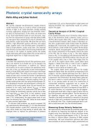
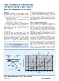
Special 30th AnniversaryHow the Double-Heterostructure Laser Idea got startedHerbert KroemerIn <strong>August</strong> 1952, I was hired as “Resident Theorist” by thesmall semiconductor research group at the CentralTelecommunications Technology Office [FernmeldetechnischesZentralamt (FTZ)] <strong>of</strong> the German Postal Service in Darmstadt,Germany. I had just received a doxtoral degree in TheoreticalSolid State Physics from the University <strong>of</strong> Göttingen, with adissertation on what we would today call hot-electron transporteffects, <strong>of</strong> the kind that were thought to play a role in the collector<strong>of</strong> the then-new transistor. In the process, I had acquiredwhat by 1952 standards was a good background in semiconductorphysics, including the emerging device physics. It wasan unusual background for a 1952 Theoretical Physicist, but itwas perfect for what was to come.The FTZ group was at that time working on the first bipolarjunction transistors. These early devices were far too slowfor practical applications in telecommunications, and I setmyself the task <strong>of</strong> understanding the frequency limitationstheoretically—and what to do about them. One approach wasto speed up the flow <strong>of</strong> the minority carriers from the emitterto the collector by incorporating an electric field into the baseregion, by using a non-uniform doping in the base, whichdecreased exponentially from the emitter end to the collectorend. While working out the details, I realized that“... a drift field may also be generated through a variation<strong>of</strong> the energy gap itself, by making the base region from a nonstoichiometricmixed crystal <strong>of</strong> different semiconductors withdifferent energy gaps (for example, Ge-Si), with a compositionthat varies continuously through the base.” ([1]; translated)This was not yet a full general design principle, but a seedhad been planted. Because <strong>of</strong> the absence <strong>of</strong> any credible technology,I did not follow up on this idea until 1957, after I hadjoined RCA Laboratories in Princeton, NJ. At that time, the1954 seed had germinated: I had realized the generality <strong>of</strong> thedesign principle hinted at in the above sentence, and publisheda (widely ignored) paper in the RCA Review (neverpublish in obscure journals!), which included the figure shownbelow, and the accompanying paragraph <strong>of</strong> text [2]:‘In a homogeneous semiconductor the band slope under anelectric field is the same for all bands and, as a result, theforces upon electrons and holes are equal in magnitude andopposite in direction. This is not the case with a varying bandgap. If the concept <strong>of</strong> a varying band gap is a legitimate one,the forces would no longer be equal and opposite. It should,for example, be possible to have force acting only upon onekind <strong>of</strong> the carriers, or to have a force which acts in the samedirection for both (Fig. 1). Electrical forces in uniform crystalscan never do this. This is why we call these forces “quasi-electric”forces. They present a new degree <strong>of</strong> freedom for thedevice designer which enables him to obtain effects with thequasi-electric forces that are basically impossible to obtainwith ordinary circuit means involving only “real” electricfields.’ [Emphasis added]As an example, I quoted the improved bipolar transistor.However, that still did not draw on the full power <strong>of</strong> the ideaexpressed in the general design principle that the quasi-electricfields ‘enable the device designer to obtain effects that arebasically impossible to obtain using only “real” electric fields.’It certainly represents major improvements, but does it representsomething “basically impossible” otherwise?Something that was indeed truly impossible to achieve otherwiseemerged abruptly in March 1963. I was working atVarian Associates in Palo Alto at the time, where a colleague<strong>of</strong> mine—Dr. Sol Miller—had taken a strong interest in thefirst semiconductor junction lasers that had emerged in 1962,a topic then outside my own range <strong>of</strong> interests. In a colloquiumon the topic he gave a beautiful review <strong>of</strong> what had beenachieved, not failing to point out that successful laser actionrequired either low temperatures or short low-duty-cycle pulses,usually both. Asked what the chances were to achieve con-(a)(b)(c)−qF+qFFe = 0qF h−qFe+qF hECE DEPARTMENT AND MATERIALS DEPARTMENT UNIVERSITY OFCALIFORNIA, SANTA BARBARA, CA 93106Figure. 1: (a) Effect <strong>of</strong> a true electric field; (b) and (c): Effects <strong>of</strong>quasi-electric fields.4 <strong>IEEE</strong> LEOS NEWSLETTER <strong>August</strong> 2007
Accelerating the pace <strong>of</strong> engineering and scienceHablasMATLAB??Over one million people around theworld speak MATLAB. Engineers andscientists in every field from aerospaceand semiconductors to biotech,financial services, and earth and oceansciences use it to express their ideas.Do you speak MATLAB?Mars Global Surveyoraltitude data, projectedon a sphere.This example available atmathworks.com/ltc©2007 The MathWorks, Inc. Data source: NASAThe language <strong>of</strong> technical computing.
tinuous operation at room temperature, Miller replied thatcertain experts had concluded that this was fundamentallyimpossible. The argument ran roughly as follows. In order toobtain laser action, a population inversion has to be achieved,which means that, in the active region, the occupation probability<strong>of</strong> the lowest states in the conduction band has to behigher than that <strong>of</strong> the highest states in the valence band. Anecessary condition for such a population inversion is a forwardbias larger than the energy gap. Even then, a populationinversion is hard to achieve in an ordinary p-n junction. Thecarrier concentrations in the active region will always be lowerthan in the doped contact regions. Inversion, therefore,required degenerate doping on both sides. Even then, both theelectrons and holes would diffuse out <strong>of</strong> the active regionimmediately into the adjacent oppositely doped region, preventinga population inversion from building up.I immediately protested against this argument with wordssomewhat like “but that is a pile <strong>of</strong> .... , all one has to do isgive the injector regions a wider energy gap.” To me, thiswould cause an electron-repelling quasi-electric field to bepresent on the p side, and a similar hole-repelling barrier onthe n side. Carrier confinement would thus be achieved. Infact, electron and hole concentrations could be much largerthan the doping levels in the contact regions (for details, seemy Nobel Lecture [4]), and it would become readily possibleto create the population inversion necessary for laser action.This double-heterostructure (DH) laser finally represented adevice truly impossible with only the real electric fields availablein homostructures. Note that the idea for it arose essentiallyat the instant I had been made aware that there was aproblem.The rest is history.I wrote up a paper describing the DH idea, along with apatent application. The paper was submitted to AppliedPhysics Letters, where it was rejected. I was urged not to fightthe rejection, but to submit the paper to the Proceedings <strong>of</strong>the <strong>IEEE</strong> instead, where it was published [3], but largelyignored. The patent was issued in 1967 [5]. It is probably abetter paper than the Proc. <strong>IEEE</strong> letter. It expired in 1985.Both the <strong>IEEE</strong> letter and the patent draw on an extensiveunpublished corporate report that might be <strong>of</strong> interest to readerswishing to go deeper into the history <strong>of</strong> the subject [6].When I proposed to develop the technology for the DHlaser, I was refused the resources to do so, on the grounds that“this device could not possibly have any practical applications,”or words to that effect. It was a classical case <strong>of</strong> judginga fundamentally new technology, not by what new applicationsit might create, but merely by what it might do foralready-existing applications. This is extraordinarily shortsighted,but the problem is pervasive, as old as technologyitself. The DH laser was simply another example in a longchain <strong>of</strong> similar examples. Nor will it be the last. Any detailedlook at history provides staggering evidence for what I havecalled the Lemma <strong>of</strong> New Technology:The principal applications <strong>of</strong> any sufficiently new and innovativetechnology have always been — and will continue to be —applications created by that technology.As a rule, such applications have indeed arisen—the DHlaser is just a good recent example—although usually notimmediately.References:[1] H. Krömer, Archiv d. Elekt. Übertragung 8, 499 (1954).[2] H. Kroemer, RCA Review 18, 332 (1957).[3] —, Proc. <strong>IEEE</strong> 51, 1782 (1963).[4] —, Revs. Mod. Phys. 73, 783 (2001)[4] —, US patent 3,309,553 (filed Aug. 16, 1963, issued 1967).[5] —, Varian Central Research Report CRR-36 (1963); unpublished(available from the author as <strong>PDF</strong> copy).Biography: Herbert KroemerHerbert Kroemer is Pr<strong>of</strong>essor <strong>of</strong> Electrical and ComputerEngineering and <strong>of</strong> Materials at UCSB. He was born and educatedin Germany. In 1952 he received a Doctorate in Physicsfrom the University <strong>of</strong> Göttingen, Germany. Since then, hehas worked on the physics and technology <strong>of</strong> semiconductorsand semiconductor devices, especially heterostructures. Heoriginated several key device concepts, including the heterostructurebipolar transistor and the double-heterostructurelaser. He is a Member <strong>of</strong> the National Academy <strong>of</strong>Engineering and the National Academy <strong>of</strong> Sciences. He holdshonorary doctorates from the Technical University <strong>of</strong> Aachen,Germany, from the University <strong>of</strong> Lund, Sweden, from theUniversity <strong>of</strong> Colorado, and from the University <strong>of</strong> Duisburg-Essen, Germany. He has received numerous awards, mostrecently, in 2000, the Nobel Prize in Physics, “for developingsemiconductor heterostructures used in high-speed and optoelectronics,”and in 2002 the <strong>IEEE</strong> Medal <strong>of</strong> Honor.6 <strong>IEEE</strong> LEOS NEWSLETTER <strong>August</strong> 2007
one hundred fifty years <strong>of</strong> contentfifteen leaders in science & technology researchthree million documentsone gateway to it allSearch scitopia.org to fi nd quality content from leaders in scienceand technology research. Scitopia.org generates relevant andfocused results – with no Internet noise. From peer-reviewed journalarticles and technical conference papers to patents and more,scitopia.org is a researchers’ heaven on earth.searchIntegrating Trusted Science + Technology ResearchScitopia.org was founded by: Acoustical <strong>Society</strong> <strong>of</strong> America · American GeophysicalUnion · American Institute <strong>of</strong> Physics · American Physical <strong>Society</strong> · American <strong>Society</strong><strong>of</strong> Civil Engineers · American <strong>Society</strong> <strong>of</strong> Mechanical Engineers · American Vacuum<strong>Society</strong> · ECS · <strong>IEEE</strong> · Institute <strong>of</strong> Aeronautics and Astronautics · Institute <strong>of</strong>Physics Publishing · Optical <strong>Society</strong> <strong>of</strong> America · <strong>Society</strong> <strong>of</strong> Automotive Engineers ·<strong>Society</strong> for Industrial and Applied Mathematics · SPIE07-PIM-0130_Scitopia_Ad_A_Rev1.i1 15/3/07 8:40:14 AM
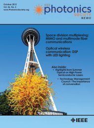
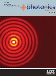
Special 30th AnniversarySemiconductor Saturable Absorber Mirrors(SESAM’s) for Femtosecond to NanosecondPulse Generation in Solid-State LasersReprint <strong>of</strong> most cited article from JSTQE Vol. 2, No. 3, Sept 1996Ursula Keller, Kurt J. Weingarten, Franz X. Kärtner, Daniel Kopf, Bernd Braun, IsabellaD. Jung, Regula Fluck, Clemens Hönninger, Nicolai Matuschek, and Juerg Aus der AuAbstractIntracavity semiconductor saturable absorber mirrors (SESAM’s)<strong>of</strong>fer unique and exciting possibilities for passively pulsed solidstatelaser systems, extending from Q-switched pulses in thenanosecond and picosecond regime to mode-locked pulses from10’s <strong>of</strong> picoseconds to sub-10 fs. This paper reviews the designrequirements <strong>of</strong> SESAM’s for stable pulse generation in both themode-locked and Q-switched regime. The combination <strong>of</strong> devicestructure and material parameters for SESAM’s provide sufficientdesign freedom to choose key parameters such as recovery time, saturationintensity, and saturation fluence, in a compact structurewith low insertion loss. We have been able to demonstrate, forexample, passive modelocking (with no Q-switching) using anintracavity saturable absorber in solid-state lasers with long upperstate lifetimes (e.g., 1-μm neodymium transitions), Kerr lens modelockingassisted with pulsewidths as short as 6.5 fs from a Ti:sapphirelaser—the shortest pulses ever produced directly out <strong>of</strong> a laser“Single”ModeMultiModePowerPowerCW - RunningTimeQ - Switched Mode LockingTimeCW - Q - SwitchingCW - Mode LockingFigure 1: Different modes <strong>of</strong> operation <strong>of</strong> a laser with a saturable absorber. CW Q-switching typically occurs with much longer pulses and lower pulse repetition rates thanCW mode-locking.MANUSCRIPT RECEIVED SEPTEMBER 24, 1996; REVISED JANUARY 9, 1997.THE AUTHORS ARE WITH THE INSTITUTE OF QUANTUM ELECTRONICS, SWISS FEDERAL INSTITUTE OFTECHNOLOGY (ETH), ETH-HÖNGGERBERG HPT, CH-8093 ZÜRICH, SWITZERLAND.PUBLISHER ITEM IDENTIFIER S 1077-260X(96)09675-X.PowerSelf-Starting Mode LockingPowerTimeTimewithout any external pulse compression, and passive Q-switchingwith pulses as short as 56 ps—the shortest pulses ever produceddirectly from a Q-switched solid-state laser. Diode-pumping <strong>of</strong>such lasers is leading to practical, real-world ultrafast sources, andwe will review results on diode-pumped Cr:LiSAF, Nd:glass,Yb:YAG, Nd:YAG, Nd:YLF, Nd:LSB, and Nd:YVO 4 .Historical Background and IntroductionSemiconductor Saturable Absorbersfor Solid-State LasersThe use <strong>of</strong> saturable absorbers in solid-state lasers is practicallyas old as the solid-state laser itself [1]–[3]. However, it wasbelieved that pure, continuous-wave (CW) modelocking couldnot be achieved using saturable absorbers with solid-state laserssuch as Nd:glass, Nd:YAG, or Nd:YLF with long upper statelifetimes (i.e., >100 μs) without Q-switching orQ-switched mode-locked behavior (Fig. 1).This limitation was mostly due to the parameterranges <strong>of</strong> available saturable absorbers [4].However, the advent <strong>of</strong> bandgap engineeringand modern semiconductor growth technologyhas allowed for saturable absorbers with accuratecontrol <strong>of</strong> the device parameters such asabsorption wavelength, saturation energy, andrecovery time, and we have been able todemonstrate pure passive Q-switching, pureCW modelocking or, if desired, Q-switchedmodelocking behavior [5]–[9]. In addition,semiconductor absorbers have an intrinsic bitemporalimpulse response (Fig. 2): intraband carrier–carrierscattering and thermalization processeswhich are in the order <strong>of</strong> 10 to 100 fs as well asinterband trapping and recombination processeswhich can be in the order <strong>of</strong> picoseconds tonanoseconds depending on the growth parameters[10], [11]. As we will discuss, the faster saturableabsorption plays an important role in stabilizingfemtosecond lasers, while the slowerresponse is important for starting the pulse formationprocess and for pulse forming in laserswith pulsewidths <strong>of</strong> picoseconds or longer.Many other classes <strong>of</strong> laser can be passivelymode-locked with saturable absorbers.Previously, semiconductor saturable absorbers8 <strong>IEEE</strong> LEOS NEWSLETTER <strong>August</strong> 2007
PowerTO THE PEOPLE<strong>IEEE</strong> MemberDigital LibraryWhat separates you from researchers atthe world’s largest institutions?Nothing — if you subscribe to the <strong>IEEE</strong>Member Digital Library.■ The only way for individuals to access any<strong>IEEE</strong> journal or conference proceeding■ Over a million full-text documents■ The latest online research, plus a 50 yeararchive for select titles■ The top-cited publications, all at yourfingertipsPower up. Learn more at:www.ieee.org/ieeemdl718-Qh MDL People 7x10.indd 16/26/06 10:07:16 AM
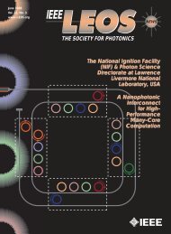
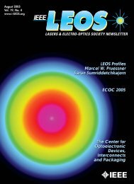
AbsorptionIntrabandThermalization≈ 100 fsLoss Loss LossGainTimeEDensity <strong>of</strong> States DFigure 2: A measured impulse response typical for a semiconductor saturable absorber.The optical nonlinearity is based on absorption bleaching.GainGainFigure 3: The three fundamental passive mode-locking models: (a)passive mode-locking with a slow saturable absorber and dynamicgain saturation [27], [28], (b) fast absorber mode-locking [29],[30], and (c) soliton mode-locking [31]–[33].have been successfully used to mode-locked semiconductor diodelasers, where the recovery time was reduced by damage inducedeither during the aging process [12], by proton bombardment[13], or by multiple quantum wells [14]. More recently, both bulkand multiple quantum-well semiconductor saturable absorbershave been used to mode-lock color center lasers [15]. In both cases,the upper state lifetime <strong>of</strong> the laser medium is in the nanosecondregime, which strongly reduces the tendency for self-Q-switchinginstabilities (discussed further in Section II). This is not the case formost other solid-state lasers with an upper state laser lifetime inthe microsecond to millisecond regime. First results with SESAM’sin solid-state lasers were reported in 1990, and they were initiallyused in nonlinear coupled cavities [16]–[21], a technique termedRPM (resonant passive mode-locking). This paper was motivatedby previously demonstrated soliton lasers [22] and APM (additivepulse mode-locking) lasers [23]–[25], where a nonlinear phaseshift in a fiber inside a coupled cavity provided an effective saturableabsorption. Most uses <strong>of</strong> coupled cavity techniques havebeen supplanted by intracavity saturable absorber techniquesbased on Kerr lens mode-locking (KLM) [26] and SESAM’s [5],due to their more inherent simplicity. In 1992, we demonstrateda stable, purely CW-mode-locked Nd:YLF and Nd:YAG laserusing an intracavity SESAM design, referred to as the antiresonantFabry–Perot saturable absorber (A-FPSA) [5]. Since then, manynew SESAM designs have been developed (see Section III) thatDInterbandRecombination≈ nsLT Grown Materials:Electron Trapping≈ ps - nsEprovide stable pulse generation for a variety <strong>of</strong>solid-state lasers.Mode-Locking Mechanism for Solid-State Lasers: Fast-Saturable-AbsorberMode-Locking or Soliton Mode-LockingD Passive mode-locking mechanisms are wellexplainedby three fundamental models: slow saturableabsorber mode-locking with dynamic gainsaturation [27], [28] [Fig. 3(a)], fast saturableabsorber mode-locking [29], [30] [Fig. 3(b)] andsoliton mode-locking [31]–[33] [Fig. 3(c)]. Inthe first two cases, a short net-gain window formsand stabilizes an ultrashort pulse. This net-gainwindow also forms the minimal stability requirement,i.e., the net loss immediately before andafter the pulse defines its extent. However, insoliton mode-locking, where the pulse formationis dominated by the balance <strong>of</strong> group velocity dispersion (GVD)and self-phase modulation (SPM), we have shown that the net-gainwindow can remain open for more than ten times longer than theultrashort pulse, depending on the specific laser parameters [32]. Inthis case, the slower saturable absorber only stabilizes the solitonand starts the pulse formation process.Until the end <strong>of</strong> the 1980’s, ultrashort pulse generation wasdominated by dye lasers, where mode-locking was based on a balancedsaturation <strong>of</strong> both gain and loss, opening a steady-state netgain window as short as the pulse duration [Fig. 3(a)] (the slowabsorberwith dynamic gain saturation model [27], [28]). Pulses asshort as 27 fs with an average power <strong>of</strong> ≈10 mW were generated[34]. Shorter pulse durations to 6 fs were achieved through additionalamplification and fiber-grating pulse compression, althoughat much lower repetition rates [35].The situation changed with the development and commercialization<strong>of</strong> the Ti:sapphire laser [36], which has a gain-bandwidthlarge enough to support ultrashort pulse generation. However,existing mode-locking techniques were inadequate because <strong>of</strong> themuch longer upper state lifetime and the smaller gain cross section<strong>of</strong> this laser, which results in negligible pulse-to-pulse dynamicgain saturation. Initially it was assumed that a fast saturableabsorber would be required to generate ultrashort pulses [Fig. 3(b)].Such a fast saturable absorber was discovered [26] and its physicalmechanism described as Kerr lens mode-locking (KLM) [19], [37],[38], where strong self-focusing <strong>of</strong> the laser beam combined witheither a hard aperture or a “s<strong>of</strong>t” gain aperture is used to produce aself amplitude modulation, i.e., an equivalent fast saturableabsorber. Since then, significant efforts have been directed towardoptimizing KLM for shorter pulse generation, with the currentresults standing at around 8 fs [39]–[41] directly from the laser.Using a broad-band intracavity SESAM device in addition to KLMand higher order dispersion compensation [42], [43] we recentlygenerated pulses as short as 6.5 fs [Fig. 12(b)] directly out <strong>of</strong> aTi:sapphire laser with 200 mW average output power at a pulserepetition rate <strong>of</strong> ≈85 MHz [44]. External pulse compression techniquesbased on fiber-grating pulse compressors have been used t<strong>of</strong>urther reduce the pulse duration from a Ti:sapphire laser to ≈5 fsat a center wavelength <strong>of</strong> ≈800 nm [45], [46]. These are currentlythe shortest optical pulses ever generated.Density <strong>of</strong> States D10 <strong>IEEE</strong> LEOS NEWSLETTER <strong>August</strong> 2007
Besides the tremendous success <strong>of</strong> KLM, there are some significantlimitations for practical or “real-world” ultrafast lasers. First,the cavity is typically operated near one end <strong>of</strong> its stability range,where the Kerr-lens-induced change <strong>of</strong> the beam diameter is largeenough to sustain mode-locking. This results in a requirement forcritical cavity alignment where mirrors and laser crystal have to bepositioned to an accuracy <strong>of</strong> several hundred microns typically.Additionally, the self-focusing required for KLM imposes limitationson the cavity design and leads to strong space-time coupling<strong>of</strong> the pulses in the laser crystal that results in complex laser dynamics[47], [48]. Once the cavity is correctly aligned, KLM can be verystable and under certain conditions even self-starting [49], [50].However, self-starting KLM lasers in the sub-50-fs regime have notyet been demonstrated without any additional starting mechanismsas for example a SESAM. This is not surprising, since in a 10-fsTi:sapphire laser with a 100 MHz repetition rate, the peak powerchanges by six orders <strong>of</strong> magnitude when the laser switches fromCW to pulsed operation. Therefore, nonlinear effects that are stilleffective in the sub-10-fs regime are typically too small to initiatemode-locking in the CW-operation regime. In contrast, if self-startingis optimized, KLM tends to saturate in the ultrashort pulseregime or the large SPM will drive the laser unstable.However, we have shown that a novel mode-locking technique,which we term soliton mode-locking [31]–[33], [51],addresses many <strong>of</strong> these issues. In soliton mode-locking, the pulseshaping is done solely by soliton formation, i.e., the balance <strong>of</strong>GVD and SPM at steady state, with no additional requirementson the cavity stability regime. An additional loss mechanism,such as a saturable absorber [31], [33], or an acousto-optic modelocker[51], [52], is necessary to start the mode-locking processand to stabilize the soliton.This can be explained as follows. The soliton loses energy due togain dispersion and losses in the cavity. Gain dispersion and lossescan be treated as perturbation to the nonlinear Schrödinger equationfor which a soliton is a stable solution [51]. This lost energy,called continuum in soliton perturbation theory [53], is initiallycontained in a low intensity background pulse, which experiencesnegligible bandwidth broadening from SPM, but spreads in timedue to GVD. This continuum experiences a higher gain comparedto the soliton, because it only sees the gain at line center (while thesoliton sees an effectively lower average gain due to its larger bandwidth).After a sufficient build-up time, the continuum wouldactually grow until it reaches an effective lasing threshold, destabilizingthe soliton. However, we can stabilize the soliton by introducinga “slow” saturable absorber into the cavity. This slowabsorber adds sufficient additional loss so that the continuum nolonger reaches threshold, but with negligible increased loss for theshort soliton pulse.Depending on the specific laser parameters such as gain dispersion,small signal gain, and negative dispersion, a “slow” saturableabsorber can stabilize a soliton with a response time <strong>of</strong> morethan ten times longer than the steady-state soliton pulsewidth[Fig. 3(c)]. High-dynamic range autocorrelation measurementshave shown ideal transform-limited soliton pulses over more thansix orders <strong>of</strong> magnitude, even though the net gain window is openmuch longer than the pulse duration [32], [54], [55]. Due to theslow saturable absorber, the soliton undergoes an efficient pulsecleaning mechanism [33]. In each round-trip, the front part <strong>of</strong> thesoliton is absorbed which delays the soliton with respect to thecontinuum.In contrast to KLM, soliton mode-locking is obtained over thefull cavity stability regime, and pulses as short as 13 fs have beengenerated currently with a purely soliton-mode-locked Ti:sapphirelaser using a broad-band SESAM [33], [56]. Soliton mode-lockingdecouples SPM and self-amplitude modulation, potentially allowingfor independent optimization. We justify the introduction <strong>of</strong> anew name for this mode-locking process because previously solitoneffects were only considered to lead to a moderate additionalpulsewidth reduction <strong>of</strong> up to a factor <strong>of</strong> 2, but the stabilization wasstill achieved by a short net gain window as discussed for CPM dye[57]–[60] and for KLM Ti:sapphire lasers [61], [62].Design Criteria for a Saturable AbsorberFirst we consider the basic design parameters <strong>of</strong> a general saturableabsorber. These consist <strong>of</strong> the saturation intensity I sat and saturationfluence E sat , which will be seen to influence the mode-lockingbuild-up and the pulse stability with respect to self-Q-switching. Inaddition, the recovery time <strong>of</strong> the saturable absorber determines thedominant mode-locking mechanism, which is either based on fastsaturable absorber mode-locking [Fig. 3(b)] in the positive or negativedispersion regime, or soliton mode-locking [Fig. 3(c)], whichoperates solely in the negative dispersion regime. For solid-statelasers we can neglect slow saturable absorber mode-locking asshown in Fig. 3(a), because no significant dynamic gain saturationis taking place due to the long upper state lifetime <strong>of</strong> the laser.When the recovery time <strong>of</strong> the absorber is on the order <strong>of</strong> or evenlarger than the laser’s cavity round-trip time, the laser will tend tooperate in the pure CW-Q-switching regime (Fig. 1).In addition, the nonsaturable losses <strong>of</strong> a saturable absorberneed to be small, because we typically only couple a few percentout <strong>of</strong> a CW mode-locked solid-state laser. As the nonsaturablelosses increase, the laser becomes less efficient andoperates fewer times over threshold, which increases the tendencyfor instabilities [see (4) and (6) below] such asQ-switched mode-locked behavior.Fig. 4 shows the typical saturation behavior for an absorber on amirror. Initially, the pulses are formed by noise fluctuations in thelaser, and the saturation amount at this early stage is dominated bythe CW intensity I incident on the absorber [Fig. 4(a)]. In general,we can assume that the saturable absorber is barely bleached (i.e.,I ≪ I sat ) at CW intensity, because if the absorber were fullybleached at this intensity, there would be insufficient further modulationto drive the pulse forming process.The saturation intensity I sat is given byI sat = hv(1)σ A T Awhere hv is the photon energy, σ A the absorption cross section andT A the absorber recovery time. It is important to note that theabsorption cross section is effectively a material parameter. Theabsorption coefficient α <strong>of</strong> the material is then given byα = σ A N D (2)where N D is the density <strong>of</strong> absorber atoms or the density <strong>of</strong> statesin semiconductors, for example.<strong>August</strong> 2007 <strong>IEEE</strong> LEOS NEWSLETTER 11
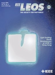
Absorber ReflectivityAbsorber ReflectivityR(E p )R(I)E sat =Intensity on Absorberhνσ effdRdII sat =hνσ eff τ c(a)dRdE pPulse Energy Density on Absorber(b)Figure 4: Nonlinear reflectivity change <strong>of</strong> a saturable absorbermirror due to absorption bleaching with the (a) CW intensity and(b) short pulses. I sat is the saturation intensity, E sat is the saturationfluence, I is the CW intensity, and I p is the pulse energy densityincident on the saturable absorber.Referring again to Fig. 4(a), the slope dR/dIat around I ≈ 0determines the mode-locking build-up time under certain approximations[9] can be written as1T build–up ∝dRdI | (3)I≈0 IAs expected, the build-up time is inversely proportional to thisslope. This follows directly from Fig. 4(a), which shows that smallintensity fluctuations will introduce a larger reflectivity change <strong>of</strong>the saturable absorber if the slope is larger. Therefore, the modelockingbuild-up time decreases with smaller saturation intensities.However, there is a trade<strong>of</strong>f: if the saturation intensity is too small,the laser will start to Q-switch. The condition for no Q-switching isderived in [4], [9]:no Q-switching:dR∣ dI∣ I < r T R≈ T R. (4)τ 2 τ stimwhere r is the pump parameter that determines how many timesthe laser is pumped above threshold, T R is the cavity round triptime, and τ 2 is the upper state lifetime <strong>of</strong> the laser. The stimulatedlifetime τ stim <strong>of</strong> the upper laser level is given byτ stim = τ 2 /(r − 1) ≈ τ 2 /r for r ≫ 1. The small signal gain <strong>of</strong>the laser is given by g 0 = rl, where l is the total loss coefficient <strong>of</strong>the laser cavity. From (4), it then follows that Q-switching can bemore easily suppressed for a small slope dR/dI(i.e., a large saturationintensity), a large r (i.e., a laser that is pumped far above thresholdwith a large small-signal gain g 0 or small losses l ), a large cavityround-trip period (i.e., for example a low mode-locked pulseIMultiplePulsingInstabilitiesE p >> E satE prepetition rate). Equation (4) also indicates that solid-state laserswith a large upper state lifetime τ 2 will have an increased tendencyfor self-Q-switching instabilities.The physical interpretation <strong>of</strong> the Q-switching threshold (4) isas follows: The left-hand side <strong>of</strong> (4) determines the reduction inlosses per cavity round-trip due to the bleaching in the saturableabsorber. This loss reduction will increase the intensity inside thelaser cavity. The right-hand side <strong>of</strong> (4) determines how much thegain per round-trip saturates, compensating for the reduced lossesand keeping the intensity inside the laser cavity constant. If thegain cannot respond fast enough, the intensity continues to increaseas the absorber is bleached, leading to self-Q-switching instabilitiesor stable Q-switching.Equations (3) and (4) give an upper and lower bound for the saturationintensity which results in stable CW mode-locking withoutself-Q-switching. Of course, we can also optimize a saturableabsorber for Q-switching by selecting a small saturation intensityand a short cavity length, i.e., a short T R . This will be discussed inmore detail in Section V.If we use a fast saturable absorber with recovery time muchshorter than the cavity round-trip time (T A ≪ T R ), then the conditionsgiven by (3) and (4) are typically fulfilled and much shorterpulses can be formed. But now, an additional stability requirementhas to be fulfilled to prevent Q-switched mode-locking (Fig. 1). Forthis further discussion, we assume that the steady-state pulse durationτ p is shorter than the recovery time T A <strong>of</strong> the saturableabsorber, i.e., τ p < T A . In this case the saturation [Fig. 4(b)] isdetermined by the saturation fluence E sat , given byE sat = hv(5)σ Aand the incident pulse energy density E p on the saturable absorber.The loss reduction per round-trip is now due to bleaching <strong>of</strong> thesaturable absorber by the short pulses, not the CW intensity. Thisis a much larger effect when T A ≪ T R . Therefore, in analogy to (4),we can show that the condition to prevent Q-switched mode-lockingis given by [9]:no Q-switched mode-locking:∣ dR ∣∣∣∣ E p < r T R≈ T R. (6)dE p τ 2 τ stimWe can easily fulfill this condition by choosing E p ≫ E sat [Fig.4(b)]. This also optimizes the modulation depth, resulting inreduced pulse duration.However, there is also an upper limit to E p , determined by theonset <strong>of</strong> multiple pulsing [63]. Given an energy fluence many timesthe saturation energy fluence E sat , we can see that the reflectivity isstrongly saturated and no longer a strong function <strong>of</strong> the pulse energy.In addition, shorter pulses see a reduced average gain, due to thelimited gain bandwidth <strong>of</strong> the laser. Beyond a certain pulse energy,two pulses with lower power, longer duration, and narrower spectrumwill be preferred, since they see a larger increase <strong>of</strong> the averagegain but a smaller increase in the absorption. The threshold formultiple pulsing is lower for shorter pulses, i.e., with spectrumsbroad compared to the gain bandwidth <strong>of</strong> the laser. Our experimentallydetermined rule <strong>of</strong> thumb for the pulse energy density onthe saturable absorber is three to five times the saturation fluence.12 <strong>IEEE</strong> LEOS NEWSLETTER <strong>August</strong> 2007
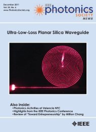
0.840Absorption Bleaching on Mirror0.70.60.5380°C315°C260°CElectron Trapping Time (ps)3020100.4200°C2 4 6 8 2 4 6 810 100 1000Energy Density (μJ/cm 2 )(a)0200 250 300 350 400MBE Growth Temperature (°C)(b)Figure 5: Measured absorption bleaching and electron trapping times (i.e., recovery time <strong>of</strong> saturable absorber) for low-temperature MBE grownInGaAs–GaAs multiple quantum-well absorbers. The MBE growth temperature is the variable parameter used in the nonlinear reflectivity.A more detailed description <strong>of</strong> multiple pulsing willbe given elsewhere. In general, the incident pulseenergy density on the saturable absorber can beadjusted by the incident mode area, i.e., how stronglythe cavity mode is focused onto the saturableabsorber.Equations (3), (4), and (6) give general criteria forthe saturation intensity I sat (1) and saturation fluenceE sat (5) <strong>of</strong> the saturable absorber. Normally, the saturationfluence <strong>of</strong> the absorber material is a given, fixedparameter, and we have to adjust the incident modearea to set the incident pulse energy density onto thesaturable absorber to fulfill the conditions given by(6) and the multiple pulsing instabilities. Therefore,the only parameter left to adjust for the saturationintensity is the absorber recovery time T A (1).However, if we want to use the absorber as a fast saturableabsorber, we have to reduce T A .Semiconductor materials are interesting in thisregard, because we can adjust T A from the nanosecondto the subpicosecond regime using differentgrowth parameters (Section III-A). In this case, however,it is <strong>of</strong>ten necessary to find another parameterwith which to adjust I sat rather than with T A . Wewill show in the next section that this can be obtainedby using semiconductor saturable absorbers inside adevice structure which allows us to modify the effectiveabsorber cross section σ A (1), which is a fixedmaterial parameter. For cases where the cavity designis more restricted and the incident mode area on the<strong>August</strong> 2007 <strong>IEEE</strong> LEOS NEWSLETTER 13
saturable absorber is not freely adjustable, modifying the devicestructure <strong>of</strong>fers an interesting solution for adjusting the effectivesaturation fluence <strong>of</strong> the SESAM device to the incident pulse energydensity. This is particularly useful for the passively Q-switchedmonolithic ring lasers [64] and microchip lasers [65], [66], discussedin more detail in Section V.Semiconductor Saturable AbsorberMirror (SESAM) DesignMaterial and Device ParametersNormally grown semiconductor materials have a carrier recombinationtime in the nanosecond regime, which tends to drive manyOutput Power, mWPulse Spectra1401201008060402001.00.80.60.40.20.00.0800 820 840 860 880 900Figure 6: Tunability <strong>of</strong> a diode-pumped Cr:LiSAF laser using an intracavity lowfinesseA-FPSA. Pulsewidth as short as 45 fs has been achieved. The Tunability <strong>of</strong>≈ 50 nm was limited by the lower AlGaAs–AlAs Bragg mirror <strong>of</strong> the A-FPSA.High-FinesseA-FPSAR=95%Sat. Abs.Wavelength, nmThin AbsorberAR-CoatedR=0%Sat. Abs.Output PowerPulse WidthLow-FinesseA-FPSA(*SBR)R≈30%Sat. Abs.solid-state lasers into Q-switching instabilities (Section II). In addition,nanosecond recovery times do not provide a fast enough saturableabsorber for CW mode-locking. We use low-temperaturegrown III–V semiconductors [5], [7], [67] which exhibit fast carriertrapping into point defects formed by the excess group-V atomsincorporated during the LT growth [11], [68], [69]. Fig. 5 showstypical electron trapping times (i.e., absorber recovery times) andthe nonlinear absorption bleaching as a function <strong>of</strong> MBE growthtemperature. For growth temperatures as low as 250 ◦ C, we stillobtain a good nonlinear modulation <strong>of</strong> the saturable absorber withrecovery times as low as a few picoseconds. The trade<strong>of</strong>f here is thatthe nonsaturable absorber losses for E p ≫ E sat increase withreduced growth temperatures [8]. This trade<strong>of</strong>f will ultimatelylimit the maximum thickness <strong>of</strong> the absorber materialused inside a solid-state laser cavity.D-SAMSat. Abs. andNegative Disp.Sat. Abs.R>99.5%R>98% R>99.5% R>99.5%2001501005001.00.80.60.40.2Pulse Width, fs ReflectivityFor femtosecond pulse generation, we can benefitfrom the intraband thermalization processes that occurwith time constants from tens to hundreds <strong>of</strong> femtoseconds,depending on the excitation intensity andenergy [70]. A larger femtosecond modulation depthcan be obtained for quantum-well structures because<strong>of</strong> the approximately constant density <strong>of</strong> states abovethe bandgap. However, we can strongly reduce therequirements on this fast recovery time if we do notuse the semiconductor saturable absorber as a fast saturableabsorber, according to Fig. 3(b), but just to startand stabilize soliton mode-locking. In this case, noquantum-well effects are absolutely necessary and,therefore, bulk absorber layers are in most cases sufficientas well. The reduced requirements on theabsorber dynamics also allowed us to demonstrate 50-nm tunability <strong>of</strong> a diode-pumped, soliton-modelockedCr:LiSAF laser with a one-quantum-well lowfinesseA-FPSA (Fig. 6) [71], [72]. We would notobtain this broad tunability if the excitonic nonlinearitiesin the SESAM provided the dominant pulse formationprocess. In addition, in the soliton mode-lockingregime we can also obtain pulses in the 10-fs rangeor below, even though the mode-locked spectrumextends beyond the bandgap <strong>of</strong> the semiconductor saturableabsorber, for example [56].R≈30%We can further adjust the keyparameters <strong>of</strong> the saturable absorber ifwe integrate the absorber layer into adevice structure. This allows us tomodify the effective absorber crosssection σ A (2) beyond its materialvalue, for example. In addition, wecan obtain negative dispersion compensationby using a Gire–Tournoismirror or chirped mirrors. In the following,we will discuss the differentdevice designs in more detail.April 92 Feb. 95 * June/July 95 April 96(a) (b) (c) (d)Figure 7: Different SESAM devices in historical order. (a) High-finesse A-FPSA. (b) Thin ARcoatedSESAM. (c) Low-finesse A-FPSA. (d) D-SAM.Overview <strong>of</strong> the DifferentSESAM DesignsSESAM’s <strong>of</strong>fer a distinct range <strong>of</strong>operating parameters not available14 <strong>IEEE</strong> LEOS NEWSLETTER <strong>August</strong> 2007
with other approaches. We use various designs <strong>of</strong> SESAM’s[73] to achieve many <strong>of</strong> the desired properties.Fig. 7 shows the different SESAM designs in historical order. Thefirst intracavity SESAM device was the antiresonant Fabry–Perotsaturable absorber (A-FPSA) [5], initially used in a design regimewith a rather high top reflector, which we call now more specificallythe high-finesse A-FPSA. The Fabry–Perot is typically formedby the lower semiconductor Bragg mirror and a dielectric top mirror,with a saturable absorber and possibly transparent spacer layersin between. The thickness <strong>of</strong> the total absorber and spacer layers areadjusted such that the Fabry–Perot is operated at antiresonance [(7),Figs. 8 and 9]. Operation at antiresonance results in a device that isbroad-band and has minimal group velocity dispersion (Fig. 8). Thebandwidth <strong>of</strong> the A-FPSA is limited by either the free spectralrange <strong>of</strong> the Fabry–Perot or the bandwidth <strong>of</strong> the mirrors.The top reflector <strong>of</strong> the A-FPSA is an adjustable parameter thatdetermines the intensity entering the semiconductor saturableabsorber and, therefore, the effective saturation intensity or absorbercross section <strong>of</strong> the device. We have since demonstrated a more generalcategory <strong>of</strong> SESAM designs, in one limit, for example, byreplacing the top mirror with an AR-coating [Fig. 7(b)] [74].Using the incident laser mode area as an adjustable parameter, wecan adapt the incident pulse energy density to the saturation fluence<strong>of</strong> the device (Section II). However, to reduce the nonsaturableinsertion loss <strong>of</strong> the device, we typically have toreduce the thickness <strong>of</strong> the saturable absorber layer.A special intermediate design, which we callthe low-finesse A-FPSA [Fig. 7(c)] [75]–[77], isachieved with no additional top coating resultingin a top reflector formed by the Fresnelreflection at the semiconductor/air interface,which is typically ≈30%.The dispersive saturable absorber mirror (D-SAM) [78] [Fig. 7(d)] incorporates both dispersionand saturable absorption into a device similar to alow-finesse A-FPSA, but operated close to resonance.The different advantages and trade<strong>of</strong>fs <strong>of</strong> thesedevices will be discussed below.mode-locking is typically well-described by the soliton mode-lockingmodel [31]–[33].Fig. 9 shows a typical high-finesse A-FPSA design for a laserwavelength ≈ 1.05 μm. The bottom mirror is a Bragg mirrorformed by 16 pairs <strong>of</strong> AlAs–GaAs quarter-wave layers with a complexreflectivity <strong>of</strong> R b e iϕb . In this case, the phase shift seen from theabsorber layer to the bottom mirror is ϕ b = π with a reflectivity <strong>of</strong>R b ≈ 98%, and to the top mirror ϕ t = 0 with R t ≈ 96% [8],[83]. The multiple-quantum-well (MQW) absorber layer has athickness d chosen such that the antiresonance condition is fulfilled:ϕ rt = ϕ b + ϕ t + 2k¯nd= (2m + 1)π (7)where ϕ rt is the round-trip phase inside the Fabry–Perot, ¯n is theaverage refractive index <strong>of</strong> the absorber layer, k = 2π/λ is thewavevector, λ is the wavelength in vacuum and m is a integer number.From (7), it follows that:d = m λ (8)2¯nFrom the calculated intensity distribution in Fig. 9, we see thatm = 4.The π-phase shift from the lower Bragg reflector in Fig. 9 mayI 0I c < I 0ΔRR topdSemiconductorSaturable AbsorberR bottomHigh-Finesse A-FPSAThe high-finesse antiresonant Fabry–Perot saturableabsorber (A-FPSA) device [5], [7] (Fig. 9) was thefirst intracavity saturable absorber that started andsustained stable CW mode-locking <strong>of</strong> Nd:YLF andNd:YAG lasers in 1992. Since then, other solid-statelasers such as Yb:YAG [77], Nd:LSB [79], Nd:YLF,and Nd:YVO 4 at 1.06 and 1.3 μm [80] have beenpassively mode-locked in the picosecond regimewith this design. In addition, high-finesse A-FPSAdevices have been used to passively Q-switchmicrochip lasers, generating pulses as short as 56 ps[66]. Femtosecond pulse durations τ p have been generatedwith Ti:sapphire (τ p = 19 fs) [76], Yb:YAG(τ p ≈ 500 fs) [77], diode-pumped Nd : glass (τ p =60–100 fs) [6], [54], [63], and Cr:LiSAF (τ p =45–100 fs) [52], [72], [81], [82] lasers. In thepicosecond regime, the A-FPSA acts as a fast saturableabsorber [29], and in the femtosecond regime,Group Delay dΦ /dω (fs)60 10040200Antiresonance−2000.95 1.00 1.05 1.10 1.15Wavelength (μm)Figure 8: Basic principle <strong>of</strong> the A-FPSA concept. With the top reflector, we can controlthe incident intensity to the saturable absorber section. The thickness <strong>of</strong> this absorbersection is adjusted for antiresonance. The typical reflectivity (dashed line) and groupdelay (solid line) is shown as a function <strong>of</strong> wavelength. At antiresonance, we have highbroad-bandreflection and minimal group delay dispersion.<strong>August</strong> 2007 <strong>IEEE</strong> LEOS NEWSLETTER 1580604020Reflectivity (%)
seem surprising initially, because the phase shift from the first interfacefrom the MQW absorber layer to GaAs is zero due to the factthat ¯n > n (GaAs). However, all the other layers from theAlAs–GaAs Bragg mirror add constructively with a phase shift <strong>of</strong>π at the beginning <strong>of</strong> the absorber layer. Therefore, this zero-phasereflection is negligible. We also could have chosen to stop the Braggreflector with the AlAs layer instead <strong>of</strong> the GaAs layer. However,we typically grow the Bragg reflector during a separate growth run,followed by a regrowth for the rest <strong>of</strong> the structure. For this reason,we chose to finish the Bragg reflector with the GaAs layer to reduceoxidation effects before the regrowth.The saturable absorber layer inside the high-finesse A-FPSA(Fig. 9) is typically extended over several periods <strong>of</strong> the standingwave pattern <strong>of</strong> the incident electromagnetic wave. This results inabout a factor <strong>of</strong> 2 increase <strong>of</strong> the saturation fluence and intensitycompared to the material value measured without standing-waveeffects. We typically measure a saturation fluence <strong>of</strong> ≈ 60 μJ/cm 2[8] for an AR-coated (i.e., R t = 0%) LT grown InGaAs–GaAsdevice. With a top reflector the effective saturation fluence isincreased as given by (13) and (14) <strong>of</strong> [8]. For a relatively high topreflector >95%, the effective saturation fluence is typicallyincreased by about two orders <strong>of</strong> magnitude.GaAs-SubstrateRefractive Index4321GaAsAIAsGaAsBottom Reflector(AIAs/GaAs Bragg Mirror)R b exp(iϕ b )Bottom Bragg Mirror16x AIAs/GaAsLT-MQWSaturable Absorber50x InGaAs/GaAs0.0 0.5dAbsorber LayerFigure 9: High-finesse A-FPSA: A specific design for a ≈1.05 μm center wavelength laser.The enlarged section also shows the calculated standing-wave intensity pattern <strong>of</strong> an incidentelectromagnetic wave centered at 1.05 μm. The Fabry–Perot is formed by the lower AlAs-GaAs Bragg reflector, the absorber layer <strong>of</strong> thickness ¯nd = 4 · λ/2 and a top SiO 2 /TiO 2Bragg reflector, where ¯n is the average refractive index <strong>of</strong> the absorber layer.SiO2For a center wavelength around 800 nm, we typically use anAlGaAs–AlAs Bragg mirror with a small enough Ga content tointroduce no significant absorption. These mirrors have less reflectionbandwidth than the GaAs–AlAs Bragg mirrors because <strong>of</strong> thelower refractive index difference. However, we have demonstratedpulses as short as 19 fs from Ti:sapphire laser [76] with such adevice. In this case, the bandwidth <strong>of</strong> the mode-locked pulseextends slightly beyond the bandwidth <strong>of</strong> the lower AlGaAs–AlAsmirror, because the much broader SiO 2 /TiO 2 Bragg mirror on topreduces bandwidth limiting effects <strong>of</strong> the lower mirror. Reducingthe top mirror reflectivity increases the minimum attainablepulsewidth due to the lower mirror bandwidth.AR-Coated SESAMThe other limit <strong>of</strong> the A-FPSA design is a zero top reflector i.e., anAR-coating (Fig. 7) [74], [76]. Such device designs are shown inFig. 10 for a Ti:sapphire laser. The thickness <strong>of</strong> the absorber layerhas to be smaller than d to reduce the nonsaturable insertion loss <strong>of</strong>these intracavity saturable absorber devices. To obtain broad-bandperformance with no resonance effects, we add transparent AlAs orAlGaAs spacer layers. The limitations <strong>of</strong> this device include thebandwidth <strong>of</strong> the lower AlAs–AlGaAs Bragg mirror, and thepotentially higher insertion loss comparedto the high-finesse A-FPSA.MQW-SaturableAbsorberTiO 2SiO 2z [μm]These AR-coated SESAM’s have startedand stabilized a soliton mode-lockedTi:sapphire laser achieving pulses as shortas 34 fs [for device in Fig. 10(a)] [74] and13 fs [for device in Fig. 10(b)] [33] with amode-locking build-up time <strong>of</strong> only≈ 3 μs and ≈ 200 μs, respectively. Asmentioned before, stable mode-lockingwas achieved over the full stability regime<strong>of</strong> the laser cavity. The measured maximummodulation depth R was ≈5%with a bitemporal impulse response <strong>of</strong> 230fs and 5 ps [for the device in Fig. 10(a)]and R≈ 6% with a bitemporal impulseresponse <strong>of</strong> 60 fs and 700 fs [for device inFig. 10(b)] measured at the same pulseenergy density and pulse duration asinside the Ti:sapphire laser. For the firstdevice [Fig. 10(a)] we were limited inpulsewidth by the bandwidth <strong>of</strong> the lowerAlAs–AlGaAs Bragg mirror [74], whichwas then replaced by a broad-band silvermirror [Fig. 10(b)]. In addition, the position<strong>of</strong> the thin saturable absorber layerwithin the spacer layer was adjusted withrespect to the standing wave intensity patternto adjust the effective saturation fluence,or to partially compensate bandgapinducedwavelength dependence in thelatter case.The AR-coated SESAM device can beviewed as one design limit <strong>of</strong> the A-FPSAwith a ≈0% top reflector [74], [76].Fig. 10(a) shows a simple AlAs–AlGaAs16 <strong>IEEE</strong> LEOS NEWSLETTER <strong>August</strong> 20071.095%Top MirrorTop Reflector(SiO 2 /TiO 2 Bragg Mirror)R t exp(iϕ t )
Bottom Bragg Mirror18x AIAs/AIGaAsSi-SubstrateEpoxyAg, 5μmGaAs SubstrateEtch-Stop 1Etch-Stop 2GaAs-Substrate4Saturable Absorber315 nm GaAs21AR-Coating AIO 20−0.2 0 0.2z [μm]Bottom Reflector(AIAs/AIGaAs Bragg Mirror)d(a)Refractive IndexAIGaAsAIAsAIGaAsAIAsAIGaAsAIAs10080Refractive Index432AgAIAs50nmAIGaAs50nmAIAs/AIGaAs Bragg Mirror(Without GaAs Quantum Well)Bragg Mirror(with GaAs Quantum Well)LT GaAs, 10nmAbsorber LayersAR10AIAs80nmCoating−0.1 0.0 0.1 0.2 0.3Z (μm)(b)Reflectivity (%)6040AR-Coated Bragg Mirror(with GaAs Quantum Well)200750 800 850 900 950Wavelength (nm)(c)Figure 10: AR-coated SESAM : Two specific designs for a ≈800-nm center wavelength laser such as Ti:sapphire or Cr:LiSAF. (a) The basicstructure is a AlAs–AlGaAs Bragg reflector with a single GaAs quantum well as the saturable absorber. The additional AR-coating isrequired to prevent Fabry–Perot effects [see Fig. 10(c)]. The bandwidth is limited to ≈ 30 fs pulses by the lower AlGaAs–AlAs Bragg mirror.(b) Broad bandwidth for sub-10-fs pulse generation is obtained by replacing the Bragg mirror with a silver mirror. This device, however,requires post-growth etching to remove the GaAs substrate and etch-stop layers from the absorber-spacer layer. (c) Low-intensity reflectivity<strong>of</strong> the AlAs–AlGaAs Bragg reflector without a GaAs quantum-well absorber, with a GaAs absorber and with both a GaAs absorberand the AR-coating [according to Fig. 10(a)].Bragg reflector with a single-GaAs quantum-well absorber in thelast quarter-wavelength thick AlAs layer <strong>of</strong> the Bragg reflector. Theadditional AR-coating is required to prevent Fabry–Perot effects[74]. The need for this additional AR-coating is maybe not obviousbut can be seen in low-intensity reflectivity measurements <strong>of</strong>this device with and without an AR-coating [Fig. 10(c)]. Thereflectivity dip in Fig. 10(c) at ≈850 nm is due to the absorptionin the GaAs quantum-well and corresponds to a Fabry–Perot resonance.This strong wavelength dependent reflectivity preventsshort pulse generation and pushes the lasing wavelength <strong>of</strong> theTi:sapphire laser to the high-reflectivity <strong>of</strong> the device at shorterwavelength at the edge <strong>of</strong> the Bragg mirror [74]. The Fabry–Perotin Fig. 10(a) that explains this resonance dip is formed by the lowerpart <strong>of</strong> the AlAs–AlGaAs Bragg reflector, the transparent AlAslayer with the GaAs absorber quantum-well layer <strong>of</strong> total thickness¯nd = λ/4 and the Fresnel reflection <strong>of</strong> the last semiconductor/airinterface (without AR-coating), where ¯n is the average refractiveindex <strong>of</strong> the last AlAs and GaAs layer. This Fabry–Perot is at resonancebecause the round-trip phase shift ϕ rt is according to (7):ϕ rt = ϕ b + ϕ t + 2k¯nd= π + 0 + π= 2π. (9)<strong>August</strong> 2007 <strong>IEEE</strong> LEOS NEWSLETTER 17
A ϕ rt <strong>of</strong> 2π allows for constructive interference and therefore fulfillsthe resonance condition <strong>of</strong> the Fabry–Perot. No AR-coatingwould be required if the AlAs–AlGaAs Bragg reflector in Fig. 10(a)would end with the quarter-wavelength-thick AlGaAs layer thatGaAs-SubstrateRefractive Index432GaAsRefractive IndexAIAs43210GaAsAIAsBottom Bragg Mirror25x AIAs/GaAsGaAsAIAsAIGaAsAIAsAIGaAsAIAsLT InGaAsAbsorber Layer 30 nm (20 nm)Fresnel Reflection atAir-GaAs-Interface1−0.2 0.0 0.2 0.4 0.6z (μm)Bottom ReflectordTop Reflector(AIAs/GaAs Bragg Mirror)(Air-GaAs Interface)R b exp(iϕ b )R t exp(iϕ t )GaAs-Substrate(a)AIAs/AIGaAs Bragg Mirror−0.2 0Bottom Reflector(AIAs/AIGaAs Bragg Mirror)(b)Saturable AbsorberGaAs Quantum WellAIGaAsFigure 11: Low−finesse A−FPSA: (a) A specific design for a≈ 1.05 μm center wavelength laser. In contrast to the high-finesseA-FPSA in Fig. 9, here the Fabry–Perot is formed by the lower AlAs–GaAs Bragg reflector,the absorber-spacer layer <strong>of</strong> thickness ¯nd = λ/2 and the Fresnel reflection from thesemiconductor-air interface. Again, the thickness d is adjusted for antiresonance (7). (b)Another specific design for a ≈ 860 nm center wavelength laser. This device was also calledsaturable Bragg reflector (SBR) [75] and corresponds to a low-finesse A-FPSA, where theFabry–Perot is formed by the lower AlAs–AlGaAs Bragg reflector, the absorber-spacerlayer <strong>of</strong> thickness ¯nd = λ/4 and the Fresnel reflection from the semiconductor-air interface.Again, the thickness d is adjusted for antiresonance (7).d0.2z [μm]then incorporates the GaAs quantum-well. In this case, the phaseshift <strong>of</strong> the lower part <strong>of</strong> the Bragg mirror is ϕ b = 0 instead <strong>of</strong> π(9) and, therefore, ϕ rt = π, the condition for antiresonance (7).This design would correspond to a specific low-finesse A-FPSA oralso referred to as the saturable Bragg reflector [seenext Section III-E and Fig. 11(b)]. An additionalAR-coating, however, increases the modulationdepth <strong>of</strong> this device and acts as a passivation layerfor the semiconductor surface that can improvelong-term reliability <strong>of</strong> this SESAM device.Low-Finesse A-FPSAThe two design limits <strong>of</strong> the A-FPSA are the highfinesseA-FPSA [Fig. 7(a)] with a relatively hightop reflector (i.e., >95%) and the AR-coatedSESAM [Fig. 7(b)] with no top reflection (i.e.,R t ≈ 0%) [74]. Using the incident laser modearea as an adjustable parameter, the incident pulseenergy density E p can be adapted to the saturationfluence E sat <strong>of</strong> both SESAM’s for stable mode-lockingby choosing E p a few times E sat (see Section II)[76]. A specific intermediate design is the lowfinesseA-FPSA [75]–[77], where the top reflectoris formed by the ≈30% Fresnel-reflection <strong>of</strong> thesemiconductor/air interface [Fig. 7(c) and Fig. 11].Reducing the top reflector typically requires a thinnersaturable absorber and a higher bottom reflectorto minimize nonsaturable insertion loss.Fig. 11(a) shows a specific design for a wavelength≈1.05 μm. Similar to the high-finesse A-FPSA (Fig. 9), the bottom mirror is a Bragg mirrorformed by 25 pairs <strong>of</strong> AlAs–GaAs quarterwavelayers with a complex reflectivity <strong>of</strong> R b e iϕbwith R b > 99%. The thickness d <strong>of</strong> the spacerand absorber layers are adjusted for antiresonance(7), with ϕ b = π [83] and ϕ t = 0 which gives aminimal thickness <strong>of</strong> λ/2¯n for m = 1 (8). Theresidual reflection from the different spacer andabsorber layers is negligible in comparison to theaccumulated reflection from the lower multilayerBragg reflector and the semiconductor-air interface.This is also confirmed by the calculatedstanding wave intensity pattern shown in Fig.11(a). Because there is no special surface passivationlayer, it is advantageous for a higher damagethreshold to have a node <strong>of</strong> the standing waveintensity pattern at the surface <strong>of</strong> the device [78].Independently, a similar low-finesse A-FPSAdevice for a center wavelength ≈860 nm [Fig.11(b)] was introduced, termed the saturableBragg reflector (SBR) [75]. This device is verysimilar to the previously introduced AR-coatedSESAM device [74] shown in Fig. 10(a). In thiscase, however, no AR-coating is required on theAlAs–AlGaAs Bragg reflector. This can beexplained with the A-FPSA design concept: Wecan also describe this SBR device as a low-finesseA-FPSA [Fig. 11(b)], consisting <strong>of</strong> a lower18 <strong>IEEE</strong> LEOS NEWSLETTER <strong>August</strong> 2007
AlAs/AlGaAs Bragg mirror plus a quarter-wave thickFabry–Perot cavity at anti-resonance (the lowest possible orderand thickness). The thickness d <strong>of</strong> the spacer/absorber layer isadjusted for antiresonance (7), with ϕ b = 0 [83] and ϕ t = 0,which gives a minimal thickness <strong>of</strong> λ/4¯n for m = 0 (8). A saturableabsorber is then located inside this Fabry–Perot. With thisdevice pulses as short as 90 fs have been reported with a Ti:sapphirelaser [84], which are significantly longer than the 34 fspulses obtained with the similar AR-coated SESAM device [Fig.10(a)]. This is most likely due to the lower modulation depth <strong>of</strong>this device. It is important to realize that the Bragg reflector doesnot play a key role in its operation and does not actually saturate.For example, the Bragg reflector can be replaced by a metal reflector[Fig. 12(a)] as discussed above to obtain larger bandwidth.An earlier version <strong>of</strong> a nonlinear or saturable AlAs–AlGaAsBragg reflector design was introduced by Kim et al.in 1989 [85]. In this case, the nonlinear Braggreflector operates on saturable absorption due toband filling in the narrower bandgap material <strong>of</strong> theBragg reflector. This results in a distributed absorptionover many layers. This device, however, wouldintroduce too much loss inside a solid-state laser.Therefore, only one or a few thin absorbing sectionsinside the quarter-wave layers <strong>of</strong> the Bragg reflectorare required. The effective saturation fluence <strong>of</strong> thedevice can then be varied by changing the position<strong>of</strong> the buried absorber section within the Braggreflector or simply within the last quarter-wavelayer <strong>of</strong> the Bragg reflector, taking into account thata very thin absorber layer at the node <strong>of</strong> a standingwave does not introduce any absorption.The limitations <strong>of</strong> these SESAM devices includethe bandwidth <strong>of</strong> the lower Bragg mirror, and potentiallyhigher insertion loss than in the high-finesseA-FPSA. Pulses as short as 19 fs have been generatedwith the high-finesse A-FPSA compared to 34 fswith the low-finesse A-FPSA using the same lowerBragg mirror, for example [76]. Replacing the lowerBragg mirror with a broad-band silver mirror [Fig.12(a)] resulted in self-starting 10-fs pulses [56] andmore recently pulses as short as 6.5 fs [44] [Fig.12(b)] with a KLM-assisted Ti:sapphire.D-SAMMany applications require more compact and simplerfemtosecond sources with a minimum number<strong>of</strong> components. Intracavity prism pairs for dispersioncompensation typically limit the minimum size <strong>of</strong>femtosecond laser resonators. Alternative approacheshave been investigated for replacing the prism pairsby special cavity resonator designs incorporatingmore compact angular dispersive element. Forexample, a prismatic output coupler [86], or similarlyonly one prism [87], has supported pulses asshort as 110 fs with a Ti:sapphire laser, or 200-fspulses with a diode-pumped Nd:glass laser, respectively.In both cases, the basic idea can be traced backto the prism dispersion compensation techniqueInterferometric AutocorrelationSi-SubstrateRefractive Index86424321[88]. Chirped mirrors [42], [89], [90], mentioned earlier, are compactdispersion compensation elements, but typically require multiplereflections to achieve sufficient dispersion compensation. AGires–Tournois mirror [91] is also a compact dispersion compensationtechnique, but has a trade<strong>of</strong>f in terms <strong>of</strong> bandwidth and tunability.Recently, we combined both saturable absorption and dispersioncompensation in a semiconductor Gires–Tournois-like structure,called a dispersion-compensating saturable absorber mirror(D-SAM) [Fig. 7(d)] [78]. By replacing one end mirror <strong>of</strong> a diodepumpedCr:LiSAF laser with this device, we achieved 160-fs pulseswithout further dispersion compensation or special cavity design.This is the first time that both saturable absorption and dispersioncompensation have been combined within one integrated device.The D-SAM, in contrast to the A-FPSA, is operated close to theAg, 5μmFigure 12: Shortest pulses achieved with an intracavity SESAM device: (a) broadbandlow-finesse A-FPSA device used for sub-10-fs pulse generation and (b) interferometricautocorrelation <strong>of</strong> 6.5-fs pulses from a Ti:sapphire laser. The shortest pulsesever produced directly out <strong>of</strong> a laser without any further pulse compression techniques.<strong>August</strong> 2007 <strong>IEEE</strong> LEOS NEWSLETTER 19AgEpoxyAIAs70nmAIGaAs, 20nmGaAs Substrate1. Etch Stop2. Etch StopLT GaAs, 15nmAbsorber Layer0−0.1 0.0 0.1 0.2 0.3z [μm](a)ExperimentIdeal Sech 2 6.5 fs0−30 −20 −10 0 10 20 30Delay, fs(b)
LiSAF, 5 mm, 3% Cr 3+Pump IROC10 cmROC10 cm40 cm R=10 cmPump IIAutocorrelation1.00.80.60.40.20.045 fs−100 0 100Time Delay, fs2% OutputCoupler50 cmFused SilicaPrism#2Fused SilicaPrism#1Figure 13: Diode-pumped Cr:LiSAF laser cavity setup that generated pulses as short as 45 fs with soliton mode-locking.CW Output Power, W1.6Diode-Pumped Cr:LiSAF1.41.21.00.80.60.40.2Slope eff. = 18%0.00 2 4 6 8 10Absorbed Pump Power, WFigure 14: 1.4-W CW output power from a diode-pumpedCr:LiSAF laser.Fabry–Perot resonance, which tends to limit the available bandwidth<strong>of</strong> the device. In the future, chirped mirror designs thatincorporate saturable absorber layers could also potentially provideboth saturable absorption and negative dispersion, but with potentiallymore bandwidth.A-FPModWe do not have to rely only on passive saturable absorption withsemiconductors. Multiple-quantum-well (MQW) modulatorsbased on the quantum-confined Stark effect [92]–[94] are promisingas active modulation devices for solid-state lasers, sharing thesame advantages <strong>of</strong> passive SESAM’s: they are compact, inexpensive,fast, and can cover a wide wavelength range from the visibleto the infrared. In addition, they only require a few volts <strong>of</strong> drivevoltage or several hundred milliwatts <strong>of</strong> RF power. In general, however,semiconductor MQW modulators would normally introduceexcessive insertion losses inside a solid state laser cavity and wouldalso saturate at relatively low intensities [95], [96]. We extendedthe antiresonarit Fabry–Perot principle by integrating an activeMQW modulator inside a Fabry–Perot structure, which we calledantiresonant Fabry–Perot Modulator (A-FPMod) [97]. We thenactively mode-locked a diode-pumped Nd: YLF laser.One advantage <strong>of</strong> quantum-well modulators compared to othermodulators such as acoustooptic modulators or phase modulators isthat they also can act as saturable absorbers leading to passivemode-locking with much shorter pulses. Combining the effects <strong>of</strong>saturable absorption and absorption modulation within one singledevice, we have demonstrated the possibility to synchronize passivelymode-locked pulses to an external RF signal [97]. At higheroutput powers we were limited by the increased saturation <strong>of</strong> theactive modulator.An All-Solid-State UltrafastLaser Technology: Passively ModelockedDiode-Pumped Solid-State LasersIn the last few years, we have seen first demonstrations <strong>of</strong>potentially practical ultrafast solid-state lasers. Our approachfor practical or “real-world” ultrafast lasers is as follows: Forsimplicity, reliability, and robustness, we only consider diodepumpedsolid-state lasers with passive mode-locking orQ-switching techniques, where we use SESAM’s to provideefficient pulse formation and stabilization. In addition, we donot want to rely on critical cavity alignment and therefore usefast saturable absorber mode-locking in the picosecondregime and soliton mode-locking in the femtosecond regime.The general goal is to develop a compact, reliable, easy-touse,“hands-<strong>of</strong>f” all-solid-state ultrafast laser technology.Cr:LiSAFDiode-pumped broad-band lasers are <strong>of</strong> special interest for number<strong>of</strong> practical applications. Ti:sapphire is probably the bestknown <strong>of</strong> the ultrafast lasers, but must be pumped in the greenspectral region, were no high-power diode lasers yet exist.However, the fairly newly developed Cr:LiSAF family <strong>of</strong> crystals(Cr:LiSAF [98], Cr:LiCAF [99], Cr:LiSCAF [100], and20 <strong>IEEE</strong> LEOS NEWSLETTER <strong>August</strong> 2007
Cr:LiSGAF [101]) have fluorescence linewidths similar to Ti:sapphireand can be pumped at wavelengths near 670 nm wherecommercial high-brightness high-power (i.e.,
Recently, we have demonstrated 60-fs pulses [Fig. 15(a)]with an average output power <strong>of</strong> ≈80 mW from an optimizeddiode-pumped Nd:glass (Nd:fluorophoshate, LG-810, 3% Nd)laser using a low-finesse A-FPSA with a larger modulationdepth <strong>of</strong> ≈1%, but at the expense <strong>of</strong> higher intracavity loss (atlow intensities) <strong>of</strong> 2% [63]. We measured a bitemporalimpulse response <strong>of</strong> the A-FPSA with a fast recovery time <strong>of</strong>200 fs and a slow recovery time <strong>of</strong> 25 ps. The pulse energy densityincident on the saturable absorber was typically a few timesabove the saturation fluence <strong>of</strong> ≈100 μJ/cm 2 , limited by theonset <strong>of</strong> multiple pulsing instabilities. The laser cavity is similarto the diode-pumped Cr:LiSAF laser shown inFig. 13. The mode-locked spectrum <strong>of</strong> the 60-fs pulses is 21.6-nm wide (FWHM) and spreads over most <strong>of</strong> the availableNd:glass fluorescence bandwidth [Fig. 15(b)]. The mode-lockingis self-starting and is well-discribed by our soliton modelockingmodel.Yb:YAGYb:YAG is interesting as a high-power diode-pumped laser sourcedue to its small quantum defect, resulting in a potentially very efficientlaser with low thermal loading, and its wide absorption bandat 940 nm [115], [116]. Additionally, Yb:YAG has a broad emissionspectrum supporting tunability [117], [118] and femtosecondpulse generation in the few 100-fs regime. Using a low-finesse A-FPSA, we have demonstrated a passively mode-locked Yb:YAGlaser, generating stable and self-starting pulses as short as 540 fswith typical average output powers <strong>of</strong> 150 mW [77]. Yb:YAG hasnever been passively mode-locked before, because the upper statelifetime <strong>of</strong> the laser is relatively long, ≈1 ms. Previously, only activemode-locking in Yb:YAG has been demonstrated with a pulseduration <strong>of</strong> 80 ps[119].Recently, we further optimized the pulse duration with a highermodulation depth <strong>of</strong> ≈1% for the low-finesse A-FPSA andobtained pulses as short as 340 fs (Fig. 16) at a center wavelength<strong>of</strong> 1.033 μm and with a spectral width <strong>of</strong> 3.2-nm FWHM. Themeasured bitemporal impulse response showed a fast component <strong>of</strong>460 fs and a slow recovery time <strong>of</strong> ≈7 ps. The cavity setup is otherwisethe same as in [77].Nd:YAG, YLF, LSB, and YVO 4In the picosecond pulse regime, we 0use SESAM’s as fast saturableabsorbers, controlling the recovery time by low-temperature MBEgrown semiconductors (Fig. 5). A more detailed review withregard to Nd:YAG and Nd:YLF using a high-finesse A-FPSA isgiven in [7]. The results for the various laser crystals are summarizedin Table I. With picosecond lasers, we achieve significantlyshorter pulses if we use the gain material at the end <strong>of</strong> a linear cavity.This “gain-at-the-end” leads to enhanced special hole burning(SHB) that effectively inhomogenously broadens the gain bandwidth,flattening the saturated gain pr<strong>of</strong>ile and allowing for a largerlasing bandwidth [120]–[122], resulting in shorter pulses.However, we typically observe a time-bandwidth product that isbetween 1.2–2 times as large as for ideal transform-limitedGaussian or sech 2 pulse. This large time-bandwidth product ismainly due to the flat gain produced by SHB, which produces anon-Gaussian pulse shape, and is not due to a chirp on the pulsethat could be compensated externally [122].We have also extended the designs <strong>of</strong> SESAM’s to longer wavelengthsuch as 1.3 μm [80] and 1.5 μm [123]. To benefit from thegood quality <strong>of</strong> AlAs–GaAs Bragg mirrors, we chose to grow the1.3-μm saturable absorber layer on a GaAs substrate. To achievesaturable absorption at 1.3 μm, however, the indium concentrationin the InGaAs absorber material must be increased to approximately40%, which results in a significant lattice mismatch to theGaAs substrate. This lattice mismatch reduces the surface quality,resulting in higher insertion losses, and reduced laser power. Inaddition, these devices exhibit more bulk defects than a 1-μmSESAM, also increasing insertion loss. This is even more enhancedfor the 1.5-μm saturable absorber. In addition to the short picosecondrecovery time <strong>of</strong> the saturable absorber, the low-temperatureMBE growth partially relieves the lattice mismatch, resulting inimproved optical quality <strong>of</strong> the absorber layer.Passively Q-Switched Microchip LasersIn a Q-switched laser, the pulse duration generally decreases withshorter cavities and with higher pump power (increased small-signalgain). For solid-state lasers, typically Q-switched pulsewidthsrange from nanoseconds to microseconds. Pulsewidths less than ananosecond (“ultrafast” by Q-switching standards) have recentlybeen achieved by using diode-pumping and very short cavitylengths. Extremely short cavity length, typically less than 1 mm,allows for single-frequency Q-switched operation with pulsewidthswell below a nanosecond. These Q-switched “microchip” lasers arecompact and simple solid-state lasers which can provide high peakpower with a diffraction limited output beam. Pulse durations <strong>of</strong>337 ps and more recently 218 ps have been demonstrated with apassively Q-switched microchip laser consisting <strong>of</strong> a Nd:YAG crystalbonded to a thin piece <strong>of</strong> Cr 4+ :YAG [126], [127]. With amonolithic Cr 4+ co-doped Nd:YAG laser, pulses <strong>of</strong> 290 ps havebeen obtained [128]. Using active Q-switching, pulses as short as115 ps have been reported [129].From the discussion in Section II, we see that the regime <strong>of</strong> purepassive Q-switching requires that we reduce the cavity length substantially(4). Following this, we have passively Q-switched a diodepumpedNd:LSB and Nd:YVO 4 microchip laser with an A-FPSAat a center wavelength ≈1.06 μm and achieved pulses as short as180 ps [65] and 56 ps [66] (Fig. 17), respectively. By changing thedesign parameters <strong>of</strong> the saturable absorber, such as the top reflector,we can vary the pulsewidth from picoseconds to nanoseconds;AutocorrelationYb:YAG340 fsMeasuredIdeal Sech 2−2 −1 0 1 2Time Delay, psFigure 16: Soliton mode-locked Yb:YAG laser using a low-finesseA-FPSA.22 <strong>IEEE</strong> LEOS NEWSLETTER <strong>August</strong> 2007
Nd:YVO 4 Microchip Laser(3% Doped)A-FPSA200 μmCavity Lengthby changing the pump power, we can varythe pulse repetition rate from the kilohertzto megahertz regime. Because the opticalpenetration depth into our typical intracavitySESAM devices is extremely short(< 1μm) [83], we can maintain a veryshort laser cavity, allowing for minimumpulsewidths. To date, the 56-pspulsewidths are the shortest ever producedfrom a Q-switched solid-state laser.Our approach can also be extended toother wavelengths using different semiconductormaterials. Recently, we havedemonstrated a passively Q-switched1.34-μm diode-pumped Nd:YVO 4 -microchip (200-μm thick) laser. Weachieved single frequency, 230-ps pulseswith 100-nJ pulse energy at a repetitionrate <strong>of</strong> 50 kHz, resulting in a peak power<strong>of</strong> about 450 W at an average power <strong>of</strong> 5mW [130], [131]. As a passive Q-switchingdevice, we used an MOCVD grownIn-GaAsP–InP A-FPSA. Shorter pulsesare expected with further improvements <strong>of</strong>the A-FPSA. This is the first demonstrationto our knowledge <strong>of</strong> a passively Q-switched microchip laser at a wavelengthlonger than ≈1 μm. In contrast toCr 4+ :YAG saturable absorbers, our saturableabsorber devices can be adapted to longer wavelengths usingdifferent semiconductor materials. Recently, we have extended thisapproach to passively Q-switched Er:Yb:glass microchip lasers at awavelength ≈1.5 μm [131], which is important for sensing andLIDAR application where “eye-safe” wavelengths are required.ConclusionDuring the last six years, we observed a tremendous progress inultrashort pulsed laser sources. Compact “real-world” picosecondand femtosecond laser systems are now a reality. This review hasonly considered free-space laser systems, but it is important tonote that there also has been tremendous progress in modelockedfiber lasers, and there are also similar applications <strong>of</strong>SESAM’s in this area.Rapid progress in ultrashort pulse generation has been based onnovel broad-band solid-state laser materials, and novel designs <strong>of</strong>saturable absorption and dispersion compensation. Early attemptsto passively mode-lock solid-state lasers with long upper state lifetimesconsistently resulted in Q-switched mode-locking. Themain reason for this was that the absorber response time was typicallyin the range <strong>of</strong> ≈1 ns, which reduced the saturation intensityto the point that self-Q-switching could not be prevented.Stable mode-locking with intracavity saturable absorbers has beenachieved by varying the parameters such as response time andabsorption cross section through special growth and design techniques.With SESAM’s, we can benefit from control <strong>of</strong> both materialand device parameters to determine the performance <strong>of</strong> the saturableabsorber. We can view these as basic optoelectronic devicesfor ultrafast laser systems.10%Output CouplerFigure 17: Passively Q-switched diode-pumped Nd:YVO 4 microchip laser producing pulses as shortas 56 ps. The shortest pulses ever produced from a Q-switched solid-state laser.Soliton mode-locking provides us a new, useful model <strong>of</strong>femtosecond pulse generation. By showing that we do notneed a saturable absorber with a response as fast as thepulsewidth, we have demonstrated that pulses as short as≈6.5 fs can be supported with SESAM’s, and we have a newmechanism to assist in obtaining pulses below the 10-fs leveldirectly from the laser.We also expect significant continued progress in the nextfew years to make these lasers more compact and simpler. Bulkscale optical devices will be supplanted in some applications byhybrid, quasimonolithic structures (e.g., diode-pumped Q-switched microchip lasers). In addition, many applications suchas material processing and surgery require higher average powers(>10-W CW) and pulse energies (>1 mJ). Novel approachesare still needed to make such pulsed laser systems more compact.One <strong>of</strong> our key remaining research challenges will be scaling<strong>of</strong> the SESAM devices to these higher pulse energies andaverage powers.In general, the capability to control both the linear and nonlinearoptical properties beyond the “natural” material propertieshas turned out to be extremely successful, and we can only expectmore progress in this direction. This design trend is also reflectedin other fields, for example, quasiphase matching in nonlinearoptics, bandgap engineering in semiconductor technology, andsliding filters in optical communications. In the future, similarnew developments would be desirable for solid state laser materials(bandgap engineering for solid-state crystals), because ultrafastlaser sources will ultimately become limited by the available materialcharacteristics.<strong>August</strong> 2007 <strong>IEEE</strong> LEOS NEWSLETTER 23Sampling Oscilloscope1.00.50.0Output@ 1064 nmDichroic BeamsplitterHT @ 808 nmHR @ 1064 nm56 ps−200 0 200Delay, psDiode Pump Laser@ 808 nm
References[1] H. W. Mocker and R. J. Collins, “Mode competition and self-locking effectsin a Q-switched ruby laser,” Appl. Phys. Lett., vol. 7, pp. 270–273, 1965.[2] A. J. DeMaria, D. A. Stetser, and H. Heynau, “Self mode-locking <strong>of</strong> laserswith saturable absorbers,” Appl. Phys. Lett., vol. 8, pp. 174–176, 1966.[3] P. W. Smith, “Mode-locking <strong>of</strong> lasers,” Proc. <strong>IEEE</strong>, vol. 58, pp.1342–1357, 1970.[4] H. A. Haus, “Parameter ranges for CW passive modelocking,” <strong>IEEE</strong> J.Quantum Electron., vol. QE-12, pp. 169–176, 1976.[5] U. Keller, D. A. B. Miller, G. D. Boyd, T. H. Chiu, J. F. Ferguson, and M.T. Asom, “Solid-state low-loss intracavity saturable absorber for Nd:YLFlasers: An antiresonant semiconductor Fabry–Perot saturable absorber,” Opt.Lett., vol. 17, pp. 505–507, 1992.[6] U. Keller, T. H. Chiu, and J. F. Ferguson, “Self-starting femtosecond modelockedNd:glass laser using intracavity saturable absorbers,” Opt. Lett., vol.18, pp. 1077–1079, 1993.[7] U. Keller, “Ultrafast all-solid-state laser technology,” Appl. Phys. B, vol. 58,pp. 347–363, 1994.[8] L. R. Brovelli, U. Keller, and T. H. Chiu, “Design and operation <strong>of</strong> antiresonantFabry–Perot saturable semiconductor absorbers for mode-lockedsolid-state lasers,” J. Opt. Soc. Amer. B, vol. 12, pp. 311–322, 1995.[9] F. X. Kärtner, L. R. Brovelli, D. Kopf, M. Kamp, I. Calasso, and U. Keller,“Control <strong>of</strong> solid-state laser dynamics by semiconductor devices,” Opt. Eng.,vol. 34, pp. 2024–2036, 1995.[10] T. B. Norris, W. Sha, W. J. Schaff, X. J. Song, Z. Liliental-Weber, and E.R. Weber, “Transient absorption <strong>of</strong> low-temperature molecular-beam epitaxygrown GaAs,” in Picosecond Electronics and Optoelectronics, T. C. L.Sollner and J. Shah, Eds. Washington, DC: Opt. Soc. Amer., 1991, vol. 9,pp. 244–247.[11] U. Siegner, R. Fluck, G. Zhang, and U. Keller, “Ultrafast high-intensitynonlinear absorption dynamics in low-temperature grown galliumarsenide,” Appl. Phys. Lett., vol. 69, pp. 2566–2568, 1996.[12] E. P. Ippen, D. J. Eichenberger, and R. W. Dixon, “Picosecond pulse generationby passive modelocking <strong>of</strong> diode lasers,” Appl. Phys. Lett., vol. 37,pp. 267–269, 1980.[13] J. P. v. d. Ziel, W. T. Tsang, R. A. Logan, R. M. Mikulyak, and W. M.<strong>August</strong>yniak, “Subpicosecond pulses from a passively modelocked GaAsburied optical guide semiconductor lasers,” Appl. Phys. Lett., vol. 39, pp.525–527, 1981.[14] Y. Silberberg, P. W. Smith, D. J. Eilenberger, D. A. B. Miller, A. C. Gossard,and W. Wiegmann, “Passive modelocking <strong>of</strong> a semiconductor diode laser,”Opt. Lett., vol. 9, pp. 507–509, 1984.[15] M. N. Islam, E. R. Sunderman, C. E. Soccolich, I. Bar-Joseph, N. Sauer, T.Y. Chang, and B. I. Miller, “Color center lasers passively mode locked byquantum wells,” <strong>IEEE</strong> J. Quantum Electron., vol. 25, pp. 2454–2463, 1989.[16] U. Keller, W. H. Knox, and H. Roskos, “Coupled-cavity resonant passivemodelocked (RPM) Ti:Sapphire laser,” Opt. Lett., vol. 15, pp.1377–1379, 1990.[17] U. Keller, T. K. Woodward, D. L. Sivco, and A. Y. Cho, “Coupled-cavityresonant passive modelocked Nd:Yttrium lithium fluoride laser,” Opt. Lett.,vol. 16, pp. 390–392, 1991.[18] H. A. Haus, U. Keller, and W. H. Knox, “A theory <strong>of</strong> coupled cavity modelockingwith resonant nonlinearity,” J. Opt. Soc. Amer. B, vol. 8, pp.1252–1258, 1991.[19] U. Keller, G. W. ‘tHo<strong>of</strong>t, W. H. Knox, and J. E. Cunningham,“Femtosecond pulses from a continuously self-starting passively modelockedTi:sapphire laser,” Opt. Lett., vol. 16, pp. 1022–1024, 1991.[20] U. Keller and T. H. Chiu, “Resonant passive modelockedNd:YLF laser,” <strong>IEEE</strong> J. Quantum Electron., vol. 28,pp. 1710–1721, 1992.[21] U. Keller, W. H. Knox, and G. W. ‘tHo<strong>of</strong>t, Invited Paper, “Ultrafast solidstatemodelocked lasers using resonant nonlinearities,” <strong>IEEE</strong> J. QuantumElectron., vol. 28, pp. 2123–2133, 1992.[22] L. F. Mollenauer and R. H. Stolen, “The soliton laser,” Opt. Lett., vol. 9, pp.13–15, 1984.[23] K. J. Blow and B. P. Nelson, “Improved modelocking <strong>of</strong> an F-center laserwith a nonlinear nonsoliton external cavity,” Opt. Lett., vol. 13, pp.1026–1028, 1988.[24] P. N. Kean, X. Zhu, D. W. Crust, R. S. Grant, N. Landford, and W. Sibbett,“Enhanced modelocking <strong>of</strong> color center lasers,” Opt. Lett., vol. 14, pp.39–41, 1989.[25] E. P. Ippen, H. A. Haus, and L. Y. Liu, “Additive pulse modelocking,” J.Opt. Soc. Amer. B, vol. 6, pp. 1736–1745, 1989.[26] D. E. Spence, P. N. Kean, and W. Sibbett, “60-fsec pulse generation from aself-mode-locked Ti:Sapphire laser,” Opt. Lett., vol. 16, pp. 42–44, 1991.[27] G. H. C. New, Opt. Commun., vol. 6, p. 188, 1974.[28] H. A. Haus, “Theory <strong>of</strong> mode locking with a slow saturable absorber,” <strong>IEEE</strong>J. Quantum Electron., vol. 11, pp. 736–746, 1975.[29] H. A. Haus, “Theory <strong>of</strong> modelocking with a fast saturable absorber,” J. Appl.Phys., vol. 46, pp. 3049–3058, 1975.[30] H. A. Haus, J. G. Fujimoto, and E. P. Ippen, “Structures for additive pulsemodelocking,” J. Opt. Soc. Amer. B, vol. 8, pp. 2068–2076, 1991.[31] F. X. Kärtner and U. Keller, “Stabilization <strong>of</strong> soliton-like pulses with a slowsaturable absorber,” Opt. Lett., vol. 20, pp. 16–18, 1995.[32] I. D. Jung, F. X. Kärtner, L. R. Brovelli, M. Kamp, and U. Keller,“Experimental verification <strong>of</strong> soliton modelocking using only a slow saturableabsorber,” Opt. Lett., vol. 20, pp. 1892–1894, 1995.[33] F. X. Kärtner, I. D. Jung, and U. Keller, “Soliton modelocking with saturableabsorbers: Theory and experiments,” this issue, pp. 540–556.[34] J. A. Valdmanis and R. L. Fork, “Design considerations for a femtosecondpulse laser balancing self phase modulation, group velocitydispersion, saturable bbsorption, and saturable gain,” <strong>IEEE</strong> J.Quantum Electron., vol. 22, pp. 112–118, 1986.[35] R. L. Fork, C. H. B. Cruz, P. C. Becker, and C. V. Shank, “Compression <strong>of</strong>optical pulses to six femtoseconds by using cubic phase compensation,” Opt.Lett., vol. 12, pp. 483–485, 1987.[36] P. F. Moulton, “Spectroscopic and laser characteristics <strong>of</strong> Ti:Al 2 O 3 ,” J. Opt.Soc. Amer. B, vol. 3, pp. 125–132, 1986.[37] D. K. Negus, L. Spinelli, N. Goldblatt, and G. Feugnet, “Sub-100 femtosecondpulse generation by Kerr lens modelocking in Ti:Sapphire,” inAdvanced Solid-State Lasers G. DubéA, L. Chase, Eds. Washington, DC: Opt.Soc. Amer., vol. 10, pp. 120–124, 1991.[38] F. Salin, J. Squier, and M. PichéA, “Modelocking <strong>of</strong> Ti:Sapphire lasers andself-focusing: A Gaussian approximation,” Opt. Lett., vol. 16, pp.1674–1676, 1991.[39] J. Zhou, G. Taft, C.-P. Huang, M. M. Murnane, H. C. Kapteyn, and I. P.Christov, “Pulse evolution in a broad-bandwidth Ti:sapphire laser,” Opt.Lett., vol. 19, pp. 1149–1151, 1994.[40] A. Stingl, M. Lenzner, Ch. Spielmann, F. Krausz, and R. Szipöcs, “Sub-10-fs mirror-controlled Ti:sapphire laser,” Opt. Lett., vol. 20, pp.602–604, 1995.[41] L. Xu, C. Spielmann, F. Krausz, and R. Szipöcs, “Ultrabroadband ring oscillatorfor sub-10-fs pulse generation,” Opt. Lett., vol. 21, pp. 1259–1261,1996.[42] R. Szipöcs, K. Ferencz, C. Spielmann, and F. Krausz, “Chirped multilayercoatings for broadband dispersion control in femtosecond lasers,” Opt. Lett.,vol. 19, pp. 201–203, 1994.[43] F. X. Kärtner, N. Matuschek, T. Schibli, U. Keller, H. A. Haus, C. Heine,R. Morf, V. Scheuer, M. Tilsch, and T. Tschudi, “Design and fabrication <strong>of</strong>double-chirped mirrors,” Opt. Lett., to be published.[44] I. D. Jung, F. X. Kärtner, N. Matuschek, D. Sutter, F. Morier-Genoud,G. Zhang, U. Keller, V. Scheuer, M. Tilsch, and T. Tschudi, “Self-starting6.5 fs from a KLM Ti:sapphire laser,” Opt. Lett., submitted for publication.[45] A. Baltuska, Z. Wei, M. S. Pshenichnikov, and D. A. Wiersma, “Opticalpulse compression to 5 fs at 1 MHz repetition rate,” Opt. Lett., vol. 22, pp.102–104, 1997.24 <strong>IEEE</strong> LEOS NEWSLETTER <strong>August</strong> 2007
[46] M. Nisoli, S. De Silvestri, O. Svelto, R. Szipöcs, K. Ferencz, C. Spielmann,S. Sartania, and F. Krausz, Opt. Lett, vol. 22, to be published.[47] I. P. Christov, H. C. Kapteyn, M. M. Murnane, C. P. Huang, and J. Zhou,“Space-time focusing <strong>of</strong> femtosecond pulses in a Ti:sapphire laser,” Opt. Lett.,vol. 20, pp. 309–311, 1995.[48] S. T. Cundiff, W. H. Knox, E. P. Ippen, and H. A. Haus, “Frequencydependent mode size in broadband Kerr-lens mode locking,” Opt. Lett., vol.21, pp. 662–664, 1996.[49] G. Cerullo, S. De Silvestri, V. Magni, and L. Pallaro, “Resonators for Kerrlensmode-locked femtosecond Ti:sapphire lasers,” Opt. Lett., vol. 19, pp.807–809, 1994.[50] G. Cerullo, S. De Silvestri, and V. Magni, “Self-starting Kerr lensmode-locking <strong>of</strong> a Ti:Sapphire laser,” Opt. Lett., vol. 19, pp.1040–1042, 1994.[51] F. X. Kärtner, D. Kopf, and U. Keller, “Solitary pulse stabilization andshortening in actively mode-locked lasers,” J. Opt. Soc. Amer. B, vol. 12, pp.486–496, 1995.[52] D. Kopf, F. Kärtner, K. J. Weingarten, and U. Keller, “Pulse shortening ina Nd:glass laser by gain reshaping and soliton formation,” Opt. Lett., vol. 19,pp. 2146–2148, 1994.[53] D. J. Kaup, “Perturbation theory for solitons in optical fibers,” Phys. Rev. A,vol. 42, pp. 5689–5694, 1990.[54] D. Kopf, F. X. Kärtner, K. J. Weingarten, and U. Keller, “Diode-pumpedmodelocked Nd:glass lasers using an A-FPSA,” Opt. Lett., vol. 20, pp.1169–1171, 1995.[55] I. D. Jung, F. X. Kärtner, G. Zhang, and U. Keller, “High-dynamic-rangecharacterization <strong>of</strong> ultrashort pulses,” Opt. Lett., submitted for publication.[56] R. Fluck, I. D. Jung, G. Zhang, F. X. Kärtner, and U. Keller, “Broadbandsaturable absorber for 10 fs pulse generation,” Opt. Lett., vol. 21, pp.743–745, 1996.[57] O. E. Martinez, R. L. Fork, and J. P. Gordon, Opt. Lett., vol. 9, pp. 156–158,1984.[58] F. Salin, P. Grangier, G. Roger, and A. Brun, “Observation <strong>of</strong> high-order solitonsdirectly produced by a femtosecond ring laser,” Phys. Rev. Lett., vol. 56,pp. 1132–1135, 1986.[59] F. Salin, P. Grangier, G. Roger, and A. Brun, “Experimental observation <strong>of</strong>nonsymmetrical N = 2 solitons in a femtosecond laser,” Phys. Rev. Lett., vol.60, pp. 569–571, 1988.[60] H. Avramopoulos and G. H. C. New, “A numerical model for the study <strong>of</strong>phase effects in passive mode-locking,” Opt. Commun., vol. 71, pp. 370–376,1989.[61] T. Brabec, C. Spielmann, and F. Krausz, “Mode locking in solitary lasers,”Opt. Lett., vol. 16, pp. 1961–1963, 1991.[62] T. Brabec, C. Spielmann, and F. Krausz, “Limits <strong>of</strong> pulse shortening in solitarylasers,” Opt. Lett., vol. 17, pp. 748–750, 1992.[63] J. Aus der Au, D. Kopf, F. Morier-Genoud, M. Moser, and U. Keller, “60 fspulses from a diode-pumped Nd:glass laser,” Opt. Lett., vol. 22, pp.307–309, 1997.[64] B. Braun and U. Keller, “Single frequency Q-switched ring laser with anantiresonant Fabry–Perot saturable absorber,” Opt. Lett., vol. 20, pp.1020–1022, 1995.[65] B. Braun, F. X. Kärtner, U. Keller, J.-P. Meyn, and G. Huber, “PassivelyQ-switched 180 ps Nd:LSB microchip laser,” Opt. Lett., vol. 21, pp.405–407, 1996.[66] B. Braun, F. X. Kärtner, M. Moser, G. Zhang, and U. Keller, “56 ps passivelyQ-switched diode-pumped microchip laser,” Opt. Lett., vol. 22, pp.381–383, 1997.[67] U. Keller, T. H. Chiu, and J. F. Ferguson, “Self-starting and self-Q-switchingdynamics <strong>of</strong> a passively modelocked Nd:YLF and Nd:YAG laser,” Opt.Lett., vol. 18, pp. 217–219, 1993.[68] M. Kaminska, Z. Liliental-Weber, E. R. Weber, T. George, J. B. Kortright,F. W. Smith, B.-Y. Tsaur, and A. R. Calawa, “Structural properties <strong>of</strong> AsrichGaAs grown by molecular epitaxy at low temperatures,” Appl. Phys.Lett., vol. 54, pp. 1881–1883, 1989.[69] S. Gupta, J. F. Whitaker, and G. A. Mourou, “Ultrafast carrier dynamicsin III–V semiconductors grown by molecular-beam epitaxy at very lowsubstrate temperatures,” <strong>IEEE</strong> J. Quantum Electron., vol. 28, pp.2464–2472, 1992.[70] J. Shah, Ultrafast Spectroscopy <strong>of</strong> Semiconductors and Semiconductor Nanostructures.Berlin, Germany: Springer Verlag, 1996.[71] D. Kopf, T. Strässle, G. Zhang, F. X. Kärtner, U. Keller, M. Moser, D.Jubin, K. J. Weingarten, R. J. Beach, M. A. Emanuel, and J. A.Skidmore, “Diode-pumped femtosecond solid state lasers based on semiconductorsaturable absorbers,” in Generation, Amplification, andMeasurement <strong>of</strong> Ultrashort Laser Pulses III, Proc. SPIE, vol. 2701,pp. 11–22, 1996.[72] D. Kopf, A. Prasad, G. Zhang, M. Moser, and U. Keller, “Broadly tunablefemtosecond Cr:LiSAF laser,” Opt. Lett., to be published.[73] U. Keller, “Advances in all-solid-state ultrafast lasers,” in UltrafastPhenomena X, P. F. Barbara, J. G. Fujimoto, W. H. Knox, and W. Zinth, Eds.Berlin, Germany: Springer, pp. 3–5, 1996.[74] L. R. Brovelli, I. D. Jung, D. Kopf, M. Kamp, M. Moser, F. X. Kärtner,and U. Keller, “Self-starting soliton modelocked Ti:sapphire laser using athin semiconductor saturable absorber,” Electron. Lett., vol. 31, pp.287–289, 1995.[75] S. Tsuda, W. H. Knox, E. A. d. Souza, W. Y. Jan, and J. E. Cunningham,“Low-loss intracavity AlAs/AlGaAs saturable Bragg reflector for femtosecondmode locking in solid-state lasers,” Opt. Lett., vol. 20, pp.1406–1408, 1995.[76] I. D. Jung, L. R. Brovelli, M. Kamp, U. Keller, and M. Moser, “Scaling <strong>of</strong>the antiresonant Fabry–Perot saturable absorber design toward a thin saturableabsorber,” Opt. Lett., vol. 20, pp. 1559–1561, 1995.[77] C. Hönninger, G. Zhang, U. Keller, and A. Giesen, “Femtosecond Yb:YAGlaser using semiconductor saturable absorbers,” Opt. Lett., vol. 20, pp.2402–2404, 1995.[78] D. Kopf, G. Zhang, R. Fluck, M. Moser, and U. Keller, “All-in-one dispersion-compensatingsaturable absorber mirror for compact femtosecond lasersources,” Opt. Lett., vol. 21, pp. 486–488, 1996.[79] B. Braun, C. Hönninger, G. Zhang, U. Keller, F. Heine, T. Kellner, andG. Huber, “Efficient intracavity frequency doubling <strong>of</strong> a passively modelockeddiode-pumped Nd:LSB laser,” Opt. Lett., vol. 21, pp.1567–1569, 1996.[80] R. Fluck, G. Zhang, U. Keller, K. J. Weingarten, and M. Moser,“Diode-pumped passively mode-locked 1.3 μm Nd:YVO 4 andNd:YLF lasers using semiconductor saturable absorbers,” Opt. Lett., vol.21, pp. 1378, 1996.[81] D. Kopf, K. J. Weingarten, L. R. Brovelli, M. Kamp, and U. Keller, “Sub-50-fs diode-pumped mode-locked Cr:LiSAF with an A-FPSA,” presented atthe Conf. Lasers and Electro-Optics, CLEO 1995, paper CWM2.[82] D. Kopf, G. Zhang, M. Moser, U. Keller, M. A. Emanuel, R. J. Beach, andJ. A. Skidmore, “High-power femtosecond diode-pumped Cr:LiSAF laser,”presented at the Advanced Solid-State Lasers Conference, Jan. 27–29, 1997,paper MF1; also in Opt. Lett., vol. 22, submitted for publication.[83] L. R. Brovelli and U. Keller, “Simple analytical expressions for the reflectivityand the penetration depth <strong>of</strong> a Bragg mirror between arbitrarymedia,” Opt. Commun., vol. 116, pp. 343–350, 1995.[84] S. Tsuda, W. H. Knox, E. A. d. Souza, W. Y. Jan, and J. E.Cunningham, “Femtosecond self-starting passive modelocking usingan AlAs/AlGaAs intracavity saturable Bragg reflector,” in CLEO 1995,paper CWM6, p. 254.[85] B. G. Kim, E. Garmire, S. G. Hummel, and P. D. Dapkus, “NonlinearBragg reflector based on saturable absorption,” Appl. Phys. Lett., vol. 54, pp.1095–1097, 1989.[86] M. Ramaswamy-Paye and J. G. Fujimoto, “Compact dispersion-compensatinggeometry for Kerr-lens mode-locked femtosecond lasers,” Opt. Lett.,vol. 19, pp. 1756–1758, 1994.<strong>August</strong> 2007 <strong>IEEE</strong> LEOS NEWSLETTER 25
[87] D. Kopf, G. J. Spühler, K. J. Weingarten, and U. Keller, “Mode-lockedlaser cavities with a single prism for dispersion compensation,” Appl. Opt.,vol. 35, pp. 912–915, 1996.[88] R. L. Fork, O. E. Martinez, and J. P. Gordon, “Negative dispersion usingpairs <strong>of</strong> prisms,” Opt. Lett., vol. 9, pp. 150–152, 1984.[89] K. Ferencz and R. Szipöcs, “Recent developments <strong>of</strong> laser optical coatingsin Hungary,” Opt. Eng., vol. 32, pp. 2525–2538, 1993.[90] R. Szipöcs, A. Stingl, C. Spielmann, and F. Krausz, “Chirped dielectric mirrorsfor dispersion control in femtosecond laser systems,” F. W. Wise, C. P.J. Bartys, Eds., in Generation, Amplification, and Measurement <strong>of</strong> UltrashortLaser Pulses II, Proc. SPIE Proc. 1995, vol. 2377, pp. 11–12.[91] F. Gires and P. Tournois, “Interferometer utilisable pour la compressiond’impulsions lumineuses modulees en frequence,” C. R. Acad. Sci. Paris, vol.258, pp. 6112–6115, 1964.[92] D. A. B. Miller, D. s. Chemla, T. C. Damen, A. C. Gossard, W.Wiegmann, T. H. Wood, and C. A. Burrus, Phys. Rev. Lett., vol. 53,p. 2173, 1984.[93] D. A. B. Miller, D. s. Chemla, T. C. Damen, A. C. Gossard, W. Wiegmann,T. H. Wood, and C. A. Burrus, “Electric field dependence <strong>of</strong> optical absorptionnear the band gap <strong>of</strong> quantum well structures,” Phys. Rev. B, vol. 32,pp. 1043–1060, 1985.[94] D. A. B. Miller, J. S. Weiner, and D. S. Chemla, “Electric Field Dependence<strong>of</strong> Linear Optical Properties in Quantum Well Structures: WaveguideElectroabsorption and Sum Rules,” <strong>IEEE</strong> J. Quantum Electron., vol. 22, pp.1816–1830, 1986.[95] A. M. Fox, D. A. B. Miller, G. Livescu, J. E. Cunningham, J. E. Henry, andW. Y. Jan, “Exciton saturation in electrically biased quantum wells,” J. Appl.Phys. Lett., vol. 57, p. 2315, 1990.[96] T. Sizer, II, T. K. Woodward, U. Keller, K. Sauer, T.-H. Chiu, D. L.Sivco, and A. Y. Cho, “Measurement <strong>of</strong> carrier escape rates, excitonsaturation intensity, and saturation density in electrically biased multiple-quantum-wellmodulators,” <strong>IEEE</strong> J. Quantum Electron, vol. 30,pp. 399–407, 1994.[97] L. R. Brovelli, M. Lanker, U. Keller, K. W. Goossen, J. A. Walker, and J. E.Cunningham, “An antiresonant Fabry–Perot quantum well modulator toactively mode-lock and synchronize solid-state lasers,” Electron. Lett., vol. 31,pp. 381–382, 1995.[98] S. A. Payne, L. L. Chase, L. K. Smith, W. L. Kway, and H. Newkirk,“Laser performance <strong>of</strong> LiSrAlF 6 :Cr 3+ ,” J. Appl. Phys., vol. 66, pp.1051–1056, 1989.[99] S. A. Payne, L. L. Chase, H. W. Newkirk, L. K. Smith, and W. F. Krupke,“Cr:LiCAF: A promising new solid-state laser material,” <strong>IEEE</strong> J. QuantumElectron., vol. 24, pp. 2243–2252, 1988.[100] H. S. Wang, P. L. K. Wa, J. L. Lefaucheur, B. H. T. Chai, and A. Miller,“CW and self-mode-locking performance <strong>of</strong> a red pumped Cr:LiSCAFlaser,” Opt. Commun., vol. 110, pp. 679–688, 1994.[101] L. K. Smith, S. A. Payne, W. L. Kway, L. L. Chase, and B. H. T.Chai, “Investigation <strong>of</strong> the laser properties <strong>of</strong> Cr 3+ :LiSrGaF6,”<strong>IEEE</strong> J. Quantum Electron., vol. 28, pp. 2612–2618, 1992.[102] M. Stalder, M. Bass, and B. H. T. Chai, “Thermal quenching <strong>of</strong> fluorescencein chromium-doped fluoride laser crystals,” J. Opt. Soc. Amer. B, vol. 9, pp.2271– 2273, 1992.[103] P. M. W. French, R. Mellish, J. R. Taylor, P. J. Delfyett, and L. T. Florez,“All-solid-state diode-pumped modelocked Cr:LiSAF laser,” Electron. Lett.,vol. 29, pp. 1262–1263, 1993.[104] P. M. W. French, R. Mellish, and J. R. Taylor, “Modelocked allsolid-statediode-pumped Cr:LiSAF laser,” Opt. Lett. vol. 18, pp.1934–1936, 1993.[105] P. M. Mellish, P. M. W. French, J. R. Taylor, P. J. Delfyett, and L. T. Florez,“All-sond-state femtosecond diode-pumped Cr:LiSAF laser,” Electron. Lett.,vol. 30, pp. 223–224, 1994.[106] D. Kopf, K. J. Weingarten, L. Brovelli, M. Kamp, and U. Keller, “Diodepumpedsub-100-fs passively mode-locked Cr:LiSAF using an A-FPSA,”presented at CLEO 1994, paper CPD22.[107] D. Kopf, K. J. Weingarten, L. Brovelli, M. Kamp, and U. Keller, “Diodepumped100-fs passively mode-locked Cr:LiSAF using an A-FPSA,” Opt.Lett., vol. 19, pp. 2143–2145, 1994.[108] S. Tsuda, W. H. Knox, and S. T. Cundiff, “High efficiency diode pumping<strong>of</strong> a saturable Bragg reflector-mode-locked Cr:LiSAF femtosecond laser,”Appl. Phys. Lett., vol. 69, pp. 1538–1540; 1996.[109] M. J. P. Dymott and A. I. Ferguson, “Self-mode-locked diodepumpedCr:LiSAF laser producing 34-fs pulses at 42-mW averagepower,” Opt. Lett., vol. 20, pp. 1157–1159, 1995.[110] R. Mellish, N. P. Barry, S. C. W. Hyde, R. Jones, P. M. W. French, J. R.Taylor, C. J. v. d. Poel, and A. Valster, “Diode-pumped Cr:LiSAF all-solidstatefemtosecond oscillator and regenerative amplifier,” Opt. Lett., vol. 20,pp. 2312–2314, 1995.[111] D. Kopf, J. Aus der Au, U. Keller, G. L. Bona, and P. Roentgen, “A 400-mW continous-wave diode-pumped Cr:LiSAF laser based on a power-scalableconcept,” Opt. Lett., vol. 20, pp. 1782–1784, 1995.[112] D. Kopf, U. Keller, M. A. Emanuel, R. J. Beach, and J. A. Skidmore, “A1.1-W CW Cr:LiSAF laser pumped by a 1-cm diode-array,” Opt. Lett., vol.22, pp. 99–101, 1997.[113] S. Basu and R. L. Byer, “Continuous-wave mode-locked Nd:glass laserpumped by a laser diode,” Opt. Lett., vol. 13, pp. 458–460, 1988.[114] C. Spielmann, F. Krausz, T. Brabec, E. Wintner, and A. J. Schmidt,“Femtosecond passive modelocking <strong>of</strong> a solid-state laser by dispersivelybalanced nonlinear interferometer,” Appl. Phys. Lett., vol. 58, pp.2470–2472, 1991.[115] P. Lacovara, H. K. Choi, C. A. Wang, R. L. Aggarwal, and T. Y. Fan,“Room-temperature diode-pumped Yb:YAG laser,” Opt. Lett., vol. 16, pp.1089–1091, 1991.[116] T. Y. Fan, “Heat Generation in Nd:YAG and Yb:YAG,” <strong>IEEE</strong> J. QuantumElectron., vol. 29, pp. 1457–1459, 1993.[117] U. Brauch, A. Giesen, M. Karszewski, C. Stewen, and A. Voss, “Multiwattdiode-pumped Yb:YAG thin disk laser continuously tunable between 1018and 1053 nm,” Opt. Lett., vol. 20, pp. 713–715, 1995.[118] R. Allen and L. Esterowitz, “CW tunable ytterbium YAG laser pumped bytitanium sapphire,” Electron. Lett., vol. 31, pp. 639–641, 1995.[119] S. R. Henion and P. A. Schulz, “Yb:YAG laser: Mode-lockingand high-power operation,” in CLEO 1992, p. 540, paperCThQ2.[120] C. J. Flood, D. R. Walker, and H. M. van Driel, “The effect <strong>of</strong> spatial holeburning in a mode-locked, diode end-pumped, Nd:YAG laser,” Opt. Lett.,vol. 20, pp. 58–60, 1995.[121] B. Braun, K. J. Weingarten, F. X. KäUrtner, and U. Keller, “Continuouswavemode-locked solid-state lasers with enhanced spatial hole-burning,Part I: Experiments,” Appl. Phys. B, vol. 61, pp. 429–437, 1995.[122] F. X. KäUrtner, B. Braun, and U. Keller, “Continuous-wave-mode-lockedsolid-state lasers with enhanced spatial hole-burning, Part II: Theory,” Appl.Phys. B, vol. 61, pp. 569–579, 1995.[123] S. SpäUlter, M. BöUhm, B. Mikulla, A. Sizmann, G. Leuchs, R. Fluck, I.D. Jung, G. Zhang, and U. Keller, “Self-starting soliton modelocked femtosecondCr:YAG laser using an antiresonant Fabry–Perot saturableabsorber,” presented at CLEO Europe, Postdeadline Paper, 1996.[124] K. J. Weingarten, U. Keller, T. H. Chiu, and J. F. Ferguson,“Passively mode-locked diode-pumped solid-state lasers using anantiresonant Fabry–Perot saturable absorber,” Opt. Lett., vol. 18, pp.640–642, 1993.[125] Pr<strong>of</strong>. R. Wallenstein, University <strong>of</strong> Kaiserslautern, Germany, private communication,1996.[126] J. J. Zayhowski and C. Dill III, “Diode-pumped passively Q-switchedpicosecond microchip lasers,” Opt. Lett., vol. 19, pp. 1427–1429, 1994.[127] J. J. Zayhowski, J. Ochoa, and C. Dill, III, “UV generation with passivelyQ-switched picosecond microchip lasers,” presented at CLEO 1995, p. 139,paper CTuM2.[128] P. Wang, S.-H. Zhou, K. K. Lee, and Y. C. Chen, “Picosecond laserpulse generation in a monolithic self-Q-switched solid-state laser,”Opt. Commun., vol. 114, pp. 439–441, 1995.[129] J. J. Zayhowski and C. Dill III, “Coupled cavity electro-opticallyQ-switched Nd:YVO 4 microchip lasers,” Opt. Lett., vol. 20,pp. 716–718, 1995.[130] R. Fluck, B. Braun, U. Keller, E. Gini, and H. Melchior, “Passively Q-switched 1.34 μm Nd:YVO 4 microchip laser,” Advanced Solid-StateLasers 1997, paper WD5.[131] R. Fluck, B. Braun, U. Keller, E. Gini, and H. Melchior, “PassivelyQ-switched microchip lasers at 1.3 μm and 1.5 μm,” presented atCLEO 1997.26 <strong>IEEE</strong> LEOS NEWSLETTER <strong>August</strong> 2007
“Discovering” the SESAMCommentary by Ursula KellerPassive mode-locking with an intracavity saturable absorber wasfirst demonstrated in 1966 [1], six years after the first laser wasdiscovered. However, passive modelocking in solid-state laserssuffered from a fundamental problem: the so-called Q-switchedmodelocking behavior, where an overlying large Q-switchedpulse modulated the train <strong>of</strong> clean mode-locked pulses. Thismeant that the laser would turn itself <strong>of</strong>f at regular intervals. Theunderlying mode-locked pulses could only be used in special circumstancesand with very limited applications. The semiconductorsaturable absorber mirror (SESAM) solved this problem morethan 25 years later in 1992 for the first time for diode-pumpedsolid-state lasers [2].I invented and led the development <strong>of</strong> SESAMs, which are anovel family <strong>of</strong> optical devices that allow for very simple, selfstarting,passive modelocking <strong>of</strong> ultrafast solid-state and semiconductorlasers. I invented the first member <strong>of</strong> the SESAM familyin 1992 when I was still at Bell Labs in New Jersey, USA [2].This breakthrough device allowed the first demonstration <strong>of</strong> apassively mode-locked neodymium:YLF laser - without Q-switching. After moving to ETH Zurich in Switzerland, wedeveloped the theoretical underpinnings <strong>of</strong> the performance <strong>of</strong>SESAMs in solid-state lasers, worked out design guidelines forapplication to practical laser systems, and took this know-how todemonstrate unprecedented laser performance improvements inseveral key directions: shortest pulse widths (in the 5-fs regimewith only about two optical cycles), highest average and peakpower from a passively mode-locked laser (nanojoules extended tomore than 10 microjoules), and highest pulse repetition rate to(~1 GHz extend to >160 GHz) [3]. Today, SESAM modelockedsolid-state lasers fulfill the requirements for industrial applicationsand are being used for many different applications (see forexample overview Table 2 in Ref [4]).With the help <strong>of</strong> Dr. Thomas Südmeyer (senior postdoc in mygroup) and Sergio Marchese (graduate student), we were able toincrease the pulse energy <strong>of</strong> passively modelocked solid-statelasers by more than four orders <strong>of</strong> magnitude: We demonstratedmore than 10 µJ directly out <strong>of</strong> a SESAM modelocked diodepumpedsolid-state laser oscillator [5], and we believe that we canscale this concept even further, well above the 100 µJ regime.This pulse energy will enable material processing and high fieldlaser physics at very high pulse repetition rates (1 – 100 MHz).Previously, such pulse energies were only obtained with modelockedoscillators, followed by one or several amplifier stages atmuch lower pulse repetition rates <strong>of</strong> ~ 1 kHz. A higher pulse repetitionrate increases the possible scan rate in material processing(e.g. marking, waveguide writing etc.) and increases the signalto-noiseratio in high field physics experiments. This feature willenable many new measurements that were not previously possiblebecause space charge effects smeared out the important dynamics.This JSTQE publication was the first longer review paperdescribing SESAMs and also introduced the acronym which containsall relevant information: first it is based on a semiconductorsaturable absorber material (which is ideally suited for this application)and second the semiconductor saturable absorber is embeddedinto a mirror structure. In the simplest case this is a Braggmirror (which was first demonstrated with a single quantum wellabsorber in 1995 [6]). However, the SESAM concept is muchbroader and can be extended to any other mirror structure. A morerecent review <strong>of</strong> SESAM design concepts is given in Ref. 7.References[1] A. J. D. Maria, D. A. Stetser, and H. Heynau, “Self mode-locking <strong>of</strong> laserswith saturable absorbers,” Appl. Phys. Lett., vol. 8, pp. 174-176, 1966.[2] U. Keller, D. A. B. Miller, G. D. Boyd, T. H. Chiu, J. F. Ferguson, and M.T. Asom, “Solid-state low-loss intracavity saturable absorber for Nd:YLFlasers: an antiresonant semiconductor Fabry-Perot saturable absorber,” Opt.Lett., vol. 17, pp. 505-507, 1992.[3] U. Keller, “Recent developments in compact ultrafast lasers,” Nature, vol.424, pp. 831-838, 14.08.2003 2003.[4] U. Keller, “Ultrafast solid-state lasers,” Progress in Optics, vol. 46, pp. 1-115, April 2004.[5] S. V. Marchese, S. Hashimoto, C. R. E. Bär, M. S. Ruosch, R. Grange, M.Golling, T. Südmeyer, U. Keller, G. Lépine, G. Gingras, B. Witzel,“Passively modelocked thin disk laser reach 10 µJ pulse energy at megahertzrepetition rate and drive high field physics experiments”, CLEOEurope 2007, Munich, Germany, June 17-22, 2007[6] L. R. Brovelli, I. D. Jung, D. Kopf, M. Kamp, M. Moser, F. X. Kärtner, and U.Keller, “Self-starting soliton modelocked Ti:sapphire laser using a thin semiconductorsaturable absorber,” Electron. Lett., vol. 31, pp. 287-289, 1995.[7] G. J. Spühler, R. Grange, L. Krainer, M. Haiml, V. Liverini, M. Golling, S.Schön, K. J. Weingarten, and U. Keller, “Semiconductor saturable absorbermirror structures with low saturation fluence,” Appl. Phys. B, vol. 81, pp.27-32, July 2005.Biography: Ursula KellerUrsula Keller joined ETH as an associate pr<strong>of</strong>essor in 1993 and hasbeen a full pr<strong>of</strong>essor <strong>of</strong> physics since 1997. She received the Ph.D.in Applied Physics from Stanford University in 1989 and thePhysics “Diplom” from ETH in 1984. She was a Member <strong>of</strong>Technical Staff (MTS) at AT&T Bell Laboratories in New Jerseyfrom 1989 to 1993. Her research interests are exploring and pushingthe frontiers in ultrafast science and technology: ultrafast solidstateand semiconductor lasers, ultrashort pulse generation in theone to two optical cycle regime, frequency comb generation andstabilization, reliable and functional instrumentation for extremeultraviolet (EUV) to X-ray generation, attosecond experimentsusing high harmonic generation, and attosecond science. She haspublished more than 260 peer-reviewed journal papers and 11 bookchapters and she holds or has applied for 18 patents. She was a“Visiting Miller Pr<strong>of</strong>essor” at UC Berkeley in 2006 and a visitingpr<strong>of</strong>essor at the Lund Institute <strong>of</strong> Technologies in 2001. Shereceived the Philip Morris Research Award in 2005, the first-placedaward <strong>of</strong> the Berthold Leibinger Innovation Prize in 2004, and theCarl Zeiss Research Award in 1998. She was the “2006 Ångströmlecturer” supported by the Royal Swedish Academy <strong>of</strong> Sciences andthe LEOS Distinguished Lecturer for modelocked solid-state lasersin 2000. The Thomson Citation Index highlighted her as the thirdplacetop-cited researcher during a decade (1991-1999) in the field<strong>of</strong> optoelectronics in 2000. She is an OSA Fellow and an elected foreignmember <strong>of</strong> the Royal Swedish Academy <strong>of</strong> Sciences.<strong>August</strong> 2007 <strong>IEEE</strong> LEOS NEWSLETTER 27
Industry Research HighlightsHigh-Power Vertical-CavitySurface-Emitting Laser Pump SourcesJean-Francois Seurin, Guoyang Xu, James D. Wynn, Dennis Tishinin, Qing Wang,Viktor Khalfin, Alex Miglo, Prachi Pradhan, L. Arthur D’Asaro, and Chuni GhoshAbstractThis work presents recent results on high-power, high-efficiencytwo-dimensional vertical-cavity surface-emitting laser(VCSEL) arrays emitting around 980 nm. More than 230 W<strong>of</strong> continuous-wave (CW) power is demonstrated from a ~5mm x 5 mm chip. In quasi-CW mode, smaller chips exhibit100 W output power, corresponding to more than 3.5kW/cm 2 <strong>of</strong> power density. We show that many <strong>of</strong> the advantages<strong>of</strong> low-power single VCSEL devices such as reliability,wavelength stability, low-divergence circular beam, and lowcostmanufacturing are preserved for these high-power arrays.VCSELs thus <strong>of</strong>fer an attractive alternative to the dominantedge-emitter technology for high-power pumping.IntroductionCompact and robust high-power semiconductor lasers areneeded in a variety <strong>of</strong> industrial, medical, and defense applications,foremost among them the pumping <strong>of</strong> solid-state andfiber lasers. Currently, the dominant technology is that <strong>of</strong> edgeemittingsemiconductor lasers. However, this technology hasEpitaxial Growth(~10µm-Thick)P-ContactPRINCETON OPTRONICS, INC.,1 ELECTRONICS DRIVE, MERCERVILLE, NJ 08619the disadvantages <strong>of</strong> low array reliability, an elliptical beampr<strong>of</strong>ile, and poor wavelength stability. Furthermore, upwardscaling <strong>of</strong> the output power requires complex and costly assembly<strong>of</strong> edge-emitting bars into stacks. In the case where collimatingand/or wavelength stabilizing optics are required, thecomplexity <strong>of</strong> the assembly process increases further.The vertical-cavity surface-emitting laser (VCSEL) technologypresents an attractive alternative as a high-power (several hundredWatts) semiconductor laser source because it can be easilyprocessed in 2D arrays to scale up the power {1}. Ironically,VCSELs’ rise to fame originated in “low-power” (sub-milliwatt)applications during the mid-90s {2}. This success was mainly dueto the lower manufacturing costs and higher reliability <strong>of</strong> VCSELscompared to edge-emitters. This work presents recent advances onhigh-power VCSEL 2-D arrays and shows that many key features<strong>of</strong> single VCSEL devices are preserved for these high-power arrays.First, we go over the design and fabrication details. We thenpresent recent results: using a relatively small VCSEL 2-D array(~0.22 cm 2 area), we have demonstrated more than 230 W <strong>of</strong>continuous-wave (CW) output power, corresponding to morethan 1 kW/cm 2 power density.We have also demonstrated100 W from quasi-CWOxide Aperture(5~25µm)Light Output AR Coating (Si 3 N 4 )P-AlGaAs DBR (R>99.9%)InGaAs Quantum WellsN-AlGaAs DBRN-GaAs Substrate(100~200µm-Thick)N-ContactFigure 1: Schematic cross-section (not to scale) <strong>of</strong> a bottom-emitting 980 nm vertical-cavity surface-emittinglaser structure. The active region typically comprises 1~4 InGaAs quantum wells, embedded in aone-wavelength-thick AlGaAs cavity. The cavity is sandwiched between two distributed Bragg reflectorstacks (DBRs) consisting <strong>of</strong> alternating high and low refractive index quarter-wavelength layers. Thereflectivity <strong>of</strong> these DBRs is in the range 99.5 - 99.9% for the output mirror and >99.9% for the backmirror. Current and/or mode confinement can be achieved by selective oxidation <strong>of</strong> an Aluminum-richlayer located near the active region. Light emission is through the transparent GaAs substrate. A Si 3 N 4anti-reflection (AR) coating is deposited at the substrate/air interface.(QCW) small arrays (~0.028cm 2 area), corresponding tomore than 3.5 kW/cm 2power density. These arraysemit at around 980 nm. Tothe best <strong>of</strong> our knowledge,these CW and QCW powerlevels represent record resultsfor 2-D VCSEL arrays.Finally, we go over some <strong>of</strong>the main advantages <strong>of</strong> thesehigh-power VCSEL arrays interms <strong>of</strong> reliability, and spectraland beam properties.Structure designThe design <strong>of</strong> high-power 2-D VCSEL arrays derives fromthe design <strong>of</strong> efficient singledevices.Our single deviceVCSEL structure is based ona selectively oxidized, bottom-emittingdesign asshown in Figure 1.28 <strong>IEEE</strong> LEOS NEWSLETTER <strong>August</strong> 2007
The selective oxidation process {3} provides efficientoptical mode and injection current confinement andgreatly improves the performance <strong>of</strong> the device since theoxidized material is electrically insulating and has alower refractive index than the semiconductormaterial {4}. The bottom-emitting configuration(also referred to as “junctiondown”)is necessary for efficient heat-sinkingand more uniform current injection {5}.Indeed, using such mounting configuration,we have previously achieved record 3 W outputpower at room temperature under CWoperation from single devices with largeapertures {6}. The devices used in largearrays have lower output powers (10-100mW, depending on aperture size) withhigh conversion efficiency. By combining1000~10 000 such devices in parallel in atwo-dimensional array, very high powers canbe achieved while maintaining high conversionefficiency.The epitaxial structure is grown usingMOCVD on 3” GaAs n-doped (Silicon) substrates.The structure consists <strong>of</strong> InGaAsquantum wells in a one-wavelength cavity,sandwiched between Carbon-doped andSilicon-doped AlGaAs distributed Braggreflectors (DBRs). A thin, Aluminum-richAlGaAs layer is placed at the bottom <strong>of</strong> thep-DBR near the active region for subsequentoxidation to form an optical and electricalaperture.The structure is optimized for high wallplugefficiency in mainly twoways. First, the doping pr<strong>of</strong>ilesin the DBRs are carefullydesigned to minimize opticalabsorption while maintainingsatisfactory electrical conductivity{7}. Second, the reflectivity<strong>of</strong> the output n-DBR isoptimized to obtain the highestslope efficiency whilemaintaining a reasonablethreshold current. Decreasingthe output reflectivity willincrease the slope efficiencybut will also increase thethreshold current. At somepoint heating at threshold willbe excessive and the slope efficiencywill cease to increase(and even start to decrease)with further reduction <strong>of</strong> theoutput mirror reflectivity {8}.Implementation <strong>of</strong> thesedesign optimizations resultedPower (mW), Voltage (V)12108642in a record 51% conversion efficiency for bottom-emitting980 nm single VCSEL devices, as shown in Figure 2.This level <strong>of</strong> performance is comparable to that alreadyachieved for top-emitting 980 nm VCSELs {9}.000 2 4 6 8 10 12Figure 2: Room-temperature continuous-wave (CW) power, voltage, and conversionefficiency <strong>of</strong> an electrically injected bottom-emitting 980 nm VCSEL device. Theaperture is defined by selective oxidation and is 17 μm in diameter. The conversionefficiency reaches a maximum <strong>of</strong> 51.2% at 8 mA.Au-Plating17µm-DiamCW, Room Temp.CE (%)Current (mA)Passivation and IsolationLayer (Si3N4)N-GaAs Substrate (Thinned and Polished)Light OutputPower (mW)Voltage (V)<strong>August</strong> 2007 <strong>IEEE</strong> LEOS NEWSLETTER 2951.2%Figure 3: Cross-section schematic <strong>of</strong> the processed VCSEL array. The GaAs substrate is thinned andpolished to an optical finish, followed by the deposition <strong>of</strong> a quarter-wavelength Si 3 N 4 layer (ARcoating) and patterned evaporated metals to form the n-contacts and emission windows. Individualdevices are defined by reactive-ion etching (RIE) <strong>of</strong> individual mesas followed by selective oxidationto form electrically conducting apertures. The p-contact disks serve as the RIE mask. The epitaxialsurface is then passivated with a Si 3 N 4 layer. Windows are then opened by patterned etching <strong>of</strong> thenitride, followed by e-beam evaporation <strong>of</strong> Ti/Pt/Au metals to form the bonding pad. Both the n-metalsand bonding pad are electro-plated with Gold to improve current distribution across the array.605040302010Bonding-Pad MetalsOxidation thru ExposedMesa Side-WallsConversion Efficiency (%)P-Metal Disks for Contactand Mesa Etching
Array fabricationProcessing <strong>of</strong> the epitaxial material into 2-D VCSEL arraysfollows the same standard, well-establish processing techniquesthat have been used for selectively oxidized singleVCSEL devices for some time now (see {1} for example). Across-section schematic <strong>of</strong> the processed sample is shownin Figure 3. Plating <strong>of</strong> the n- and p-contacts is required foruniform current distribution within the array.We found that our selective oxidation process wasextremely uniform within an array and among arrayswithin the same sample. Thus, we believe the selectiveoxidation process is well suited for the production <strong>of</strong>VCSEL arrays even larger than 5mm x 5mm.These arrays are tested at the wafer level (before cleavingand separation) to check for performance and excessive“dead pixels” for example. It is noteworthy that VCSELarray fabrication is identical to the well-established, lowcostsilicon integrated-circuit planar processing. SinceVCSELs are grown, processed and tested while still in thewafer form, there is significant economy <strong>of</strong> scale resultingfrom the ability to conduct parallel device processing,whereby equipment utilization and yields are maximizedand set-up times and labor content are minimized.Furthermore, the wafers can be diced into single devicesor arrays <strong>of</strong> different shapes and sizes. Depending on theWirebondsSubmountVoltage Monitor WiresVCSEL ArrayFigure 4: Photograph <strong>of</strong> a fully assembled 2-D VCSEL array on a diamond submount andmicro-channel-cooler for CW testing. The VCSEL chip size is approximately 5 mm x 5 mm.application the arrays can be linear (1D), rectangular orsquare (2D). Furthermore, since the position <strong>of</strong> the individualelements in a VCSEL array is defined by photolithography,arbitrary design layouts <strong>of</strong> the elements withplacement accuracy at the micron level are possible.After cleaving and sorting, individual arrays are solderedonto metallized high-thermal-conductivity submountssuch as diamond or BeO. Then, the chip-on-submountcan be packaged onto a micro-channel cooler toincrease the heat removal capacity, especially for CWoperation. Figure 4 shows a ~5 mm x 5 mm VCSEL arraychip fully packaged on a micro-channel-cooler.Array resultsFigure 5(a) shows the CW LIV characteristics <strong>of</strong> an arraypackaged on a micro-channel-cooler similar to the one shownin Figure 4. This array has an emission area <strong>of</strong> ~0.22 cm 2and was operated at a constant heat-sink temperature (15°C).A record 231W output power was reached with 320 A drivecurrent, limited by thermal roll-over. This corresponds to apower density <strong>of</strong> 1 kW/cm2, similar to that achieved by CWhigh-power edge-emitter stacks. This array has a peak conversionefficiency >44%. Lower-power arrays (90 W maximumpower) have been recently fabricated with conversionefficiencies at 51%, identical to that <strong>of</strong> single devices.Smaller arrays were soldered onsubmounts and tested in QCWmode. The chip-on-submounts werenot packaged on a micro-channelcooler.Instead, they were tested on aTEC-controlled stage maintained at20°C. Figure 5(b) shows the LIVcharacteristics <strong>of</strong> a 0.028 cm 2 array.Pulse-width and duty-factor were100μs and 0.3%, respectively.Maximum power reached was 100W, limited by the QCW currentdriver (125A), although some earlysigns <strong>of</strong> rollover are evident. Thiscorresponds to a power density <strong>of</strong>3.5 kW/cm 2 , also similar to what isachieved with edge-emitter stacks.Higher power levels can be achievedby connecting several chips in series.We also examined the spectraland beam properties <strong>of</strong> the array <strong>of</strong>Figure 5(a) at a 100W CW outputpower. Figure 6(a) shows the emissionspectrum <strong>of</strong> this array. Thespectral full-width half-maximumTemperatureSensor(FWHM) is only 0.8 nm, about onefifththat <strong>of</strong> edge-emitter bars orstacks (typically in the 3 to 5 nmrange). We also measured the wavelengthshift as a function <strong>of</strong> theheat-sink temperature to be 0.065nm/K, identical to the value for sin-30 <strong>IEEE</strong> LEOS NEWSLETTER <strong>August</strong> 2007
2505100200480100µsec/0.3%Power (W)15010032Voltage (V)Power (W)604050120Array Area: 0.22 cm 2 Array Area: 0.028 cm 200 40 80 1200160 200 240 280 32000 20 40 60 80 100 120Current (A)Current (A)(a)(b)Figure 5: (a) CW output power and voltage <strong>of</strong> a 2-D VCSEL array assembled on a micro-channel-cooler. The VCSEL chip size is approximately5 mm x 5 mm and is maintained at a constant heat-sink temperature <strong>of</strong> 15°C. A maximum power <strong>of</strong> 231 W at 320 A is reached,limited by thermal roll-over. This power level corresponds to a power density <strong>of</strong> 1 kW/cm 2 for this array. (b) QCW output power <strong>of</strong> a smaller(~0.028cm 2 area) 2-D VCSEL array. The pulse width and duty cycle are 100 μs and 0.3%, respectively. The array is tested on a TECcontrolledstage maintained at 20°C. The array reaches a maximum power <strong>of</strong> 100 W, limited by the current driver (125A max). This powerlevel corresponds to a power density <strong>of</strong> 3.5kW/cm 2 .2.52.0Signal (μW)1.51.0FWHM~0.8nm0.50.0962 964 966 968 970 972 974Wavelength (nm)(a)(b)Figure 6: (a) Emission spectrum and (b) far-field beam distribution at a 100 W CW output power (~120A) for the array tested in Figure5(a). At 100W, the array lases around 969 nm and has a spectral full-width half-maximum <strong>of</strong> 0.8 nm. The output beam is circular, witha “quasi-top-hat” distribution, and a 1/e 2 full-width divergence angle <strong>of</strong> 17°.gle devices. This value is also one-fifth that <strong>of</strong> edge-emitters(typically 0.33 nm/K). Therefore, similarly to singledevices, high-power VCSEL arrays benefit from an intrinsicallynarrow spectrum and stable emission wavelength.This is useful for many pumping applications where themedium has a narrow absorption band.Figure 6(b) shows the intrinsic far-field beam pr<strong>of</strong>ile <strong>of</strong>the array. The beam is circular, with a quasi-top-hat pr<strong>of</strong>ile.The 1/e 2 full-width divergence angle is 17°. Sincesuch beam characteristics can be achieved without anyoptics, VCSEL arrays present a cost-effective solution forend-pumping applications.<strong>August</strong> 2007 <strong>IEEE</strong> LEOS NEWSLETTER 31
VCSEL reliabilityIn terms <strong>of</strong> reliability, VCSELs have an inherent advantageover edge-emitters because they are not subject tocatastrophic optical damage (COD). For edge-emitters,this failure mechanism is very sensitive to the quality <strong>of</strong>the emission facet coating as well as junction temperature.This problem <strong>of</strong> sensitivity to surface conditions foredge-emitters is not present in VCSELs because the gainregion is embedded in the epitaxial-structure and doesnot interact with the emission surface, and because thepower densities involved are much smaller. Over theyears, several reliability studies for VCSELs have yieldedfailures-in-time (FIT) rates (number <strong>of</strong> failures in one billiondevice-hours) on the order <strong>of</strong> 10 or less {10}, whereasFIT rates for telecom-grade edge-emitters is on theorder <strong>of</strong> 500 {11}. The failure rate for industry-gradehigh-power edge-emitter bars or stacks is generally worse.This VCSEL reliability advantage is very important forlaser systems, where the end-<strong>of</strong>-life and field failures areoverwhelmingly dominated by pump-laser failure. Thisalso means that VCSELs can be reliably operated at highertemperatures {12}. This advantage is significantbecause the requirements for refrigeration become muchless for VCSELs, resulting in a more compact laser systemwith higher overall efficiency.ConclusionsWe have shown that it is possible to use VCSEL technologyto make compact high-power pump sources.Record CW (230 W) and QCW (100 W) power levelshave been demonstrated from 2-D VCSEL arrays.Moreover, power density levels are comparable to those<strong>of</strong> edge-emitter stacks.It was also shown that many <strong>of</strong> the advantages onwhich low-power single VCSEL devices built their successare preserved for these high-power VCSEL arrays. Theseadvantages include low manufacturing costs, spectral stabilityand beam quality. Although the conversion efficiency<strong>of</strong> VCSELs has improved significantly in recentyears (~51%), it still lags a bit behind that <strong>of</strong> edge-emitters(55~60% for commercial products). Still, sinceVCSELs can operate reliably at high temperature, theoverall system efficiency could be higher using VCSELssince a refrigeration apparatus would not be needed.Therefore, because <strong>of</strong> their significant and uniqueadvantages in terms <strong>of</strong> costs, reliability, and performanceVCSELs could become the next technology <strong>of</strong> choice forcompact and efficient high-power semiconductor lasersources. In the near future, we plan to increase the VCSELarray CW and QCW power densities to 2 kW/cm 2 and 6kW/cm 2 , respectively. Work to improve the conversionefficiency is also ongoing.AcknowledgementsThe authors are grateful for the support from theDARPA Super High Efficiency Diode Source program(SHEDS).References[1] M. Grabherr et al, “Bottom-emitting VCSEL’s for high-CW opticaloutput power,” <strong>IEEE</strong> Photon. Technol. Lett., Vol. 10, No. 8,pp. 1061-1063 (<strong>August</strong> 1998).[2] K. S. Giboney et al, “The ideal light source for datanets,” <strong>IEEE</strong>Spectrum, Vol. 35, No. 2, pp. 43-53 (February 1998).[3] J. M. Dallesasse et al, “Hydrolyzation oxidation <strong>of</strong> AlxGa1-xAs-AlAs-GaAs quantum well heterostructures and superlattices,”Appl. Phys. Lett., Vol. 57, No. 26, pp. 2844-2846 (December1990).[4] D. L. Huffaker et al, “Native-oxide defined ring contact for lowthreshold vertical-cavity lasers,” Appl. Phys. Lett., Vol. 65, No.1, pp. 97-99 (July 1994).[5] R. Michalzik et al, “High-power VCSELs: modeling and experimentalcharacterization,” Proc. SPIE, Vol. 3286, pp. 206-219(April 1998).[6] L. A. D’Asaro et al, “High-power, high efficiency VCSELs pursuethe goal,” <strong>Photonics</strong> Spectra, pp. 64-66 (February 2005).[7] M. G. Peters et al, “Growth <strong>of</strong> beryllium doped AlxGa1-xAs/GaAs mirrors for vertical-cavity surface-emitting lasers,” J.Vac. Sci. Technol. B, Vol. 12, No. 6, pp. 3075-3083 (Nov/Dec1994).[8] G. M. Yang et al, “Influence <strong>of</strong> mirror reflectivity on laser performance<strong>of</strong> very-low-threshold vertical-cavity surface-emittinglasers,” <strong>IEEE</strong> Photon. Technol. Lett., Vol. 7, No. 11, pp. 1228-1230 (November 1995).[9] K. L. Lear et al, “Selectively oxidized vertical cavity surface emittinglasers with 50% power conversion efficiency,” Electron.Lett., Vol. 31, No. 3, pp. 208-209 (February 1995).[10] J. A. Tatum et al, “Commercialization <strong>of</strong> Honeywell’s VCSELTechnology,” Proc. SPIE, Vol. 3946, pp. 2-13 (May 2000).[11] H.-U. Pfeiffer et al, “Reliability <strong>of</strong> 980 nm pump lasers for submarine,long-haul terrestrial, and low cost metro applications,”Optical Fiber Communication Conference and Exhibit, OFC2002, pp. 483-484 (March 2002).[12] R. A. Morgan et al, “200∞C, 96-nm wavelength range, continuous-wavelasing from unbonded GaAs MOVPE-grown verticalcavity surface-emitting lasers,” <strong>IEEE</strong> Photon. Technol. Lett., Vol.7, No. 5, pp. 441-443 (May 1995).32 <strong>IEEE</strong> LEOS NEWSLETTER <strong>August</strong> 2007
Industry Research HighlightsHigh Power Laser Diodes:From Telecom to Industrial ApplicationsNorbert LichtensteinAbstractWe present an overview <strong>of</strong> latest developmentsin high-power laser diode devices forindustrial applications. We review severaldevices enabling display applications as wellas material processing.IntroductionHigh-power laser diodes have seen tremendousdevelopment in the last two decades, fueled bythe demand for highly reliable pump lasers foruse in erbium doped fiber amplifiers (EDFAs)in telecom applications. From the first fielddeployment <strong>of</strong> 980-nm narrow stripe laserdiodes between Sacramento and Chicago in1993 using Bookham’s first generation <strong>of</strong>pump lasers, to the latest evolution <strong>of</strong> a highlyreliable module delivering 750 mW <strong>of</strong> fibercoupledsingle-spatial mode output power, aroughly ten-fold increase in the available outputpower has been achieved [1]. The ex-facetoutput power characteristics from various chipgenerations are depicted in Figure 1.Ex-Facet Light Output Power (mW)16001400120010008006004002000−200P-Side up MountedCW-Operation @ 25°CG05 (1999)G03 (1996)G06 (2000)0 500 1000 1500 2000 2500Injected Current (mA)G08 (2004)G07 (2002)Figure 1: Ex-facet output power characteristics <strong>of</strong> single spatial mode pumplaser generations.330310290Current (mA)2702502302101901990 1991 1992 1993 1994 1995 1996 1997 1998 1999 2000 2001 2002 2003 2004 2005 2006 2007Time (Years)Figure 2: Accelerated aging test under stress conditions demonstrating a low failure rate <strong>of</strong> 37 FIT.BOOKHAM SWITZERLAND AG, BINZSTRASSE 17, 8045 ZURICH, SWITZERLAND<strong>August</strong> 2007 <strong>IEEE</strong> LEOS NEWSLETTER 33
Laser DiodeHigh ReflectivityRear FacetLow ReflectivityFront FacetChip Grating Distance (1-2m)Fiber Bragg Grating(Reflectivity < 10%)Figure 3: Wavelength stabilized laser diode using an external fiber Bragg grating.Optical Power (dB)0−10−20−30−40−50T=−10°C35 nm980.8980.6980.4980.2980.00 20 40 60 80Temperature (°C)960 970 980 990 1000 1010 1020Figure 4: Temperature range for wavelength stabilized operation.Optical Power Ex-Fiber40035030025020015010050Wavelength (nm)Wavelength (nm)T=80°C0 0.00 100 200 300 400 500 600 700 800Laser Forward Current (mA)Figure 5: Ex-fiber output power and RMS noise from a narrow band wavelengthstabilized 976 nm narrow stripe laser diode.0.50.40.30.20.1High reliability has been maintainedusing key technologies suchas the AlGa(In)As-based singlequantum well (SQW) material systemproviding best electrical, opticaland thermal properties, E2 facetpassivation to effectively preventcatastrophic optical mirror damage,a temperature insensitive ridgewaveguidedesign for both electricaland optical confinement, andthe use <strong>of</strong> high-temperature AuSnsolder technology for high poweroperation.The reliability <strong>of</strong> such devices isillustrated in Figure 2 by a 16-yearlong-term reliability test underaccelerated conditions (150-250 mW, 30-75°C case temperature).A low failure rate <strong>of</strong> 37 FIT(failures in 10 9 cumulative operatinghours) for the 130 mW exfacetoperating condition <strong>of</strong> thesedevices has been obtained.Today, Bookham is <strong>of</strong>feringthese key technologies in a completeportfolio <strong>of</strong> broad area singleemitters, narrow stripe singleemitters, and laser diode bars inthe wavelength range between 780and 1060 nm.In this article, an overview <strong>of</strong>our latest developments on laserdiode components for use in industrialapplications is given.Industrial ApplicationsWavelength stabilization:From EDFA to DisplayCurrently significant industrial developmentwork is focusing on light sources for display andprojection, which may become the next killerapplication. The field <strong>of</strong> deployment for suchdevices might range from high-end cinema projectionwith rear-projection TV to hand-heldprojectors to be integrated in mobile phones andnotebooks. Today, arc lamps are predominantlyused for illumination with red, green, and blue(RGB) light generated by color wheels, forexample. While the lack <strong>of</strong> efficiency and theshort lifetime <strong>of</strong> arc lamps can be managed inhigh-end systems, consumer products requireimproved performance. High power LEDs providelarge benefits in terms <strong>of</strong> efficiency, compactness,and reliability, and are increasinglybeing used in displays. Laser diodes might <strong>of</strong>ferthe ultimate solution due to the superior colorgamut <strong>of</strong> the resulting image. However, direct34 <strong>IEEE</strong> LEOS NEWSLETTER <strong>August</strong> 2007RMS Noise (%)100
laser diodes in the required wavelengths around 620 nm,440 nm, and (especially) 560 nm still suffer from difficultiesin achieving the required output power. Second harmonicgeneration (SHG) from high power infrared laserdiodes using non-linear materials like periodically poledlithium niobate (PPLN) can overcome this problem. Abasic requirement here is a high brightness beam, preferablyin the fundamental spatial mode like that emitted bynarrow-stripe laser diodes. To obtain a narrow spectrumand the required coherence length <strong>of</strong> a few centimeters,wavelength stabilization <strong>of</strong> the laser diodes is required.Stabilization using a narrow bandwidth external fiberBragg grating (FBG) fiber as shown in Figure 3 has originallybeen developed for stable operation <strong>of</strong> EDFAs. Thefeedback provided by the grating locks the laser to wavelengthsin a narrow band around the FBG center (Bragg)wavelength if the spectral detuningfrom the gain maximum is not excessive.In a typical configuration, theFBG has a maximum reflectivity <strong>of</strong> afew percent and is positioned at a distance<strong>of</strong> 1-2 m from the front facet <strong>of</strong>the laser chip [3]. This forces thelaser to run for all injection currentsand heat-sink temperatures in thecoherence-collapse (multi-mode)state <strong>of</strong> emission [4]. This is the preferredmode <strong>of</strong> operation for pumpingapplications since low-frequencynoise (sub-MHz) is strongly suppressedif several longitudinal lasermodes are oscillating simultaneously.Using appropriate FBG designs,wavelength stabilization to
Power (Ex-Fiber) (W)Output Power (W)2.52.01.51.00.50.02015105CW, T= 25°CPulsed, 200ns, 0.2%, T= 25°CFigure 8: Output power characteristics <strong>of</strong> a seed laser at 1064 nm in CW and pulsed operationmode. Inset: Shape <strong>of</strong> the optical pulse at 0.8 A and 2.0 A drive current.00 5 10 15 20Current (A)Figure 10: Combination <strong>of</strong> the output beams <strong>of</strong> several collimatedvertical stacks <strong>of</strong> laser diode bars taking into account spatial,polarization and wavelength multiplexing [7][8].Output Power (W)1.2 2.0 A f = 10 kHz1.0τ p = 200 ns0.80.6 0.8 A0.40.20.0−100 0 100 200 300 400Time (ns)0 1 2 3 4 5Current (A)Figure 9: Optical output power reaching 19 W with maximum electro-opticalconversion efficiency <strong>of</strong> 70% from a 90-mm-wide broadarea laser diode in CW operation mode at 15°C case temperature.80706050403020100Wall Plug Efficiency (%)the state-<strong>of</strong>-the-art for the key laserdiode components will be discussed.Fiber LaserTypical fiber lasers are based on double-cladfibers doped with rare earthelements like Ytterbium or Erbium andabsorption peaks in the wavelengthrange between 910 nm and 980 nm.Pump light is injected into the outercore <strong>of</strong> the double-clad fiber, and iseffectively absorbed in the inner corewhile propagating along the fiber.The architecture <strong>of</strong> the fiber lasermight be based on either a cavityformed by wavelength selective FBGsadapted to the emission wavelength <strong>of</strong>the active fiber material or, as shown inFigure 7, a master-oscillator poweramplifierarchitecture. In the lattercase, a seed laser diode emitting lightat the fiber laser emission wavelengtharound 1064 nm is injected into thesingle-mode core <strong>of</strong> the double-clad fiber. In CW operation,these seed laser diodes show similar performance tothat <strong>of</strong> the 980 nm pumps described earlier. In pulsedmode, the seed lasers are driven with large signal modulation.Typical pulse duty cycles are on the order <strong>of</strong> 1 %,with a pulse length in the tens or hundreds <strong>of</strong> nanoseconds.For these conditions more than 2 W <strong>of</strong> peak outputpower has been obtained as shown in Figure 8, effectivelysaturating the amplifier to obtain stable fiber laser operation.The shape <strong>of</strong> the optical signal nicely follows theelectrical signal with a rise time <strong>of</strong> several nanoseconds,limited by the inductance <strong>of</strong> the conventional 14-pin butterflypackage, which is not optimized for high-speedoperation.Due to the architecture <strong>of</strong> fiber lasers, the number <strong>of</strong>pump ports is limited. Therefore, the maximum powerlevel that can be obtained from one amplifier stage <strong>of</strong> afiber laser scales with the pump power coupled into thedouble-clad fiber. A cost effective and highly reliable wayto pump fiber lasers is to use discrete multi-mode highpower pump laser modules. To maximize the outputpower, the chip has been optimized for highest efficiencyto minimize the heat load. Figure 9 shows a maximum <strong>of</strong>19 W output power in CW mode while the electro-opticalconversion efficiency exceeds 65 % up to current levels<strong>of</strong> 11 A. The peak conversion efficiency amounts to >70%. In addition, the far field pr<strong>of</strong>ile <strong>of</strong> the diode in bothdirections has been designed for best overlap with themode field <strong>of</strong> the fiber. Coupling efficiencies larger than90% can be achieved using an optimized fiber lens designintegrated in the multi-mode fiber tip. Today, the availableoutput power per module is up to 10 W from multimodefibers with a diameter <strong>of</strong> 105 µm, enabling fiberlaser systems with output power levels in the kW range.To assess the long-term reliability <strong>of</strong> the pump lasers,36 <strong>IEEE</strong> LEOS NEWSLETTER <strong>August</strong> 2007
highly accelerated multi-cell life test studies have beenperformed using hundreds <strong>of</strong> devices. From these tests,acceleration factors for current, power, and junction temperaturehave been derived indicating less than 2% annualfailure rate <strong>of</strong> the modules for industrial operation conditionsand telecom-grade reliability for de-rated operationconditions around 4 W.architectures can provide output powers approaching the1 kW level due to improved cooling [7].However, for commercial use in laser systems, drivecurrents beyond 200 A cause practical problems. Toaddress this problem, we have developed theVeryHighBrightness (VHB) bar, a new type <strong>of</strong> device [9].Direct DiodeThe competitiveness <strong>of</strong> systemsdirectly using the collimatedbeams <strong>of</strong> diode lasers without theuse <strong>of</strong> brightness converters likesolid-state lasers is inevitablylinked to the availability <strong>of</strong> highpower,high-brightness laser diodebars. A major breakthrough hasbeen the introduction <strong>of</strong> our stableAuSn solder technology, effectivelyeliminating degradation modesassociated with intermittent operation[5]. Since the introduction <strong>of</strong>this solder, the available power levelshave been continuouslyincreased by improving the robustnessand efficiency <strong>of</strong> the devices.Today, bars with standard 10 mmemitting aperture on water-cooledmicro-channel coolers (MCC) witha rated CW output power <strong>of</strong> 120 W[6] are used in commercial systemsin high volume. Power degradationrates (wear-out) extrapolated fromlong-term testing <strong>of</strong> the bars haveshown lifetimes in excess <strong>of</strong>30,000 hours with only marginalincrease <strong>of</strong> the drive current.For commercial use in highpower laser systems, the bars arearranged in vertical stacks, deliveringfor example 2.4 kW <strong>of</strong> outputpower from a 20-bar arrangement.Combination <strong>of</strong> several stacks byspatial beam shaping and polarizationand wavelength multiplexing,as schematically demonstrated inFigure 10, can deliver fiber-coupledoutput power <strong>of</strong> more than850 W and 4 kW in a 400 μmand 1000 μm fiber core, respectively[7]. Free space delivery <strong>of</strong> upto 10 kW has been reported.Further power scaling <strong>of</strong> thelaser bars has been demonstrated inthe lab resulting in 425 W CWoutput power using standard MCCtechnology (Figure 11) Moresophisticated double-side coolingLight Output Power (W)500400300200100T Heatsink = RT00 100 200 300 400 500 600Injection Current (A)Bar Geometries1.2 mm x 10 mm2.4 mm x 10 mm3.6 mm x 10 mmFigure 11: Maximum output power from various generations <strong>of</strong> laser diode bars with increasedcavity length and efficiency.Light Output Power (W)160 CW Room Temperature140120100806040Figure 12: Very high brightness bar (VHB)Injection Current (A)<strong>August</strong> 2007 <strong>IEEE</strong> LEOS NEWSLETTER 37Intensity (a.u.)Power 80 WT heatsink25°C20970 980 990Wavelength (nm)00 50 100 150 200Voltage (V)2.01.51.00.50.06050403020100Wallplug Efficiency (%)
P (W)/100 μm254.543.532.51.5VAC80C-9xx-0110 1000 2000 3000 4000 5000 6000Time (h)Figure 13: Reliability tests at various normalized power levels for three generations <strong>of</strong> laser bars.To target a convenient operatingpoint <strong>of</strong> 80 W, a reduced emittingaperture <strong>of</strong> only 3.2 mm has beenchosen. With a maximum outputpower <strong>of</strong> 150 W as shown in Figure12, the performance scales nicelywith the results obtained from the10-mm-wide bars. Most importantly,the divergence angles in the lateraldirection have been kept constantand contain 90% <strong>of</strong> the power within7°. Therefore, while keeping thedrive currents around 100 A, a 3-foldincrease in the brightness over conventional80 W laser diode bars hasbeen achieved.Preliminary life test data for theVHB bar is plotted in Figure 13,indicating similar wear-out reliabilityat power levels <strong>of</strong> up to 4.6w normalizedto 100 μm aperture size, ashas been demonstrated for earliergenerations <strong>of</strong> laser diode bars.ConclusionWe have demonstrated the performance<strong>of</strong> laser diodes used in variousapplications ranging from the traditionalusage in EDFAs to materialprocessing. Thanks to continuousimprovement in the performance andreliability <strong>of</strong> single mode laserdiodes, these devices today form theBAC120C-9xx-01Lifetest1.3 Hz full on/<strong>of</strong>f50% d.c.T heatsink = 25°CBAC80C-9xx-01backbone <strong>of</strong> modern fiber opticaltelecommunication. We demonstratedthe leveraging <strong>of</strong> this technologyfor applications like second harmonicgeneration or as seed sources forfiber lasers. Scaling the power levelsfor both multi-mode emitters andlaser diode bars enables fiber lasersand direct laser diodes to take overfrom traditional gas and solid-statelasers.References[1] Bookham Press Release, “Bookham tounveil world’s most powerful telecoms980nm pump laser module atOFC/NFOEC 2007”, March 26th 2007[2] A. Oosenbrug, “Reliability Aspects <strong>of</strong>980-nm Pump Lasers in EDFAApplications”, Proc. <strong>of</strong> SPIE, San Jose,California, 1998, pp. 20-27.[3] T. Pliska, N. Matuschek, S. Mohrdiek,A. Hardy, Ch. Harder, “External feedbackoptimization by means <strong>of</strong> polarizationcontrol in fiber Bragg grating stabilized980-nm pump lasers,” <strong>IEEE</strong>Photon. Tech. Lett., vol. 13, no. 10, pp.1061-1063, 2001.[4] M. Achtenhagen, S. Mohrdiek, T.Pliska, N. Matuschek, Ch. Harder, andA. Hardy, “L-I characteristics <strong>of</strong> fiberBragg grating stabilized 980-nm pumplasers,” <strong>IEEE</strong> Photon. Tech. Lett., vol.13, no. 5, pp. 415-417, 2001.[5] N. Lichtenstein, B. Schmidt, A. Fily, S.Weiß, S. Arlt, S. Pawlik, B. Sverdlov, J.Müller and C. Harder, “DPSSL and FLPumps Based on 980nm-Telecom PumpLaser Technology: Changing theIndustry”, <strong>Photonics</strong> West 2004, Proc.<strong>of</strong> SPIE 5336-31, San Jose, California,2004[6] N. Lichtenstein, Y. Manz, P. Mauron, A.Fily, B. Schmidt, J. Müller, S. Arlt, S.Weiß, A. Thies, J. Troger, C. Harder,“325 Watt from 1-cm wide 9xx LaserBars for DPSSL- and FL-applications”,<strong>Photonics</strong> West 2005 (Invited), Proc. <strong>of</strong>SPIE 5711-01, San Jose, California,2005.[7] H. Li, I. Chyr, D. Brown, X. Jin, F.Reinhardt, T. Towe, T. Nguyen, R.Srinivasan, M. Berube, R. Miller, K.Kuppuswamy, Y. Hu, T. Crum, T.Truchan, J. Harrison “OngoingDevelopment <strong>of</strong> High-Efficiency andHigh-Reliability Laser Diodes atSpectra-Physics”, <strong>Photonics</strong> West 2007,Proc. <strong>of</strong> SPIE 6456-9 , San Jose,California, 2007.[8] Andre Eltze, “Diode lasers enter newdimensions for metal welding”,Proceedings <strong>of</strong> the 1st PacificInternational Conference on Application<strong>of</strong> Lasers and Optics 2004[9] Y. Manz, M. Krejci, S. Weiss, A. Thies,D. Schulz and N. Lichtenstein,“Brightness Scaling <strong>of</strong> High PowerLaser Diode Bars”, Proceedings <strong>of</strong> theConference on Lasers and Electro-OpticsEurope, 2007Biography:Norbert LichtensteinDr. Norbert Lichtenstein is currentlythe Director <strong>of</strong> R&D at BookhamSwitzerland AG where he overseesnew product development <strong>of</strong> highpowerlaser diodes for telecom andindustrial applications. He joinedUniphase Laser Enterprise in 1998leading a program for broad-arealaser device development. At the sitein Zurich, he has held different positionsin development and managementwithin JDS Uniphase, NortelNetworks as well as Bookham,including responsibility for development<strong>of</strong> 980 nm telecom lasers, 1480nm pump lasers, and laser diodebars. He holds a PhD from theUniversity <strong>of</strong> Stuttgart and has publishedmore than 35 publications aswell as several patents.38 <strong>IEEE</strong> LEOS NEWSLETTER <strong>August</strong> 2007
LEOS and the Growth <strong>of</strong> <strong>Photonics</strong>Fred LeonbergerAs I think back on the advances inphotonics over the past two decades,the progress in technology developmentand commercialization hasbeen monumental and the timeseems very compressed. Throughoutthis period, and especially by someearly initiatives, LEOS has played asignificant role in facilitating thisrapid growth.There is no doubt that the community<strong>of</strong> people who were engagedin photonics research in the late1980s, and those that joined thefield in the next few years, throughtheir creativity and dedication, werekey enablers for the commercialphotonics revolution a decade laterin communications, consumer products,and other areas. In DWDMoptical communications especiallyit was amazing to see the speed withwhich technology that was in theresearch lab one year could be, injust a few years, brought to a level<strong>of</strong> reliability and manufacturabilitythat new systems utilizing thattechnology could be quickly andwidely deployed. Likewise, in opticaldatacom, the rapid progresstowards deploying optical transceiversby the millions was veryimpressive.The subsequent collapse <strong>of</strong> theoptical communications markets in2001 and the “dark years” that followedin no way detracts from thesetechnical achievements. Many <strong>of</strong>these advances are now finding newapplications even as the core telecommarkets are recovering. Numerousapplications in sensing and industrialprocessing are enabled by integratedphotonics components and fiberlasers. The widespread deployment<strong>of</strong> new optical broadband systems,for example GPON, is driving themanufacture <strong>of</strong> devices such as DFBlasers and APDs in volumes at leastan order <strong>of</strong> magnitude larger thanthose previously seen, and at verylow price points. These types <strong>of</strong>advances will have ramificationsback into core telecom markets.Meanwhile, photonic researchadvances in areas such as photoniccrystaldevices and silicon photonics,and convergence at the system level,promises generations <strong>of</strong> new productsand networks for provision <strong>of</strong>enhanced services.I was fortunate to be part <strong>of</strong> theLEOS leadership team for a number<strong>of</strong> years at the beginning <strong>of</strong> thisperiod when the society launchedseveral key initiatives in publicationsand meetings that have facilitatedthe growth <strong>of</strong> photonics byproviding key forums for informationexchange and pr<strong>of</strong>essional interactions.LEOS held its first AnnualMeeting in 1988, and over the years,this meeting has helped LEOS establisha strong identity and became akey forum for reporting optoelectronicadvances. LEOS launched<strong>Photonics</strong> Technology Letters in1989, and PTL quickly became thejournal <strong>of</strong> choice for rapid publication<strong>of</strong> photonics advances. In 1990,after a few years <strong>of</strong> discussions, the<strong>IEEE</strong> Communications <strong>Society</strong>joined with LEOS and OSA as a fullsponsor <strong>of</strong> the OFC. To this day, systemsapplications are an importantpart <strong>of</strong> the technical conference and<strong>of</strong> course have been one <strong>of</strong> the keyelements <strong>of</strong> the trade show. I am surethat recent and current LEOS initiativeswill likewise play a key role inthe further advancement <strong>of</strong> our field.It has been an exciting twodecades for photonics and LEOS hashad a key role. I suspect the nextdecade will be at least as excitingand fast paced!Biography:Fred LeonbergerFred Leonberger is the Principal <strong>of</strong>EOvation Technologies LLC, a technologyand business advisory firm hefounded in 2003, and serves on theBoard <strong>of</strong> Directors and/or Advisorsfor a number <strong>of</strong> photonics companies.He is also a Senior Advisor atthe MIT Center for IntegratedPhotonic Systems (CIPS), where hechairs a joint MIT/industry workinggroup focused on advanced FTTxtechnologies.Dr. Leonberger previously servedas Senior Vice President and ChiefTechnology Officer <strong>of</strong> JDS UniphaseCorporation (JDSU). He was also aco-founder and General Manager <strong>of</strong>UTP, an optical modulator company,and has held management positionsat MIT Lincoln Laboratory andUnited Technologies ResearchCenter. He is a member <strong>of</strong> theNational Academy <strong>of</strong> Engineering,and a recipient <strong>of</strong> the <strong>IEEE</strong><strong>Photonics</strong> Award. He has beeninvolved in LEOS activities for over20 years.<strong>August</strong> 2007 <strong>IEEE</strong> LEOS NEWSLETTER 39
NewsAwards and Recognition at LEOS 2007A special Awards Banquet will be held on Tuesday eveningat the LEOS Annual Meeting. The following awards willbe presented during the ceremony:The <strong>IEEE</strong>/LEOS William Streifer Scientific AchievementAward will be presented to Shun-Lien Chuang, “for contributionsto the development <strong>of</strong> the fundamental theories<strong>of</strong> strained quantum-well lasers and the physics <strong>of</strong> optoelectronicsdevices.”The Aron Kressel Award will be presented to RodneyS. Tucker, “for contributions to the modeling and analysisand applications <strong>of</strong> high-speed semiconductor lasers.”Andreas Umbach, Gunter Unterborsch and Dirk Trommerwill be presented with the Engineering AchievementAward, “for the research, development and fabrication <strong>of</strong>advanced ultra-high speed photodetectors.” This year’sLEOS Distinguished Service Award will be presented toMary Y. Lanzerotti, “for dedicated service as Editor <strong>of</strong> theLEOS Newsletter from 2001 through 2006, resulting inoutstanding changes in this publication.”The 2006-2007 Distinguished Lecturers Servio D.Cova, Bishnu P. Pal, David V. Plant, and M. Selim Unluwill be recognized for their service to the <strong>Society</strong>.Recognition as elected members <strong>of</strong> the LEOS Board <strong>of</strong>Governors will be given to Filbert J. Bartoli, ChristopherR. Doerr, Silvano Donati, and Diana Huffaker.Recognition as Vice President <strong>of</strong> Publications will begiven to Jens Buus and Nan M. Jokerst.Our congratulations to all the recipients!Call for Nominations:The <strong>IEEE</strong> LEOS Young Investigator AwardThe <strong>IEEE</strong> LEOS Young Investigator Award was establishedto honor an individual who has made outstandingtechnical contributions to photonics (broadly defined)prior to his or her 35th birthday.The award shall consist <strong>of</strong> a certificate <strong>of</strong> recognitionand an honorarium <strong>of</strong> $1,000. The funding for this awardis being sponsored by General <strong>Photonics</strong> Corporation.Nomination packages will be due at the LEOS executive<strong>of</strong>fice by 30 September. Nominees must be under 35years <strong>of</strong> age on Sept. 30th <strong>of</strong> the year in which the nominationis made. The award may be presented either at theOptical Fiber Communications Conference (OFC) or theConference on Lasers and Electro-Optics (CLEO), to beselected by the recipient. The first award was CLEO 2007.Nomination packages consist <strong>of</strong> a nomination coverpage, a statement <strong>of</strong> the nominee’s research achievementsin photonics, the nominee’s curriculum vitae, and three t<strong>of</strong>ive reference letters (to be received at the LEOS <strong>of</strong>ficeprior to the deadline).Please consider nominating an under-age-35 colleaguefor the inaugural cycle <strong>of</strong> this award!For full information about the LEOS awards programlook under the “Awards” tab on the LEOS web site(http://www.i-leos.org/ )Nomination form can be found on page 41Andrew WeinerLEOS Awards Chair40 <strong>IEEE</strong> LEOS NEWSLETTER <strong>August</strong> 2007
News (cont’d)<strong>August</strong> 2007 <strong>IEEE</strong> LEOS NEWSLETTER 41
Career Section<strong>IEEE</strong>/LEOS 2006-2007 Distinguished LecturersToshihiko BabaShort summary <strong>of</strong> my talk:Photonic nanostructures, i.e. photoniccrystals (PCs) and high index contraststructures (HICs), have attracted attentionin this decade. They strongly control lightemission and propagation, and so allownovel phenomena and applications.Recently, they are particularly discussedwith other topics such as nanolaser, slowlight, negative refraction, and Si photonics.My presentation reviewed our researchactivities on these topics.The PC nanolaser has been expected as ahigh-efficiency and high-speed light source in a photonicchip. Two key issues are the small modal volumeand high Q. We employed a point-shift nanocavityconsisting <strong>of</strong> only the shift <strong>of</strong> two neighboring holes ina PC slab. Its cavity mode has an extremely small volume<strong>of</strong> 0.2 times the cubic wavelength, which is closeto the optical diffraction limit. We fabricated it into1.55-μm-GaInAsP QW slab and obtained the roomtemperature cw lasing by photopumping with an effectivethreshold power <strong>of</strong> nearly 1 micro-watts. For thiscavity, we also observed the spontaneous emissionenhancement due to the Purcell effect and the nearlythresholdless operation. In the photonic chip, suchnanolasers must be integrated with passive components.We integrated them with 1.30-μm-GaInAsPpassive PC waveguides using MOVPE buttjointregrowth process, and obtained a practical value <strong>of</strong>external quantum efficiency <strong>of</strong> 8%.Slow light in the PC waveguide is <strong>of</strong> great interestdue to its potential for optical buffering and enhancement<strong>of</strong> the light-matter interaction. However, a narrowbandwidth and large group velocity dispersion areserious problems that disturb its practical use. Wehave proposed some modified PC waveguides for widebandand dispersion-free operation. For example, dispersion-compensatedslow light with a group index (=slowdown factor) <strong>of</strong> 35 - 40 in a wide wavelengthrange <strong>of</strong> 35 nm was obtained a directional coupler <strong>of</strong>chirped PC waveguides with opposite dispersions. Thezero-dispersion slowlight was also demonstrated bysome minute control <strong>of</strong> waveguide structure.Negative refractive optics has become a hot topicwith metamaterials. However, those based on PCs areadvantageous for lightwaves as they are free fromabsorption loss. We successfully observed superprismand superlens effects <strong>of</strong> negative refractiveoptics in a SOI PC slab by optimizing I/Ointerfaces for low reflection and diffractionlosses. The superlens is unique because itfocuses light at the flat surface, and formsa real image inside the PC. This meansthat the focusing characteristics are independent<strong>of</strong> the input position <strong>of</strong> light. Acompact wavelength demultiplexer andparallel optical coupler were demonstratedas applications <strong>of</strong> this lens.In parallel with PCs, the Si photonics isincreasing importance for intra-chip opticalinterconnects and low-cost and compact photoniclightwave circuits. The HIC Si wire waveguide allowssharp bends and micro-optic components due to thestrong optical confinement. In addition to these components,we have demonstrated a very compact H-treeoptical signal distribution circuit and AWG demultiplexerwhose footprint was less than 100 micronsquare. By carefully optimizing the connectionbetween elements, the sidelobe level and device losswere reduced to less than -20 dB and 1.5 dB, respectively,and the polarization-insensitive characteristicswere also obtained. It will be a practical device forcourse WDM.Short summary <strong>of</strong> my travel:I visited all the LEOS chapters that invited me, as longas their meeting plan fit to my schedule. The followingsummarizes the date, chapter, city, place <strong>of</strong> meeting,organizer <strong>of</strong> meeting, special note <strong>of</strong> my trips.(1) 08/09/06, Japan, Tokyo, Kozai Kaikan, Y.Yoshikuni, I started my year term from Japan withother two DL lecturers Pr<strong>of</strong>. M. Selim Ünlü andDr. M. Notomi.(2) 13/10/06, Ottawa, Ottawa, National ResearchCouncil, K. Liu, It was just after OSA annualmeeting at Rochester. The audience showed particularinterest on Si photonics.(3) 08/11/06, Ukraine, Guanajuato (Mexico),Guanajuato University, I. Sukhoivanov, My talkwas scheduled as a formal opening lecture <strong>of</strong>Multiconference on Electronics and <strong>Photonics</strong>.(4) 13/11/06, Italy, Turin, Avago Technology, T.Tambosso, I was impressed by the steadiness <strong>of</strong>their research on semiconductor devices, while surprisedat hearing the low percentage <strong>of</strong> students in42 <strong>IEEE</strong> LEOS NEWSLETTER <strong>August</strong> 2007
Career Section (cont’d)the science and engineering majors in Italy.(5) 15/11/06, Italy, Rome, Universitate degli Studi diRoma, A. d’Alessandro, I gave a lecture in a specialclass <strong>of</strong> the university.(6) 15/03/07, Poland, Lodz, Technical Institute <strong>of</strong>Lodz, W. Nakwaski, I also met Pr<strong>of</strong>. M. Marciniakwho invited me to International Conference onTransparent Optical Network on June.(7) 19/03/07, Hampton Roads, Norfork, OldDominion University, A. Dharamsi, I gave a lecturefor undergraduate and younger graduate students<strong>of</strong> the university.(8) 20/03/07, Washington/Northern VA, WashingtonDC., University <strong>of</strong> Merryland, M. Dagenais, Ienjoyed seeing some research activities on biosensingand cavity QED <strong>of</strong> the University.(9) 21/03/07, Rochester, Corning, Corning ResearchCenter, S. Garner, I saw the history <strong>of</strong> Corning andrecent research on bio-sensing applications.(10)14/05/07, Albuquerque, Albuquerque, University<strong>of</strong> New Mexico, Y. D. Sharma, An image sensor inthe wavelength range from 3 to 10 microns andauto-tracking system <strong>of</strong> laser beam were demonstratedat the visit.(11)16/05/07, Central New England, Boston, BostonUniversity, M. Cabodi, A one day symposium onnanophotonics was held, and I and Dr. M. Notomigave lectures.Bishnu P. PalIn continuation <strong>of</strong> my report as aDistinguished Lecturer for 2005-06 publishedin June 2006 issue, I have great pleasurein reporting my experience <strong>of</strong> participationin this great program during my extendedterm as DL for 2006-07. During the summermonths <strong>of</strong> June-July, we are entitled toask for vacation leave <strong>of</strong> 60 days at myInstitute, namely Indian Institute <strong>of</strong>Technology Delhi. Our Institute Administrationis very generous in approving such a requestunless there is any compelling administrativereason for denying so. Dr. Lucy Zheng andDr. George Simonis <strong>of</strong> the Washington/Northern VA LEOSchapter organized the first talk on June 5th 2006 at theCollege Park campus <strong>of</strong> University <strong>of</strong> Maryland. It wasorganized as an evening seminar. The attendance was ratherthin, as the campus students had already finished theirsemester end examinations by then and left the campus.Nevertheless there were interesting questions and discussionsduring the talk, which was attended by attendees fromcompanies like Ciena. Post-talk, my hosts treated NilotpolKundagrami, a former student <strong>of</strong> mine (now working withan American Company in Maryland) and me to a sumptuousdinner at a Korean restaurant near the campus. Thisvisit to the campus also gave me an opportunity to interactwith two <strong>of</strong> College Park campuses well-known researchersnamely, Pr<strong>of</strong>essors Rajarshi Roy and Chris Davis. They werekind enough to give their time for discussing their workand I’m thankful to Chris for showing his laboratories toNilotpol and I. My next stop was at Norfolk, VA for theHampton Roads chapter, which was organized by the chapterchair Pr<strong>of</strong>. Amin Dharamsi. Amin is an extremely jovialperson, who can make you laugh all the time! Besides givingme a nice tour <strong>of</strong> different laboratories, heorganized the talk at the campus <strong>of</strong> OldDominion University, which was attendedmostly by students <strong>of</strong> that university. Theyraised several questions and queries, whichwere very interesting for me. I met one <strong>of</strong> ourformer students Amir from IIT Delhi, who iscurrently a Graduate student with Amin; Amirand another fresh Graduate student Karan continuedtheir queries during the dinner at aThai restaurant. Dr. Sean Garner <strong>of</strong> CorningInc. organized the next DL on the evening <strong>of</strong>June 8th at Sullivan Park campus <strong>of</strong> CorningInc. for the Rochester LEOS chapter. It was my close friendPr<strong>of</strong>. Govind Agrawal (Govind and I were graduate studentsat IIT Delhi about 30 years ago) <strong>of</strong> Inst. <strong>of</strong> Optics,who motivated me to accept this invitation. It allowed mea wonderful opportunity to visit some <strong>of</strong> Corning’s fiberoptics related research laboratories and also to interact withsome <strong>of</strong> its outstanding researchers during the day beginningpost-lunch. Sean arranged to video record the lecturefor Corning’s technical library, which was indeed an honor.He took pains to publicize the talk announcement for localresidents, who could have been interested to listen to thetalk as a public lecture. I had explicitly chosen this invitationto get an opportunity to deliver the talk at a famousindustry like Corning in Fiber Optics and propagateresearch interest <strong>of</strong> academics like us on exotic fibers likemicrostructured fibers, which happened to be an area <strong>of</strong>some substantial interest to Corning itself. I have had somefollow-up interactions with Dr. Karl Koch <strong>of</strong> the company,who is involved with R & D on photonic bandgap fibersthere. The next stop was at CREOL at University <strong>of</strong> CentralFlorida, where my invitation came from the LEOS student<strong>August</strong> 2007 <strong>IEEE</strong> LEOS NEWSLETTER 43
Career Section (cont’d)chapter. The chapter chair Dr. Yung-Hsun Wu coordinatedit with a great deal <strong>of</strong> enthusiasm and interest. OzhararSarper, the new student chapter chair received me on arrival.The number <strong>of</strong> attendees was very large and I received somevery nice compliments from the audience. Dr. Wu alsoarranged visits to a few <strong>of</strong> the laboratories, which were <strong>of</strong>great interest to me. Meeting Pr<strong>of</strong>essors Peter Delfyett andB. Zeldovich was a bonus; I met Peter first at the KoreanOptical <strong>Society</strong>’s annual meeting early in the year 2006,where he was the second plenary speaker besides me. Theexcitement with which Pr<strong>of</strong>. Zeldovich demonstrated some<strong>of</strong> his experiments, which he has devised to explain the fundamentalconcepts underlying basic physical phenomenasuch as coupled pendulums for example, through optics,were unique, highly motivating and fascinating. His words<strong>of</strong> appreciation (e.g. I do not have the words to describe myfascination by the breadth <strong>of</strong> your fiber work…..) throughan email later were very motivating and inspiring. Dr. Wuand her husband (also a Graduate student there at CLEO)made sure that I catch my return flight by driving me to theairport in their own car. It was indeed fascinating to meetseveral outstanding students at CREOL. Some <strong>of</strong> the workon Liquid crystal displays was also very interesting. The followingweek I drove from Rochester, NY (where I stayed fora couple <strong>of</strong> months with my daughter Parama, who is aGraduate student at the Institute <strong>of</strong> Optics there with Pr<strong>of</strong>.Wayne Knox) to Ottawa’s NRC for my next talk. The invitationwas kindly extended to me by local LEOS chapterChair Dr. Kexing Liu 9<strong>of</strong> Ciena), who was helped by Dr.John Alcock <strong>of</strong> NRC Ottawa in organizing my talk on theafternoon <strong>of</strong> June 22nd at NRC. I had indicated my interestto John beforehand to visit some <strong>of</strong> the <strong>Photonics</strong> relatedlaboratories at NRC, which he had kindly agreed. In particularI was impressed by the laboratory and infrastructureon active semiconductor fabrication during my visit to theselaboratories. I had very absorbing discussions with Kexinglater on that day over dinner. Finally, I visited the Toronto’sLEOS chapter on June 29th. Dr. Emanuel Istrate, the chapterChair organized the lecture on the afternoon <strong>of</strong> that day,which was well attended. I could also meet one <strong>of</strong> our formerstudents from IIT Delhi there. Before the lecture I hada quick run through some <strong>of</strong> the very interesting laboratorieson various aspects <strong>of</strong> <strong>Photonics</strong>, which included workon photonic crystal structures. Emanuel even spent timepost-lecture to show me his own work. Emanuel and hisChapter’s Treasurer Dr. Jianzhao Li continued discussionsduring the dinner. I was very impressed with their depth <strong>of</strong>knowledge. That summarizes my visits to different LEOSchapters in North America. In 2007, as I have had difficultygetting leave <strong>of</strong> absence until this summer, I had toregretfully decline several other LEOS chapter requests tovisit them. In the meanwhile I was invited by ErasmusMundas Foundation <strong>of</strong> European Community to spendsome time at the Heriot Watt University in Edinburgh,Scotland as a <strong>Photonics</strong> Scholar. I reached here at Edinburghon May 29th. On the way I delivered one <strong>of</strong> my last DLs atthe Technical University <strong>of</strong> Eindhoven, Netherlands at theinvitation <strong>of</strong> Dr. Fouad Karouta, who had actually invitedme to deliver my DL at the Annual Workshop <strong>of</strong> theBenelux Student chapter held there on May 25th. This yearthe theme <strong>of</strong> the workshop was “Progress in Optical Devicesand Materials”. I was delighted to get this invitation, as Ialways look forward to meeting young students all over theworld. It was once again a very interesting experience filledwith interactions with attendees from several Benelux countries.The workshop was held for the whole day and I stayedon listening to the students’ presentations. One interestingfeature <strong>of</strong> this annual LEOS workshop is that the chapterdecides to invite a Ph.D. student, who would have madesignificant research contributions during his Graduatework. This year Dr. Guenther Roelkens from GhentUniversity presented this invited talk. Thereafter, I deliveredmy last DL at City University London on June 26th.Pr<strong>of</strong>. B.M.A. Rahman <strong>of</strong> City U organized the lecture underthe auspices <strong>of</strong> <strong>IEEE</strong> MTT/ED/AP/LEOS joint chapter inthe form <strong>of</strong> a half-day seminar addressed by Pr<strong>of</strong>. BrianCulshaw <strong>of</strong> University <strong>of</strong> Strathclyde (on possible opticalfibers sensors based on Photonic crystal fibers) and Pr<strong>of</strong>.David Richardson from University <strong>of</strong> Southampton (onhigh power fiber lasers) besides me. A large number <strong>of</strong> listenersfrom other Institutes and laboratories from Londonformed the audience. This has been my last <strong>of</strong>ficial DL talk.However I have another DL talk to deliver for the Scottishchapter <strong>of</strong> LEOS at the behest <strong>of</strong> Dr. Ajoy Kar, its chair, whoinsisted that I deliver a talk at their half-day LEOS chapterDL seminar on “Guided Wave Devices: New Dimensions”being held on July 11th this year at Heriot Watt Universityin Edinburgh even though my term as DL would be over byJune 30th. Since I am staying on in Scotland for the nexttwo months, I accepted his invitation.Overall visits to different LEOS chapters have been agreat rewarding and stimulating experience for me. Ilearnt a lot from the scientists and students I met duringthese visits to different campuses. Within the time andbudgetary constraints (which is important since I live inIndia – distance-wise far from the western world) I havetried to maximize visits to chapters, which were geographicallywide spread as per the original suggestion inmy DL <strong>of</strong>fer letter. I wish I had more time in hand to visitthe other 6-7 chapters, whose kind invitations I could notoblige. Those <strong>of</strong> you who could have some interest to thecontent <strong>of</strong> my talk, a video <strong>of</strong> my talk should now beavailable on LEOS portal: Education tab/LEOSUniversity/Distinguished Lecturers. In all, I could visit a44 <strong>IEEE</strong> LEOS NEWSLETTER <strong>August</strong> 2007
Career Section (cont’d)total <strong>of</strong> 13 LEOS chapters during my two-year term(2005-07) as a DL, which I greatly enjoyed. I feel this isa fantastic program <strong>of</strong> LEOS, which aims to network scientistsin different countries, and provides great opportunityfor exposing to students to various facets <strong>of</strong> contemporaryresearch on <strong>Photonics</strong> in general.“Microstructured Optical Fibre:An Emerging Technologyand its Potentials”Consequent to the mind boggling progress in high-speed opticaltelecommunication witnessed in late 1990s, it appearedthat it would only be a matter <strong>of</strong> time before the huge theoreticalbandwidth <strong>of</strong> 53 THz, <strong>of</strong>fered by low-loss transmissionwindows in low water peak high-silica optical fibers would betapped for telecommunication through dense wavelength divisionmultiplexing techniques! In spite <strong>of</strong> this possibility, therehas been a considerable resurgence <strong>of</strong> interest amongstresearchers to develop application-specific specialty fibers, e.g.fibers in which transmission loss <strong>of</strong> the material would not bea limiting factor and in which nonlinearity and dispersionproperties could be conveniently tailored to achieve transmissioncharacteristics that are otherwise almost impossible to realizein conventional high-silica fibers. Research targeted at suchfiber designs in the early 1990s gave rise to a new class <strong>of</strong> fibers,known as microstructured optical fibers (MOFs), which arecharacterized with wavelength scale periodic refractive indexfeatures across its cross-section. The periodicity could be realizedby having a two-dimensional periodic array <strong>of</strong> low andhigh refractive index regions e.g. air holes embedded in a soliddielectric like fused silica glass. These structures exhibit photonicbandgaps i.e. they forbid propagation <strong>of</strong> a certain band <strong>of</strong>wavelengths within them. If the frequency <strong>of</strong> incident lighthappens to fall within the photonic bandgap, which is characteristic<strong>of</strong> these fibers, then propagation <strong>of</strong> light is forbiddeninside it. In contrast to the electronic bandgap, which is theconsequence <strong>of</strong> a periodic arrangement <strong>of</strong> atoms/molecules in asemiconductor crystal lattice, a photonic bandgap arises due toa periodic distribution <strong>of</strong> refractive index in a PCF. However byintroducing in the central region a defect to an otherwise periodicstructure, light (within the bandgap) could be localized inthe defect region thereby mimicking a fiber core. The defectregion could be a medium <strong>of</strong> refractive index higher or lower(e.g. air) than the average refractive index <strong>of</strong> the surroundinglayers. In the former case, light is guided by modified totalinternal reflection due to the average refractive index <strong>of</strong> thecladding being lower than the central defect region. In case <strong>of</strong>lower refractive index defect, the corresponding MOFs areknown as photonic bandgap fibers (PBGFs). In contrast to aconventional optical fiber, in which light is guided by totalinternal reflection, Bragg scattering is responsible for effectivewave guidance in such fibers, which led to the christening <strong>of</strong>these fibers as photonic bandgap guided optical fibers. In 1987in the same issue <strong>of</strong> Physical Review Letters, Eli Yablonovitchand Sameer John independently proposed for the first time thepossibility <strong>of</strong> controlling properties <strong>of</strong> light through the photonicbandgap effect in man-made photonic crystals.Microstructured optical fibers have been a fall out <strong>of</strong> thatresearch. The talk would focus on basic functional principle <strong>of</strong>optical wave guidance in such fibers vis-a-vis conventionalfibers. Details <strong>of</strong> propagation and design & technology <strong>of</strong> 1Dphotonic band gap Bragg fibers would be described, in whichwe have recently made some research contributions and ourcollaborators in Russian Academy <strong>of</strong> Science have succeeded infabricating some <strong>of</strong> our designed fibers. Discussions on applicationswould include designs <strong>of</strong> dispersion compensatingfibers, fibers for metro networks, nonlinear spectral broadeningin them and generation <strong>of</strong> supercontinuum light.Bishnu P. Pal obtained M.Sc. and Ph.D. degrees in Physicsfrom Jadavpur University (Kolkata) and IIT Delhi in 1970and 1975, respectively as a National Science Talent SearchScholar. In late 1977 he joined the academic staff <strong>of</strong> IITDelhi as a specialist on Fiber Optics, where he is a Pr<strong>of</strong>essor<strong>of</strong> Physics since 1990. He has worked as Visiting Pr<strong>of</strong>essorat the Norwegian Institute <strong>of</strong> Technology, Trondheim(Norway), University <strong>of</strong> Strathclyde, Glasgow (UK),Optoelectronics Research Center at City University <strong>of</strong>Hong Kong, and Universities at Nice and Limoges(France), the Fraunh<strong>of</strong>er Institute für PhysikalischeMesstechnik, Freiburg (Germany) as Alexander vonHumboldt Fellow, and the National Institute <strong>of</strong> Standardsand Technology, Boulder (USA) as a Fulbright Scholar, forvarious periods. He has been a founding member <strong>of</strong>International Journal <strong>of</strong> Optoelectronics (Taylor & Francis,UK) and he is currently a Member <strong>of</strong> the EditorialAdvisory Boards <strong>of</strong> the journals: J. Elect. Engg. & Tech.(Korea), Optoelectron. Letts. (China), and IETE StudentsJournal (India). Pr<strong>of</strong>. Pal has extensive teaching, research,sponsored R&D, and consulting (for Indian and US industries)experience on various aspects <strong>of</strong> Fiber Optics andrelated components and he has published and reported over130 research papers and research reviews in internationaljournals and conferences and has coauthored one eachIndian and US patents. He is co-author <strong>of</strong> the book entitledFiber Optics and Instrumentation (in Russian,Mashinostroenie Publishing House, Leningrad, 1987) andhas edited the books: Fundamentals <strong>of</strong> Fiber Optics inTelecommunication and Sensor Systems (New AgePublications, New Delhi and John Wiley, New York,1992, 4th reprint 2006) and more recently “Guided WaveOptical Components and Devices: Basics, Technology, andApplications (Academic Press/Elsevier, Burlington, 2006).He has also contributed 11 chapters in other books and<strong>August</strong> 2007 <strong>IEEE</strong> LEOS NEWSLETTER 45
Career Section (cont’d)monographs. He has been deeply involved with the conceptionand development <strong>of</strong> the Fiber Optics Laboratory atIIT Delhi in late 1970s. Pr<strong>of</strong>. Pal is a Fellow <strong>of</strong> IETE(India) and Optical <strong>Society</strong> <strong>of</strong> India, Foreign Member <strong>of</strong>the Royal Norwegian <strong>Society</strong> <strong>of</strong> Sciences and LettersAcademy (Norway), and is a Member <strong>of</strong> the Optical<strong>Society</strong> <strong>of</strong> America and <strong>IEEE</strong>/Laser and Electrooptics<strong>Society</strong> (USA). He has been an invited speaker at over 24international conferences and he has been a member <strong>of</strong>the Technical/Advisory Committees <strong>of</strong> over 15International Conferences. He is a co-recipient (with K.Thyagarajan) <strong>of</strong> the First Fiber Optic Person <strong>of</strong> the Yearaward in 1997 instituted by Lucent Technology in Indiafor his significant contributions in all-fiber branchingcomponents for optical networks and also the GowriMemorial Award for the year 1991 <strong>of</strong> IETE (India) for hispaper (co-author B.D. Gupta) on fiber optic biosensors.He is currently also a Traveling Lecturer <strong>of</strong> OSA for hissignificant contributions to Guided Wave OpticalComponents and Devices. His current research interestsconcern guided wave optical components for DWDMand optical networks, gain flattening in EDFAs, specialtyfibers like dispersion compensating fibers, andmicrostructured optical fibers, and also fiber optic sensors,optrodes, and near field fiber probes. Pr<strong>of</strong>. Pal isrunning a 3-year term as a Member <strong>of</strong> the InternationalCouncil <strong>of</strong> the Optical <strong>Society</strong> <strong>of</strong> America effectiveJanuary 2007.David V. PlantIt has been an honor and pleasure to serve as aLEOS Distinguished Lecturer for my secondterm in 2006 – 2007. I have had the pleasure <strong>of</strong>visiting several LEOS chapters throughoutCanada and the Europe and I plan to continuevisiting as an Emeritus Distinguished Lecturer. Ihave visited and given talks at the followingChapters: Benelux Chapter to participate in theAnnual Symposium <strong>of</strong> LEOS which is held everyyear, Vancouver, British Columbia as part <strong>of</strong> theCanadian Conference <strong>of</strong> Electrical and ComputerEngineers, and Ottawa as part <strong>of</strong> the Agile All-Photonic Networks Annual Research Review.Summary <strong>of</strong> LectureAgile All-Photonic NetworksAbstract: Recent advances in fiber optic technology haveprompted researchers to envision a future all-photonic networkthat is capable <strong>of</strong> supporting multiple access and services at veryhigh bit rates. The confluence <strong>of</strong> optical transmission and opticalnetwork functions opens up new paradigms for network architecturesthat are enabled by emerging photonic technologies.Characteristics <strong>of</strong> these architectures and technologies that distinguishthem from existing ones include: (1) networks in whichthe transmission <strong>of</strong> information is based on optical packets(burst-switched or packet-switched networks, with and withoutall-optical header recognition), (2) optical code-division multiplexingfor allocating bandwidth-on-demand in bursty, asynchronoustraffic environments, and (3) practical implementationsfor optical generation, shaping, and processing. The burstynature <strong>of</strong> these networks imposes new design constraints ontransmitters, receivers, and optical components. We review varioussystem and technology considerations for such networks.Bio: David V. Plant received the Ph.D. degreein electrical engineering from BrownUniversity, Providence, RI, in 1989. From1989 to 1993, he was a Research Engineerwith the Department <strong>of</strong> Electrical andComputer Engineering at UCLA. He has beena Pr<strong>of</strong>essor and Member <strong>of</strong> the PhotonicSystems Group, the Department <strong>of</strong> Electricaland Computer Engineering, McGillUniversity, Montreal, QC, Canada, since 1993.Since September 1, 2006, he has been the Chair<strong>of</strong> the Department <strong>of</strong> Electrical and ComputerEngineering. During the 2000 to 2001 academicyears, he took a leave <strong>of</strong> absence from McGillUniversity to become the Director <strong>of</strong> Optical Integration atAccelight Networks, Pittsburgh, PA. He is the Director andPrincipal Investigator <strong>of</strong> the Centre for Advanced Systemsand Technologies Communications at McGill University(www.sytacom.mcgill.ca). He is also Scientific Director andPrincipal Investigator <strong>of</strong> the Agile All-<strong>Photonics</strong> NetworksResearch Network (www.aapn.mcgill.ca). Hi research interestsinclude optoelectronic-VLSI, analog circuits for communications,electro-optic switching devices, and optical networkdesign including OCDMA, radio-over-fiber, and agilepacket switched networks. Dr. Plant has received five teachingawards from McGill University, including most recentlythe Principal’s Prize for Teaching Excellence (2006). He wasnamed an inaugural James McGill Pr<strong>of</strong>essor, an <strong>IEEE</strong>Distinguished Lecturer, was the recipient <strong>of</strong> the R.A.Fessenden Medal and the Outstanding Educator Award,both from <strong>IEEE</strong> Canada, and received a NSERC SynergyAward for Innovation. He is a member <strong>of</strong> Sigma Xi, a Fellow<strong>of</strong> Optical <strong>Society</strong> <strong>of</strong> America and a Fellow <strong>of</strong> the <strong>IEEE</strong>.46 <strong>IEEE</strong> LEOS NEWSLETTER <strong>August</strong> 2007
Career Section (cont’d)Indium Phosphide & Related Materials(IPRM 2006) Best Student Paper Award RecipientKale J. Franz received a B.S. degree inengineering physics from the ColoradoSchool <strong>of</strong> Mines in 2004, and an M.A.degree in electrical engineering fromPrinceton University in 2006. He iscurrently working towards a Ph.D.degree, also in electrical engineering.During the summers <strong>of</strong> 2001 and2002, Mr. Franz worked for the U.S.Department <strong>of</strong> Energy, Office <strong>of</strong>Science on science policy-related matters. During the summers<strong>of</strong> 2002 and 2003, he worked at the National RenewableEnergy Laboratory on carbon nanotube synthesis. Since 2004, hehas been a graduate student at Princeton University, pursuingresearch as a member <strong>of</strong> Pr<strong>of</strong>. Claire Gmachl’s research groupand in association with Pr<strong>of</strong>. Stephen R. Forrest.His graduate research focuses on mid-infrared quantum cascadelasers. Mr. Franz divides his research activities into twotracks. The first concerns novel designs and new ideas in quantumcascade laser development. The topic <strong>of</strong> his IPRM paper,related to dual-wavelength quantum cascade lasers, falls underthis category. The second track is achieving high performance inquantum cascade lasers.Mr. Franz is a student member <strong>of</strong> the <strong>IEEE</strong>/LEOS society.His graduate work is sponsored by a National ScienceFoundation Graduate Research Fellowship.2006 LEOS-Newport/Spectra-PhysicsResearch Annual Student Paper Award RecipientsAt the 2006 LEOS Annual Meeting,Newport Corporation and its Spectra-Physics Lasers Division joined LEOS insponsoring the Student Paper Awardsprogram. Given annually by LEOS, theawards are open to students from universitieswhose papers have been acceptedfor presentation. The Newport StudentPaper Award recognizes the top fivefinalists whose submissions are judgedby the Annual Meeting General Chair,Program Chair, the Program Chair fromthe previous meeting, and a representativefrom Newport Corporation.Recipients are chosen based on the quality<strong>of</strong> the original research described inthe submission(s) and on the presentationto the judges. The finalists receivecertificates <strong>of</strong> recognition and monetaryawards ranging from $250 up to $1,000for first place. LEOS is very pleased withNewport’s <strong>of</strong>fer to expand and sponsorthis student awards activity. Furtherinformation may be found on the LEOSand Newport web sites.The results for the 2006 LEOS-Newport/Spectra-Physics ResearchStudent Paper Award are as follows:1st Place - Tomoyuki Takahata2nd Place - Ali K. Okyay3rd Place - Hans C. HansenRunner Up - Maxim AbashinRunner Up - Haltice AltugTomoyuki Takahata received his B.S.and M.S. degrees in mechano-informaticsfrom the University <strong>of</strong> Tokyo in 2002and 2004, respectively. He is now aPh.D. student at Department <strong>of</strong>Mechano-informatics, the University <strong>of</strong>Tokyo. His current research is focused onmechanically tunable photonic crystalwaveguides (PCWs) actuated by MEMS (microelectromechanicalsystems). In 2004, he demonstrated that the transmittance <strong>of</strong>a PCW increased with a cantilever <strong>of</strong> an atomic force microscopein one <strong>of</strong> air holes <strong>of</strong> the PCW. In 2005, he designed a singlechipoptical modulator composed <strong>of</strong> a flexible PCW and nanorodarray fixed on a wafer. Tomoyuki Takahata is a student member<strong>of</strong> the Japanese <strong>Society</strong> <strong>of</strong> Applied Physics (JSPS).“It was such an honor to receive the 2005 LEOS/Newport/Spectra-Physics Annual Student Paper Award. Itencourages me to build bridges between photonics and MEMS.”Ali K. Okyay (S’97) was born in Tarsus,Turkey. He received his Bachelor <strong>of</strong>Science Degree in Electrical andElectronics Engineering in 2001 withhigh honor from Middle East TechnicalUniversity (METU), Turkey. In 2001, hestarted his MS degree in ElectricalEngineering in Stanford University where he is currently aPhD student, expected to graduate in 2007. He is workingwith Pr<strong>of</strong>. Krishna Saraswat, and Okyay’s current researchfocuses on optoelectronic device design and process integration<strong>of</strong> SiGe photodetection technologies. It includes anextremely compact and fully integrated semiconductoroptoelectronic switch based on Si MOSFETs, in addition totraditional Ge-based photodetectors. He is an author andcoauthor <strong>of</strong> over 20 journal and conference papers.
Career Section (cont’d)Hans Christian Hansen Mulvadreceived the M.Sc. degree in physicsfrom the University <strong>of</strong> Copenhagen in2004. He is currently a Ph.D. studentin Pr<strong>of</strong>. Palle Jeppesen’s group atCOM•DTU, The Department <strong>of</strong>Communications, Optics, and Materialsat the Technical University <strong>of</strong> Denmark.His Ph.D. project concerns the stabilization <strong>of</strong> fiber-basedswitches for high-speed optical time-division multiplexed(OTDM) communication systems. His PhD research focusesmainly on demultiplexing, add-drop multiplexing, as well asclock recovery at bitrates from 160Gb/s and above. The workpresented at the LEOS annual meeting 2006 in Montreal wason 160 Gb/s simultaneous add-drop multiplexing in a nonlinearoptical loop mirror.Maxim Abashin received his B. S. andM. S. with honor degrees in AppliedPhysics and Mathematics in 2001 and2003 from Moscow Institute <strong>of</strong> Physicsand Technology. During his undergraduateyears, he was working for IPG<strong>Photonics</strong> where he was doing research<strong>of</strong> nonlinear optics phenomena and characterization<strong>of</strong> fiber optics devices. HisM. S. thesis on theoretical investigation <strong>of</strong> Second HarmonicGeneration in Periodically Polled Crystals was done in collaborationwith Polyus R&D Institute under the supervision <strong>of</strong>Pr<strong>of</strong>. V. G. Dmitriev.In 2003 he entered Ph. D. program at University <strong>of</strong>California San Diego, where he works in the Pr<strong>of</strong>. Fainman’sgroup on the near-field characterization <strong>of</strong> nanophotonicdevices. His research interests include characterization <strong>of</strong>Silicon photonics, Photonic Crystal and Metamaterial devicesas well as the improvements in Near-field Scanning OpticalMicroscopy itself.Haltice Altug joined Electrical andComputer Engineering Department<strong>of</strong> Boston University as an AssistantPr<strong>of</strong>essor in 2007 after receivingher Ph.D. degree in AppliedPhysics from Stanford University.Her research involves design andimplementation <strong>of</strong> high performanceand ultra-compact nano-photonicdevices including lasers and all-photonic switchesand their large-scale on-chip integration for communicationsystems and on-chip optical interconnects. Shealso works on the development <strong>of</strong> on-chip biosensorsoperating from visible to infrared frequencies and integratedwith micr<strong>of</strong>ludic platforms for proteomincs andgenomics applications. She is author and co-author <strong>of</strong>over 20 journals and conference papers. She recentlydemonstrated ultra-fast photonic crystal nanocavitylasers, which has been featured on the cover <strong>of</strong> NaturePhysics, and highlighted in Nature <strong>Photonics</strong> and LaserFocus World magazines. Her work on slow light andnano-cavity lasers has been featured on the cover <strong>of</strong>Applied Physics Letters and highlighted in severalmagazines. Her work on nano-cavity array lasersreceived Best Paper and Research Excellence award in<strong>IEEE</strong> LEOS Conference in 2005. She was the co-recipient<strong>of</strong> first place award in the Inventors’ Challengecompetition <strong>of</strong> Silicon Valley with micron scale allopticalswitch work. Prior to working on nano-photonicdevices, she worked on multiple quantum well electro-absorptionmodulators for optical interconnects,three dimensional metallic photonic crystals, microscopictheory <strong>of</strong> vortex states in superconductivity,phase transition in superconducting NbTi wires, andelectron conductance quantization in metal nano-contacts.During my PhD, she won Intel and LEOSFellowship. She also served as the president <strong>of</strong> StanfordStudent Chapter <strong>of</strong> Optical <strong>Society</strong> <strong>of</strong> America in 2005.Ms. Altug will like to take this opportunity to thankLEOS and Newport/Spectra-Physics for <strong>of</strong>fering theGraduate Fellowship program and Best Student Paperawards. She is grateful for receiving both awards in 2005 inSydney. <strong>IEEE</strong>-LEOS annual meetings are great occasions toexchange ideas and to establish new collaborators andfriends. She is very glad to be part <strong>of</strong> the Nano-photonicsTechnical program committee for <strong>IEEE</strong>-LEOS 2007.48 <strong>IEEE</strong> LEOS NEWSLETTER <strong>August</strong> 2007
Membership SectionBenefits <strong>of</strong> <strong>IEEE</strong> Senior MembershipThere are many benefits to becoming an <strong>IEEE</strong> Senior Member:• The pr<strong>of</strong>essional recognition <strong>of</strong> your peers for technical and pr<strong>of</strong>essional excellence• An attractive fine wood and bronze engraved Senior Member plaque to proudly display.• Up to $25 gift certificate toward one new <strong>Society</strong> membership.• A letter <strong>of</strong> commendation to your employer on the achievement <strong>of</strong> Senior member grade(upon the request <strong>of</strong> the newly elected Senior Member.)• Announcement <strong>of</strong> elevation in Section/<strong>Society</strong> and/or local newsletters, newspapers and notices.• Eligibility to hold executive <strong>IEEE</strong> volunteer positions.• Can serve as Reference for Senior Member applicants.• Invited to be on the panel to review Senior Member applications.The requirements to qualify for Senior Member elevation are, a candidate shall be an engineer, scientist, educator, technicalexecutive or originator in <strong>IEEE</strong>-designated fields. The candidate shall have been in pr<strong>of</strong>essional practice for at least ten yearsand shall have shown significant performance over a period <strong>of</strong> at least five <strong>of</strong> those years.”To apply, the Senior Member application form is available in 3 formats: Online, downloadable, and electronic version. Formore information or to apply for Senior Membership, please see the <strong>IEEE</strong> Senior Member Program website:http://www.ieee.org/organizations/rab/md/smprogram.htmlNew Senior MembersThe following individuals were elevated to Senior Membership Grade thru May - July:Keren BergmanPietro FerraroMani SundaramJeffry M BulsonRobin K. HuangFranco ZappaRichard DesalvoSan-Liang LeeJohn M. DudleyMichal LipsonFarhad AkhavanMarc CurrieIsabelle HuynenDaan LenstraJohn MazurowskiAnna K. SwanPierre S. BeriniDaniel P. FotyXiaomin JinGuifang LiAvery L. McIntoshLianshan YanLawrence ChenLan FuDiaa Abdel-Muguid KhalilRichard LytelValluri R. RaoSoon F. YoonJian ChenJanice A. HudgingsEric LarkinsLijun MaSarun SumriddetchkajornVisit the LEOS web site formore information:www.i-LEOS.org<strong>August</strong> 2007 <strong>IEEE</strong> LEOS NEWSLETTER 49
Membership Section (cont’d)The Santa Clara Valley Chapter <strong>of</strong> <strong>IEEE</strong> LEOSand a Celebration <strong>of</strong> the 30th Anniversary <strong>of</strong>LEOS with Dr. Charles H. Townes, Nobel LaureatePr<strong>of</strong>ile for the <strong>IEEE</strong> LEOS NewsletterBrent K. Whitlock, Chair and William E. Murray, TreasurerSanta Clara Valley chapter <strong>of</strong> <strong>IEEE</strong> LEOSJuly 1, 2007The Santa Clara Valley chapter <strong>of</strong><strong>IEEE</strong> LEOS (SCV LEOS) is part <strong>of</strong>the Santa Clara Valley Section <strong>of</strong> the<strong>IEEE</strong>, the largest <strong>IEEE</strong> Section in theworld. SCV LEOS is organized as ajoint chapter also including LEOSmembers in the San FranciscoSection and the Oakland/East BaySection, the other two Sections in theSan Francisco Bay Area Council.Altogether, SCV LEOS has about470 members. The SCV LEOS website is http://www.ieee.org/scv/leos.SCV LEOS was the recipient <strong>of</strong>the 1997 <strong>IEEE</strong> LEOS Most ImprovedChapter Award. Since then, SCVLEOS has strived to continue to serveits members and the communitywith interesting and relevant programs.SCV LEOS typically holds 12to 15 technical programs per year.We have a monthly technical program,usually in the evening on thefirst Tuesday <strong>of</strong> every month.Speakers include university pr<strong>of</strong>essors,industry researchers, engineers,business executives, entrepreneurs,and LEOS Distinguished Lecturers.Several times per year, we have a fieldtrip or facility tour, typically with apicnic. The tours are an opportunityfor our members to visit and learnabout places <strong>of</strong> technical interest inthe area with guided tours and presentationsnot generally available tothe public. Some recent tours haveincluded visits to the LickObservatory on Mount Hamilton,the Exploratorium museum in SanFrancisco, the Naval PostgraduateSchool in Monterey, LumiLEDs’facility, the glass blowing lab at SanJose State University, the Schottglass sculpture exhibit with a talk byglass sculpture artist Dr. ChristopherRies at SPIE’s <strong>Photonics</strong> West conference,and a tour <strong>of</strong> the StanfordLinear Accelerator Center (SLAC).Figure. 1: Dr. Brent K. Whitlock (<strong>IEEE</strong>SCV LEOS Chair) presents Dr. Towneswith a plaque commemorating and thankinghim for his participation in the <strong>IEEE</strong>LEOS 30th Anniversary Program.Every year SCV LEOS holds a holidaylecture modeled after thefamous Faraday Lecture Series <strong>of</strong> theRoyal <strong>Society</strong> <strong>of</strong> London. The holidaylecture is designed as a fun talkabout some aspect <strong>of</strong> science relatedto lasers and electro-optics thatwould be enjoyed by the generalpopulation, even children. It isintended to be an event that wouldeducate people in an entertainingmanner and inspire people to learnmore about optics and photonics andeven choose scientific careers in thefield. It is an event that people canbring their whole family to for anentertaining and inspiring scientificpresentation. In addition, this is anopportunity for members to socializewith each other and their friends andfamilies at a celebration <strong>of</strong> the seasonwith festive food and refreshments.Pr<strong>of</strong>. Tony Siegman <strong>of</strong> StanfordUniversity first suggested this programand was the first speaker in thisseries in 2003. Since then, the serieshas also featured Dr. Robert E.Fischer, President <strong>of</strong> OPTICS 1 (alsoa member <strong>of</strong> the Magic Castle inHollywood), and Pr<strong>of</strong>. Ken Pedrotti<strong>of</strong> University <strong>of</strong> California SantaCruz. In 2006, SCV LEOS combineda field trip/facility tour with the holidaylecture by having a behind thescenes tour and presentation aboutthe Chabot Planetarium at theChabot Space and Science Centermuseum in Oakland, California. JimKosinksi II, Planetarium andTheater Manager at Chabot Spaceand Science Center, gave the SCVLEOS group a unique presentationon the Planetarium’s technology andcapabilities, as well as a behind thescenes tour <strong>of</strong> the facility includingthe computing and imaging equipmentas well as the planetariumapparatus. The event included a fullday admission to the Chabot Spaceand Science Center museum, acatered lunch, and several planetariumand MegaDome Theatre shows.SCV LEOS from time to timealso holds special workshops, symposiums,and seminars. For example,in 2004, SCV LEOS held a 2
Membership Section (cont’d)day symposium on SBIR fundingprograms that included speakersfrom various government fundingagencies. People attending learnedabout the various sources <strong>of</strong> SBIRfunding and other forms <strong>of</strong> federalR&D funding, as well as how to prepareand submit successful fundingproposals. This program alsoincluded a venture capitalist (VC)panel discussion. Presentation materialsfrom this two-day symposiumwere collected together onto CD-ROM for the attendees and madeavailable to others after the programfor a nominal fee.To celebrate the 30thAnniversary <strong>of</strong> the <strong>IEEE</strong> Lasers andElectro-Optics <strong>Society</strong>, SCV LEOSinvited Dr. Charles H. Townes andhis wife Frances to be guests for agala event at the Palo AltoResearch Center (PARC) on May22, 2007: “<strong>IEEE</strong> LEOS 30thAnniversary Program: The Laser —Origin, Development, and Future.”The event was presented jointlywith the MIT Club <strong>of</strong> NorthernCalifornia and the Optical <strong>Society</strong><strong>of</strong> Northern California. Dr. Townesshared the 1964 Nobel Prize inPhysics for “Fundamental work inthe field <strong>of</strong> quantum electronics,which has led to the construction <strong>of</strong>oscillators and amplifiers based onthe maser-laser principle.” Theprogram followed a “talk show”interview format with Dr. AnthonySiegman (McMurtry Pr<strong>of</strong>essor <strong>of</strong>Engineering Emeritus, StanfordUniversity) and Dr. Elsa Garmire(Sydney E. Junkins 1887 Pr<strong>of</strong>essor<strong>of</strong> Engineering, Dartmouth) as theinterviewers.The hour long interview wasillustrated by photographs andexhibits drawn from Dr Siegman’sand Dr. Garmire’s archives. Theprogram opened with a photograph<strong>of</strong> Dr. Townes and his wifeFrances seated on a replica <strong>of</strong> theFranklin Park (Washington, DC)bench at his alma mater – FurmanUniversity – that commemorateswhere Townes had the conceptualbreakthrough that led to theinvention <strong>of</strong> the MASER, themicrowave forerunner <strong>of</strong> the laser.Dr. Siegman interviewed Dr.Townes on his career from his collegedays up to the late 1950’s atFigure. 2: Dr. Elsa Garmire (left), Dr.Charles Townes (center), Dr. TonySiegman (right).Bell Laboratories and ColumbiaUniversity, culminating in hisfamous 1958 Physical Reviewpaper with Dr. Arthur Schawlowthat predicted the feasibility <strong>of</strong>“optical masers,” which are nowknown as “lasers.” Dr. Townescommented on the importance <strong>of</strong>sharing ideas within the scientificcommunity for advancement <strong>of</strong>technology, saying that the community<strong>of</strong> scientists and engineersare really the ones who made thisfield grow. “Science and engineering,they’re a community thing.”Dr. Elsa Garmire, who was agraduate student <strong>of</strong> Dr. Townes atMIT, interviewed Dr. Townes onthe explosion <strong>of</strong> fundamentalresearch that followed the firstdemonstration <strong>of</strong> the laser in 1960by Ted Maiman at HughesResearch. This included stimulatedBrillouin scattering, self-trapping,plasma breakdown <strong>of</strong> air, andRaman scattering. Dr. Townescommented that one <strong>of</strong> the lessonswe have learned from research is“how much fun it is to find newthings.”Dr. Townes also discussed some<strong>of</strong> his contributions to public servicein various forms over his career.He commented that “I think we allhave a duty to try to advise thegovernment, whether we agreewith it or not. If they’re willing tolisten to you, then do it. That’svery important.”The program concluded with acomment by Dr. Townes on “theimportance <strong>of</strong> being open mindedto new ideas, and basic research,where… we’re trying to find outnew things. That’s very importantto our industry, and just look whatlasers have done… We’ve got to beopen minded and think about newthings… We can’t predict thesethings. We must allow other peopleto explore. We must be openminded about new ideas. That’svery important to our society.”Following that were some questionsfrom the audience and a presentation<strong>of</strong> commemorative <strong>IEEE</strong>LEOS plaques to Drs. Townes,Siegman, and Garmire along withgifts <strong>of</strong> green wavelength laserpointers.You can read Dr. Towne’s ownwords in his memoirs How theLaser Happened: Adventures <strong>of</strong> aScientist, as well as a series <strong>of</strong> interviewsin 1991 and 1992, archivedat http://www.calisphere.university<strong>of</strong>california.edu.Acknowledgements:<strong>IEEE</strong> SCV LEOS 2007 Officers:Brent K. Whitlock, ChairRobert Herrick, Vice-ChairWilliam E. Murray, TreasurerMin Hua, SecretaryRam Sivaraman,Past Chair/Program Chair<strong>August</strong> 2007 <strong>IEEE</strong> LEOS NEWSLETTER 51
Conference SectionRecognition at CLEO/QELS 2006Alan Willner, LEOS President, presented the 2006 <strong>IEEE</strong>/LEOSQuantum Electronics Award to Sajeev John (left), “For theinvention and development <strong>of</strong> light-trapping crystals and theelucidation <strong>of</strong> their properties and applications. The award isgiven to honor an individual (or group <strong>of</strong> individuals) for outstandingtechnical contributions to quantum electronics, eitherin fundamentals or applications, or both.Randy A. Bartels (left) received the <strong>IEEE</strong>/LEOS YoungInvestigator Award, “For pioneering contributions to ultrafastmolecular photonics and photonic reagent control <strong>of</strong> quantumsystems on an unprecedented time-scale.” The award isgiven to honor an individual who has made outstanding technicalcontributions to photonics prior to his or her 35th birthday.Funding is provided by General <strong>Photonics</strong> Corporation.Alan Willner recognized David Plant, Katsumi Midorikawa, Selim Unlu, Markus Amann and Nabeel Riza, newly elected to thegrade <strong>of</strong> <strong>IEEE</strong> Fellow.52 <strong>IEEE</strong> LEOS NEWSLETTER <strong>August</strong> 2007
Conference Section (cont’d)Conferences through 31 December 2007 For further informationplease see the LEOS conference calendar at www.ieee.org/leos2007 <strong>IEEE</strong>/LEOS International Conferenceon Optical MEMS and Their Applications(MEMS 2007)Conference Dates:12-Aug-2007 to 16-Aug-2007Hualien Farglory Hotel, Hualien, TaiwanConference URL: http://www.i-LEOS.orgConference E-mail:kcchan@mx.nthu.edu.tw7th Pacific Rim Conference on Lasersand Electro-Optics (CLEO Pac Rim 2007)Conference Dates:26-Aug-2007 to 31-Aug-2007COEX, Seoul, KoreaConference URL: http://www.i-LEOS.orgConference E-mail: byoungho@snu.ac.kr4th International Conference onGroup IV <strong>Photonics</strong> (GFP 2007)Conference Dates:19-Sept-2007 to 21-Sept-2007Radisson Miyak Hotel, Tokyo, JapanConference URL: http://www.i-LEOS.orgConference E-mail:m.hendrickx@ieee.orgAvionics, Fiber-Optics <strong>Photonics</strong>Conference (AVFOP 2007)Conference Dates:02-Oct-2007 to 05-Oct-2007Ghe Fairmont Empress, Victoria,British Columbia, CanadaConference URL: http://www.i-LEOS.orgConference E-mail: c.bluhm@ieee.org<strong>IEEE</strong> LEOS 20th Annual Meeting(LEOS 2007)Conference Dates:21-Oct-2007 to 25-Oct-2007Wyndham Palace Resort & Spa, LakeBuena Vista, FL USAConference URL: http://www.i-LEOS.orgConference E-mail:leosconferences@ieee.orgPresident’s Column(continued from page 3)activities help shape people’s opinions <strong>of</strong>you in these two critical areas.In an “ideal” world, you would bejudged simply on your objective merits,and everyone would form an opinion basedon fair criteria that they would meticulouslyevaluate. Many times, unfortunately,this is probably not true. People’s opinionstend to form based on many subjectivefactors. Let’s take a scenario <strong>of</strong> a “Dr.D” trying to decide which researchershould be invited to speak at a conference.The guiding principles are that Dr. Dwants: (i) the highest quality technicalwork, (ii) that is presented in a clear andpr<strong>of</strong>essional manner, (iii) by someone whowill be relatively straightforward to interactwith. Let’s examine a few general characteristics<strong>of</strong> our decision maker, Dr. D:1. People are busy and time is at a premium.If Dr. D is already personally familiar(through LEOS-related interactions)with a very good choice, will heexpend much more time to search fora choice that might be a little better?Maybe, maybe not.2. There is too much information at our fingertips,we rarely know all the facts, andwe need help to judge the best quality. Dr.D has narrowed his decision to twochoices, but one choice has manyLEOS awards, journals papers, conferenceinvitations, and committeechairmanships. Will Dr. D partiallybase his judgment on the LEOS stamp<strong>of</strong> high quality? Maybe, maybe not.3. People tend to be risk averse. The lastthing Dr. D wants is to be criticizedfor inviting a speaker who turns out tobe a “dud” or too contentious.Therefore, will he invite a researcherthat he has personally heard present,or will he invite someone just basedon their published results?You can effectively market yourselfthrough active participation in LEOSsponsoredactivities.Membership: Avoiding“Out <strong>of</strong> sight, out <strong>of</strong> mind”LEOS activities help the decision makerspick you. Even in our Web-basedworld, “face time” (e.g., conferences)complemented by “quality assurance”(e.g., peer-reviewed journals) is crucial.There’s an old expression that “it’swhat you don’t know that can hurtyou.” Was your name mentioned as apotential candidate for a position, invitationor award? Was there anybodyaround the table who could say, “I knowthat person and she is dynamite”? Didsomebody say, “Gee, I invited that personbefore but he was always so hard totrack down”? Maybe even, “That personwould make a great editor, but unfortunatelyhe is not a LEOS member”.You’ll probably never know the answersto these and similar questions.In some respect, this whole argumentis somewhat contrary to our webbasedculture. However, just like salespeoplestill value seeing the customerface-to-face, the same is probably true(if not more so) when you are trying tosell yourself and your ideas. In manyways, there is incredible value in a sitdownor hallway chat at a conference.I want to emphasize one final point.Being a volunteer on a LEOS committeeis a wonderful opportunity to interactwith others towards a common goal. Aunique feature <strong>of</strong> a LEOS committeeis that it provides a neutral and nonthreateningforum to showcase yourorganizational skills without any hiddenagenda (hopefully).The bottom line is that being anactive LEOS member puts you in a positionto see and be seen.Respectfully submitted,Alan E. WillnerUniversity <strong>of</strong> Southern California
COME CELEBRATE 30 YEARS WITH US IN SUNNY FLORIDALEOS 2007Buena Vista Resort & SpaLake Buena Vista, FloridaOctober 21st-October 25th, 2007LEOS 2007 is the 20th Annual Meeting <strong>of</strong> the <strong>IEEE</strong> Lasers and Electro-Optics <strong>Society</strong>. This year the conference will be held from21 to 25 October in Lake Buena Vista, Florida, and includes short courses, invited papers, topical symposia and contributed technicalpapers addressing a broad spectrum <strong>of</strong> topics <strong>of</strong> interest to LEOS members and the lasers and electro-optics community.This conference has established itself as an important forum for the latest developments in lasers and electro-optic technologies.With a strong core <strong>of</strong> invited talks given by preeminent speakers from around the globe, LEOS 2007 will provide an ideal platformto learn about new fields and understand technological trends. The program subcommittees are seeking papers that shownovel and innovative work in the topic areas listed.Following are just some <strong>of</strong> the added bonuses that attendees can expect at the conference:Careers and Research Forum!The 2007 LEOS Annual Meeting is pleased to announce the 3rd "Careers in Research" Forum. The Forum will take place on Sunday,October 21st, and will include a welcome reception. The Forum's charter is to promote career awareness among students and youngresearchers in photonics and related fields.Attendees will have the opportunity to:• Listen to the invited presentations from academia, industry, and entrepreneurs highlighting milestones for achieving success.• Interact with the highlighted speakers• Present poster papers <strong>of</strong> their research.Student OpportunitiesTo recognize outstanding student contributions, the Newport Student Paper Awards are open to students from universities whosepapers have been accepted for presentation at the LEOS Annual Meeting. The top five finalists receive certificates <strong>of</strong> recognition andmonetary awards ranging from $100 up to $1000 for first place. To further encourage students to participate in the conference, nonmemberstudents will be able to register for a free one year <strong>IEEE</strong>/LEOS student membership after paying the non-member studentregistration fee.Free Short Courses for LEOS MembersAs an additional benefit for all LEOS members, the cost <strong>of</strong> the short courses will be waived at this year's annual meeting, thoughthere will be a $20.00 charge for each set <strong>of</strong> short course notes.Special Session: <strong>Photonics</strong>- Creative Teaching MethodsThis special session will focus on teaching optics, because there's more to being a pr<strong>of</strong>essor than great research. Experienced teacherswill share their wisdom on course development, and other aspects <strong>of</strong> teaching.This session will be held on Sunday, October 29, from 15.30-17.00 (between the short courses and the Careers in Research Forum).For More information please visit : www.i-leos.comOr contact: Mary S. HendrickxSenior Conference AdministratorPhone + 1 732-562-3897Fax + 1 732-562-8434m.hendrickx@ieee.org54 <strong>IEEE</strong> LEOS NEWSLETTER <strong>August</strong> 2007
Publication SectionCall for PapersAnnouncing an <strong>Issue</strong> <strong>of</strong> the <strong>IEEE</strong> JOUR-NAL OF SELECTED TOPICS IN QUANTUMELECTRONICS on THz Materials,Devices and ApplicationsSubmission Deadline:September 1st, 2007The THz region <strong>of</strong> the electromagnetic spectrum withthe corresponding frequencies between 0.2 THz and10 THz has not been completely explored. Such anemerging field has been rapidly advanced, especiallywithin the last decade. <strong>IEEE</strong> Journal <strong>of</strong> Selected Topicsin Quantum Electronics invites manuscript submissionsin the area <strong>of</strong> THz materials, devices, and applications.The purpose <strong>of</strong> this issue <strong>of</strong> JSTQE is to highlightthe recent progress and trends in developingnovel materials, devices, and applications in the THzdomain. Broad technical areas include (but are notlimited to):• novel materials and structures• bulk• thin films• heterostructures• engineered materials• sources• quantum cascade lasers• difference-frequency generation, parametric generation,and parametric amplification• optical rectification• photoconduction• electronics approach• applications• spectroscopy• sensing• imaging• advances in THz communication concepts and systems• new measurement techniques and instrumentation• advances in imaging configurations• detection schemes• components, waveguides, and integrated circuits• measurements using surface plasmons, near-fieldeffects, photonic crystals, metamaterials, and nonlinearoptics.The Guest Editors for this issue are Pr<strong>of</strong>. Yujie J.Ding, Lehigh University, USA; Pr<strong>of</strong>. Qing Hu,Massachusetts Institute <strong>of</strong> Technology, USA; Pr<strong>of</strong>. Dr.Martin Koch, Technische Universität Braunschweig,Germany.The deadline for submission <strong>of</strong> manuscripts isSeptember 1st, 2007; publication is scheduled for thebeginning <strong>of</strong> 2008. Please send a .pdf or Word file <strong>of</strong>each manuscript, including keywords, all authorbiographies and <strong>IEEE</strong> Copyright Form to Chin Tanyanat c.tan-yan@ieee.org. <strong>IEEE</strong> Copyright Form isavailable online at: http://www.ieee.org/about/documentation/copyright/cfrmlink.htm.Additional informationfor authors regarding manuscript format maybe found on the inside back cover <strong>of</strong> any issue <strong>of</strong> the<strong>IEEE</strong> Journal <strong>of</strong> Selected Topics in QuantumElectronic or online at http://www.ieee.org/organizations/pubs/transactions/information.htmAll submissionswill be reviewed in accordance with the normalprocedures <strong>of</strong> the Journal.Email your manuscript and supporting documents to:Chin Tan-yanPublications CoordinatorJSTQE Editorial Office<strong>IEEE</strong>/LEOS445 Hoes LanePiscataway, NJ 08854 USAContact c.tan-yan@ieee.org for any questions aboutthis issue. For all papers published in JSTQE, there arevoluntary page charges <strong>of</strong> $110.00 per page for eachpage up to eight pages. Invited papers can be twelvepages and Contributed papers should be 8 pages inlength before overlength page charges <strong>of</strong> $220.00 perpage are levied. The length <strong>of</strong> each paper is estimatedwhen it is received. Authors <strong>of</strong> papers that appear to beoverlength are notified and given the option to shortenthe paper. Additional charges will apply if colorfigures are required.jim.jensen@us.army.milAnnouncing an <strong>Issue</strong> <strong>of</strong> the <strong>IEEE</strong> JOUR-NAL OF SELECTED TOPICS IN QUANTUMELECTRONICS on Nonlinear-OpticalSignal ProcessingSubmission Deadline:November 1, 2007The <strong>IEEE</strong> Journal <strong>of</strong> Selected Topics in QuantumElectronics invites contributions <strong>of</strong> original papers inthe area <strong>of</strong> nonlinear-optical signal processing.All-optical processing <strong>of</strong> high-speed signals,enabled by nonlinear-optical devices, represents criticaltechnology for future optical communications,computing, and military applications. Originallydemanding pulsed high-power lasers, nonlinear-opticalsignal processing can now be achieved with low,semiconductor-laser compatible, powers and in small<strong>August</strong> 2007 <strong>IEEE</strong> LEOS NEWSLETTER 55
Publication Section (cont’d)device sizes, owing to the progress in quasi-phasematchedmaterials, semiconductor optical amplifiers,photonic-crystal materials, highly-nonlinear fibers,and silicon photonics. This, in turn, facilitates thedevelopment <strong>of</strong> novel optical signal processing architecturesand schemes, which bring nonlinear-opticalsignal processing devices and systems to the verge <strong>of</strong>practical deployment. The purpose <strong>of</strong> this issue <strong>of</strong>JSTQE is to document the state <strong>of</strong> the art and recentdevelopments in the field from both experimental andtheoretical perspectives. Solicitations topics include(but are not limited to):Wavelength conversionOptical limitingFrequency translation2R and 3R regenerationPhase conjugationOptical data format conversionPhase-sensitive amplificationAll-optical clock recoveryQuantum information processingAll-optical switchingFrequency comb generationParallel multi-wavelength processingNonlinear pulse shapingOptical bufferingOptical bi-stabilityOptical burst / packet switchingMicro- and nano-scale nonlinear-optical devicesAll-optical OTDM multiplexing/demultiplexingThe Guest Editors for this issue are: Michael Vasilyev(University <strong>of</strong> Texas at Arlington, USA), Yikai Su(Shanghai Jiao Tong University, China), and Colin J.McKinstrie (Alcatel-Lucent Bell Labs, USA).The deadline for submission <strong>of</strong> manuscripts isNovember 1, 2007; publication is scheduled for theSpring <strong>of</strong> 2008. Please send a .pdf or Word file <strong>of</strong>each manuscript, including keywords, all authorbiographies and <strong>IEEE</strong> Copyright Form to Chin Tanyanat c.tan-yan@ieee.org. <strong>IEEE</strong> Copyright Form isavailable online at: http://www.ieee.org/about/documentation/copyright/cfrmlink.htm.Additional informationfor authors regarding manuscript format maybe found on the inside back cover <strong>of</strong> any issue <strong>of</strong> the<strong>IEEE</strong> Journal <strong>of</strong> Selected Topics in QuantumElectronic or online at http://www.ieee.org/organizations/pubs/transactions/information.htmAll submissionswill be reviewed in accordance with the normalprocedures <strong>of</strong> the Journal.Email your manuscript and supporting documents to:JSTQE Editorial Office - Chin Tan-yanNonlinear-Optical Signal Processing <strong>Issue</strong><strong>IEEE</strong>/LEOS445 Hoes LanePiscataway, NJ 08854 USAContact c.tan-yan@ieee.org for any questions aboutthis issue. For all papers published in JSTQE, thereare voluntary page charges <strong>of</strong> $110.00 per page foreach page up to eight pages. Invited papers can betwelve pages and Contributed papers should be 8pages in length before overlength page charges <strong>of</strong>$220.00 per page are levied. The length <strong>of</strong> each paperis estimated when it is received. Authors <strong>of</strong> papersthat appear to be overlength are notified and given theoption to shorten the paper. Additional charges willapply if color figures are required.Announcing an <strong>Issue</strong> <strong>of</strong> the <strong>IEEE</strong> JOUR-NAL OF SELECTED TOPICS IN QUANTUMELECTRONICS on SemiconductorPhotonic MaterialsSubmission Deadline:December 1, 2007The <strong>IEEE</strong> Journal <strong>of</strong> Selected Topics in QuantumElectronics invites contributions <strong>of</strong> original papers inthe area <strong>of</strong> Semiconductor Photonic Materials. Thepurpose <strong>of</strong> this issue <strong>of</strong> JSTQE is to document the state<strong>of</strong> the art and recent developments in the field fromboth experimental and theoretical perspectives. Theclear emphasis <strong>of</strong> this special issue is the materials andthe processing methods for semiconductor photonicdevices, rather than devices. Contributions are, however,encouraged in which device results are presented tohighlight materials and processing advances.Solicitations topics include (but are not limited to):• Epitaxial growth, e.g. MBE, MOCVD, CBE• Heterostructures• Quantum wells, wires, dots• Selective Area Epitaxy• QW/QD intermixing• Processing techniques• Micro and nan<strong>of</strong>abrication• Wet/Dry etching• Ohmic and Schottky contacts• Ion implantation, plasma processes• Optical characterization• Electrical characterisation• Non-linear optical materials and devices• Silicon and Group IV photonics• Wide Bandgap materials, e.g. nitrides, oxides56 <strong>IEEE</strong> LEOS NEWSLETTER <strong>August</strong> 2007
Publication Section (cont’d)• Narrow bandgap semiconductors• Materials for THz photonics• Photonic Crystals• Nanophotonic structures• Nanowires, nanotubesThe Guest Editors for this issue are: Catrina Bryce(University <strong>of</strong> Glasgow, UK), Chennupati Jagadish(Australian National University, Australia) and JamesColeman (University <strong>of</strong> Illinois, USA)JustificationSemiconductor materials played a crucial role in thedevelopment <strong>of</strong> photonics technologies. This issue isdedicated to all semiconductor materials and processing<strong>of</strong> relevance to photonics applications. Purpose <strong>of</strong>this special issue is to highlight recent developmentsin the field covering a broad range <strong>of</strong> materials,processes and techniques developed for a variety <strong>of</strong>device applications.The deadline for submission <strong>of</strong> manuscripts isDecember 1, 2007; publication is scheduled for theSummer <strong>of</strong> 2008. Please send a .pdf or Word file <strong>of</strong>each manuscript, including keywords, all authorbiographies and <strong>IEEE</strong> Copyright Form to Chin Tanyanat c.tan-yan@ieee.org. <strong>IEEE</strong> Copyright Form isavailable online at: http://www.ieee.org/about/documentation/copyright/cfrmlink.htm.Additional informationfor authors regarding manuscript format maybe found on the inside back cover <strong>of</strong> any issue <strong>of</strong> the<strong>IEEE</strong> Journal <strong>of</strong> Selected Topics in QuantumElectronic or online at http://www.ieee.org/organizations/pubs/transactions/information.htmAll submissionswill be reviewed in accordance with the normalprocedures <strong>of</strong> the Journal.Email your manuscript and supporting documents to:Chin Tan-yan – Publications CoordinatorJSTQE EditorialSemiconductor Photonic Materials <strong>Issue</strong><strong>IEEE</strong>/LEOS445 Hoes LanePiscataway, NJ 08854 USAContact c.tan-yan@ieee.org for any questions aboutthis issue. For all papers published in JSTQE, thereare voluntary page charges <strong>of</strong> $110.00 per page foreach page up to eight pages. Invited papers can betwelve pages and Contributed papers should be 8pages in length before overlength page charges <strong>of</strong>$220.00 per page are levied. The length <strong>of</strong> each paperis estimated when it is received. Authors <strong>of</strong> papersthat appear to be overlength are notified and given theoption to shorten the paper. Additional charges willapply if color figures are required.<strong>IEEE</strong> Sensors Journal Special <strong>Issue</strong>on Optical Fiber Sensors.The deadline for submitting manuscripts has beenextended to September 1, 2007The <strong>IEEE</strong> Sensors Journal announces a special issue onoptical fiber sensors in 2008.Fiber optic sensing technology continues to be thesubject <strong>of</strong> significant research endeavor investigatingboth the phenomena which can be utilized in sensingand the applications <strong>of</strong> techniques established withinthe laboratory. The ongoing interest is stimulated atthe basic level by an ever increasing portfolio <strong>of</strong> technologiesthrough which light may be caused to interactwith the physical, chemical or biological conditionswhich surround it. In parallel the applicationsoriented research, in areas from bioscience to structuralmonitoring to environmental assessment, hasspecifically highlighted one or more <strong>of</strong> the uniquebenefits which fiber sensor technology <strong>of</strong>fer. Theseinclude the ability to operate over long interrogationdistances, complete immunity to electro magneticinterference, intrinsic safety and a very versatile range<strong>of</strong> measurand to lightwave transduction techniques.Further, as the technology enters application theresearch becomes ever more interdisciplinary, embracingissues such as self diagnosis and recalibration, sensorintegration and data fusion, network architectures,packaging, system robustness and long termreliability.This special issue on optical fiber sensors will contributetoward encapsulating recent exciting developmentsin the incorporation <strong>of</strong> new transduction mechanismsto the guided wave format whilst in parallelcovering the continually expanding world <strong>of</strong> field trialsand application assessments. Optical fiber sensorscontinue to represent the core <strong>of</strong> the Special <strong>Issue</strong>, butthe scope has been expanded to reflect growing newapplications, new techniques and material interactions<strong>of</strong> fiber optic technology especially in the life sciencesand nanotechnology. Relevant topics include, but arenot limited by:• Physical and Mechanical Sensors:Temperature, Pressure, Strain, Vibration,Acceleration, Flow, Rotation, Displacement.• Sensors for Electromagnetic Phenomena:Magnetic field, Electric field, Current, Voltage.• Chemical, Environmental, Biochemical andMedical Sensors:Spectroscopic techniques, Environmental monitoring,<strong>August</strong> 2007 <strong>IEEE</strong> LEOS NEWSLETTER 57
Publication Section (cont’d)Instrumentation for the life-sciences, Biophotonics, Invivo applications, OCT..• Interferometric & Polarimetric Sensors:Gyroscopes, Hydrophones, Geophones,Magnetometers, Acoustic Sensor Arrays.• Distributed Sensing:Time, Frequency and coherence domain reflectometry,Rayleigh, Raman and Brillouin detection techniques,Sensing cable designs.• Multiplexing and Sensor Networking:Topologies and theories, Multiplexing techniques,System applications studies.• Passive & Active Devices for Photonic Sensing:Sources, Detectors, Modulators, Specialty fibers,Integrated optics devices, Fiber gratings, MEMS,Micro-optic components.• New Concepts for Photonic Sensing:2D and 3D photonic crystals, Hollow core fibers.Photonic crystal fibers• Nanophotonics:Nanomaterials and nano-optical devices,Metamaterials, Diffractive optics.• Signal Processing applied to Optical FiberSensors:Genetic Algorithms, Neural Networks, Datafusion, Pattern Recognition, Classification analysis,Statistical Methods.• System Applications and Field Trials:Including metrology; Process control, Avionics,Condition and environmental monitoring.• Smart Structures and Smart Materials:Surveillance networks for buildings, Monitoring formaterial fatigue, Stress monitoring <strong>of</strong> aircrafts,Smart materials.We are inviting specialists in sensing from academia andindustry to submit their latest research results as highquality journal paper manuscripts. Solicited and invitedpapers shall undergo the standard <strong>IEEE</strong> Sensors Journalpeer review process. All manuscripts must be submittedon-line, via the <strong>IEEE</strong> Manuscript CentralTM, seehttp://sensors-ieee.manuscriptcentral.com. Upon submission,authors should select the "2008 Optical FiberSensors Special <strong>Issue</strong>" Manuscript Type instead <strong>of</strong>"Regular Paper" as well as indicate in the AuthorComments section that it is intended for the specialissue. Authors for this Special <strong>Issue</strong> are encouraged tosuggest names <strong>of</strong> potential reviewers for their manuscriptsin the space provided for these recommen-dationsin Manuscript Central. For manuscript preparation andsubmission, please follow the guidelines in theInformation for Authors at the <strong>IEEE</strong> Sensors Journal webpage, http://www.ieee.org/sensors.Deadlines:• Manuscript Submission: September 1, 2007• Notification <strong>of</strong> Acceptance: February, 2008• Final Manuscript due: May, 2008• Tentative publication date: September, 2008Guest Editors:• Pr<strong>of</strong>. B. Culshaw, University <strong>of</strong> Strathclyde, b.culshaw@eee.strath.ac.uk• Pr<strong>of</strong>. J.M. Lopez Higuera, University <strong>of</strong> Cantabria,higuera@teisa.unican.es• Pr<strong>of</strong>. A. Cusano, University <strong>of</strong> Sannio,a.cusano@unisannio.it• Pr<strong>of</strong>. I.R. Matias, Public University <strong>of</strong> Navarra,natxo@unavarra.es<strong>IEEE</strong> Sensors Journal Special <strong>Issue</strong>on Optical Fiber SensorsThe deadline for submitting manuscripts has beenextended to September 1, 2007<strong>IEEE</strong> Sensors Journal will publish a special issue onoptical fiber sensors early in 2008.Fiber Optic Sensing technology continues to be thesubject <strong>of</strong> significant research endeavor investigatingboth the phenomena which can be utilized in sensingand the applications <strong>of</strong> techniques established withinthe laboratory. The ongoing interest is stimulated atthe basic level by an ever increasing portfolio <strong>of</strong> technologiesthrough which light may be caused to interactwith the physical, chemical or biological conditionswhich surround it. In parallel the applicationsoriented research, in areas from bioscience to structuralmonitoring to environmental assessment, has specificallyhighlighted one or more <strong>of</strong> the unique benefitswhich fiber sensor technology <strong>of</strong>fer. These include theability to operate over long interrogation distances,complete immunity to electro magnetic interference,intrinsic safety and a very versatile range <strong>of</strong> measurandto lightwave transduction techniques. Further, as thetechnology enters application the research becomesever more interdisciplinary, embracing issues such asself diagnosis and recalibration, sensor integration anddata fusion, network architectures, packaging, systemrobustness and long term reliability.This special issue on optical fiber sensors will contributetoward encapsulating recent exciting developmentsin the incorporation <strong>of</strong> new transduction mechanismsto the guided wave format whilst in parallelcovering the continually expanding world <strong>of</strong> field trialsand application assessments.Optical fiber sensors continue to represent the core<strong>of</strong> the Special <strong>Issue</strong>, but the scope has been expandedto reflect growing new applications, new techniques58 <strong>IEEE</strong> LEOS NEWSLETTER <strong>August</strong> 2007
Publication Section (cont’d)and material interactions <strong>of</strong> fiber optic technologyespecially in the life sciences. Relevant topics include,but are not limited by:• Physical and Mechanical Sensors:Temperature, Pressure, Strain, Vibration,Acceleration, Flow, Rotation, Displacement.• Sensors for Electromagnetic Phenomena:Magnetic field, Electric field, Current, Voltage.• Chemical, Environmental, Biochemical andMedical Sensors:Spectroscopic techniques, Environmental monitoring,Instrumentation for the life-sciences,Biophotonics, In vivo applications, OCT.• Interferometric & Polarimetric Sensors:Gyroscopes, Hydrophones, Geophones,Magnetometers, Acoustic Sensor Arrays.• Distributed Sensing:Time, Frequency and coherence domain reflectometry,Rayleigh, Raman and Brillouin detection techniques,Sensing cable designs.• Multiplexing and Sensor Networking:Topologies and theories, Multiplexing techniques,System applications studies.• Passive & Active Devices for Photonic Sensing:Sources, Detectors, Modulators, Specialty fibers,Integrated optics devices, Fiber gratings, MEMS,Micro-optic components.• New Concepts for Photonic Sensing:2D and 3D photonic crystals, Hollow core fibers.Photonic crystal fibers• Nanophotonics:Nanomaterials and nano-optical devices,Metamaterials, Diffractive optics.• Signal Processing applied to Optical FiberSensors:Genetic Algorithms, Neural Networks, Datafusion, Pattern Recognition, Classification analysis,Statistical Methods.• System Applications and Field Trials:Including metrology; Process control, Avionics,Condition and environmental monitoring.• Smart Structures and Smart Materials:Surveillance networks for buildings, Monitoring formaterial fatigue, Stress monitoring <strong>of</strong> aircrafts,Smart materials.We are inviting specialists in sensing from academiaand industry to submit their latest research results ashigh quality journal paper manuscripts.Solicited and invited papers shall undergo the standard<strong>IEEE</strong> Sensors Journal peer review process. Allmanuscripts must be submitted on-line, via the <strong>IEEE</strong>Manuscript CentralTM, see http://sensors-ieee.manuscriptcentral.com.Upon submission, authors shouldselect the "2008 Optical Fiber Sensors Special <strong>Issue</strong>"Manuscript Type instead <strong>of</strong> "Regular Paper" as well asindicate in the Author Comments section that it isintended for the special issue. Authors for this Special<strong>Issue</strong> are encouraged to suggest names <strong>of</strong> potentialreviewers for their manuscripts in the space providedfor these recommen-dations in Manuscript Central.For manuscript preparation and submission, please followthe guidelines in the Information for Authors atthe <strong>IEEE</strong> Sensors Journal web page,http://www.ieee.org/sensors.Deadlines:• Manuscript Submission: September, 2007• Notification <strong>of</strong> Acceptance: February, 2008• Final Manuscript due: May, 2008• Tentative publication date: September, 2008Guest Editors:Pr<strong>of</strong>. B. CulshawOptoelectronic Sensorsand Systems GroupDepartment <strong>of</strong> Electronicand Electrical EngineeringUniversity <strong>of</strong> StrathclydeGlasgow, Scotlandb.culshaw@eee.strath.ac.ukPr<strong>of</strong>. J. M. Lopez Higuera<strong>Photonics</strong> Engineering GroupElectronics Technology, Systemsand Automation Engineering DepartmentUniversity <strong>of</strong> CantabriaSantander, Spainhiguera@teisa.unican.esPr<strong>of</strong>. A. CusanoOptoelectronic DivisionEngineering DepartmentUniversity <strong>of</strong> SannioBenevento, Italya.cusano@unisannio.itPr<strong>of</strong>. I. R. MatiasElectrical & Electronic EngineeringPublic University <strong>of</strong> NavarraPamplona, Spainnatxo@unavarra.es<strong>August</strong> 2007 <strong>IEEE</strong> LEOS NEWSLETTER 59
ADVERTISER’S INDEXThe Advertiser’s Index contained in this issue iscompiled as a service to our readers and advertisers.The publisher is not liable for errors or omissionsalthough every effort is made to ensure itsaccuracy. Be sure to let our advertisers know youfound them through the <strong>IEEE</strong> LEOS Newsletter.Advertiser’s Index . . . . . . . . . . .Page #R S<strong>of</strong>t . . . . . . . . . . . . . . . . . . . . . CVR2Tempo Plastics . . . . . . . . . . . . . . . . . 3<strong>IEEE</strong> Lasers and Electro-Optics<strong>Society</strong> NewsletterAdvertising Sales Offices445 Hoes Lane, Piscataway NJ 08854www.ieee.org/ieeemediaImpact this hard-to-reach audience in their own <strong>Society</strong>publication. For further information on product andrecruitment advertising, call your local sales <strong>of</strong>fice.Mathworks . . . . . . . . . . . . . . . . . . . . 5<strong>IEEE</strong> Scitopia . . . . . . . . . . . . . . . . . . . 7<strong>IEEE</strong> MDL . . . . . . . . . . . . . . . . . . . . . 9Third Millenium . . . . . . . . . . . . . . . 13General <strong>Photonics</strong> . . . . . . . . . . . CVR4LEOS Mission StatementLEOS shall advance the interests <strong>of</strong> its membersand the laser, optoelectronics, and photonicspr<strong>of</strong>essional community by:• providing opportunities for informationexchange, continuing education,and pr<strong>of</strong>essional growth;• publishing journals, sponsoring conferences,and supporting local chapterand student activities;• formally recognizing the pr<strong>of</strong>essionalcontributions <strong>of</strong> members;• representing the laser, optoelectronics,and photonics community and servingas its advocate within the <strong>IEEE</strong>, thebroader scientific and technical community,and society at large.LEOS Field <strong>of</strong> InterestThe Field <strong>of</strong> Interest <strong>of</strong> the <strong>Society</strong> shall belasers, optical devices, optical fibers, andassociated lightwave technology and theirapplications in systems and subsystems inwhich quantum electronic devices are keyelements. The <strong>Society</strong> is concerned with theresearch, development, design, manufacture,and applications <strong>of</strong> materials, devicesand systems, and with the various scientificand technological activities which contributeto the useful expansion <strong>of</strong> the field<strong>of</strong> quantum electronics and applications.The <strong>Society</strong> shall aid in promoting closecooperation with other <strong>IEEE</strong> groups andsocieties in the form <strong>of</strong> joint publications,sponsorship <strong>of</strong> meetings, and other forms <strong>of</strong>information exchange. Appropriate cooperativeefforts will also be undertaken withnon-<strong>IEEE</strong> societies.MANAGEMENTJames A. VickStaff Director, AdvertisingPhone: 212-419-7767Fax: 212-419-7589jv.ieeemedia@ieee.orgSusan E. SchneidermanBusiness DevelopmentManagerPhone: 732-562-3946Fax: 732-981-1855ss.ieeemedia@ieee.orgMarion DelaneyAdvertising Sales DirectorPhone: 415-863-4717Fax: 415-863-4717md.ieeemedia@ieee.orgPRODUCTADVERTISINGMidatlanticLisa RinaldoPhone: 732-772-0160Fax: 732-772-0161lr.ieeemedia@ieee.orgNY, NJ, PA, DE, MD, DC,KY, WVNew England/ConnecticutStan GreenfieldPhone: 203-938-2418Fax: 203-938-3211sag.ieeemedia@ieee.orgCTNew England/Eastern CanadaJody EstabrookPhone: 978-244-0192Fax: 978-244-0103je.ieeemedia@ieee.orgME, VT, NH, MA, RICanada: Quebec, Nova Scotia,Newfoundland, Prince EdwardIsland, New BrunswickSoutheastBill HollandPhone: 770-436-6549Fax: 770-435-0243bh.ieeemedia@ieee.orgVA, NC, SC, GA, FL, AL,MS, TNMidwest/Central CanadaDave JonesPhone: 708-442-5633Fax: 708-442-7620dj.ieeemedia@ieee.orgIL, IA, KS, MN, MO, NE,ND, SD, WICanada: Manitoba,Saskatchewan, AlbertaMidwest/Ontario, CanadaWill HamiltonPhone: 269-381-2156Fax: 269-381-2556wh.ieeemedia@ieee.orgIN, MI. Canada: OntarioOhioJoe DiNardoPhone: 440-248-2456Fax: 440-248-2594jd.ieeemedia@ieee.orgOHSouthwestSteve LoerchPhone: 847-498-4520Fax: 847-498-5911sl.ieeemedia@ieee.orgAR, LA, TX, OKSo. California/Mountain StatesMarshall RubinPhone: 818-888-2407Fax: 818-888-4907mr.ieeemedia@ieee.orgHI, AZ, NM, CO, UT, NV,CA 93400 & belowNorthern California/Western CanadaPeter D. ScottPhone: 415-421-7950Fax: 415-398-4156ps.ieeemedia@ieee.orgAK, ID, MT, WY, OR, WA,CA 93401 & aboveCanada: British ColumbiaEurope/Africa/Middle EastHeleen VodegelPhone: +44-1875-825-700Fax: +44-1875-825-701hv.ieeemedia@ieee.orgEurope, Africa, Middle EastAsia/Far East/Pacific RimSusan SchneidermanPhone: 732-562-3946Fax: 732-981-1855ss.ieeemedia@ieee.orgAsia, Far East, Pacific Rim,Australia, New ZealandRECRUITMENTADVERTISINGMidatlanticLisa RinaldoPhone: 732-772-0160Fax: 732-772-0161lr.ieeemedia@ieee.orgNY, NJ, CT, PA, DE, MD,DC, KY, WVNew England/Eastern CanadaJohn RestchackPhone: 212-419-7578Fax: 212-419-7589j.restchack@ieee.orgME, VT, NH, MA, RICanada: Quebec, Nova Scotia,Prince Edward Island,Newfoundland, NewBrunswickSoutheastThomas FlynnPhone: 770-645-2944Fax: 770-993-4423ft.ieeemedia@ieee.orgVA, NC, SC, GA, FL, AL,MS, TNMidwest/Texas/Central CanadaDarcy GiovingoPhone: 847-498-4520Fax: 847-498-5911dg.ieeemedia@ieee.org;AR, IL, IN, IA, KS, LA, MI,MN, MO, NE, ND, SD, OH,OK, TX, WI. Canada:Ontario, Manitoba,Saskatchewan, AlbertaWest Coast/Southwest/Mountain StatesTim MattesonPhone: 310-836-4064Fax: 310-836-4067tm.ieeemedia@ieee.orgAZ, CO, HI, NV, NM, UT,CA, AK, ID, MT, WY, OR,WA. Canada: BritishColumbiaEurope/Africa/Middle EastHeleen VodegelPhone: +44-1875-825-700Fax: +44-1875-825-701hv.ieeemedia@ieee.orgEurope, Africa, Middle East60 <strong>IEEE</strong> LEOS NEWSLETTER <strong>August</strong> 2007