Connector Tooling Guide - AeroElectric Connection
Connector Tooling Guide - AeroElectric Connection
Connector Tooling Guide - AeroElectric Connection

Create successful ePaper yourself
Turn your PDF publications into a flip-book with our unique Google optimized e-Paper software.
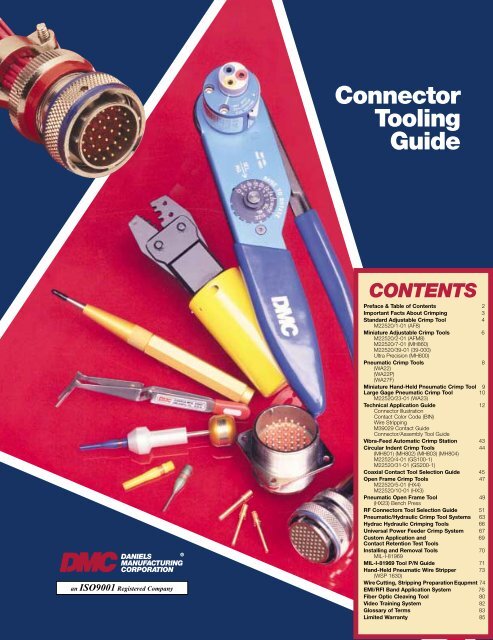
<strong>Connector</strong><strong>Tooling</strong><strong>Guide</strong>®DANIELSMANUFACTURINGCORPORATIONan ISO9001 Registered CompanyCONTENTSPreface & Table of Contents 2Important Facts About Crimping 3Standard Adjustable Crimp Tool 4M22520/1-01 (AF8)Miniature Adjustable Crimp Tools 6M22520/2-01 (AFM8)M22520/7-01 (MH860)M22520/39-01 (39-000)Ultra Precision (MH800)Pneumatic Crimp Tools 8(WA22)(WA22P)(WA27F)Miniature Hand-Held Pneumatic Crimp Tool 9Large Gage Pneumatic Crimp Tool 10M22520/23-01 (WA23)Technical Application <strong>Guide</strong> 12<strong>Connector</strong> IllustrationContact Color Code (BIN)Wire StrippingM39029 Contact <strong>Guide</strong><strong>Connector</strong>/Assembly Tool <strong>Guide</strong>Vibra-Feed Automatic Crimp Station 43Circular Indent Crimp Tools 44(MH801) (MH802) (MH803) (MH804)M22520/4-01 (GS100-1)M22520/31-01 (GS200-1)Coaxial Contact Tool Selection <strong>Guide</strong> 45Open Frame Crimp Tools 47M22520/5-01 (HX4)M22520/10-01 (HX3)Pneumatic Open Frame Tool 49(HX23) Bench PressRF <strong>Connector</strong>s Tool Selection <strong>Guide</strong> 51Pneumatic/Hydraulic Crimp Tool Systems 63Hydrac Hydraulic Crimping Tools 66Universal Power Feeder Crimp System 67Custom Application and 69Contact Retention Test ToolsInstalling and Removal Tools 70MIL-I-81969MIL-I-81969 Tool P/N <strong>Guide</strong> 71Hand-Held Pneumatic Wire Stripper 73(WSP 1630)Wire Cutting, Stripping Preparation Equpmnt 74EMI/RFI Band Application System 76Fiber Optic Cleaving Tool 80Video Training System 82Glossary of Terms 83Limited Warranty 85
PREFACE &TABLE OF CONTENTS®DANIELSMANUFACTURINGCORPORATIONDaniels tools have been utilized in militaryaircraft and aerospace programs for over50 years.By continuously planning and addingto our product lines, we are now fulfilling thedemands of other high technology fields suchas computers, lasers, communications, andmany other areas of electronic packaging.The people behind the DMC name arepleased to present our <strong>Connector</strong> AssemblyTools and Accessories on the pages thatfollow. We believe the application data whichaccompanies each section will answer yourspecific questions concerning tooling;however, we encourage you to contact us bytelephone or fax for the personal services ofour knowledgeable staff of applicationexperts.NOTICEANY PRICES WE QUOTE VERBALLY OR ANYPRICES APPEARING IN OUR PRINTED PRICE LISTSARE SUBJECT TO CHANGE WITHOUT PRIOR NOTICE.IF YOU NEED FIRM PRICES FOR FUTUREDELIVERIES YOU SHOULD REQUEST A WRITTENQUOTATION FROM OUR SALES OFFICE.WE ARE NOT LIABLE FOR CONSEQUENTIAL ORSPECIAL DAMAGES OF ANY NATURE OR KIND, RESULT-ING FROM THE USE OF ANY OF OUR PRODUCTS.DANIELS MANUFACTURING CORP.526 THORPE RD. • ORLANDO, FL 32824 U.S.A.PHONE 407/855-6161 • FAX 407-855-6884E-MAIL: DMC@DMCTOOLS.COM • WWW.DMCTOOLS.COMCONTENTSPreface & Table of Contents . . . . . . . . . . . . . . . . . . 2Important Facts About Crimping . . . . . . . . . . . . . . . 3Standard Adjustable Crimp Tool . . . . . . . . . . . . . . . 4M22520/1-01 (AF8)Miniature Adjustable Crimp Tools . . . . . . . . . . . . . . 6M22520/2-01 (AFM8)M22520/7-01 (MH860)M22520/39-01 (39-000)Ultra Precision (MH800)Pneumatic Crimp Tools . . . . . . . . . . . . . . . . . . . . . . 8(WA22)(WA22P)(WA27F)Miniature Hand-Held Pneumatic Crimp Tool. . . . . . 9Large Gage Pneumatic Crimp Tool . . . . . . . . . . . . 10M22520/23-01 (WA23)Technical Application <strong>Guide</strong>. . . . . . . . . . . . . . . . . . 12<strong>Connector</strong> IllustrationContact Color Code (BIN)Wire StrippingM39029 Contact <strong>Guide</strong><strong>Connector</strong>/Assembly Tool <strong>Guide</strong>Vibra-Feed Automatic Crimp Station. . . . . . . . . . . 43Circular Indent Crimp Tools . . . . . . . . . . . . . . . . . . 44(MH801) (MH802) (MH803) (MH804)M22520/4-01 (GS100-1)M22520/31-01 (GS200-1)Coaxial Contact Tool Selection <strong>Guide</strong> . . . . . . . . . . 45Open Frame Crimp Tools . . . . . . . . . . . . . . . . . . . . 47M22520/5-01 (HX4)M22520/10-01 (HX3)Pneumatic Open Frame Tool . . . . . . . . . . . . . . . . . 49(HX23) Bench PressRF <strong>Connector</strong>s Tool Selection <strong>Guide</strong>. . . . . . . . . . . 51Pneumatic/Hydraulic Crimp Tool Systems . . . . . . 63Hydrac Hydraulic Crimping Tools . . . . . . . . . . . . . 66Universal Power Feeder Crimp System. . . . . . . . . 67Custom Application and. . . . . . . . . . . . . . . . . . . . . 69Contact Retention Test ToolsInstalling and Removal Tools . . . . . . . . . . . . . . . . . 70MIL-I-81969MIL-I-81969 Tool P/N <strong>Guide</strong> . . . . . . . . . . . . . . . . . . 71Hand-Held Pneumatic Wire Stripper . . . . . . . . . . . 73(WSP 1630)Wire Cutting, Stripping Preparation Equipment . . 74EMI/RFI Band Application System. . . . . . . . . . . . . 76Fiber Optic Cleaving Tool . . . . . . . . . . . . . . . . . . . . 80Video Training System . . . . . . . . . . . . . . . . . . . . . . 82Glossary of Terms. . . . . . . . . . . . . . . . . . . . . . . . . . 83Limited Warranty . . . . . . . . . . . . . . . . . . . . . . . . . . 85FOR WARRANTY & LIMITATION OF LIABILITY INFORMATION SEE PAGE 85© COPYRIGHT 2003 DANIELS MANUFACTURING CORPORATION – 2126/01/REV 8
IMPORTANT FACTSABOUT CRIMPING®DANIELSMANUFACTURINGCORPORATIONCRIMPING: THEN AND NOWThe first multi-pin connectors wereterminated by soldering the conductorto non-removable contacts. However,high temperature applications andthe need for simple and reliable fieldservice led to the introduction ofconnectors with removable contacts.These were crimped onto the conductorrather than being soldered.The first standard crimp tooldeveloped to crimp these new contactswas introduced in the earlysixties. MS3191-1, a military drawing,defined this tool and its accessories.The MS3191-1 utilized a four indentcrimp pattern together with a positivestop locator which controlled the travelof the indenters (crimp depth).The MS3191-1 design was acompromise between simplicity ofoperation and crimp performancesince the crimp depth for any givencontact was not adjustable to accommodatethe differing diameters of theconductors to which it would becrimped. It was, however, suitable forthe crimp connectors of that era.An improved tool design featuringindependently adjustable crimp depthswas soon introduced as MS3191-4.The MS3191-4 had an internal adjustment,totally independent of the locator,which permitted the selection ofseven separate crimp depths, allowingoptimal crimping of conductors rangingfrom AWG 12 to 26 regardless ofthe wire barrel size of the contact.MS3191-4 also introduced theuse of the double tipped indenter toproduce an eight indent crimp patternwhich has consistently achievedsuperior tensile pull off values.MS3191-4 introduced the conceptof a turret head containing three locatorswhich could be used withoutseparating any of them from the basiccrimp tool.In 1969 two military specificationsfor crimp tools were developed toreplace the existing military drawings.They were MIL-T-22520C (Navy) andMIL-T-83724 (USAF) which defined astandard size crimp tool similar to theMS3191-4, but with an expandedeight step crimp depth range. Thesespecifications also defined a miniaturecrimp tool to crimp conductors assmall as AWG 32.Both documents were combinedin 1971 into MIL-C-22520D. Allprevious military standards for crimptools were then cancelled includingthe MS3191.MIL-C-22520 has since replacedmany other crimp tool documentsincluding: MS3198, MS22910,MS17776, MS28731, MS90388,MS14037, MS27437, MS27828,MS27832, MS55619, MS27426 andothers. This list includes specificationsfor indent crimp tools, terminal lugcrimp tools, pneumatic tools, coaxialcable crimp tools and connectorsservice kits.The establishment of MIL-C22520was a milestone on the road to crimptool standardization. Its developmenthas eliminated the waste and confusionwhich accompanied the overlappingapplications of many different“standard” crimp tools called out by adeluge of unrelated military drawings.MIL-C-22520D for the first timeestablished a single specification whichset forth performance requirements forall crimp tools to be used on militarystandard electrical connectors.THE CRIMPING CONCEPTCrimping is a method of firmlyattaching a terminal or contact end toan electrical conductor by pressureforming or reshaping a metal barreltogether with the conductor. Theforming of a satisfactory crimpdepends on the correct combinationof conductor, crimp barrel and tool.When applied with a properlymatched tool a union would beestablished which has both goodelectrical and mechanical characteristics.The tool will provide theserequirements consistently and reliablywith repeatability assured by qualitycycle controlled tooling. There areseveral common configurations ofcrimped joint; several examples areshown below.The electrical resistance of aproperly designed and controlledcrimped joint should be equal to, orless than, the resistance of an equalsection of wire. Specifications statethe requirements in terms of millivoltdrop at a designated current.The mechanical strength of acrimped joint and hence its pull-outforce (tensile strength), varies with thedeformation applied. Therefore, byproperly shaping the deformation ahigh pull-out force can be achieved,i.e. the crimp die of the tool determinesthe crimp configuration anddeformation.The dies in the tool determine thecompleted crimp configuration whichis generally an element of contactand/or connector design. Some of thedesign considerations are: a) The typeof contact, its size, shape material andfunction, b) The type and size of wiresto be accommodated, c) The type oftooling into which the configurationmust be built.EIGHT INDENTFOUR INDENTTWO INDENTHEXAGONAL CRIMPCIRCULAR CRIMPB CRIMPNEST & INDENT CRIMPCAPTIVE CRIMPINSULATION DISPLACEMENT© COPYRIGHT 2003 DANIELS MANUFACTURING CORPORATIONPAGE 3
STANDARD ADJUSTABLECRIMP TOOL®DANIELSMANUFACTURINGCORPORATIONUPPER RANGE CRIMPTOOL AF8 M22520/1-01The DMC AF8 qualified toMIL-DTL-22520/1, has virtually limitlessapplication within the specifiedwire range of 12 through 26 AWG.Over a thousand turret heads or positionersare available to adapt the toolframe to your specific military or proprietarycontact/wire combination. The 8impression crimp, which is standard inthe AF8, assures absolute maximumtensile strength with almost everyclosed barrel contact. In addition,special indent configurations are availableupon request.The precision ratchet controlscycling of the tool in both directions ofhandle movement. This assures thesame accurate crimp every time. It’slike having a quality control inspectorat every work station.Positive crimp depth is controlledby an 8 position selector knob convenientlylocated on the tool frame. Theoperator simply dials the desired stepfor the wire being used. This settingcan be secured by use of a locking pinor safety wire. The carefully engineereddesign achieves the absolute maximummechanical advantage; alongwith the tool’s light weight, operatorfatigue is minimized.The AF8 measures 9 3 ⁄4″ x 2 1 ⁄2″ x1 1 ⁄4″ approximately and weighs 15 oz.For proper operation the toolframe must be mated with one of thefollowing optional accessories: amilitary head (TH-XXX Part No. Series)a turret head (TM-XXX series), apositioner (TP-XXX series), or a universalhead (part No. UH2-5). This isdone simply by orienting the head inthe keyed position, and by tighteningthe hex socket screws provided aspart of the head.A permanent dataplate is affixedto all turret heads and positioners. Thisplate lists specific contact part numbers,the corresponding position colorcode (for 3 position turret heads), andsuggested selector depth settings forthe wire size being used.The universal head is ideally suitedfor lab work and prototype productionapplications. This head is attached inthe same manner as explained above.The selected contact is insertedthrough the entry hole on the oppositeside of the tool frame from the head.The height adjusting screw is thenrotated until the contact is in theproper position for crimping. Thescrew can be secured with the locknutprovided. The wire sizes listed on thetool frame selector knob can be usedas a reference starting point; however,some testing will be necessary todetermine the optimum selector settingfor your contact/wire combination.Periodic gaging is recommendedto insure accurate calibration. Thiscan be done easily by setting the toolselector knob to position #4, andchecking indenter closure withM22520/3-1 “GO/NO-GO” gage(DMC part no. G125).PAGE 4© COPYRIGHT 2003 DANIELS MANUFACTURING CORPORATION
®DANIELSMANUFACTURINGCORPORATIONOther than keeping the unit cleanand properly stored when not inservice, no operator maintenance isrequired. DMC offers complete factoryservice by knowledgeable technicianswithin a reasonable turnaround time.Complete instructions concerning theuse, care and warranty are suppliedwith each tool. Additional copies areavailable on request.MILITARY DMCP/N P/N DESCRIPTION NSNM22520/1-01 AF8 TOOL FRAME 5120-01-335-8571M22520/1-02 TH1A TURRET 5120-01-335-8834M22520/1-03 TH4 TURRET 5120-01-335-8835M22520/1-04 TH163 TURRET 5120-01-335-8836M22520/1-05 UH2-5 UNIVERSAL 5120-01-335-8583POSITIONERM22520/1-06 TP45 POSITIONER 5120-01-335-8584M22520/1-07 TP85 POSITIONER 5120-01-335-8585M22520/1-08 TH199S TURRET 5120-01-335-8837M22520/1-09 TP360 POSITIONER 5120-01-335-8586M22520/1-10 TP365 POSITIONER 5120-01-335-8587M22520/1-11 TP465 POSITIONER 5120-01-335-8588M22520/1-12 TH270 TURRET 5120-01-335-8838M22520/1-13 TH285 TURRET 5120-01-335-8839M22520/1-14 TH286 TURRET 5120-01-335-8840M22520/1-15 TP485 POSITIONER 5120-01-335-8589M22520/1-16 TP513 POSITIONER 5120-01-335-8590M22520/1-17 TP651 POSITIONER 5120-01-335-8591M22520/3-1 G125 GAGE 5220-00-165-7604© COPYRIGHT 2003 DANIELS MANUFACTURING CORPORATIONPAGE 5
MINIATURE ADJUSTABLECRIMP TOOLS®DANIELSMANUFACTURINGCORPORATION®LOWER RANGE CRIMPTOOL AFM8 M22520/2-01Qualified to MIL-DTL-22520/2, theDMC AFM8 is designed for most ofthe miniature and sub-miniature connectortypes that are so widely usedin all types of electronic systems.Originally developed for the Air Force,the AFM8 meets the need for a miniaturetool accommodating wire sizes 20through 32 AWG.The AFM8 gives a Mil-Standard 8impression crimp, which assuresmaximum tensile strength. The cyclecontrolled precision ratchet assuresconsistently accurate crimps everytime. The tool frame has a built-in 8step selector knob for ease in dialingthe correct crimp depth setting for thewire being used.Positioners adapt the tool frame toa particular application. The data plateon each positioner designates whichcontacts the positioner accommodatesfor its wire size and indicates selectorposition. Crimp depth is dialed on the8 step selector knob by merely raisingthe knob and rotating it to the properposition. The positioner is easilyremoved and changed.Periodic gaging is recommended toinsure accurate calibration. This is easilyaccomplished with the M22520/3-1“GO/NO-GO” gage (DMC part no.G125). The AFM8 is 6 3/4″ in lengthand weighs approximately 10 oz.Other than keeping the tool cleanand properly stored when not in use,no operator maintenance is required.DMC’s complete factory service isavailable. Complete instructions concerningthe use, care and warranty aresupplied with each tool. Additionalcopies are available from the factory.MILITARY DMCP/N P/N DESCRIPTION NSNM22520/2-01 AFM8 TOOL FRAME 5120-01-335-8572M22520/2-02 K1S POSITIONER 5120-01-335-8592M22520/2-03 K60S POSITIONER 5120-01-335-8593M22520/2-04 K151 POSITIONER 5120-01-335-8594M22520/2-05 K3 POSITIONER 5120-01-335-8595M22520/2-06 K41 POSITIONER 5120-01-335-8624M22520/2-07 K40 POSITIONER 5120-01-335-8625MILITARY DMCP/N P/N DESCRIPTION NSNM22520/2-08 K13-1 POSITIONER 5120-01-335-8626M22520/2-09 K42 POSITIONER 5120-01-335-8627M22520/2-10 K43 POSITIONER 5120-01-335-8628M22520/2-11 K287 POSITIONER 5120-01-335-8629M22520/2-12 K286 POSITIONER 5120-01-335-8630M22520/2-13 K338 POSITIONER 5120-01-335-8631M22520/2-14 K340 POSITIONER 5120-01-335-8632M22520/2-15 K341 POSITIONER 5120-01-335-8633M22520/2-16 K339 POSITIONER 5120-01-335-8634M22520/2-17 K342 POSITIONER 5120-01-335-8635M22520/2-18 K343 POSITIONER 5120-01-335-8636M22520/2-19 K330-2 POSITIONER 5120-01-335-8637M22520/2-20 K331-2 POSITIONER 5120-01-335-8638M22520/2-21 K332-2 POSITIONER 5120-01-335-8609M22520/2-22 K212 POSITIONER 5120-01-335-8610M22520/2-23 K267-1 POSITIONER 5120-01-335-8611M22520/2-24 K75S-1 POSITIONER 5120-01-335-8612M22520/2-25 K261-1 POSITIONER 5120-01-335-8613M22520/2-26 K262-1 POSITIONER 5120-01-335-8614M22520/2-27 K269-1 POSITIONER 5120-01-335-8615M22520/2-28 K373-1 POSITIONER 5120-01-335-8616M22520/2-29 K372-1 POSITIONER 5120-01-335-8617M22520/2-30 K404 POSITIONER 5120-01-335-8618M22520/2-31 K406 POSITIONER 5120-01-335-8619M22520/2-32 K496 POSITIONER 5120-01-335-8620M22520/2-33 K74S POSITIONER 5120-01-335-8621M22520/2-34 K323 POSITIONER 5120-01-335-8622M22520/2-35 K532-1 POSITIONER 5120-01-335-8623M22520/2-36 K473 POSITIONER 5120-01-335-8596M22520/3-1 G125 GAGE 5220-00-165-7604PAGE 6© COPYRIGHT 2003 DANIELS MANUFACTURING CORPORATION
®DANIELSMANUFACTURINGCORPORATIONULTRA PRECISION CRIMPTOOL (MODEL MH800)All DMC tools are designed andbuilt to the highest standards of precisionand quality, but some applicationscall for more. One such case is miniatureand subminiature contacts whichhave extremely thin wire barrel dimensions.The answer to this demand is themodel MH800 Ultra Precision CrimpTool which utilizes the same basiccomponents as the Model AFM8(M22520/2-01) Crimp Tool with tightergaging tolerances and a specialindenter tip configuration that assuresa uniform flow of metal during thecrimping operation.The model MH800 accommodateswire sizes 20 thru 32 AWG (the miniatureto sub-miniature range). It accommodatesthe K series or M22520/2-XXpositioners and is easily identified by adistinctive orange handle grip. It is thesame size and weight as model AFM8.Gaging is accomplished with the G100“GO/NO-GO” gage.MIDDLE RANGE CRIMPTOOL MH860 M22520/7-01Qualified to MIL-DTL-22520/7, theDMC MH860 is a recent addition tothe military specification. It wasdeveloped to meet the demonstratedneed for supporting the majority ofelectrical systems with one versatilecrimp tool frame.The MH860 accepts the entiremiddle wire range of 16 through 28AWG, with positioners which adapt itto virtually all applications consistentwith others in the MIL-DTL-22520family.MILITARY DMCP/N P/N DESCRIPTION NSNM22520/7-01 MH860 TOOL FRAME 5120-01-335-8573M22520/7-02 86-1S POSITIONER 5120-01-335-8597M22520/7-03 86-2 POSITIONER 5120-01-335-8598M22520/7-04 86-3 POSITIONER 5120-01-335-8599M22520/7-05 86-4 POSITIONER 5120-01-335-8600M22520/7-06 86-5 POSITIONER 5120-01-335-8601M22520/7-07 86-6 POSITIONER 5120-01-335-8602M22520/7-08 86-7 POSITIONER 5120-01-335-8603M22520/7-09 86-11S POSITIONER 5120-01-335-8604M22520/7-10 86-12S POSITIONER 5120-01-335-8605M22520/7-11 86-19 POSITIONER 5120-01-335-8606M22520/7-12 86-20 POSITIONER 5120-01-335-8607M22520/7-13 86-21 POSITIONER 5120-01-335-8608M22520/3-3 G145 GAGE 5120-00-338-0378THE MIL-C-28840 TOOLINGMIL-C-28840 connectors weredeveloped for the Navy, for use withjacketed cable in shipboard applications.They are a high density circularconnector series utilizing a high shockthreaded coupling system with frontrelease crimped contacts.For these connectors DMC hasadded a new crimping tool to itsrange, the M22520/34-01, and othertools as follows:MILITARY P/N DESCRIPTION DMC P/NM22520/34-01 BASIC CRIMP TOOL 39-000M22520/34-02 POSITIONER 39-102M22520/35 GAGE G345M81969/33-01 INST. TOOL (STRAIGHT) DAK55-22SAM81969/33-02 INST. TOOL (OFFSET) DAK55-22JAM81969-34-01 REMOVAL TOOL DRK56-22A© COPYRIGHT 2003 DANIELS MANUFACTURING CORPORATIONPAGE 7
PNEUMATICCRIMP TOOLS®DANIELSMANUFACTURINGCORPORATIONThe DMC Power Crimp toolsWA27F, WA22P and WA22 are directequivalents of their correspondinghand tools. They use the same turretheads or positioners, the gages andother accessories. As productionneeds grow, all that needs to beadded is the tool frame itself. Theresulting power capability can inmany instances compare with anautomated system costing thousandsof dollars more.These pneumatic tools are widelyused in both military and proprietaryprograms. Their popularity has comeabout in part because of theirunequaled reputation for trouble-free,dependable service and their costsaving and adaptability.Whether upper, middle or lowerrange, the power tools fulfill the sameprecise crimp requirements as thehand models. They use the sameindenter configuration, the same gagingdimensions and selector settings.No additional operator training isnecessary. Accurate calibration ismaintained by a unique 8 stepmachined steel block that holdsgaging tolerances far longer than theusual adjustment screw method. Thissolid gaging means high output withless downtime.The compact size and light weightof these tools allows them to be usedeasily as hand tools, as well as highproduction bench tools. The handtrigger is designed for equal ease ofuse by right or left handed operators.Bench mounted, the optional footvalve allows hands-free operation. Thebench mount will allow the tool to besecured at virtually any angle for individualcomfort, thereby minimizingoperator fatigue.The foot valve, when installedin-line with an air supply, makes aportable system which is adaptable toany work bench. Air supply requirementsare 80-120 PSI (5.5 to 8.0atmospheres) clean dry air. The systemuses standard air fittings readilyavailable in most shops.UPPER RANGE WA27F(EQUIVALENT TO AF8)accommodates TH-XXXMIL-STDheads. TH-XXX series turret heads orTP-XXX series positioners, length 10″,diameter 2 3/4″, weight 50 oz.MIDDLE RANGE WA22P(EQUIVALENT TO MH860)accommodates 86-XXX seriespositioners, length 8″, diameter 2 1/4″,weight 32 oz.LOWER RANGE WA22(EQUIVALENT TO AFM8)accommodates K series positioners,length 8″, diameter 2 1/4″,weight 32 oz.BENCH MOUNT BM-2FOOT VALVE WA10PAGE 8© COPYRIGHT 2003 DANIELS MANUFACTURING CORPORATION
© COPYRIGHT 2003 DANIELS MANUFACTURING CORPORATIONPAGE 9
LARGE GAGEPNEUMATIC CRIMP TOOLS®DANIELSMANUFACTURINGCORPORATIONWA23 PNEUMATICCRIMP TOOLDMC’s heavy pneumatic crimptool functions with the push of abutton for operator ease. This heavyduty crimp tool accommodates largesize contacts 8 through 0000 (AWG)and operates on standard 90-125 psi(5.4-8.16 BAR) shop air sources.It is engineered with the operator’ssafety in mind and features a full cyclecontrol system. This tool is portableand needs no extra booster for largesize contacts.The standard die assembly andlocator are easily interchangeable withno special tool required. Custom diesand locators may be designed tospecific requirements. An optional footvalve is available upon request.NOW FEATURING…Die Assembliesand Locators for:• Pre-Installed and Un-InsulatedRing Terminals for Military andCommercial Applications(MS25036, MS20659,MIL-T-7928)M22520/23 Tool, Dieand Locator ListMIL # DESCRIPTION DMC #M22520/23-01 Crimp Tool WA23M22520/23-02 Die Assy. 8 WA23-2M22520/23-03 Die Assy. 6 WA23-3M22520/23-04 Die Assy. 4 WA23-4M22520/23-05 Die Assy. 1/0 WA23-5M22520/23-06 Die Assy. 2/0 WA23-6M22520/23-07 Die Assy. 4/0 WA23-7M22520/23-09 Locator 8 WA23-9M22520/23-10 Locator 6 WA23-10M22520/23-11 Locator 4 WA23-11M22520/23-12 Locator 4, 4N, 4G WA23-12M22520/23-13 Locator 1/0 WA23-13M22520/23-14 Locator 1/0, 1/0N WA23-14M22520/23-15 Locator 2/0, 2/0N WA23-15M22520/23-16 Locator 4/0, 4/0N WA23-16CONTACTGAGEP/N SIZE “GO” “NO-GO” P/NM22520/23-02 8 .130 .136 G693M22520/23-03 6 .171 .178 G694M22520/23-04 4 .195 .202 G695M22520/23-05 0 .325 .332 G695M22520/23-06 00 .351 .358 G697M22520/23-07 0000 .425 .432 G698PAGE 10© COPYRIGHT 2003 DANIELS MANUFACTURING CORPORATION
LARGE GAGE CONTACTAPPLICATION INFORMATION®DANIELSMANUFACTURINGCORPORATION®CONTACT APPLICATION CROSS REFERENCEMIL-C-5015 Front Release (3400 Series)CONTACT BIN TYPE DIEPART # CODE P/S SIZE ASSEMBLY LOCATORM39029/44 291 P 8 WA23-2 WA23-9M39029/45 298 S 8 WA23-2 WA23-9M39029/44 292 P 4 WA23-4 WA23-11M39029/45 299 S 4 WA23-4 WA23-11M39029/44 293 P 0 WA23-5 WA23-13M39029/45 300 S 0 WA23-5 WA23-13MIL-C-5015 Rear Release (3450 Series)M39029/29 214 P 8 WA23-2 WA23-9M39029/30 220 S 8 WA23-2 WA23-9M39029/29 215 P 4 WA23-4 WA23-11M39029/30 221 S 4 WA23-4 WA23-11M39029/29 216 P 0 WA23-5 WA23-13M39029/30 222 S 0 WA23-5 WA23-13MIL-C-22992 Class LHeavy Duty Cylindrical <strong>Connector</strong>M39029/48 317 P 6 WA23-3 WA23-10M39029/48 318 P 6N WA23-3 WA23-10M39029/48 319 P 6G WA23-3 WA23-10M39029/49 329 S 6 WA23-3 WA23-10M39029/49 330 S 6G WA23-3 WA23-10M39029/48 320 P 4 WA23-4 WA23-12M39029/48 321 P 4N WA23-4 WA23-12M39029/48 322 P 4G WA23-4 WA23-12M39029/49 331 S 4 WA23-4 WA23-12M39029/49 332 S 4G WA23-4 WA23-12M39029/48 323 P 1/0 WA23-5 WA23-14M39029/48 324 P 1/0N WA23-5 WA23-14M39029/49 333 S 1/0 WA23-5 WA23-14M39029/48 325 P 2/0 WA23-6 WA23-15M39029/48 326 P 2/0N WA23-6 WA23-15M39029/49 334 S 2/0 WA23-6 WA23-15M39029/48 327 P 4/0 WA23-7 WA23-16M39029/48 328 P 4/0N WA23-7 WA23-16M39029/49 335 S 4/0 WA23-7 WA23-16J-Tech541-220-0808 214 P 8 WA23-2 WA23-9541-220-0404 215 P 4 WA23-4 WA23-11542-220-0808 220 S 8 WA23-2 WA23-9542-220-0404 221 S 4 WA23-4 WA23-11Amphenol/Bendix10-497100-6 317 P 6 WA23-3 WA23-1010-497102-6 318 P 6N WA23-3 WA23-1010-497222-6 319 P 6 WA23-3 WA23-1010-497100-4 320 P 4 WA23-4 WA23-1210-497102-4 321 P 4N WA23-4 WA23-1210-497222-4 322 P 4G WA23-4 WA23-1210-497100-3 323 P 1/0 WA23-5 WA23-1410-497102-3 324 P 1/0N WA23-5 WA23-1410-497100-43 327 P 4/0 WA23-7 WA23-1610-497102-43 328 P 4/0N WA23-7 WA23-1610-497101-6 329 S 6 WA23-3 WA23-1010-497223-6 330 S 6G WA23-3 WA23-1010-497101-4 331 S 4 WA23-4 WA23-1210-497223-4 332 S 4G WA23-4 WA23-1210-497101-3 333 S 1/0 WA23-5 WA23-1410-497101-43 335 S 4/0 WA23-7 WA23-16© COPYRIGHT 2003 DANIELS MANUFACTURING CORPORATIONBurndy Corporation (FCI)CONTACT BIN TYPE DIEPART # CODE P/S SIZE ASSEMBLY LOCATORB559-01-3 318 P 6N WA23-3 WA23-10B559-01-6 319 P 6 WA23-3 WA23-10B559-01-1 320 P 4 WA23-4 WA23-12B559-01-2 321 P 4N WA23-4 WA23-12B559-01-10 322 P 4G WA23-4 WA23-12B559-01-4 323 P 1/0 WA23-5 WA23-14B559-01-5 324 P 1/0N WA23-5 WA23-14B559-01-8 327 P 4/0 WA23-7 WA23-16B559-01-9 328 P 4/0N WA23-7 WA23-16B560-01-2 329 S 6 WA23-3 WA23-10B560-01-4 330 S 6G WA23-3 WA23-10B560-01-1 331 S 4 WA23-4 WA23-12B560-01-6 322 S 4G WA23-5 WA23-14B560-01-3 333 S 1/0 WA23-5 WA23-14B560-01-5 335 S 4/0 WA23-7 WA23-16ITT Cannon030-3198-003 214 P 8 WA23-2 WA23-9030-3199-004 215 P 4 WA23-4 WA23-11030-3200-003 216 P 0 WA23-5 WA23-13031-3116-003 220 S 8 WA23-2 WA23-9031-3117-003 221 S 4 WA23-4 WA23-11031-3118-003 222 S 0 WA23-5 WA23-13Matrix Science/AMP-TYCO5000-029-0008 214 P 8 WA23-2 WA23-95000-029-0004 215 P 4 WA23-4 WA23-115000-029-0000 216 P 0 WA23-5 WA23-135100-033-0008 220 S 8 WA23-2 WA23-95100-033-0004 221 S 4 WA23-4 WA23-115100-033-0000 222 S 0 WA23-5 WA23-13Tri-Star916-0808-093 214 P 8 WA23-2 WA23-9916-0404-094 215 P 4 WA23-4 WA23-11916-0000-095 216 P 0 WA23-5 WA23-13915-0808-093 220 S 8 WA23-2 WA23-9915-0404-094 221 S 4 WA23-4 WA23-11915-0000-095 222 S 0 WA23-5 WA23-13915-0606-595 317 P 6 WA23-3 WA23-10915-0606-596 318 P 6N WA23-3 WA23-10915-0606-597 319 P 6G WA23-3 WA23-10915-0404-576 320 P 4 WA23-4 WA23-12915-0404-577 321 P 4N WA23-4 WA23-12915-0404-578 322 P 4G WA23-4 WA23-12915-1001-498 323 P 1/0 WA23-5 WA23-14915-1001-499 324 P 1/0N WA23-5 WA23-14915-2020-579 325 P 2/0 WA23-6 WA23-15915-2020-580 326 P 2/0N WA23-6 WA23-15915-4040-598 327 P 4/0 WA23-7 WA23-16915-4040-599 328 P 4/0N WA23-7 WA23-16916-0606-595 329 S 6 WA23-3 WA23-10916-0606-597 330 S 6G WA23-3 WA23-10916-0404-576 331 S 4 WA23-4 WA23-12916-0404-578 332 S 4G WA23-4 WA23-12916-1001-498 333 S 1/0 WA23-5 WA23-14916-2020-579 334 S 2/0 WA23-6 WA23-15916-4040-598 335 S 4/0 WA23-7 WA23-16Cross reference information was compiled from (QPL) Qualified Products Listing.Additional tooling is available for other die, locator and wire size applications.PAGE 11
TECHNICAL APPLICATION GUIDETYPICAL COMPLEX CABLE CONNECTORA. Wire SealB. Socket ContactC. Chamfered Socket Lead-InE. Pin ContactF. Contact Retention ClipG. Interfacial SealD. Peripheral O-Ring SealCONTACT COLOR CODE AND BIN*0 – Black1 – Brown2 – Red3 – Orange4 – Yellow5 – Green6 – Blue7 – Violet8 – Gray9 – White*BASIC IDENTIFICATION NUMBERManufacturers have the option of identifyingcontacts by stamping the bin code on theshoulder or the wire barrel.WIRE STRIPPING TECHNIQUE1. Determine the proper length of insulation to be removed. Wire must be visiblein inspection hole. Insulation must be 1/64″ – 1/32″ from end of contact orinside of insulation cup.2. Insert wire into exact center of correct cutting slot for wire size to be stripped.Each slot is marked with wire size.3. Close handles together as close as possible.4. Release handles, allowing wire holder to return to open position.5. Remove stripped wire.6. After stripping, strands of wire should be twisted firmly together in the samedirection as the normal lay of the wire.7. Stripped wire with nicked or cut strands is not acceptable.IMPORTANT NOTICE – The tooling listed in the technical application guides of this catalog and other DMC publications represents datawhich has been compiled over many years of product use and application. Some tooling suggested herein may or may not cover auser’s specific contract or manufacturing requirements. It is the user’s responsibility to carry out sufficient testing to verify suitability ofthe specific DMC product selected for the specific requirements of each particular application.PAGE 12© COPYRIGHT 2003 DANIELS MANUFACTURING CORPORATION
TECHNICAL APPLICATION GUIDEM39029 CONTACT QUICK LOCATION CHARTCONTACTPARTNUMBERPAGENUMBERCONTACTPARTNUMBERPAGENUMBERCONTACTPARTNUMBERPAGENUMBERCONTACTPARTNUMBERPAGENUMBERM39029/1 41M39029/27 40M39029/56 23, 24, 25M39029/87 Call DMCM39029/2 33M39029/28 40M39029/57 15, 24, 26M39029/88 Call DMCM39029/3 33M39029/29 28, 37M39029/58 15, 23, 24, 25M39029/89 Call DMCM39029/4 17, 36, 38, 39M39029/30 28, 37M39029/59 40M39029/90 Call DMCM39029/5 17, 36, 38, 39M39029/31 16, 18, 19, 21, 35M39029/60 40M39029/91 Call DMCM39029/6 39M39029/32 16, 18, 19, 21, 35M39029/63 15M39029/92 Call DMCM39029/7 39M39029/33 29M39029/64 15M39029/93 Call DMCM39029/8 39M39029/34 20M39029/65 Call DMCM39029/94 Call DMCM39029/9 Call DMCM39029/35 20M39029/66 Call DMCM39029/95 Call DMCM39029/10 Call DMCM39029/36 20M39029/68 Call DMCM39029/96 Call DMCM39029/11 34M39029/37 20M39029/69 40M39029/97 Call DMCM39029/12 34M39029/38 Call DMCM39029/70 40M39029/98 Call DMCM39029/13 39M39029/40 Call DMCM39029/71 Call DMCM39029/99 Call DMCM39029/14 39M39029/41 Call DMCM39029/72 Call DMCM39029/100 Call DMCM39029/15 Call DMCM39029/42 Call DMCM39029/73 Call DMCM39029/101 Call DMCM39029/16 32M39029/43 Call DMCM39029/74 Call DMCM39029/102 Call DMCM39029/17 31M39029/44 27M39029/75 40M39029/103 Call DMCM39029/18 31M39029/45 27M39029/76 40M39029/104 Call DMCM39029/19 39M39029/46 30M39029/77 40M39029/105 Call DMCM39029/20 39M39029/47 29, 30M39029/78 40M39029/106 Call DMCM39029/21 39M39029/48 14M39029/79 Call DMCM39029/107 Call DMCM39029/22 31, 32, 42M39029/49 14M39029/80 Call DMCM39029/108 Call DMCM39029/23 Call DMCM39029/50 40M39029/83 22M39029/109 Call DMCM39029/24 Call DMCM39029/51 40M39029/84 22M39029/25 40M39029/54 40M39029/85 Call DMCM39029/26 40M39029/55 40M39029/86 Call DMCRefer to Technical Application <strong>Guide</strong> (Pages 14–42)© COPYRIGHT 2003 DANIELS MANUFACTURING CORPORATIONPAGE 13
MIL-C-22992CLASS LCIRCULARHEAVY DUTYFRONT RELEASE CONTACTSCONNECTORPART NUMBER DESCRIPTION SOURCESMS90555WALL MOUNT RECEPTACLEMS90556 STRAIGHT PLUG AMPHENOL CORP.MS90557 IN-LINE RECEPTACLE ITT CANNONMS90558WALL MOUNT PLUGSIZE (AWG)MATING WIRE PART NUMBER* PART NUMBER WIRECONTACTS END BARREL PIN/SOC. (CURRENT) (SUPERSEDED) RANGETYPICAL CONTACTCONFIGURATION6 6 P M39029/48-317 MS90559-11 66N 6 P M39029/48-318 MS90559-12 66G 6 P M39029/48-319 MS90559-14 66 6 S M39029/49-329 MS90560-7 66G 6 S M39029/49-330 MS90560-8 64 4 P M39029/48-320 MS90559-8 44N 4 P M39029/48-321 MS90559-9 44G 4 P M39029/48-322 MS90559-13 44 4 S M39029/49-331 MS90560-5 44G 4 S M39029/49-332 MS90560-9 40 0 P M39029/48-323 MS90559-5 00N 0 P M39029/48-324 MS90559-6 00 0 S M39029/49-333 MS90560-3 02/0 2/0 P M39029/48-325 MS90559-3 2/02/0N 2/0 P M39029/48-326 MS90559-3 2/02/0 2/0 S M39029/49-334 MS90560-2 2/04/0 4/0 P M39029/48-327 MS90559-1 4/04/0N 4/0 P M39029/48-328 MS90559-2 4/04/0 4/0 S M39029/49-335 MS90560-1 4/0TOOL SELECTION CRIMP TOOL AND ACCESSORY ASSEMBLY TOOLSBIN* COLOR AF8 AFM8 MH860 WA23 (POS) WA23 (DIE) INSTALLING REMOVAL317 ORANGE-BROWN-VIOLET WA23-10 WA23-3 — DRK178-6A318 ORANGE-BROWN-GRAY WA23-10 WA23-3 DRK178-6A319 ORANGE-BROWN-WHITE WA23-10 WA23-3 DRK178-6A329 ORANGE-RED-WHITE WA23-10 WA23-3 DRK178-6A330 ORANGE-ORANGE-BLACK WA23-10 WA23-3 — DRK178-6A320 ORANGE-RED-BLACK WA23-12 WA23-4 DRK178-5A321 ORANGE-RED-BROWN WA23-12 WA23-4 DRK178-5A322 ORANGE-RED-RED WA23-12 WA23-4 DRK178-5A331 ORANGE-ORANGE-BROWN WA23-12 WA23-4 DRK178-5A332 ORANGE-ORANGE-RED WA23-12 WA23-4 DRK178-5A323 ORANGE-RED-ORANGE WA23-14 WA23-5 — DRK178-3A324 ORANGE-RED-YELLOW WA23-14 WA23-5 DRK178-3A333 ORANGE-ORANGE-ORANGE WA23-14 WA23-5 DRK178-3A325 ORANGE-RED-GREEN WA23-15 WA23-6 — DRK178-2A326 ORANGE-RED-BLUE WA23-15 WA23-6 DRK178-2A334 ORANGE-ORANGE-YELLOW WA23-15 WA23-6 DRK178-2A327 ORANGE-RED-VIOLET WA23-16 WA23-7 DRK178-1A328 ORANGE-RED-GRAY WA23-16 WA23-7 — DRK178-1A335 ORANGE-ORANGE-GREEN WA23-16 WA23-7 DRK178-1A*The three number suffix on M39029 series contacts is referred to as a “BIN” code and contact color stripes to determine the correct tool part numbers.PAGE 14© COPYRIGHT 2003 DANIELS MANUFACTURING CORPORATION
MIL-C-24308MINIATURE RECTANGULARRACK & PANELREAR RELEASE CONTACTSCONNECTORPART NUMBER DESCRIPTION SOURCESADI ELECTRONICS INC.AMPHENOL CORP.CW INDUSTRIESM24308/2 POLARIZED SHELL SOCKET CONTACTS CINCH CONNECTORM24308/4 POLARIZED SHELL PIN CONTACTS CRISTEK INTERCONNECTS INC.M24308/6 POLARIZED SHELL SOCKET CONTACTS NON-MAGNETIC FCI FRAMATONE GROUPM24038/8 POLARIZED SHELL PIN CONTACTS NON-MAGNETIC GENERAL CONNECTOR CORP.GLASSEAL PRODUCTS INC.ITT CANNONPOSITRONIC INDUSTRIES INC.TYCO ELECTRONICSSIZE (AWG)MATING WIRE PART NUMBER* PART NUMBER WIRECONTACTS END BARREL PIN/SOC. (CURRENT) (SUPERSEDED) RANGE20 20 P M39029/64-369 M24308/11-1 20-2420 20 S M39029/63-368 M24308/10-1 20-2422 22D P M39029/58-360 M24308/13-1 22-2822 22D S M39029/57-354 M24308/12-1 22-28TYPICAL CONTACTCONFIGURATIONTOOL SELECTION CRIMP TOOL AND ACCESSORY ASSEMBLY TOOLSBIN* COLOR AF8 AFM8 MH860 WA23 (POS) WA23 (DIE) INSTALLING REMOVAL369 ORANGE-BLUE-WHITE TP585 K13-1 86-30-1 DAK145 or M81969/1-02 DRK145 or M81969/1-02368 ORANGE-BLUE-GRAY TP585 K13-1 86-30-1 DAK145 or M81969/1-02 DRK145 or M81969/1-02360 ORANGE-BLUE-BLACK K42 86-6 DAK95-22MB or M81969/1-04 DRK95-22MB or M81969/1-04354 ORANGE-GREEN-YELLOW K41 86-5 DAK95-22MB or M81969/1-04 DRK95-22MB or M81969/1-04*The three number suffix on M39029 series contacts is referred to as a “BIN” code and contact color stripes to determine the correct tool part numbers.© COPYRIGHT 2003 DANIELS MANUFACTURING CORPORATIONPAGE 15
MIL-C-26482SERIES 1CIRCULARBAYONET COUPLINGFRONT RELEASE CONTACTSCONNECTORPART NUMBER DESCRIPTION SOURCESMS3120WALL MOUNT FLANGE RECEPTACLEMS3121 CABLE CONNECTING PLUG AMPHENOL CONNECTORSMS3122 BOX MOUNT FLANGE RECEPTACLE ARRAY CONNECTORS CORP.MS3124 JAM NUT REAR MOUNT RECEPTACLE FCI FRAMATONE GROUPMS3126 STRAIGHT PLUG ITT CANNON – ITT CANNON MEXICOMS3127 BOX MOUNT FLANGE RECEPTACLE VEAMMS3128WALL MOUNT FLANGE RECEPTACLESIZE (AWG)MATING WIRE PART NUMBER* PART NUMBER WIRECONTACTS END BARREL PIN/SOC. (CURRENT) (SUPERSEDED) RANGE12 12 P M39029/31-234 MS3192-12-12A 12-1412 12 S M39029/32-253 MS3193-12-12A 12-1416 16 P M39029/31-228 MS3192-16-16A 16-2016 16 S M39029/32-247 MS3193-16-16A 16-2020 20 P M39029/31-240 MS3192-20A-20A 20-2420 20 S M39029/32-259 MS3193-20A-20A 20-24TYPICAL CONTACTCONFIGURATIONTOOL SELECTION CRIMP TOOL AND ACCESSORY ASSEMBLY TOOLSBIN* COLOR AF8 AFM8 MH860 WA23 (POS) WA23 (DIE) INSTALLING REMOVAL234 RED-ORANGE-YELLOW TH1A DAK12B DRK12B253 RED-GREEN-ORANGE TH1A DAK12B DRK12B228 RED-RED-GRAY TH1A 86-2 DAK16B DRK16B247 RED-YELLOW-VIOLET TH1A 86-2 DAK16B DRK16B240 RED-YELLOW-BLACK TH1A K1S 86-1S DAK20B DRK20B259 RED-GREEN-WHITE TH1A K1S 86-1S DAK20B DRK20B*The three number suffix on M39029 series contacts is referred to as a “BIN” code and contact color stripes to determine the correct tool part numbers.PAGE 16© COPYRIGHT 2003 DANIELS MANUFACTURING CORPORATION
MIL-C-26482SERIES 2CIRCULARBAYONET COUPLINGREAR RELEASE CONTACTSCONNECTORPART NUMBER DESCRIPTION SOURCESMS3470 WALL MOUNT FLANGE RECEPTACLE AERO ELECTRONIC CONNECTOR, INC.MS3471 CABLE CONNECTING RECEPTACLE AMPHENOL CONNECTORSMS3472 WIDE FLANGE WALL MOUNT RECEPTACLE DEUTSCHMS3474 JAM NUT RECEPTACLE FCI FRAMATONE GROUPMS3475 PLUG RFI ITT CANNONMS3476 STRAIGHT PLUG HERMETIC SEAL CORPORATIONSIZE (AWG)MATING WIRE PART NUMBER* PART NUMBER WIRECONTACTS END BARREL PIN/SOC. (CURRENT) (SUPERSEDED) RANGETYPICAL CONTACTCONFIGURATION12 12 P M39029/4-113 M39029/4-12-12 12-1412 12 S M39029/5-118 M39029/5-12-12 12-1412 16 P M39029/4-114 M39029/4-12-16 16-2012 16 S M39029/5-119 M39029/5-12-16 16-2016 16 P M39029/4-111 M39029/4-16-16 16-2016 16 S M39029/5-116 M39029/5-16-16 16-2016 20 P M39029/4-112 M39029/4-16-20 20-2416 20 S M39029/5-117 M39029/5-16-20 20-2420 20 P M39029/4-110 M39029/4-20-20 20-2420 20 S M39029/5-115 M39029/5-20-20 20-24TOOL SELECTION CRIMP TOOL AND ACCESSORY ASSEMBLY TOOLSBIN* COLOR AF8 AFM8 MH860 WA23 (POS) WA23 (DIE) INSTALLING REMOVAL113 BROWN-BROWN-ORANGE TH1A DAK83-12B DRK83-12B118 BROWN-BROWN-GRAY TH1A DAK83-12B DRK83-12B114 BROWN-BROWN-YELLOW TH1A 86-2 DAK83-12B DRK83-12B119 BROWN-BROWN-WHITE TH1A 86-2 DAK83-12B DRK83-12B111 BROWN-BROWN-BROWN TH1A 86-2 DAK83-16B DRK83-16B116 BROWN-BROWN-BLUE TH1A 86-2 DAK83-16B DRK83-16B112 BROWN-BROWN-RED TH1A K1S 86-2 DAK83-16B DRK83-16B117 BROWN-BROWN-VIOLET TH1A K1S 86-2 DAK83-16B DRK83-16B110 BROWN-BROWN-BLACK TH1A K1S 86-1S DAK83-20B DRK83-20B115 BROWN-BROWN-GREEN TH1A K1S 86-1S DAK83-20B DRK83-20B*The three number suffix on M39029 series contacts is referred to as a “BIN” code and contact color stripes to determine the correct tool part numbers.© COPYRIGHT 2003 DANIELS MANUFACTURING CORPORATIONPAGE 17
MIL-C-26500CIRCULARTHREADED OR BAYONET COUPLINGFRONT RELEASE CONTACTSCONNECTORPART NUMBER DESCRIPTION SOURCESMS24264 FLANGE MOUNT RECEPTACLE PLYE-NATIONAL CONNECTORSMS24265 SINGLE HOLE MOUNT RECEPTACLE AERO ELECTRIC CONNECTOR, INC.MS24266 STRAIGHT PLUG RMS COMPANYMS27613 WALL MOUNT RECEPTACLE CINCH CONNECTOR DIVISIONMS27614 JAM NUT AMPHENOL CONNECTORSMS27615 PLUG HERMETIC SEAL CORPORATIONAMERICAN MICRO PRODUCTS, INC.SIZE (AWG)MATING WIRE PART NUMBER* PART NUMBER WIRECONTACTS END BARREL PIN/SOC. (CURRENT) (SUPERSEDED) RANGETYPICAL CONTACTCONFIGURATION12 12 P M39029/31-235 MS24254-12P 12-1412 12 S M39029/32-254 MS24255-12S 12-1416 16 P M39029/31-229 MS24254-16P 16-2016 16 S M39029/32-248 MS24255-16S 16-2020 20 P M39029/31-241 MS24254-20P 20-2420 20 S M39029/32-260 MS24255-20S 20-24TOOL SELECTION CRIMP TOOL AND ACCESSORY ASSEMBLY TOOLSBIN* COLOR AF8 AFM8 MH860 WA23 (POS) WA23 (DIE) INSTALLING REMOVAL235 RED-ORANGE-GREEN TH1A DAK12B DRK12B254 RED-GREEN-YELLOW TH1A DAK12B DRK12B229 RED-RED-WHITE TH1A 86-2 DAK16B DRK16B248 RED-YELLOW-GRAY TH1A 86-2 DAK16B DRK16B241 RED-YELLOW-BROWN TH1A K1S 86-1S DAK20B DRK20B260 RED-BLUE-BLACK TH1A K1S 86-1S DAK20B DRK20B*The three number suffix on M39029 series contacts is referred to as a “BIN” code and contact color stripes to determine the correct tool part numbers.PAGE 18© COPYRIGHT 2003 DANIELS MANUFACTURING CORPORATION
MIL-C-26518CLASS RMINIATURE RECTANGULARRACK AND PANELFRONT RELEASE CONTACTSCONNECTORPART NUMBER DESCRIPTION SOURCESM24285M24286RECEPTACLEPLUGAMPHENOL CONNECTORSSIZE (AWG)MATING WIRE PART NUMBER* PART NUMBER WIRECONTACTS END BARREL PIN/SOC. (CURRENT) (SUPERSEDED) RANGETYPICAL CONTACTCONFIGURATION12 12 P M39029/31-235 MS24254-12P 12-1412 12 S M39029/32-254 MS24255-12S 12-1416 16 P M39029/31-229 MS24254-16P 16-2016 16 S M39029/32-248 MS24255-16S 16-2020 20 P M39029/31-241 MS24254-20P 20-2420 20 S M39029/32-260 MS24255-20S 20-24TOOL SELECTION CRIMP TOOL AND ACCESSORY ASSEMBLY TOOLSBIN* COLOR AF8 AFM8 MH860 WA23 (POS) WA23 (DIE) INSTALLING REMOVAL235 RED-ORANGE-GREEN TH1A DAK12B DRK12B254 RED-GREEN-YELLOW TH1A DAK12B DRK12B229 RED-RED-WHITE TH1A 86-2 DAK16B DRK16B248 RED-YELLOW-GRAY TH1A 86-2 DAK16B DRK16B241 RED-YELLOW-BROWN TH1A K1S 86-1S DAK20B DRK20B260 RED-BLUE-BLACK TH1A K1S 86-1S DAK20B DRK20B*The three number suffix on M39029 series contacts is referred to as a “BIN” code and contact color stripes to determine the correct tool part numbers.© COPYRIGHT 2003 DANIELS MANUFACTURING CORPORATIONPAGE 19
MIL-C-28748RECTANGULARRACK AND PANELCONNECTORPART NUMBER DESCRIPTION SOURCESM28748/3 PIN CONTACTS SIZE 16 & 20 CONTINENTAL CONNECTOR CO.M28748/4 SKT CONTACTS SIZE 16 & 20 POSITRONIC INDUSTRIES, INC.M28748/9 PIN CONTACTS 16 POLARIZED CENTER SCREW LOCK WINCHESTER ELECTRONICSM278748/10 SKT CONTACTS 16 POLARIZED CENTER SCREW LOCK DELPHI CONNECTION SYSTEMSM28748/13 PIN CONTACTS 22 J-TECH, INC.M28748/14 SKT CONTACTS 22SIZE (AWG)MATING WIRE PART NUMBER* PART NUMBER WIRECONTACTS END BARREL PIN/SOC. (CURRENT) (SUPERSEDED) RANGETYPICAL CONTACTCONFIGURATION16 16 P M39029/36-278 MS17807-16-16 16-2016 16 S M39029/37-280 MS17808-16-16 16-2016 20 P M39029/36-277 MS17807-16-20 20-2416 20 S M39029/37-279 MS17808-16-20 20-2416 16 P M39029/34-273 MS17803-16-16 16-2016 16 S M39029/35-276 MS17804-16-16 16-2016 20 P M39029/34-272 MS17803-16-20 20-2416 20 S M39029/35-275 MS17804-16-20 20-2420 20 P M39029/34-271 MS17803-20-20 20-2420 20 S M39029/35-274 MS17804-20-20 20-2422 22 P M39029/34-440 M39029/34-22-22 22-2622 22 S M39029/35-441 M39029/35-22-22 22-26TOOL SELECTION CRIMP TOOL AND ACCESSORY ASSEMBLY TOOLSBIN* COLOR AF8 AFM8 MH860 WA23 (POS) WA23 (DIE) INSTALLING REMOVAL278 RED-VIOLET-GRAY TH4 DAK123A DRK124A280 RED-GRAY-BLACK TH4 DAK123A DRK124A277 RED-VIOLET-VIOLET TH4 DAK123A DRK124A279 RED-VIOLET-WHITE TH4 DAK123A DRK124A273 RED-VIOLET-ORANGE TH4 86-146 DAK123A DRK124A276 RED-VIOLET-BLUE TH4 86-146 DAK123A DRK124A272 RED-VIOLET-RED TH4 86-146 DAK123A DRK124A275 RED-VIOLET-GREEN TH4 86-146 DAK123A DRK124A271 RED-VIOLET-BROWN TH4 86-146 DAK123A DRK124A274 RED-VIOLET-YELLOW TH4 86-146 DAK123A DRK124A440 YELLOW-YELLOW-BLACK K280 DAK123A-22A DAK124A-22A441 YELLOW-YELLOW-BROWN K280 DAK123A-22A DAK124A-22A*The three number suffix on M39029 series contacts is referred to as a “BIN” code and contact color stripes to determine the correct tool part numbers.PAGE 20© COPYRIGHT 2003 DANIELS MANUFACTURING CORPORATION
MIL-C-38300CIRCULARTHREADED OR BAYONET COUPLINGFRONT RELEASE CONTACTSCONNECTORPART NUMBER DESCRIPTION SOURCESMS24264FLANGE MOUNT RECEPTACLEMS24265 SINGLE HOLE MOUNT RECEPTACLE NO QPL SOURCESMS24266STRAIGHT PLUGSIZE (AWG)MATING WIRE PART NUMBER* PART NUMBER WIRECONTACTS END BARREL PIN/SOC. (CURRENT) (SUPERSEDED) RANGE16 16 P M39029/31-229 MS24254-16P 16-2016 16 S M39029/32-248 MS24255-16S 16-2020 20 P M39029/31-241 MS24254-20P 20-2420 20 S M39029/32-260 MS24255-20S 20-24TYPICAL CONTACTCONFIGURATIONTOOL SELECTION CRIMP TOOL AND ACCESSORY ASSEMBLY TOOLSBIN* COLOR AF8 AFM8 MH860 WA23 (POS) WA23 (DIE) INSTALLING REMOVAL229 RED-RED-WHITE TH1A 86-2 DAK16B DHK16248 RED-YELLOW-GRAY TH1A 86-2 DAK16B DHK16241 RED-YELLOW-BROWN TH1A K1S 86-1S DAK20B DHK20260 RED-BLUE-BLACK TH1A K1S 86-1S DAK20B DHK20*The three number suffix on M39029 series contacts is referred to as a “BIN” code and contact color stripes to determine the correct tool part numbers.© COPYRIGHT 2003 DANIELS MANUFACTURING CORPORATIONPAGE 21
MIL-C-28840CIRCULAR – THREADED COUPLINGFRONT RELEASE CONTACTSHIGH DENSITY – HIGH SHOCKCONNECTORPART NUMBER DESCRIPTION SOURCESM28840/10 WALL MOUNT RECEPTACLEM28840/11 CABLE CONNECTING RECEPTACLEM28840/12 BOX MOUNT RECEPTACLEM28840/14 JAM NUT MOUNT RECEPTACLEM28840/16 STRAIGHT PLUGM28840/17 PLUG OPEN WIRE ASSEMBLY GLENAIR, INC.M28840/18 PLUG OPEN WIRE ASSEMBLY 90° ELBOW ITT CANNONM28840/19 PLUG OPEN WIRE ASSEMBLY 45° ELBOW DELPHI CONNECTION SYSTEMSM28840/20 WALL MOUNT ASSEMBLY STRAIGHTM28840/21 CABLE CONVERTING ASSEMBLY STRAIGHTM28840/26 PLUG ASSEMBLY STRAIGHTM28840/28 PLUG ASSEMBLY 90° ELBOWM28840/29 PLUG ASSEMBLY 45° ELBOWSIZE (AWG)MATING WIRE PART NUMBER* PART NUMBER WIRECONTACTS END BARREL PIN/SOC. (CURRENT) (SUPERSEDED) RANGE20 20 P M39029/83-508 M39029/83-20-20 20-2420 20 S M39029/84-509 M39029/84-20-20 20-2420 22 P M39029/83-450 M39029/83-20-22 22-2620 22 S M39029/84-452 M39029/84-20-22 22-2620 28 P M39029/83-451 M39029/83-20-28 28-3220 28 S M39029/84-453 M39029/84-20-28 28-32TYPICAL CONTACTCONFIGURATIONTOOL SELECTION CRIMP TOOL AND ACCESSORY ASSEMBLY TOOLSBIN* COLOR AF8 AFM8 MH860 39-000 INSTALLING REMOVAL508 GREEN-BLACK-GRAY K534 39-102 DAK55-22SA (STRAIGHT) DRK56-22A509 GREEN-BLACK-WHITE K534 39-102 DAK55-22JA (OFFSET) DRK56-22A450 YELLOW-GREEN-BLACK K534 39-102 DAK55-22SA (STRAIGHT) DRK56-22A452 YELLOW-GREEN-RED K534 39-102 DAK55-22JA (OFFSET) DRK56-22A451 YELLOW-GREEN-BROWN K534 39-102 DAK55-22SA (STRAIGHT) DRK56-22A453 YELLOW-GREEN-ORANGE K534 39-102 DAK55-22JA (OFFSET) DRK56-22A*The three number suffix on M39029 series contacts is referred to as a “BIN” code and contact color stripes to determine the correct tool part numbers.PAGE 22© COPYRIGHT 2003 DANIELS MANUFACTURING CORPORATION
MIL-C-38999SERIES 1SCOOP PROOF – CIRCULARBAYONET COUPLINGREAR RELEASE CONTACTSCONNECTORPART NUMBER DESCRIPTION SOURCESAMPHENOL CONNECTORSAERO ELECTRIC CONNECTOR INC.PYLE-NATIONAL CONNECTORSMS27466 WALL MOUNT FLANGE RECEPTACLE SOCAPEXMS27467 STRAIGHT PLUG DEUTSCHMS27468 JAM NUT MOUNT RECEPTACLE FCI FRAMATONE GROUPMS27496 RECEPTACLE ITT CANNONMS27505 BOX MOUNT FLANGE RECEPTACLE VEAM/TECMS27656 BACK PANEL WALL MOUNT RECEPTACLE AMERICAN MICRO PRODUCTS, INC.GLENAIR INC.HERMETIC SEAL CORPORATIONHI REL CONNECTORS INC.SEALTRON INC.SIZE (AWG)MATING WIRE PART NUMBER* PART NUMBER WIRECONTACTS END BARREL PIN/SOC. (CURRENT) (SUPERSEDED) RANGETYPICAL CONTACTCONFIGURATION12 12 P M39029/58-365 MS27493-12 12-1412 12 S M39029/56-353 MS27490-12 12-1416 16 P M39029/58-364 MS27493-16 16-2016 16 S M39029/56-352 MS27490-16 16-2020 20 P M39029/58-363 MS27493-20 20-2420 20 S M39029/56-351 MS27490-20 20-2422 22 P M39029/58-362 MS27493-22 22-2622 22 S M39029/56-350 MS27490-22 22-2622 22M P M39029/58-361 MS27493-22M 24-2822 22M S M39029/56-349 MS27490-22M 24-2822 22D P M39029/58-360 MS27493-22D 22-2822 22D S M39029/56-348 MS27490-22D 22-2810 10 P M39029/58-528 — 1010 10 S M39029/56-527 — 10TOOL SELECTION CRIMP TOOL AND ACCESSORY ASSEMBLY TOOLSBIN* COLOR AF8 AFM8 MH860 WA23 (POS) WA23 (DIE) INSTALLING REMOVAL365 ORANGE-BLUE-GREEN TH163 DAK95-12B DRK95-12B353 ORANGE-GREEN-ORANGE TH163 DAK95-12B DRK95-12B364 ORANGE-BLUE-YELLOW TH163 86-3 DAK95-16B DRK95-16B352 ORANGE-GREEN-RED TH163 86-3 DAK95-16B DRK95-16B363 ORANGE-BLUE-ORANGE TH163 K43 86-7 DAK95-20B DRK95-20B351 ORANGE-GREEN-BROWN TH163 K43 86-7 DAK95-20B DRK95-20B362 ORANGE-BLUE-RED K42 86-6 DAK95-22B DRK95-22B350 ORANGE-GREEN-BLACK K40 86-4 DAK95-22B DRK95-22B361 ORANGE-BLUE-BROWN K42 86-6 DAK95-22MB DRK95-22MB349 ORANGE-YELLOW-WHITE K40 86-4 DAK95-22MB DRK95-22MB360 ORANGE-BLUE-BLACK K42 86-6 DAK95-22MB DRK95-22MB348 ORANGE-YELLOW-GRAY K40 86-4 DAK95-22MB DRK95-22MB528 GREEN-RED-GRAY 1716P-1 DAK95-10B DRK95-10B527 GREEN-RED-VIOLET 1716P-1 DAK95-10B DRK95-10B*The three number suffix on M39029 series contacts is referred to as a “BIN” code and contact color stripes to determine the correct tool part numbers.© COPYRIGHT 2003 DANIELS MANUFACTURING CORPORATIONPAGE 23
MIL-C-38999SERIES 2LOW SILHOUETTE – CIRCULARBAYONET COUPLINGREAR RELEASE CONTACTSCONNECTORPART NUMBER DESCRIPTION SOURCESAERO ELECTRIC CONNECTOR INC.MS27472 WALL MOUNT FLANGE RECEPTACLE AMPHENOL CONNECTORMS27473 STRAIGHT PLUG HI REL CONNECTORS INC.MS27474 JAM NUT MOUNT RECEPTACLE ITT CANNONMS27499 BOX MOUNT RECEPTACLE FCI FRAMATONE GROUPMS27508 BOX MOUNT FLANGE RECEPTACLE AMERICAN MICRO PRODUCTS, INC.MS27497 BACK PANEL WALL MOUNT RECEPTACLE GLENAIR INC.MS27484 RFI PLUG HERMETIC SEAL CORPORATIONSEALTRON INC.VEAM/TECSIZE (AWG)MATING WIRE PART NUMBER* PART NUMBER WIRECONTACTS END BARREL PIN/SOC. (CURRENT) (SUPERSEDED) RANGETYPICAL CONTACTCONFIGURATION12 12 P M39029/58-365 MS27493-12 12-1412 12 S M39029/57-359 MS27491-12 12-1416 16 P M39029/58-364 MS27493-16 16-2016 16 S M39029/57-358 MS27491-16 16-2020 20 P M39029/58-363 MS27493-10 20-2420 20 S M39029/57-357 MS27491-20 20-2422 22 P M39029/58-362 MS27493-22 22-2622 22 S M39029/57-356 MS27491-22 22-2622 22M P M39029/58-361 MS27493-22M 24-2822 22M S M39029/57-355 MS27491-22M 24-2822 22D P M39029/58-360 MS27493-22D 22-2822 22D S M39029/57-354 MS27491-22D 22-28TOOL SELECTION CRIMP TOOL AND ACCESSORY ASSEMBLY TOOLSBIN* COLOR AF8 AFM8 MH860 WA23 (POS) WA23 (DIE) INSTALLING REMOVAL365 ORANGE-BLUE-GREEN TH163 DAK95-12B DRK95-12B359 ORANGE-GREEN-WHITE TH163 DAK95-12B DRK95-12B364 ORANGE-BLUE-YELLOW TH163 86-3 DAK95-16B DRK95-16B358 ORANGE-GREEN-GRAY TH163 86-3 DAK95-16B DRK95-16B363 ORANGE-BLUE-ORANGE TH163 K43 86-7 DAK95-20B DRK95-20B357 ORANGE-GREEN-VIOLET TH163 K43 86-7 DAK95-20B DRK95-20B362 ORANGE-BLUE-RED K42 86-6 DAK95-22B DRK95-22B356 ORANGE-GREEN-BLUE K41 86-5 DAK95-22B DRK95-22B361 ORANGE-BLUE-BROWN K42 86-6 DAK95-22MB DRK95-22MB355 ORANGE-GREEN-GREEN K41 86-5 DAK95-22MB DRK95-22MB360 ORANGE-BLUE-BLACK K42 86-6 DAK95-22MB DRK95-22MB354 ORANGE-GREEN-YELLOW K41 86-5 DAK95-22MB DRK95-22MB*The three number suffix on M39029 series contacts is referred to as a “BIN” code and contact color stripes to determine the correct tool part numbers.PAGE 24© COPYRIGHT 2003 DANIELS MANUFACTURING CORPORATION
MIL-C-38999SERIES 3TRI-START COUPLINGCIRCULARREAR RELEASE CONTACTSCONNECTORPART NUMBER DESCRIPTION SOURCESAERO ELECTRIC CONNECTOR INC.AMPHENOL CONNECTORSPYLE-NATIONAL CONNECTORSDEUTSCHD38999/20 WALL MOUNT FLANGE RECEPTACLE FCI FRAMATONE GROUPD38999/24 JAM NUT MOUNT RECEPTACLE HI REL CONNECTORS INC.D38999/26 STRAIGHT PLUG ITT CANNONVEAM/TECG&H TECHNOLOGY INC.AMERICAN MICRO PRODUCTS, INC.HERMETIC SEAL CORPORATIONSEALTRON INC.SIZE (AWG)MATING WIRE PART NUMBER* PART NUMBER WIRECONTACTS END BARREL PIN/SOC. (CURRENT) (SUPERSEDED) RANGETYPICAL CONTACTCONFIGURATION12 12 P M39029/58-365 MS27493-12 12-1412 12 S M39029/56-353 MS27490-12 12-1416 16 P M39029/58-364 MS27493-16 16-2016 16 S M39029/56-352 MS27490-16 16-2020 20 P M39029/58-363 MS27493-20 20-2420 20 S M39029/56-351 MS27490-20 20-2422 22 P M39029/58-362 MS27493-22 22-2622 22 S M39029/56-350 MS27490-22 22-2622 22M P M39029/58-361 MS27493-22M 24-2822 22M S M39029/56-349 MS27490-22M 24-2822 22D P M39029/58-360 MS27493-22D 22-2822 22D S M39029/56-348 MS27490-22D 22-2810 10 P M39029/58-528 — 1010 10 S M39029/56-527 — 10TOOL SELECTION CRIMP TOOL AND ACCESSORY ASSEMBLY TOOLSBIN* COLOR AF8 AFM8 MH860 WA23 (POS) WA23 (DIE) INSTALLING REMOVAL365 ORANGE-BLUE-GREEN TH163 DAK95-12B DRK95-12B353 ORANGE-GREEN-ORANGE TH163 DAK95-12B DRK95-12B364 ORANGE-BLUE-YELLOW TH163 86-3 DAK95-16B DRK95-16B352 ORANGE-GREEN-RED TH163 86-3 DAK95-16B DRK95-16B363 ORANGE-BLUE-ORANGE TH163 K43 86-7 DAK95-20B DRK95-20B351 ORANGE-GREEN-BROWN TH163 K43 86-7 DAK95-20B DRK95-20B362 ORANGE-BLUE-RED K42 86-6 DAK95-22B DRK95-22B350 ORANGE-GREEN-BLACK K40 86-4 DAK95-22B DRK95-22B361 ORANGE-BLUE-BROWN K42 86-6 DAK95-22MB DRK95-22MB349 ORANGE-YELLOW-WHITE K40 86-4 DAK95-22MB DRK95-22MB360 ORANGE-BLUE-BLACK K42 86-6 DAK95-22MB DRK95-22MB348 ORANGE-YELLOW-GRAY K40 86-4 DAK95-22MB DRK95-22MB528 GREEN-RED-GRAY 1716P-1 DAK95-10B DRK95-10B527 GREEN-RED-VIOLET 1716P-1 DAK95-10B DRK95-10B*The three number suffix on M39029 series contacts is referred to as a “BIN” code and contact color stripes to determine the correct tool part numbers.© COPYRIGHT 2003 DANIELS MANUFACTURING CORPORATIONPAGE 25
MIL-C-38999SERIES 4BREECH LOK COUPLINGCIRCULARREAR RELEASE CONTACTSCONNECTORPART NUMBER DESCRIPTION SOURCESD38999/40 WALL MOUNT FLANGE RECEPTACLED38999/42 BOX MOUNT FLANGE RECEPTACLE DEUTSCHD38999/44 JAM NUT MOUNT RECEPTACLE G&H TECHNOLOGY INC.D38999/46 STRAIGHT PLUGSIZE (AWG)MATING WIRE PART NUMBER* PART NUMBER WIRECONTACTS END BARREL PIN/SOC. (CURRENT) (SUPERSEDED) RANGETYPICAL CONTACTCONFIGURATION12 12 P M39029/58-365 MS27493-12 12-1412 12 S M39029/56-353 MS27490-12 12-1416 16 P M39029/58-364 MS27493-16 16-2016 16 S M39029/56-352 MS27490-16 16-2020 20 P M39029/58-363 MS27493-20 20-2420 20 S M39029/56-351 MS27490-20 20-2422 22 P M39029/58-362 MS27493-22 22-2622 22 S M39029/56-350 MS27490-22 22-2622 22M P M39029/58-361 MS27493-22M 24-2822 22M S M39029/56-349 MS27490-22M 24-2822 22D P M39029/58-360 MS27493-22D 22-2822 22D S M39029/56-348 MS27490-22D 22-28TOOL SELECTION CRIMP TOOL AND ACCESSORY ASSEMBLY TOOLSBIN* COLOR AF8 AFM8 MH860 WA23 (POS) WA23 (DIE) INSTALLING REMOVAL365 ORANGE-BLUE-GREEN TH163 DAK95-12B DRK95-12B353 ORANGE-GREEN-ORANGE TH163 DAK95-12B DRK95-12B364 ORANGE-BLUE-YELLOW TH163 86-3 DAK95-16B DRK95-16B352 ORANGE-GREEN-RED TH163 86-3 DAK95-16B DRK95-16B363 ORANGE-BLUE-ORANGE TH163 K43 86-7 DAK95-20B DRK95-20B351 ORANGE-GREEN-BROWN TH163 K43 86-7 DAK95-20B DRK95-20B362 ORANGE-BLUE-RED K42 86-6 DAK95-22B DRK95-22B350 ORANGE-GREEN-BLACK K40 86-4 DAK95-22B DRK95-22B361 ORANGE-BLUE-BROWN K42 86-6 DAK95-22MB DRK95-22MB349 ORANGE-YELLOW-WHITE K40 86-4 DAK95-22MB DRK95-22MB360 ORANGE-BLUE-BLACK K42 86-6 DAK95-22MB DRK95-22MB348 ORANGE-YELLOW-GRAY K40 86-4 DAK95-22MB DRK95-22MB*The three number suffix on M39029 series contacts is referred to as a “BIN” code and contact color stripes to determine the correct tool part numbers.PAGE 26© COPYRIGHT 2003 DANIELS MANUFACTURING CORPORATION
MIL-C-5015SERIES 3400CIRCULARTHREADED COUPLINGFRONT RELEASE CONTACTSCONNECTORPART NUMBER DESCRIPTION SOURCESMS3400WALL MOUNT RECEPTACLEMS3401CABLE CONNECTING RECEPTACLEMS3402 BOX MOUNT RECEPTACLE AERO-ELECTRIC CONNECTORSMS3404 JAM NUT MOUNT RECEPTACLE J-TECH, INC.MS3406 STRAIGHT PLUG ELEC SYS INC.MS3408 PLUG 90°MS3409 PLUG 45°MS3412WALL MOUNT RECEPTACLE (AN TYPE)SIZE (AWG)MATING WIRE PART NUMBER* PART NUMBER WIRECONTACTS END BARREL PIN/SOC. (CURRENT) (SUPERSEDED) RANGETYPICAL CONTACTCONFIGURATION0 0 P M39029/44-293 MS90453-0-0 0-20 0 S M39029/45-300 MS90454-0-0 0-24 4 P M39029/44-292 MS90453-4-0 4-64 4 S M39029/45-299 MS90454-4-0 4-68 8 P M39029/44-291 MS90453-8-0 8-108 8 S M39029/45-298 MS90454-8-0 8-1012 12 P M39029/44-290 MS90453-12-12 12-1412 12 S M39029/45-297 MS90454-12-12 12-1412 16 P M39029/44-289 MS90453-12-16 16-2012 16 S M39029/45-296 MS90454-12-16 16-2016 16 P M39029/44-288 MS90453-16-16 16-2016 16 S M39029/45-295 MS90454-16-16 16-2016 22 P M39029/44-287 MS90453-16-22 22-2616 22 S M39029/45-294 MS90454-16-22 22-26TOOL SELECTION CRIMP TOOL AND ACCESSORY ASSEMBLY TOOLSBIN* COLOR AF8 AFM8 MH860 WA23 (POS) WA23 (DIE) INSTALLING REMOVAL293 RED-WHITE-ORANGE WA23-5 WA23-13 DAK55-0B DRK56-0B300 ORANGE-BLACK-BLACK WA23-5 WA23-13 DAK55-0B DRK56-0B292 RED-WHITE-RED WA23-4 WA23-11 DAK55-4B DRK56-4B299 RED-WHITE-WHITE WA23-4 WA23-11 DAK55-4B DRK56-4B291 RED-WHITE-BROWN WA23-2 WA23-9 DAK55-8B DRK56-8B298 RED-WHITE-GRAY WA23-2 WA23-9 DAK55-8B DRK56-8B290 RED-WHITE-BLACK TH1A DAK55-12A DRK56-12A297 RED-WHITE-VIOLET TH1A DAK55-12A DRK56-12A289 RED-GRAY-WHITE TH1A DAK55-12A DRK56-12A296 RED-WHITE-BLUE TH1A DAK55-12A DRK56-12A288 RED-GRAY-GRAY TH1A 86-2 DAK55-16A DRK56-16A295 RED-WHITE-GREEN TH1A 86-2 DAK55-16A DRK56-16A287 RED-GRAY-VIOLET TH1A 86-2 DAK55-16A DRK56-16A294 RED-WHITE-YELLOW TH1A 86-2 DAK55-16A DRK56-16A*The three number suffix on M39029 series contacts is referred to as a “BIN” code and contact color stripes to determine the correct tool part numbers.© COPYRIGHT 2003 DANIELS MANUFACTURING CORPORATIONPAGE 27
MIL-C-5015GSERIES 3450CIRCULARTHREADED COUPLINGREAR RELEASE CONTACTSCONNECTORPART NUMBER DESCRIPTION SOURCESMS3450 WALL MOUNT RECEPTACLE AERO-ELECTRIC CONNECTORSMS3451 CABLE CONNECTING RECEPTACLE ITT CANNONMS3452 BOX MOUNT RECEPTACLE J-TECH, INC.MS3454 JAM NUT MOUNT RECEPTACLE AMPHENOL CONNECTORSMS3456 STRAIGHT PLUG ELEC SYS, INC.MS3459SELF-LOCK COUPLING PLUGSIZE (AWG)MATING WIRE PART NUMBER* PART NUMBER WIRECONTACTS END BARREL PIN/SOC. (CURRENT) (SUPERSEDED) RANGETYPICAL CONTACTCONFIGURATION12 12 P M39029/29-213 M39029/29-12-12 12-1412 12 P — OR MS3162-12-12 12-1412 12 S M39029/30-219 M39029/30-12-12 12-1412 12 S — OR MS3163-12-12 12-1416 16 P M39029/29-212 M39029/29-16-16 16-2016 16 P — OR MS3162-16-16 16-2016 16 S M39029/30-218 M39029/30-16-16 16-2016 16 S — OR MS3163-16-16 16-208 8 P M39029/29-214 M39029/29-8-8 88 8 S M39029/30-220 M39029/30-8-8 84 4 P M39029/29-215 M39029/29-4-4 44 4 S M39029/30-221 M39029/30-4-4 40 0 P M39029/29-216 M39029/29-0-0 00 0 S M39029/30-222 M39029/30-0-0 0TOOL SELECTION CRIMP TOOL AND ACCESSORY ASSEMBLY TOOLSBIN* COLOR AF8 AFM8 MH860 WA23 (POS) WA23 (DIE) INSTALLING REMOVAL213 RED-BROWN-ORANGE TH1A DAK83-12B DRK83-12BTH1A DAK83-12B DRK83-12B219 RED-BROWN-WHITE TH1A DAK83-12B DRK83-12BTH1A DAK83-12B DRK83-12B212 RED-BROWN-RED TH1A 86-2 DAK83-16B DRK83-16B— TH1A 86-2 DAK83-16B DRK83-16B218 RED-BROWN-GRAY TH1A 86-2 DAK83-16B DRK83-16B— TH1A 86-2 DAK83-16B DRK83-16B214 RED-BROWN-YELLOW WA23-9 WA23-2 — DRK250-8 OR M81969/1406220 RED-RED-BLACK WA23-9 WA23-2 — DRK250-8 OR M81969/1406215 RED-BROWN-GREEN WA23-11 WA23-4 — DRK250-4 OR M81969/1407221 RED-RED-BROWN WA23-11 WA23-4 — DRK250-4 OR M81969/1407216 RED-BROWN-BLUE WA23-13 WA23-5 — DRK250-0 OR M81969/1408222 RED-RED-RED WA23-13 WA23-5 — DRK250-0 OR M81969/1408*The three number suffix on M39029 series contacts is referred to as a “BIN” code and contact color stripes to determine the correct tool part numbers.PAGE 28© COPYRIGHT 2003 DANIELS MANUFACTURING CORPORATION
MIL-C-81511SERIES 1SCOOP PROOF – CIRCULARBAYONET COUPLINGFRONT RELEASE CONTACTSCONNECTORPART NUMBER DESCRIPTION SOURCESM81511/21 FLANGE MOUNT RECEPTACLEM81511/35 FLANGE MOUNT RECEPTACLEM81511/23 JAM NUT RECEPTACLEM81511/36 JAM NUT RECEPTACLE AMPHENOL CONNECTORSM81511/25 CABLE CONNECTING RECEPTACLEM81511/37 CABLE CONNECTING RECEPTACLEM81511/26 STRAIGHT PLUGM81511/38 STRAIGHT PLUGSIZE (AWG)MATING WIRE PART NUMBER* PART NUMBER WIRECONTACTS END BARREL PIN/SOC. (CURRENT) (SUPERSEDED) RANGETYPICAL CONTACTCONFIGURATION12 12 P M39029/47-338 MS90461A12-12 12-1412 12 P M39029/47-339 OR MS90461B12-12 12-1412 12 S M39029/33-269 MS3343A12-12 12-1412 12 S M39029/33-270 OR MS3343B12-12 12-1416 16 P M39029/47-336 MS90461A16-16 16-2016 16 P M39029/47-337 OR MS90461B16-16 16-2016 16 S M39029/33-267 MS3343A16-16 16-2016 16 S M39029/33-268 OR MS3343B16-16 16-2020 20 P M39029/47-315 MS90461A20-20 20-2420 20 P M39029/47-316 OR MS90461B20-20 20-2420 20 S M39029/33-265 MS3343A20-20 20-2420 20 S M39029/33-266 OR MS3343B20-20 20-2423 22 P M39029/47-313 MS90461A23-22 22-2623 22 P M39029/47-314 OR MS90461B23-22 22-2623 22 S M39029/33-263 MS3343A23-22 22-2623 22 S M39029/33-264 OR MS3343B23-22 22-2623 28 P M39029/47-311 MS90461A23-28 28-3223 28 P M39029/47-312 OR MS90461B23-28 28-3223 28 S M39029/33-261 MS3343A23-28 28-3223 28 S M39029/33-262 OR MS3343B23-28 28-32TOOL SELECTION CRIMP TOOL AND ACCESSORY ASSEMBLY TOOLSBIN* COLOR AF8 AFM8 MH860 WA23 (POS) WA23 (DIE) INSTALLING REMOVAL338 ORANGE-ORANGE-GRAY TH199S DAK126-12A DRK125-12A339 ORANGE-ORANGE-WHITE TH199S DAK126-12A DRK125-12A269 RED-BLUE-WHITE TH199S DAK126-12A DRK129-12A270 RED-VIOLET-BLACK TH199S DAK126-12A DRK129-12A336 ORANGE-ORANGE-BLUE TH199S 86-12S DAK126-16A DRK125-16A337 ORANGE-ORANGE-VIOLET TH199S 86-12S DAK126-16A DRK125-16A267 RED-BLUE-VIOLET TH199S 86-12S DAK126-16A DRK129-16A268 RED-BLUE-GRAY TH199S 86-12S DAK126-16A DRK129-16A315 ORANGE-BROWN-GREEN TH199S 86-11S DAK126-20A DRK125-20A316 ORANGE-BROWN-BLUE TH199S 86-11S DAK126-20A DRK125-20A265 RED-BLUE-GREEN TH199S 86-11S DAK126-20A DRK129-20A266 RED-BLUE-BLUE TH199S 86-11S DAK126-20A DRK129-20A313 ORANGE-BROWN-ORANGE K60S DAK126-23A DRK125-23A314 ORANGE-BROWN-YELLOW K60S DAK126-23A DRK125-23A263 RED-BLUE-ORANGE K60S DAK126-23A DRK129-23A264 RED-BLUE-YELLOW K60S DAK126-23A DRK129-23A311 ORANGE-BROWN-BROWN K60S DAK126-23A DRK125-23A312 ORANGE-BROWN-RED K60S DAK126-23A DRK125-23A261 RED-BLUE-BROWN K60S DAK126-23A DRK129-23A262 RED-BLUE-RED K60S DAK126-23A DRK129-23A*The three number suffix on M39029 series contacts is referred to as a “BIN” code and contact color stripes to determine the correct tool part numbers.© COPYRIGHT 2003 DANIELS MANUFACTURING CORPORATIONPAGE 29
MIL-C-81511SERIES 250% SCOOP PROOF – CIRCULARBAYONET COUPLINGFRONT RELEASE CONTACTSCONNECTORPART NUMBER DESCRIPTION SOURCESM81511/1 FLANGE MOUNT RECEPTACLEM81511/31 FLANGE MOUNT RECEPTACLEM81511/3 JAM NUT MOUNT RECEPTACLEM81511/32 JAM NUT MOUNT RECEPTACLE AMPHENOL CONNECTORSM81511/5 CABLE CONNECTING RECEPTACLEM81511/33 CABLE CONNECTING RECEPTACLEM81511/6 STRAIGHT PLUGM81511/34 STRAIGHT PLUGSIZE (AWG)MATING WIRE PART NUMBER* PART NUMBER WIRECONTACTS END BARREL PIN/SOC. (CURRENT) (SUPERSEDED) RANGETYPICAL CONTACTCONFIGURATION12 12 P M39029/47-338 MS90461A12-12 12-1412 12 P M39029/47-339 OR MS90461A12-12 12-1412 12 S M39029/46-309 MS90460A12-12 12-1412 12 S M39029/46-310 OR MS90460B12-12 12-1416 16 P M39029/47-336 MS90461A16-16 16-2016 16 P M39029/47-337 OR MS90461B16-16 16-2016 16 S M39029/46-307 MS90460A16-16 16-2016 16 S M39029/46-308 OR MS90460B16-16 16-2020 20 P M39029/47-315 MS90461A20-20 20-2420 20 P M39029/47-316 OR MS90461B20-20 20-2420 20 S M39029/46-305 MS90460A20-20 20-2420 20 S M39029/46-306 OR MS90460B20-20 20-2423 22 P M39029/47-313 MS90461A23-22 22-2623 22 P M39029/47-314 OR MS90461B23-22 22-2623 22 S M39029/46-303 MS90460A23-22 22-2623 22 S M39029/46-304 OR MS90460B23-22 22-2623 28 P M39029/47-311 MS90461A23-28 28-3223 28 P M39029/47-312 OR MS90461B23-28 28-3223 28 S M39029/46-301 MS90460A23-28 28-3223 28 S M39029/46-302 OR MS90460B23-28 28-32TOOL SELECTION CRIMP TOOL AND ACCESSORY ASSEMBLY TOOLSBIN* COLOR AF8 AFM8 MH860 WA23 (POS) WA23 (DIE) INSTALLING REMOVAL338 ORANGE-ORANGE-GRAY TH199S DAK126-12A DRK125-12A339 ORANGE-ORANGE-WHITE TH199S DAK126-12A DRK125-12A309 ORANGE-BLACK-WHITE TH199S DAK126-12A DRK129-12A310 ORANGE-BROWN-BLACK TH199S DAK126-12A DRK129-12A336 ORANGE-ORANGE-BLUE TH199S 86-12S DAK126-16A DRK125-16A337 ORANGE-ORANGE-VIOLET TH199S 86-12S DAK126-16A DRK125-16A307 ORANGE-BLACK-VIOLET TH199S 86-12S DAK126-16A DRK129-16A308 ORANGE-BLACK-GRAY TH199S 86-12S DAK126-16A DRK129-16A315 ORANGE-BROWN-GREEN TH199S 86-11S DAK126-20A DRK125-20A316 ORANGE-BROWN-BLUE TH199S 86-11S DAK126-20A DRK125-20A305 ORANGE-BLACK-GREEN TH199S 86-11S DAK126-20A DRK129-20A306 ORANGE-BLACK-BLUE TH199S 86-11S DAK126-20A DRK129-20A313 ORANGE-BROWN-ORANGE K60S DAK126-23A DRK125-23A314 ORANGE-BROWN-YELLOW K60S DAK126-23A DRK125-23A302 ORANGE-BLACK-RED K60S DAK126-23A DRK129-23A304 ORANGE-BLACK-YELLOW K60S DAK126-23A DRK129-23A311 ORANGE-BROWN-BROWN K60S DAK126-23A DRK125-23A312 ORANGE-BROWN-RED K60S DAK126-23A DRK125-23A301 ORANGE-BLACK-BROWN K60S DAK126-23A DRK129-23A302 ORANGE-BLACK-RED K60S DAK126-23A DRK129-23A*The three number suffix on M39029 series contacts is referred to as a “BIN” code and contact color stripes to determine the correct tool part numbers.PAGE 30© COPYRIGHT 2003 DANIELS MANUFACTURING CORPORATION
MIL-C-81511SERIES 3SCOOP PROOF – CIRCULARBAYONET COUPLINGREAR RELEASE CONTACTSCONNECTORPART NUMBER DESCRIPTION SOURCESM81511/41 FLANGE MOUNT RECEPTACLEM81511/45 CABLE CONNECTING RECEPTACLEM81511/46 STRAIGHT PLUGM81511/49 JAM NUT MOUNT RECEPTACLEDEUTSCHSIZE (AWG)MATING WIRE PART NUMBER* PART NUMBER WIRECONTACTS END BARREL PIN/SOC. (CURRENT) (SUPERSEDED) RANGETYPICAL CONTACTCONFIGURATION12 12 P M39029/18-180 M39029/18-12-12 12-1412 12 S M39029/17-175 M39029/17-12-12 12-1416 16 P M39029/18-179 M39029/18-16-16 16-2016 16 S M39029/17-174 M39029/17-16-16 16-2016 16 S M39029/22-193 M39029/22-16-16 16-2020 20 P M39029/18-178 M39029/18-20-20 16-2020 20 S M39029/17-173 M39029/17-20-20 20-2420 20 S M39029/22-192 M39029/22-20-20 20-2422 22 S M39029/22-191 M39029/22-22-22 22-2822 28 S M39029/22-190 M39029/22-22-28 28-3223 22 P M39029/18-177 M39029/18-23-22 22-2823 22 S M39029/17-172 M39029/17-23-22 22-2823 28 P M39029/18-176 M39029/18-23-28 28-3223 28 S M39029/17-171 M39029/17-23-28 28-32TOOL SELECTION CRIMP TOOL AND ACCESSORY ASSEMBLY TOOLSBIN* COLOR AF8 AFM8 MH860 WA23 (POS) WA23 (DIE) INSTALLING REMOVAL180 BROWN-GRAY-BLACK TP360 M81969/16-03 M81969/16-03175 BROWN-VIOLET-GREEN TP365 M81969/16-03 M81969/16-03179 BROWN-VIOLET-WHITE K341 86-2 M81969/16-02 M81969/16-02174 BROWN-VIOLET-YELLOW K343 86-2 M81969/16-02 M81969/16-02193 BROWN-WHITE-ORANGE TH343 86-21 M81969/16-02 M81969/16-02178 BROWN-VIOLET-GRAY K340 86-1S M81969/16-01 M81969/16-01173 BROWN-VIOLET-ORANGE K342 86-1S M81969/16-01 M81969/16-01192 BROWN-WHITE-RED TH343 K503 86-20 M81969/16-01 M81969/16-01191 BROWN-WHITE-BROWN K330-3 86-19 M81969/16-04 M81969/16-04190 BROWN-WHITE-BLACK K330-3 86-19 M81969/16-04 M81969/16-04177 BROWN-VIOLET-VIOLET K338 M81969/16-04 M81969/16-04172 BROWN-VIOLET-RED K339 M81969/16-04 M81969/16-04176 BROWN-VIOLET-BLUE K338171 BROWN-VIOLET-BROWN K339*The three number suffix on M39029 series contacts is referred to as a “BIN” code and contact color stripes to determine the correct tool part numbers.© COPYRIGHT 2003 DANIELS MANUFACTURING CORPORATIONPAGE 31
MIL-C-81511SERIES 450% SCOOP PROOFCIRCULARREAR RELEASE CONTACTSCONNECTORPART NUMBER DESCRIPTION SOURCESM81511/51 FLANGE MOUNT RECEPTACLEM81511/53 JAM NUT MOUNT RECEPTACLEM81511/55 CABLE CONNECTING RECEPTACLEM81511/56 STRAIGHT PLUGDEUTSCHSIZE (AWG)MATING WIRE PART NUMBER* PART NUMBER WIRECONTACTS END BARREL PIN/SOC. (CURRENT) (SUPERSEDED) RANGETYPICAL CONTACTCONFIGURATION12 12 P M39029/18-180 M39029/18-12-12 12-1412 12 S M39029/16-170 M39029/16-12-12 12-1416 16 P M39029/18-179 M39029/18-16-16 16-2016 16 S M39029/16-169 M39029/16-16-16 16-2016 16 S M39029/22-193 M39029/22-16-16 16-2020 20 P M39029/18-178 M39029/18-20-20 20-2420 20 S M39029/16-168 M39029/16-20-20 20-2420 20 S M39029/22-192 M39029/22-20-20 20-2422 22 S M39029/22-191 M39029/22-22-22 22-2822 28 S M39029/22-190 M39029/22-22-28 28-3223 22 P M39029/18-177 M39029/18-23-22 22-2823 22 S M39029/16-167 M39029/16-23-22 22-2823 28 P M39029/18-176 M39029/18-23-28 28-3223 28 S M39029/16-166 M39029/16-23-28 28-32TOOL SELECTION CRIMP TOOL AND ACCESSORY ASSEMBLY TOOLSBIN* COLOR AF8 AFM8 MH860 WA23 (POS) WA23 (DIE) INSTALLING REMOVAL180 BROWN-GRAY-BLACK TP360 M81969/16-03 M81969/16-03170 BROWN-VIOLET-BLACK TP360 M81969/16-03 M81969/16-03179 BROWN-VIOLET-WHITE K341 86-2 M81969/16-02 M81969/16-02169 BROWN-BLUE-WHITE K341 86-2 M81969/16-02 M81969/16-02193 BROWN-WHITE-ORANGE 86-21 M81969/16-02 M81969/16-02178 BROWN-VIOLET-GRAY K340 M81969/16-01 M81969/16-01168 BROWN-BLUE-GRAY K340 M81969/16-01 M81969/16-01192 BROWN-WHITE-RED TH343 K503 86-20 M81969/16-01 M81969/16-01191 BROWN-WHITE-BROWN K330-3 86-19 M81969/16-04 M81969/16-04190 BROWN-WHITE-BLACK K330-3 86-19 M81969/16-04 M81969/16-04177 BROWN-VIOLET-VIOLET K338 M81969/16-04 M81969/16-04167 BROWN-BLUE-VIOLET K338 M81969/16-04 M81969/16-04176 BROWN-VIOLET-BLUE K338166 BROWN-BLUE-BLUE K338*The three number suffix on M39029 series contacts is referred to as a “BIN” code and contact color stripes to determine the correct tool part numbers.PAGE 32© COPYRIGHT 2003 DANIELS MANUFACTURING CORPORATION
MIL-C-81659SERIES 1RECTANGULARFRONT RELEASE CONTACTSCONNECTORPART NUMBER DESCRIPTION SOURCESM81659/1 RECEPTACLE OR PLUG, TYPE 1 AND 2THRU CLASS 1 AND 2 NO QPL SOURCESM81659/27 SHELL DESIGNATOR A OR BSIZE (AWG)MATING WIRE PART NUMBER* PART NUMBER WIRECONTACTS END BARREL PIN/SOC. (CURRENT) (SUPERSEDED) RANGE16 16 P M39029/2-106 M39029/2-16-16 16-2016 16 S M39029/3-109 M39029/3-16-16 16-2020 20 P M39029/2-105 M39029/2-20-20 20-2420 20 S M39029/3-108 M39029/3-20-20 20-2422 22 P M39029/2-104 M39029/2-22-22 22-2622 22 S M39029/3-107 M39029/3-22-22 22-26TYPICAL CONTACTCONFIGURATIONTOOL SELECTION CRIMP TOOL AND ACCESSORY ASSEMBLY TOOLSBIN* COLOR AF8 AFM8 MH860 WA23 (POS) WA23 (DIE) INSTALLING REMOVAL106 BROWN-BLACK-BLUE TH1A 86-2 DAK55-16A DRK56-16A109 BROWN-BLACK-WHITE TH1A 86-2 DAK55-16A DRK56-16A105 BROWN-BLACK-GREEN TH1A K287 CONSULT FACTORY108 BROWN-BLACK-GRAY TH1A K287 CONSULT FACTORY104 BROWN-BLACK-YELLOW K287 CONSULT FACTORY CONSULT FACTORY107 BROWN-BLACK-VIOLET K287 CONSULT FACTORY CONSULT FACTORY*The three number suffix on M39029 series contacts is referred to as a “BIN” code and contact color stripes to determine the correct tool part numbers.© COPYRIGHT 2003 DANIELS MANUFACTURING CORPORATIONPAGE 33
MIL-C-81659SERIES 2 (ARINC 404)RECTANGULARREAR RELEASE CONTACTSCONNECTORPART NUMBER DESCRIPTION SOURCESM81659 RECEPTACLE OR PLUG, TYPE 2, 3 AND 4 AMPTHRU CLASS 1 AND 2 ITT CANNONM81659/72 SHELL DESIGNATOR A OR B RADIALL, S.A.SIZE (AWG)MATING WIRE PART NUMBER* PART NUMBER WIRECONTACTS END BARREL PIN/SOC. (CURRENT) (SUPERSEDED) RANGETYPICAL CONTACTCONFIGURATION12 12 P M39029/11-147 M39029/11-12-12 12-1412 12 S M39029/12-151 M39029/12-12-12 12-1416 16 P M39029/11-146 M39029/11-16-16 16-2016 16 S M39029/12-150 M39029/12-16-16 16-2020 20 P M39029/11-145 M39029/11-20-20 20-2420 20 S M39029/12-149 M39029/12-20-20 20-2422 22 P M39029/11-144 M39029/11-22-22 22-2622 22 S M39029/12-148 M39029/12-22-22 22-26TOOL SELECTION CRIMP TOOL AND ACCESSORY ASSEMBLY TOOLSBIN* COLOR AF8 AFM8 MH860 WA23 (POS) WA23 (DIE) INSTALLING REMOVAL147 BROWN-YELLOW-VIOLET TP465 — DRK337151 BROWN-GREEN-BROWN TP465 — DRK337146 BROWN-YELLOW-BLUE TH1A 86-2 M81969/1-03 M81969/1-03150 BROWN-GREEN-BLACK TH1A 86-2 M81969/1-03 M81969/1-03145 BROWN-YELLOW-GREEN K13-1 86-30-1 M81969/1-02 M81969/1-02149 BROWN-YELLOW-WHITE K13-1 86-30-1 M81969/1-02 M81969/1-02144 BROWN-YELLOW-YELLOW K267-1 M81969/1-01 M81969/1-01148 BROWN-YELLOW-GRAY K267-1 M81969/1-01 M81969/1-01*The three number suffix on M39029 series contacts is referred to as a “BIN” code and contact color stripes to determine the correct tool part numbers.PAGE 34© COPYRIGHT 2003 DANIELS MANUFACTURING CORPORATION
MIL-C-81703SERIES 2CIRCULARRACK & PANEL OR PUSH PULL COUPLINGFRONT RELEASE CONTACTSCONNECTORPART NUMBER DESCRIPTION SOURCESMS3140MS3144MS3147MS3148WALL MOUNT FLANGE RECEPTACLEJAM NUT MOUNT RECEPTACLESTRAIGHT PLUGPLUG LANYARD COUPLINGDEUTSCHSIZE (AWG)MATING WIRE PART NUMBER* PART NUMBER WIRECONTACTS END BARREL PIN/SOC. (CURRENT) (SUPERSEDED) RANGE12 12 P M39029/31-234 MS3192-12-12A 12-1412 12 S M39029/32-253 MS3193-12-12A 12-1416 16 P M39029/31-228 MS3192-16-16A 16-2016 16 S M39029/32-247 MS3193-16-16A 16-2020 20 P M39029/31-223 MS3192-20-20A 20-2420 20 S M39029/32-242 MS3193-20-20A 20-24TYPICAL CONTACTCONFIGURATIONTOOL SELECTION CRIMP TOOL AND ACCESSORY ASSEMBLY TOOLSBIN* COLOR AF8 AFM8 MH860 WA23 (POS) WA23 (DIE) INSTALLING REMOVAL234 RED-ORANGE-YELLOW TH1A DAK12B DRK12B253 RED-GREEN-ORANGE TH1A DAK12B DRK12B228 RED-RED-GRAY TH1A 86-2 DAK16B DRK16B247 RED-YELLOW-VIOLET TH1A 86-2 DAK16B DRK16B223 RED-RED-ORANGE TH1A K1S 86-1S DAK20B DRK20B242 RED-YELLOW-RED TH1A K1S 86-1S DAK20B DRK20B*The three number suffix on M39029 series contacts is referred to as a “BIN” code and contact color stripes to determine the correct tool part numbers.© COPYRIGHT 2003 DANIELS MANUFACTURING CORPORATIONPAGE 35
MIL-C-81703SERIES 3CIRCULARRACK & PANEL OR PUSH PULL COUPLINGREAR RELEASE CONTACTSCONNECTORPART NUMBER DESCRIPTION SOURCESMS3445PLUG RACK & PANELMS3424WALL MOUNT FLANGE RECEPTACLEMS3446 PLUG RACK & PANEL DEUTSCHMS3464JAM NUT MOUNT RECEPTACLEMS3467STRAIGHT PLUGMS3468PLUG LANYARD COUPLINGSIZE (AWG)MATING WIRE PART NUMBER* PART NUMBER WIRECONTACTS END BARREL PIN/SOC. (CURRENT) (SUPERSEDED) RANGETYPICAL CONTACTCONFIGURATION12 12 P M39029/4-113 M39029/4-12-12 12-1412 12 S M39029/5-118 M39029/5-12-12 12-1412 16 P M39029/4-114 M39029/4-12-16 16-2012 16 S M39029/5-119 M39029/5-12-16 16-2016 16 P M39029/4-111 M39029/4-16-16 16-2016 16 S M39029/5-116 M39029/5-16-16 16-2016 20 P M39029/4-112 M39029/4-16-20 20-2416 20 S M39029/5-117 M39029/5-16-20 20-2420 20 P M39029/4-110 M39029/4-20-20 20-2420 20 S M39029/5-115 M39029/5-20-20 20-24TOOL SELECTION CRIMP TOOL AND ACCESSORY ASSEMBLY TOOLSBIN* COLOR AF8 AFM8 MH860 WA23 (POS) WA23 (DIE) INSTALLING REMOVAL113 BROWN-BROWN-ORANGE TH1A DAK83-12B DRK83-12B118 BROWN-BROWN-GRAY TH1A DAK83-12B DRK83-12B114 BROWN-BROWN-YELLOW TH1A DAK83-12B DRK83-12B119 BROWN-BROWN-WHITE TH1A DAK83-12B DRK83-12B111 BROWN-BROWN-BROWN TH1A 86-2 DAK83-16B DRK83-16B116 BROWN-BROWN-BLUE TH1A 86-2 DAK83-16B DRK83-16B112 BROWN-BROWN-RED TH1A K1S 86-2 DAK83-16B DRK83-16B117 BROWN-BROWN-VIOLET TH1A K1S 86-2 DAK83-16B DRK83-16B110 BROWN-BROWN-BLACK TH1A K1S 86-1S DAK83-20B DRK83-20B115 BROWN-BROWN-GREEN TH1A K1S 86-1S DAK83-20B DRK83-20B*The three number suffix on M39029 series contacts is referred to as a “BIN” code and contact color stripes to determine the correct tool part numbers.PAGE 36© COPYRIGHT 2003 DANIELS MANUFACTURING CORPORATION
MIL-C-83723SERIES 2CIRCULARTHREADED COUPLINGREAR RELEASE CONTACTSCONNECTORPART NUMBER DESCRIPTION SOURCESM83723/17 CABLE CONNECTING RECEPTACLE SKT CONTACTSM83723/18 CABLE CONNECTING RECEPTACLE PIN CONTACTSM83723/19 WALL MOUNT RECEPTACLE SKT CONTACTSM83723/20 WALL MOUNT RECEPTACLE PIN CONTACTS ITT CANNONM83723/21 BOX MOUNT RECEPTACLE SKT CONTACTSM83723/22 BOX MOUNT RECEPTACLE PIN CONTACTSM83723/23 PLUG SKT CONTACTSM83723/24 PLUG PIN CONTACTSSIZE (AWG)MATING WIRE PART NUMBER* PART NUMBER WIRECONTACTS END BARREL PIN/SOC. (CURRENT) (SUPERSEDED) RANGE12 12 P M39029/29-213 M39029/29-12-12 12-1412 12 S M39029/30-219 M39029/30-12-12 12-1416 16 P M39029/29-212 M39029/29-16-16 16-2016 16 S M39029/30-218 M39029/30-16-16 16-20TYPICAL CONTACTCONFIGURATIONTOOL SELECTION CRIMP TOOL AND ACCESSORY ASSEMBLY TOOLSBIN* COLOR AF8 AFM8 MH860 WA23 (POS) WA23 (DIE) INSTALLING REMOVAL213 RED-BROWN-ORANGE TH1A DAK83-12B DRK83-12B219 RED-BROWN-WHITE TH1A DAK83-12B DRK83-12B212 RED-BROWN-RED TH1A 86-2 DAK83-16B DRK83-16B218 RED-BROWN-GRAY TH1A 86-2 DAK83-16B DRK83-16B*The three number suffix on M39029 series contacts is referred to as a “BIN” code and contact color stripes to determine the correct tool part numbers.© COPYRIGHT 2003 DANIELS MANUFACTURING CORPORATIONPAGE 37
MIL-C-83723SERIES 3CIRCULARBAYONET OR THREADED COUPLINGREAR RELEASE CONTACTSCONNECTORPART NUMBER DESCRIPTION SOURCESM83723/71 FLANGE MOUNT RECEPTACLEM83723/71 FLANGE MOUNT RECEPTACLEM83723/83 FLANGE MOUNT RECEPTACLEM83723/82 FLANGE MOUNT RECEPTACLEM83723/74 SINGLE HOLE MOUNT RECEPTACLE AERO ELECTRIC CONNECTOR, INC.M83723/73 SINGLE HOLE MOUNT RECEPTACLE AMPHENOL CONNECTORSM83723/85 SINGLE HOLE MOUNT RECEPTACLE PYLE NATIONAL CONNECTORSM83723/84 SINGLE HOLE MOUNT RECEPTACLE DEUTSCHM83723/76 STRAIGHT PLUG J-TECHM83723/75 STRAIGHT PLUG HI-REL CONNECTORS, INC.M83723/87 STRAIGHT PLUG ITT CANNONM83723/86 STRAIGHT PLUGM83723/78 RFI PLUGM83723/77 RFI PLUGM83723/96 SELF LOCKING PLUGM83723/95 SELF LOCKING PLUGSIZE (AWG)MATING WIRE PART NUMBER* PART NUMBER WIRECONTACTS END BARREL PIN/SOC. (CURRENT) (SUPERSEDED) RANGETYPICAL CONTACTCONFIGURATION12 12 P M39029/4-113 M39029/4-12-12 12-1412 12 P — OR M83723-33B12 12-1412 12 S M39029/5-118 M39029/5-12-12 12-1412 12 S — OR M83723-34B12 12-1412 16 P M39029/4-114 M39029/4-12-16 16-2012 16 S M39029/5-119 OR M39029/5-12-16 16-2016 16 P M39029/4-111 M39029/4-16-16 16-2016 16 P — OR M83723-33B16 16-2016 16 S M39029/5-116 M39029/5-16-16 16-2016 16 S — OR M83723-34B16 16-2016 20 P M39029/4-112 M39029/4-16-20 20-2416 20 S M39029/5-117 OR M39029/5-16-20 20-2420 20 P M39029/4-110 M39029/4-20-20 20-2420 20 P — OR M83723-33B20 20-2420 20 S M39029/5-115 M39029/5-20-20 20-2420 20 S — OR M83723-34B20 20-24TOOL SELECTION CRIMP TOOL AND ACCESSORY ASSEMBLY TOOLSBIN* COLOR AF8 AFM8 MH860 WA23 (POS) WA23 (DIE) INSTALLING REMOVAL113 BROWN-BROWN-ORANGE TH1A DAK83-12B DRK83-12B— TH1A DAK83-12B DRK83-12B118 BROWN-BROWN-GRAY TH1A DAK83-12B DRK83-12B— TH1A DAK83-12B DRK83-12B114 BROWN-BROWN-YELLOW TH1A 86-2 DAK83-16B DRK83-16B119 BROWN-BROWN-WHITE TH1A 86-2 DAK83-16B DRK83-16B111 BROWN-BROWN-BROWN TH1A 86-2 DAK83-16B DRK83-16B— TH1A 86-2 DAK83-16B DRK83-16B116 BROWN-BROWN-BLUE TH1A 86-2 DAK83-16B DRK83-16B— TH1A 86-2 DAK83-16B DRK83-16B112 BROWN-BROWN-RED TH1A K1S 86-2 DAK83-20B DRK83-20B117 BROWN-BROWN-VIOLET TH1A K1S 86-2 DAK83-20B DRK83-16B110 BROWN-BROWN-BLACK TH1A K1S 86-1S DAK83-20B DRK83-20B— TH1A K1S 86-1S DAK83-20B DRK83-20B115 BROWN-BROWN-GREEN TH1A K1S 86-1S DAK83-20B DRK83-20B— TH1A K1S 86-1S DAK83-20B DRK83-20B*The three number suffix on M39029 series contacts is referred to as a “BIN” code and contact color stripes to determine the correct tool part numbers.PAGE 38© COPYRIGHT 2003 DANIELS MANUFACTURING CORPORATION
MIL-C-83733RECTANGULAR MINIATURERACK TO PANELREAR RELEASE CONTACTSCONNECTORPART NUMBER DESCRIPTION SOURCESM83733/1 STANDARD HOLE MOUNTM83722/2 GUIDE PINS AND SPRING MOUNTM83733/3 GUIDE SOCKETSM83733/4 CAPTIVE SPRINGSM83733/5 BUSHING MOUNTM83733/6 CLINCH NUT MOUNTM83733/7 GUIDE SKTS AND SPRING MOUNTM83733/8 GUIDE PINSM83733/9 STAGGERED STANDARD HOLE MOUNTM83733/10 STAGGERED BUSHING MOUNTM83733/11 STAGGERED CLINCH NUT MOUNTM83733/12 STAGGERED SPRING MOUNTSIZE (AWG)MATING WIRE PART NUMBER* PART NUMBER WIRECONTACTS END BARREL PIN/SOC. (CURRENT) (SUPERSEDED) RANGETYPICAL CONTACTCONFIGURATION12 12 P M39029/4-113 M39029/4-12-12 12-1412 12 S M39029/5-118 M39029/5-12-12 12-1416 16 P M39029/4-111 M39029/4-16-16 16-2016 16 S M39029/5-116 M39029/5-16-16 16-2020 20 P M39029/4-110 M39029/4-20-20 20-2420 20 S M39029/5-115 M39029/5-20-20 20-2422 22D P M39029/58-360 MS27494-22D 22-2822 22D S M39029/57-354 MS27492-22D 22-28TOOL SELECTION CRIMP TOOL AND ACCESSORY ASSEMBLY TOOLSBIN* COLOR AF8 AFM8 MH860 WA23 (POS) WA23 (DIE) INSTALLING REMOVAL113 BROWN-BROWN-ORANGE TH1A M81969/14-04 M81969/14-04118 BROWN-BROWN-GRAY TH1A M81969/14-04 M81969/14-04111 BROWN-BROWN-BROWN TH1A 86-2 M81969/14-03 M81969/14-03116 BROWN-BROWN-BLUE TH1A 86-2 M81969/14-03 M81969/14-03110 BROWN-BROWN-BLACK TH1A K1S 86-1S M81969/14-02 M81969/14-02115 BROWN-BROWN-GREEN TH1A K1S 86-1S M81969/14-02 M81969/14-02360 ORANGE-BLUE-BLACK K42 86-6 M81969/14-01 M81969/14-01354 ORANGE-GREEN-YELLOW K41 86-5 M81969/14-01 M81969/14-01*The three number suffix on M39029 series contacts is referred to as a “BIN” code and contact color stripes to determine the correct tool part numbers.© COPYRIGHT 2003 DANIELS MANUFACTURING CORPORATIONPAGE 39
MIL-C-85028SERIES ASRECTANGULAR – INDIVIDUAL CONTACT SEALINGPOLARIZED CENTER JACK SCREWPULL THRU INSERTION CONTACTSCONNECTORPART NUMBER DESCRIPTION SOURCESM85028/1 CRIMP REMOVABLE PIN CONTACTSM85028/2 CRIMP REMOVABLE SKT CONTACTSDELPHI CONNECTION SYSTEMSSIZE (AWG)MATING WIRE PART NUMBER* PART NUMBER WIRECONTACTS END BARREL PIN/SOC. (CURRENT) (SUPERSEDED) RANGETYPICAL CONTACTCONFIGURATION16 16 P M39029/70-389 M39029/70-3 16-2016 16 S M39029/69-386 M39029/69-3 16-2016 20 P M39029/70-388 M39029/70-2 20-2416 20 S M39029/69-385 M39029/69-2 20-2416 24 P M39029/70-387 M39029/70-1 24-2816 24 S M39029/69-384 M39029/69-1 24-28TOOL SELECTION CRIMP TOOL AND ACCESSORY ASSEMBLY TOOLSBIN* COLOR AF8 AFM8 MH860 WA23 (POS) WA23 (DIE) INSTALLING REMOVAL389 ORANGE-GRAY-WHITE TP651 DAK 1-16P or DAK1-16S M81969/23386 ORANGE-GRAY-BLUE TP651 DAK 1-16P or DAK1-16S M81969/23388 ORANGE-GRAY-GRAY TP651 DAK 1-16P or DAK1-16S M81969/23385 ORANGE-GRAY-GREEN TP651 DAK 1-16P or DAK1-16S M81969/23387 ORANGE-GRAY-VIOLET TP651 DAK 1-16P or DAK1-16S M81969/23384 ORANGE-GRAY-YELLOW TP651 DAK 1-16P or DAK1-16S M81969/23*The three number suffix on M39029 series contacts is referred to as a “BIN” code and contact color stripes to determine the correct tool part numbers.PAGE 40© COPYRIGHT 2003 DANIELS MANUFACTURING CORPORATION
MIL-T-81714TERMINAL JUNCTIONSCONNECTORPART NUMBER DESCRIPTION SOURCESM81714/1 FEEDBACK TYPE SIZE 22M81714/2 FEEDBACK TYPE SIZE 20M81714/3 FEEDBACK TYPE SIZE 16M81714/4 FEEDBACK TYPE SIZE 12 PCD, INC.M81714/6 FEEDBACK TYPE SIZE 22 AMP, INC.M81714/7 FEEDBACK TYPE SIZE 20 DME ELECTRONICSM81714/8 FEEDBACK TYPE SIZE 16 DEUTSCHM81714/9 FEEDBACK TYPE SIZE 12M81714/11 SPLICESM81714/12 DOUBLE SPLICESM81714/15 TERMINAL GROUNDINGSIZE (AWG)MATING WIRE PART NUMBER* PART NUMBER WIRECONTACTS END BARREL PIN/SOC. (CURRENT) (SUPERSEDED) RANGE12 12 P M39029/1-103 M39029/1-12-12 12-1414 16 P M39029/1-102 M39029/1-14-16 16-2016 20 P M39029/1-101 M39029/1-16-20 20-2416 22 P M39029/1-100 M39029/1-16-22 22-2620 22D P M39029/1-507 M39029/1-20-22D 22-28TYPICAL CONTACTCONFIGURATIONTOOL SELECTION CRIMP TOOL AND ACCESSORY ASSEMBLY TOOLSBIN* COLOR AF8 AFM8 MH860 WA23 (POS) WA23 (DIE) INSTALLING REMOVAL103 BROWN-BLACK-ORANGE TH1A DAK83-12B DRK83-12B102 BROWN-BLACK-RED TH1A DAK83-16B DRK83-16B101 BROWN-BLACK-BROWN TH1A K287 DAK83-20B DRK83-20B100 BROWN-BLACK-BLACK K287 M81969/14-01 M81969/14-01507 GREEN-BLACK-VIOLET K496-1 M81969/14-01 M81969/14-01*The three number suffix on M39029 series contacts is referred to as a “BIN” code and contact color stripes to determine the correct tool part numbers.© COPYRIGHT 2003 DANIELS MANUFACTURING CORPORATIONPAGE 41
MIL-STD-1549COMMON TERMINAL SYSTEMCONNECTORPART NUMBER DESCRIPTION SOURCESNO QPL SOURCESSIZE (AWG)MATING WIRE PART NUMBER* PART NUMBER WIRECONTACTS END BARREL PIN/SOC. (CURRENT) (SUPERSEDED) RANGE12 12 S M39029/22-605 — 12-1416 16 S M39029/22-193 M39029/22-16-16 16-2020 20 S M39029/22-192 M39029/22-20-20 20-2422 22 S M39029/22-191 M39029/22-22-22 28-3222 28 S M39029/22-190 M39029/22-22-28 28-32TYPICAL CONTACTCONFIGURATIONTOOL SELECTION CRIMP TOOL AND ACCESSORY ASSEMBLY TOOLSBIN* COLOR AF8 AFM8 MH860 WA23 (POS) WA23 (DIE) INSTALLING REMOVAL605 BLUE-BLACK-GREEN TH343 DAK83-12B DRK82-12B193 BROWN-WHITE-ORANGE TH343 86-21 DAK83-16B DRK83-16B192 BROWN-WHITE-RED TH343 K503 86-20 DAK83-20B DRK83-20B191 BROWN-WHITE-BROWN K330-3 86-19 M81969/14-01 M81969/14-01190 BROWN-WHITE-BLACK K330-3 86-19 M81969/14-01 M81969/14-01*The three number suffix on M39029 series contacts is referred to as a “BIN” code and contact color stripes to determine the correct tool part numbers.PAGE 42© COPYRIGHT 2003 DANIELS MANUFACTURING CORPORATION
PAGE 43© COPYRIGHT 2003 DANIELS MANUFACTURING CORPORATION
CIRCULAR INDENTCRIMP TOOLS®DANIELSMANUFACTURINGCORPORATIONMODELS: MH801, MH802,MH803, MH804, GS1OO-1& GS200-1Keeping things simple is a basicphilosophy at DMC. When specialconditions call for a new tool design,we make every effort to utilize thecomponents of existing tools whichhave been proven reliable both in fielduse and controlled test programs.Such is the case with this tool series.The design of certain shieldedcontacts require two additional crimpingoperations. One for the shieldcrimp sleeve, the other for the outerbody. (Note: On the MH801 MH802,MH803, and MH804 tools, in additionto the four opposing indenters thesetools also have four retainers whichencompass the contact prior to theinitiation of the crimping operation thusassuring concentricity.) All of the toolsgive a concentric circular crimp configurationrequired by certain shieldedcontacts to insure compatibility withconnector inserts and installing orremoval tools in rear release applications,and/or maintain a consistentelectric impedance. Thus an indenterpattern which conforms to the appropriatemilitary drawing (see chart forspecific part numbers) was adaptedto our familiar standard and miniaturetool frames. A full complement ofpositioners, inspection gages, andother accessories are available forthese tool frames.The technical section on pages33, 34 lists the part numbers of standardM39029 contacts which requirethese tools; however, the conceptmay be adapted to other applications.Consult factory for specific details.MILITARY P/N DMC P/N DESCRIPTIONM22520/4-01 GS100-1 TOOL FRAMEM22520/4-02 GP295 POSITIONERM22520/3-2 G120 GAGEM22520/31-01 GS200-1 TOOL FRAMEM22520/31-02 G2P330 POSITIONERM22520/3-15 G443 GAGEM22520/19-01 MH801 TOOL FRAMEM22520/19-02 D16P-1M POSITIONERM22520/19-03 D16S-1M POSITIONERM22520/19-04 D16LS-1M POSITIONERM22520/3-4 G256 GAGE (INDENTERS)M22520/3-5 G257 GAGE (RETAINERS)M22520/20-01 MH802 TOOL FRAMEM22520/20-02 D16/1-1M POSITIONERM22520/20-03 D16/2-1M POSITIONERM22520/3-6 G258 GAGE (RETAINERS)M22520/21-01 MH803 TOOL FRAMEM22520/21-02 D12P-1M POSITIONERM22520/21-03 D12S-1M POSITIONERM22520/21-04 D12LS-1M POSITIONERM22520/3-7 G259 GAGE (RETAINERS)M22520/22-01 MH804 TOOL FRAMEM22520/22-02 D12/1-1M POSITIONERM22520/22-03 D12/2-1M POSITIONERM22520/3-8 G260 GAGE (RETAINERS)© COPYRIGHT 2003 DANIELS MANUFACTURING CORPORATIONPAGE 44
COAXIAL CONTACTTOOL SELECTION GUIDE®DANIELSMANUFACTURINGCORPORATIONSHIELDED INNER CONTACT SHIELD CRIMP SLEEVE OUTER CONTACTCONTACTSCONTACTAND BIN CAVITY INSTALLING REMOVALCONNECTOR CODE SIZE CRIMPING POSITIONER CRIMPING POSITIONER CRIMPING POSITIONER TOOL TOOLSERIES TOOL TOOL OR DIE TOOL OR DIE120 16 AFM8 K262-1 HX4 Y200 HX4 Y200 DAK126-16A DRK125-16A121 12 AFM8 K261-1 HX4 Y152MIL-C-39029/6- HX4 Y152122 12 AFM8 K261-1 HX4 Y152PIN CONTACTHX3X123HX4 Y152 HX4 Y152123 12 AFM8 K261-1MIL-C-81511HX3 X123 HX3 X123SERIES 1 AND 2 HX4 Y152 HX4 Y152124 12 AFM8 K261-1HX3 X123 HX3 X123PIN CONTACTMIL-C-26482125 12 AFM8 K261-1 HX4 Y152HX4HX3HX4HX3Y152X123Y152X123DAK126-12ADAK126-12ADAK126-12ADAK126-12ADAK126-12ADRK125-12ADRK125-12ADRK125-12ADRK125-12ADRK125-12A126 12 AFM8 K269-1 HX4 Y203 DAK83-12B DRK83-12BSERIES 2 127 12 AFM8 K269-1 HX4 Y203 DAK83-12B DRK83-12BMIL-C-81703SERIES 3 128 12 AFM8 K269-1 HX4 Y203 DAK83-12B DRK83-12BMIL-C-39029/7-MIL-C-39029/8-SKT CONTACT 129 12 AFM8 K269-1 HX4 Y203 DAK83-12B DRK83-12BMIL-C-26482SERIES 2 130 12 AFM8 K269-1 HX4 Y203 DAK83-12B DRK83-12BMIL-C-81703SERIES 3 131 12 AFM8 K269-1 HX4 Y203 DAK83-12B DRK83-12B152 16 AFM8 K262-1 HX4 Y200 HX4 Y200 DAK126-16A DRK129-16A153 12 AFM8 K261-1 HX4 Y152MIL-C-39029/13- HX4 Y152154 12 AFM8 K261-1 HX4 Y152SKT CONTACTHX3X123HX4 Y152 HX4 Y152155 12 AFM8 K261-1MIL-C-81511HX3 X123 HX3 X123SERIES 1 HX4 Y152 HX4 Y1’52156 12 AFM8 K261-1HX3 X123 HX3 X123157 12 AFM8 K261-1 HX4 Y152HX4HX3HX4HX3Y152X123Y152X123DAK126-12ADAK126-12ADAK126-12ADAK126-12ADAK126-12ADRK129-12ADRK129-12ADRK129-12ADRK129-12ADRK129-12A158 16 AFM8 K262-1 HX4 Y200 HX4 Y200 DAK126-16A DRK129-16A159 12 AFM8 K261-1 HX4 Y152MIL-C-39029/14- HX4 Y152160 12 AFM8 K261-1 HX4 Y152SKT CONTACTHX3X123HX4 Y152 HX4 Y152161 12 AFM8 K261-1MIL-C-81511HX3 X123 HX3 X123SERIES 2 HX4 Y152 HX4 Y152162 12 AFM8 K261-1HX3 X123 HX3 X123163 12 AFM8 K261-1 HX4 Y152181 16AFM8 K373-1 MH802 D16/1-1M MH801 D16P-1MAFM8 K373-1 MH802 D16/1-1M MH801 D16P-1MMIL-C-39029/19- AFM8 K372-1 MH804 D12/1-1M MH803 D12P-1M182 12PIN CONTACTAFM8 K372-1 MH804 D12/1-1M MH803 D12P-1MMIL-C-81511SERIES 3 AND 4 183 12184 16AFM8 K372-1 MH804 D12/1-1M MH803 D12P-1MAFM8 K372-1 MH804 D12/1-1M MH803 D12P-1MAFM8 K372-1 MH804 D12/1-1M MH803 D12P-1MAFM8 K372-1 MH804 D12/1-1M MH803 D12P-1MAFM8 K373-1 MH802 D16/2-1M MH801 D12LS-1MAFM8 K373-1 MH802 D16/2-1M MH801 D12LS-1MMIL-C-39029/20- AFM8 K372-1 MH804 D12/2-1M MH803 D12LS-1M185 12SKT CONTACTAFM8 K372-1 MH804 D12/2-1M MH803 D12LS-1MMIL-C-81511SERIES 3 186 12187 16AFM8 K372-1 MH804 D12/2-1M MH803 D12LS-1MAFM8 K372-1 MH804 D12/2-1M MH803 D12LS-1MAFM8 K372-1 MH804 D12/2-1M MH803 D12LS-1MAFM8 K372-1 MH804 D12/2-1M MH803 D12LS-1MAFM8 K373-1 MH802 D16/2-1M MH801 D16S-1MAFM8 K373-1 MH802 D16/2-1M MH801 D16S-1MMIL-C-39029/21- AFM8 K372-1 MH804 D12/1-1M MH803 D12S-1M188 12SKT CONTACTAFM8 K372-1 MH804 D12/1-1M MH803 D12S-1MMIL-C-81511SERIES 4 189 12AFM8 K372-1 MH804 D12/1-1M MH803 D12S-1MAFM8 K372-1 MH804 D12/1-1M MH803 D12S-1MAFM8 K372-1 MH804 D12/1-1M MH803 D12S-1MAFM8 K372-1 MH804 D12/1-1M MH803 D12S-1MHX4HX3HX4HX3Y152X123Y152X123DAK126-12ADAK126-12ADAK126-12ADAK126-12ADAK126-12AMS3160-16MS3160-12MS3160-12MS3160-16MS3160-12MS3160-12MS3160-16MS3160-12MS3160-12DRK129-12ADRK129-12ADRK129-12ADRK129-12ADRK129-12AMS3160-16MS3160-12MS3160-12MS3160-16MS3160-12MS3160-12MS3160-16MS3160-12MS3160-12PAGE 45© COPYRIGHT 2003 DANIELS MANUFACTURING CORPORATION
COAXIAL CONTACTTOOL SELECTION GUIDE®DANIELSMANUFACTURINGCORPORATIONSHIELDED INNER CONTACT SHIELD CRIMP SLEEVE OUTER CONTACTCONTACTSCONTACTAND BIN CAVITY POSITIONER POSITIONER INSTALLING REMOVALCONNECTOR CODE SIZE CRIMPING POSITIONER CRIMPING OR DIE CRIMPING OR DIE TOOL TOOLSERIES TOOL TOOL (CAVITY) TOOL (CAVITY)MIL-C-39029/25-PIN CONTACTMIL-C-26482SERIES 1MIL-C-39029/26-SKT CONTACTMIL-C-26482SERIES 1MIL-C-39029/27-SKT CONTACTMIL-C-38999SERIES 2MIL-C-39029/28-PIN CONTACTMIL-C-38999SERIES 1, 2, 3 & 4MIL-C-39029/50-PIN CONTACTMIL-C-83733MIL-C-39029/51-SKT CONTACTMIL-C-83732MIL-C-39029/54-PIN CONTACTMIL-C-26500MIL-C-39029/55-SKT CONTACTMIL-C-26500MIL-C-39029/59-SKT CONTACTMIL-C-38999SERIES 1, 3 & 4MIL-C-39029/60-PIN CONTACTMIL-C-38999SERIES 1, 3 & 4MIL-C-39029/75-SKT CONTACTMIL-C-38999SERIES 1, 3 & 4MIL-C-39029/76-PIN CONTACTMIL-C-38999SERIES 1, 2, 3 & 4MIL-C-39029/77-SKT CONTACTMIL-C-38999SERIES 1, 3 & 4MIL-C-39029/78-SKT CONTACTMIL-C-38999SERIES 2MIL-C-24308204 12 AFM8 K496 HX4 Y189205 12 AFM8 K496 DAK12B DRK12B206 12 AFM8 K496 HX4 Y189207 12 AFM8 K496 HX4 Y189208 12 AFM8 K496 DAK12B DRK12B209 12 AFM8 K496 HX4 Y18921040240340412 AFM8 K323 GS200-1 G2P330 DAK95-12B DRK95-12B40540640740821140941041112 AFM8 K323 GS200-1 G2P330 DAK95-12B DRK95-12B412413414415340 12 AFM8 K404341 12 AFM8 K404342 12 AFM8 K74S343 8 AFM8 K75S-1344 12 AFM8 K74S345 8 AFM8 K75S-1366 8 AFM8 K406367 8 AFM8 F406416417418419420421422423424425426427428429430431432433434435HX4HX3HX4HX3HX4HX3HX4HX3HX4HX3HX4HX3Y215X101Y215X101Y215X101Y215X105Y215X101Y215X125DAK83-12BDAK83-12BDAK12BDAK55-8BDAK12BDAK55-8BHX4Y197BYHX3 H102 HANDHX4HX3Y197X102BYHANDDRK83-12BDRK83-12BDRK12BDRK56-8BDRK12BDRK56-8BDRK95-8BDRK95-8B12 AFM8 K323 GS200-1 G2P330 DAK95-12B DRK95-12B16 AFM8 K532-1 GS100-1 GP295 DAK95-16B DRK95-16B16 AFM8 K532-1 GS100-1 GP295 DAK95-16B DRK95-16B16 AFM8 K532-1 GS100-1 GP295 DAK95-16B DRK95-16B© COPYRIGHT 2003 DANIELS MANUFACTURING CORPORATIONPAGE 46
OPEN FRAMECRIMP TOOLS®DANIELSMANUFACTURINGCORPORATIONM22520/5-01 (HX4)M22520/10-01 (HX3)The DMC HX4 and HX3 seriescrimp tools feature a system of interchangeabledies which eliminate theneed of separate fixed die crimp toolsfor each and every different application.Many maintenance and manufacturingconcerns have standardizedon one of these models, thus eliminatingthe cost associated withmaintaining and calibrating bulkyinventories of single purpose tools.Tremendous flexibility and costadvantages exist with this crimpingsystem due to the wide variety ofinterchangeable dies which areavailable for these tool frames. Asnew requirements evolve, a new setof dies is all that’s required to meetthe demand. A truly modern conceptwhich will not require major changewith time…only simple additions.Crimping dies are snapped intothe tool frame and retained in placeby internal spring clips. They may bepermanently secured, if desired, bydriving a roll pin into the holes provided.The tool frames are equippedwith a positive ratchet assembly whichcontrols complete handle movement inboth directions.Hexagonal crimp dies are availablein a variety of combinations havingsingle, double, and even triple cavitydesign. These dies accommodate mostcoaxial and biaxial connectors andcontacts conforming to MIL-C-39012,MIL-C-39029, and numerous proprietaryconfigurations. Other designsare available for coaxial connectionsrequiring different termination techniques.Dies in various crimp patterns arealso available for insulated anduninsulated terminal lugs, wire splicesand end caps relating to M7928,MS17143, MS25036, MS25181,MS27429, MS25274, MS20659,M81824, MS21003 through MS21015,and commercial part numbers. Severalpower contacts too large for conventionalhand tools are also covered byinterchangeable dies for the standardtool frame (HX4).If your application requirementis not already covered by one of ourstandard dies our engineering departmentwill be pleased to discuss adesign to suit your needs.The HX4 is 11″ in length andweighs approximately 21 oz. The HX3is 9″ in length and weighs 11 oz.TYPICAL DIE SETPAGE 47© COPYRIGHT 2003 DANIELS MANUFACTURING CORPORATION
®DANIELSMANUFACTURINGCORPORATIONDIE P/NDIE CLOSURE DIMENSIONSDIE P/NDIE CLOSURE DIMENSIONSDMC MILITARY NATIONAL STOCK A BP/N P/N NO. N.S.N. HEX. LENGTH HEX. LENGTHHX4 M22520/5-01 5120-01-335-8575 Crimp Tool FrameY200P M22520/5-02 5120-01-335-8244 .091 .090 .068 .270Y196 M22520/5-03 5120-01-335-8245 .128 .325 .105 .325Y152 M22520/5-04 5120-01-335-8246 .138 .090 .118 .270Y197 M22520/5-05 5120-01-335-8247 .213 .325 .178 .325Y203 M22520/5-06 5120-01-335-8248 .128 .094Y195 M22520/5-07 5120-01-335-8249 .255 .325Y215 M22520/5-08 5120-01-335-8250 .128 .375Y204P M22520/5-09 5120-01-335-8251 .178 .400 .068 .093Y189 M22520/5-10 5120-01-335-8252 .160 .400Y205P M22520/5-11 5120-01-335-8253 .213 .400 .068 .093Y206P M22520/5-13 5120-01-335-8254 .255 .400 .068 .093Y207P M22520/5-15 5120-01-335-8255 .263 .400 .068 .093Y193 M22520/5-17 5120-01-335-8256 .118 .375Y142 M22520/5-19 5120-01-335-8257 .255 .400 .213 .400Y149 M22520/5-21 5120-01-335-8258 .475 .400Y145 M22520/5-23 5120-01-335-8259 .384 .400Y110P M22520/5-25 5120-01-335-8260 .429 .400 .100 .120Y151 M22520/5-27 5120-01-335-8261 .532 .400Y109P M22520/5-29 5120-01-335-8262 .324 .400 .100 .120Y150 M22520/5-31 5120-01-335-8263 .501 .400Y136 M22520/5-33 5120-01-335-8264 .343 .400 .105 .400Y137 M22520/5-35 5120-01-335-8265 .324 .400 .128 .400Y138 M22520/5-37 5120-01-335-8266 .314 .400 .151 .400Y139 M22520/5-39 5120-01-335-8267 .309 .400 .160 .400Y140 M22520/5-41 5120-01-335-8268 .290 .400 .178 .400Y141 M22520/5-43 5120-01-335-8269 .268 .400 .197 .400Y143 M22520/5-45 5120-01-335-8270 .231 .400 .218 .400Y144 M22520/5-47 5120-01-335-8271 .359 .400Y146 M22520/5-49 5120-01-335-8292 .401 .400Y147 M22520/5-51 5120-01-335-8293 .431 .400Y148 M22520/5-53 5120-01-335-8294 .454 .400Y102 M22520/5-55 5120-01-335-8295 .324 .400Y209P M22520/5-57 5120-01-335-8296 .213 .400 .100 .120DMC MILITARY NATIONAL STOCK A BP/N P/N NO. N.S.N. HEX. LENGTH HEX. LENGTHY208P M22520/5-59 5120-01-335-8297 .255 .400 .100 .120Y178 M22520/5-61 5120-01-335-8298 .429 .400Y314P M22520/5-63 5120-01-335-8299 .263 .400 .091 .090Y501 M22520/5-100 5120-01-335-8300 Pre-Insulated Terminal Crimp 26-10 AWGY527 M22520/5-101 5120-01-335-8301 Pre-Insulated Splice Crimp 26-20 AWGY539 M22520/5-102 5120-01-335-8302 Splice Crimp 12-16 AWGY540 M22520/5-103 5120-01-335-8303 Splice Crimp 16-26 AWGDIE P/NDIE CLOSURE DIMENSIONSDMC MILITARY NATIONAL STOCK A BP/N P/N NO. N.S.N. HEX. LENGTH HEX. LENGTHHX3 M22520/10-01 5120-01-335-8582 Crimp Tool FrameX115S M22520/10-02 5120-01-335-8304 .091 .090 .068 .270X103 M22520/10-03 5120-01-335-8305 .255 .325X123 M22520/10-04 5120-01-335-8277 .138 .090 .118 .270X101 M22520/10-05 5120-01-335-8278 .128 .325 .105 .325X125 M22520/10-06 5120-01-335-8279 .160 .400X102 M22520/10-07 5120-01-335-8280 .213 .325 .178 .325X140 M22520/10-08 5120-01-335-8281 .128 .093X129 M22520/10-09 5120-01-335-8282 .118 .327X136 M22520/10-10 5120-01-335-8283 .128 .375X225 M22520/10-11 5120-01-335-8284 .105 .400X118 M22520/10-13 5120-01-335-8285 .128 .400X226 M22520/10-15 5120-01-335-8286 .151 .400X149 M22520/10-17 5120-01-335-8287 .178 .400X147 M22520/10-19 5120-01-335-8288 .197 .400X144 M22520/10-21 5120-01-335-8289 .213 .400X155 M22520/10-23 5120-01-335-8290 .218 .400X156 M22520/10-25 .231 .400X187 M22520/10-27 5120-01-335-8291 .255 .400X515 M22520/10-100 5120-01-335-8272 Terminal/Splice Crimp 12-10 AWGX511 M22520/10-101 5120-01-335-8273 Terminal/Splice Crimp 26-14 AWGX525 M22520/10-102 5120-01-335-8274 Terminal/Splice Crimp 26-24 AWGX527 M22520/10-103 5120-01-335-8275 Splice Crimp 16-12 AWGX528 M22520/10-104 5120-01-335-8276 Splice Crimp 26-16 AWG© COPYRIGHT 2003 DANIELS MANUFACTURING CORPORATIONPAGE 48
PNEUMATIC OPENFRAME TOOL®DANIELSMANUFACTURINGCORPORATIONHX23 BENCH CRIMPPRESSCompatibility with ExistingCrimp DiesThe HX23 accommodates allM22520/5-XX military and Daniels “Y”series crimp dies.This affords total utilization ofexisting dies and total interchangeabilitywith M22520/5-01 (Daniels HX4)hand tool frames.Full Cycle ControlFull die closure is assured onevery crimp. The internal cycle controlnetwork will not allow the tool toopen until complete closure is attained.A simple procedure is available toopen the tool in cases where acomplete cycle cannot be effected.A secure method is provided toprevent unauthorized personnel fromdefeating the cycle control system.Hands Free OperationThere are no awkward levers ormechanisms used to open or close thecrimp dies. These operations waste timeand distract the operator’s attention.When the tool is in the normalcondition, the crimp dies are fully openwhere contact assemblies can easilybe inserted. A touch of the foot valvereleases the dies to a gripping position(spring pressure only). When theoperator is satisfied that the contactassembly is positioned correctly,another actuation of the same footvalve completes the crimp and quicklyreturns the die to open position.Operator Safety FeaturesThe HX23 is equipped with atransparent guard which affords theprotection, but does not restrict vision.The Hands Free Operation systemallows the operator to position thecontact assembly while the die isunder spring pressure only.The operator is then free to let thetool hold the contact assembly duringthe crimp cycle while the operator’shands and fingers are a safe distancefrom the crimping die.The HX23 foot valve assembly isconstructed with a protective shroudto prevent accidental actuation. Foroperation the operator places theirfoot under the shroud to depressthe pedal.Full Pneumatic OperationStandard clean, dry shop air atthe recommended pressure is all thatis required to operate the HX23 tool.There are no electrical or hydraulicrequirements.SPECIFICATIONSCOMPONENTS SIZE WEIGHTTOOL FRAME (in) 4° x 6 x 16 11° LBS(LESS BENCH MOUNT) (cm) 11.4 x 15.2 x 40.6 5.2 KGFOOT VALVE (in) 4 x 5 x 13° 6 LBS(cm) 10.2 x 12.7 x 34.3 2.7 KGCABLE 9 Feet – 2.7 Meters N/AAIR REQUIREMENTS80-95 PSI (5.4-6.4 BAR)SAFETY FEATURES:• 2 Step Crimping Process• Emergency Stop SwitchBENCH MOUNT AND FOOT PRESS INCLUDEDPAGE 49© COPYRIGHT 2003 DANIELS MANUFACTURING CORPORATION
HX23 OPERATION/DIES®DANIELSMANUFACTURINGCORPORATIONThe HX23 crimp tool features a system of interchangeabledies which eliminates the need for separate fixed diecrimp tools for each and every different application. Dies invarious crimp patterns are available for MIL-C-39029shielded contacts, MIL-C-39012 coaxial connectors,MIL-T-7928 terminals and splices, and other commercialand military terminating components.2. The first pulse of the foot valve will close the HX23under light spring pressure. This grips the crimp terminationdevice in the proper location for crimping. The secondpulse completes the crimp, and returns the tool to the fullyopen position.ADJUSTABLE DIES FOR TERMINALS & SPLICES1. The die sets snap in and out of the crimp tool forinterchangeability. A die removal tool is included with theHX23 for operator convenience.CAUTION: Always disconnect the air supply whenchanging the die sets.COMMON HEX DIES ARELISTED ON PAGE 29.For Other Applications Consult Factory.Adjustable Crimping Dies accept terminationswhich conform to MIL-T-7928, MS25036(class 1 and 2) and other military orcommercial specifications.COLOR SIZE P/NYELLOW 12-10 Y670BLUE 16-14 Y671RED 22-18 Y672YELLOW 26-24 Y678ASSEMBLY INSTRUCTIONS FOR COAXIAL CONNECTORSStrip cable jacket, braid, anddielectric to “a” “b” “c” dimensionsspecified by connectormanufacturer, FIG. 1. Avoid nickson braid, dielectric, and centerconductor.Slide outer ferrule over cableas shown in FIG. 2.Place inner contact on cablecenter conductor so it buttsagainst cable dielectric. FIG. 2.Center conductor should bevisible through inspection hole incontact. Crimp or solder contactin place according to specificationsof connector manufacturer.Avoid excessive heat if soldermethod is used.Flare slightly end of cablebraid as shown. Install cableassembly into body assembly soinner ferrule portion slides underbraid. Push cable assemblyforward until contact snaps intoplace in insulator. FIG. 3.Slide outer ferrule over braidand up against connector body.Crimp outer ferrule with specifiedhex size die.NOTE: Instructions given above areintended to be only general guidelinesfor the assembly of coaxial connectors.Specific directives of connectormanufacturer should take precedence.© COPYRIGHT 2003 DANIELS MANUFACTURING CORPORATIONPAGE 50
R.F. CONNECTORSTOOL SELECTION GUIDEDANIELSMANUFACTURINGCORPORATION®MIL-C-39012/16SERIES BNCCONNECTOR TYPEPLUGPIN CONTACTCONNECTOR MILITARY PART NO.M39012/16-0501M39012/16-0502M39012/16-0503M39012/16-0504CONTACT GUIDEAPPLICABLEPIN COLORBANDCONTACTCABLE CRIMP TOOL POSITIONER OR DIEMILITARY PART CO.*ORRG-/USKTI.C./M39012/16-12 P ORA YEL AF8 TH270122O.F./M39012/16-50 — — —HX4 HX3 Y197 X102I.C./M39012/16-11 P BLU YEL AF8 TH270180O.F./M39012/16-50 — — —HX4 HX3 Y197 X102I.C./M39012/16-10 P RED YEL 142 AF8 TH270O.F./M39012/16-51 — — — 400 HX4 HX3 Y197 X102I.C./M39012/16-10 P RED YEL AF8 TH27058O.F./M39012/16-52 — — —HX4 HX3 Y197 X102MIL-C-39012/17SERIES BNCCONNECTOR TYPEPLUGSOCKET CONTACTCONNECTOR MILITARY PART NO.M39012/17-0501M39012/17-0502M39012/17-0503M39012/17-0504CONTACT GUIDEAPPLICABLEPIN COLORBANDCONTACTCABLE CRIMP TOOL POSITIONER OR DIEMILITARY PART CO.*ORRG-/USKTI.C./M39012/17-12 S ORA GRE AF8 TH270122O.F./M39012/17-50 — — —HX4 HX3 Y197 X102I.C./M39012/17-11 S BLU GRE AF8 TH270180O.F./M39012/17-50 — — —HX4 HX3 Y197 X102I.C./M39012/17-10 S RED GRE 142 AF8 TH270O.F./M39012/17-51 — — — 400 HX4 HX3 Y197 X102I.C./M39012/17-10 S RED GRE AF8 TH27058O.F./M39012/17-52 — — —HX4 HX3 Y197 X102PAGE 51© COPYRIGHT 2003 DANIELS MANUFACTURING CORPORATION
R.F. CONNECTORSTOOL SELECTION GUIDEDANIELSMANUFACTURINGCORPORATION®MIL-C-39012/18SERIES BNCCONNECTOR TYPERECEPTACLE,FLANGE MOUNTEDCONNECTOR MILITARY PART NO.M39012/18-0501M39012/18-0502M39012/18-0503M39012/18-0504CONTACT GUIDEAPPLICABLEPIN COLORBANDCONTACTCABLE CRIMP TOOL POSITIONER OR DIEMILITARY PART CO.*ORRG-/USKTI.C./M39012/18-12 S ORA GRE AF8 TH270122O.F./M39012/18-50 — — —HX4 HX3 Y197 X102I.C./M39012/18-11 S BLU GRE AF8 TH270180O.F./M39012/18-50 — — —HX4 HX3 Y197 X102I.C./M39012/18-10 S RED GRE 142 AF8 TH270O.F./M39012/18-51 — — — 400 HX4 HX3 Y197 X102I.C./M39012/18-10 S RED GRE AF8 TH27058O.F./M39012/18-52 — — —HX4 HX3 Y197 X102MIL-C-39012/19SERIES BNCCONNECTOR TYPEJAM NUT MOUNTCONNECTOR MILITARY PART NO.M39012/19-0501M39012/19-0502M39012/19-0503M39012/19-0504CONTACT GUIDEAPPLICABLEPIN COLORBANDCONTACTCABLE CRIMP TOOL POSITIONER OR DIEMILITARY PART CO.*ORRG-/USKTI.C./M39012/19-12 S ORA BLU AF8 TH270122O.F./M39012/19-50 — — —HX4 HX3 Y197 X102I.C./M39012/19-11 S BLU BLU AF8 TH270180O.F./M39012/19-50 — — —HX4 HX3 Y197 X102I.C./M39012/19-10 S RED BLU 142 AF8 TH270O.F./M39012/19-51 — — — 400 HX4 HX3 Y197 X102I.C./M39012/19-10 S RED BLU AF8 TH27058O.F./M39012/19-52 — — —HX4 HX3 Y197 X102© COPYRIGHT 2003 DANIELS MANUFACTURING CORPORATIONPAGE 52
R.F. CONNECTORSTOOL SELECTION GUIDEDANIELSMANUFACTURINGCORPORATION®MIL-C-39012/20SERIES BNCCONNECTOR TYPEPLUGRIGHT ANGLECONNECTOR MILITARY PART NO.M39012/20-0501M39012/20-0502M39012/20-0503M39012/20-0504CONTACT GUIDEAPPLICABLEPIN COLORBANDCONTACTCABLE CRIMP TOOL POSITIONER OR DIEMILITARY PART CO.*ORRG-/USKTI.C./M39012/20-12 P ORA VIO AF8 TH270122O.F./M39012/20-50 — — —HX4 HX3 Y197 X102I.C./M39012/20-11 P BLU VIO AF8 TH270180O.F./M39012/20-50 — — —HX4 HX3 Y197 X102I.C./M39012/20-10 P RED VIO 142 AF8 TH270O.F./M39012/20-51 — — — 400 HX4 HX3 Y197 X102I.C./M39012/20-10 P RED VIO AF8 TH27058O.F./M39012/20-52 — — —HX4 HX3 Y197 X102MIL-C-39012/1SERIES NCONNECTOR TYPEPLUGCONNECTOR MILITARY PART NO.M39012/01-0501M39012/01-0502M39012/01-0503CONTACT GUIDEAPPLICABLEPIN COLORBANDCONTACTCABLE CRIMP TOOL POSITIONER OR DIEMILITARY PART CO.*ORRG-/USKTI.C./M39012/1-10 P RED BLA 214AF8 TH285225O.F./M39012/1-50 — — — 393HX4 Y178I.C./M39012/1-10 P RED BLA AF8 TH285213O.F./M39012/1-51 — — —HX4Y178I.C./M39012/1-11 P BLU BLA 142 AF8 TH285O.F./M39012/1-52 — — — 400 HX4 HX3 Y142 X144PAGE 53© COPYRIGHT 2003 DANIELS MANUFACTURING CORPORATION
R.F. CONNECTORSTOOL SELECTION GUIDEDANIELSMANUFACTURINGCORPORATION®MIL-C-39012/2SERIES NCONNECTOR TYPEPLUG AND RECEPTACLEFLANGE MOUNTEDCONNECTOR MILITARY PART NO.M39012/02-0501M39012/02-0511M39012/02-0502M39012/02-0512M39012/02-0503M39012/02-0513CONTACT GUIDEAPPLICABLEPIN COLORBANDCONTACTCABLE CRIMP TOOL POSITIONER OR DIEMILITARY PART CO.*ORRG-/USKTI.C./M39012/2-10 S RED BRO 214AF8 TH285225O.F./M39012/2-50 — — — 393HX4 HX3 Y178I.C./M39012/2-10 S RED BRO AF8 TH285213O.F./M39012/2-51 — — —HX4Y178I.C./M39012/2-11 S BLU BRO 142 AF8 TH285O.F./M39012/2-52 — — — 400 HX4 HX3 Y142 X144MIL-C-39012/3SERIES NCONNECTOR TYPEJAM NUT MOUNTEDCONNECTOR MILITARY PART NO.M39012/03-0501M39012/03-0502M39012/03-0503CONTACT GUIDEAPPLICABLEPIN COLORBANDCONTACTCABLE CRIMP TOOL POSITIONER OR DIEMILITARY PART CO.*ORRG-/USKTI.C./M39012/3-10 S RED RED 214AF8 TH286225O.F./M39012/3-50 — — — 393HX4 Y178I.C./M39012/3-10 S RED RED AF8 TH286213O.F./M39012/3-51 — — —HX4Y178I.C./M39012/3-11 S BLU RED 142 AF8 TH286O.F./M39012/3-52 — — — 400 HX4 HX3 Y142 X144© COPYRIGHT 2003 DANIELS MANUFACTURING CORPORATIONPAGE 54
R.F. CONNECTORSTOOL SELECTION GUIDEDANIELSMANUFACTURINGCORPORATION®MIL-C-39012/5SERIES NCONNECTOR TYPEPLUG RIGHT ANGLECONNECTOR MILITARY PART NO.M39012/05-0501M39012/05-0502M39012/05-0503CONTACT GUIDEAPPLICABLEPIN COLORBANDCONTACTCABLE CRIMP TOOL POSITIONER OR DIEMILITARY PART CO.*ORRG-/USKTI.C./M39012/5-10 P RED ORA 214AF8 TH285225O.F./M39012/5-50 — — — 393HX4 Y178I.C./M39012/5-10 P RED ORA AF8 TH285213O.F./M39012/5-51 — — —HX4Y178I.C./M39012/5-11 P BLU ORA 142 AF8 TH285O.F./M39012/5-52 — — — 400 HX4 HX3 Y142 X144MIL-C-39012/26SERIES TNCCONNECTOR TYPEPLUGPIN CONTACTCONNECTOR MILITARY PART NO.M39012/26-0501M39012/26-0502M39012/26-0503M39012/26-0504CONTACT GUIDEAPPLICABLEPIN COLORBANDCONTACTCABLE CRIMP TOOL POSITIONER OR DIEMILITARY PART CO.*ORRG-/USKTI.C./M39012/20-12 P CRA YEL AF8 TH270122O.F./M39012/26-50 — — —HX4 HX3 Y197 X102I.C./M39012/26-11 P BLU YEL AF8 TH270180O.F./M39012/26-50 — — —HX4 HX3 Y197 X102I.C./M39012/26-10 P RED YEL 142 AF8 TH270O.F./M39012/26-51 — — — 400 HX4 HX3 Y197 X102I.C./M39012/26-10 P RED YEL AF8 TH27058O.F./M39012/26-52 — — —HX4 HX3 Y197 X102PAGE 55© COPYRIGHT 2003 DANIELS MANUFACTURING CORPORATION
R.F. CONNECTORSTOOL SELECTION GUIDEDANIELSMANUFACTURINGCORPORATION®MIL-C-39012/27SERIES TNCCONNECTOR TYPEPLUGSOCKET CONTACTCONNECTOR MILITARY PART NO.M39012/27-0501M39012/27-0502M39012/27-0503M39012/27-0504CONTACT GUIDEAPPLICABLEPIN COLORBANDCONTACTCABLE CRIMP TOOL POSITIONER OR DIEMILITARY PART CO.*ORRG-/USKTI.C./M39012/27-12 S ORA GRE AF8 TH270122O.F./M39012/27-50 — — —HX4 HX3 Y197 X102I.C./M39012/27-11 S BLU GRE AF8 TH270180O.F./M39012/27-50 — — —HX4 HX3 Y197 X102I.C./M39012/27-10 S RED GRE 142 AF8 TH270O.F./M39012/27-51 — — — 400 HX4 HX3 Y197 X102I.C./M39012/27-10 S RED GRE AF8 TH27058O.F./M39012/27-52 — — —HX4 HX3 Y197 X102MIL-C-39012/28SERIES TNCCONNECTOR TYPEJAM NUT MOUNTCONNECTOR MILITARY PART NO.M39012/28-0501M39012/28-0502M39012/28-0503M39012/28-0504CONTACT GUIDEAPPLICABLEPIN COLORBANDCONTACTCABLE CRIMP TOOL POSITIONER OR DIEMILITARY PART CO.*ORRG-/USKTI.C./M39012/28-12 S ORA BLU AF8 TH270122O.F./M39012/28-50 — — —HX4 HX3 Y197 X102I.C./M39012/28-11 S BLU BLU AF8 TH270180O.F./M39012/28-50 — — —HX4 HX3 Y197 X102I.C./M39012/28-10 S RED BLU 142 AF8 TH270O.F./M39012/28-51 — — — 400 HX4 HX3 Y197 X102I.C./M39012/28-10 S RED BLU AF8 TH27058O.F./M39012/28-52 — — —HX4 HX3 Y197 X102© COPYRIGHT 2003 DANIELS MANUFACTURING CORPORATIONPAGE 56
R.F. CONNECTORSTOOL SELECTION GUIDEDANIELSMANUFACTURINGCORPORATION®MIL-C-39012/29SERIES TNCCONNECTOR TYPERECEPTACLE FLANGEMOUNTINGCONNECTOR MILITARY PART NO.M39012/29-0501M39012/29-0502M39012/29-0503M39012/29-0504CONTACT GUIDEAPPLICABLEPIN COLORBANDCONTACTCABLE CRIMP TOOL POSITIONER OR DIEMILITARY PART CO.*ORRG-/USKTI.C./M39012/29-12 S ORA GRE AF8 TH270122O.F./M39012/29-50 — — —HX4 HX3 Y197 X102I.C./M39012/29-11 S BLU GRE AF8 TH270180O.F./M39012/29-50 — — —HX4 HX3 Y197 X102I.C./M39012/29-10 S RED GRE 142 AF8 TH270O.F./M39012/29-51 — — — 400 HX4 HX3 Y197 X102I.C./M39012/29-10 S RED GRE AF8 TH27058O.F./M39012/29-52 — — —HX4 HX3 Y197 X102MIL-C-39012/30SERIES TNCCONNECTOR TYPEPLUGRIGHT ANGLECONNECTOR MILITARY PART NO.M39012/30-0501M39012/30-0502M39012/30-0503M39012/30-0504CONTACT GUIDEAPPLICABLEPIN COLORBANDCONTACTCABLE CRIMP TOOL POSITIONER OR DIEMILITARY PART CO.*ORRG-/USKTI.C./M39012/30-12 P ORA VIO AF8 TH270122O.F./M39012/30-50 — — —HX4 HX3 Y197 X102I.C./M39012/30-11 P BLU VIO AF8 TH270180O.F./M39012/30-50 — — —HX4 HX3 Y197 X102I.C./M39012/30-10 P RED VIO 142 AF8 TH270O.F./M39012/30-51 — — — 400 HX4 HX3 Y197 X102I.C./M39012/30-10 P RED VIO AF8 TH27058O.F./M39012/30-52 — — —HX4 HX3 Y197 X102PAGE 57© COPYRIGHT 2003 DANIELS MANUFACTURING CORPORATION
R.F. CONNECTORSTOOL SELECTION GUIDEDANIELSMANUFACTURINGCORPORATION®MIL-C-39012/35SERIES SCCONNECTOR TYPEPLUGPIN CONTACTCONNECTOR MILITARY PART NO.M39012/35-0501M39012/35-0502M39012/35-0503CONTACT GUIDEAPPLICABLEPIN COLORBANDCONTACTCABLE CRIMP TOOL POSITIONER OR DIEMILITARY PART CO.*ORRG-/USKTI.C./M39012/35-10 P RED GRA 214AF8 TH286225O.F./M39012/35-50 — — — 393HX4 Y178I.C./M39012/35-10 P RED GRA AF8 TH286213O.F./M39012/35-51 — — —HX4Y178I.C./M39012/35-11 P BLU GRA 142 AF8 TH286O.F./M39012/35-52 — — — 400 HX4 HX3 Y142 X144MIL-C-39012/36SERIES SCCONNECTOR TYPEPLUGSOCKET CONTACTCONNECTOR MILITARY PART NO.M39012/36-0501M39012/36-0502M39012/36-0503CONTACT GUIDEAPPLICABLEPIN COLORBANDCONTACTCABLE CRIMP TOOL POSITIONER OR DIEMILITARY PART CO.*ORRG-/USKTI.C./M39012/36-10 S RED WHI 214AF8 TH286225O.F./M39012/36-50 — — — 393HX4 Y178I.C./M39012/36-10 S RED WHI AF8 TH286213O.F./M39012/36-51 — — —HX4Y178I.C./M39012/36-11 S BLU WHI 142 AF8 TH286O.F./M39012/36-52 — — — 400 HX4 HX3 Y142 X144© COPYRIGHT 2003 DANIELS MANUFACTURING CORPORATIONPAGE 58
R.F. CONNECTORSTOOL SELECTION GUIDEDANIELSMANUFACTURINGCORPORATION®MIL-C-39012/38SERIES SCCONNECTOR TYPERECEPTACLE FLANGEMOUNTEDCONNECTOR MILITARY PART NO.M39012/38-0501M39012/38-0502M39012/38-0503CONTACT GUIDEAPPLICABLEPIN COLORBANDCONTACTCABLE CRIMP TOOL POSITIONER OR DIEMILITARY PART CO.*ORRG-/USKTI.C./M39012/38-10 S RED WHI 214AF8 TH286225O.F./M39012/38-50 — — — 393HX4 Y178I.C./M39012/38-10 S RED WHI AF8 TH286213O.F./M39012/38-51 — — —HX4Y178I.C./M39012/38-11 S BLU WHI 142 AF8 TH286O.F./M39012/38-52 — — — 400 HX4 HX3 Y142 X144MIL-C-39012/39SERIES SCCONNECTOR TYPEPLUG RIGHT ANGLECONNECTOR MILITARY PART NO.M39012/39-0501M39012/39-0502M39012/39-0503CONTACT GUIDEAPPLICABLEPIN COLORBANDCONTACTCABLE CRIMP TOOL POSITIONER OR DIEMILITARY PART CO.*ORRG-/USKTI.C./M39012/39-10 S RED ORA 214AF8 TH285225O.F./M39012/39-50 — — — 393HX4 Y178I.C./M39012/39-10 S RED ORA AF8 TH285213O.F./M39012/39-51 — — —HX4Y178I.C./M39012/39-11 S BLU ORA 142 AF8 TH285O.F./M39012/39-52 — — — 400 HX4 HX3 Y142 X144PAGE 59© COPYRIGHT 2003 DANIELS MANUFACTURING CORPORATION
R.F. CONNECTORSTOOL SELECTION GUIDEDANIELSMANUFACTURINGCORPORATION®MIL-C-39012/40SERIES SCCONNECTOR TYPEJAM NUT MOUNTCONNECTOR MILITARY PART NO.M39012/40-0501M39012/40-0502M30912/40-0503CONTACT GUIDEAPPLICABLEPIN COLORBANDCONTACTCABLE CRIMP TOOL POSITIONER OR DIEMILITARY PART CO.*ORRG-/USKTI.C./M39012/40-10 S RED GOL 214AF8 TH286225O.F./M39012/40-50 — — — 393HX4 Y178I.C./M39012/40-10 S RED GOL AF8 TH286213O.F./M39012/40-51 — — —HX4Y178I.C./M39012/40-11 S BLU GOL 142 AF8 TH286O.F./M39012/40-52 — — — 400 HX4 HX3 Y142 X144MIL-C-39012/55SERIES SMACONNECTOR TYPEPLUGPIN CONTACTCONNECTOR MILITARY PART NO.M39012/55-3502M39012/55-4502CONTACT GUIDEAPPLICABLEPIN COLORBANDCONTACTCABLE CRIMP TOOL POSITIONER OR DIEMILITARY PART CO.*ORRG-/USKTI.C./M39012/55-10 P RED SIL AF8 TP485142O.F./M39012/55-50 — — —HX4 HX3 Y142 X144I.C./M39012/55-10 P RED SIL AF8 TP485400O.F./M39012/55-50 — — —HX4 HX3 Y142 X144© COPYRIGHT 2003 DANIELS MANUFACTURING CORPORATIONPAGE 60
R.F. CONNECTORSTOOL SELECTION GUIDEDANIELSMANUFACTURINGCORPORATION®MIL-C-39012/56SERIES SMACONNECTOR TYPEPLUG RIGHT ANGLECONNECTOR MILITARY PART NO.M39012/56-3502M39012/56-4502CONTACT GUIDEAPPLICABLEPIN COLORBANDCONTACTCABLE CRIMP TOOL POSITIONER OR DIEORMILITARY PART CO.*RG-/USKTI.C./M39012/56-10 P RED MAR AF8 TP485142O.F./M39012/56-50 — — —HX4 HX3 Y142 X144I.C./M39012/56-10 P RED MAR AF8 TP485400O.F./M39012/56-50 — — —HX4 HX3 Y142 X144MIL-C-39012/57SERIES SMACONNECTOR TYPEPLUGSOCKET CONTACTCONNECTOR MILITARY PART NO.M39012/57-3502M39012/57-4502CONTACT GUIDEAPPLICABLEPIN COLORBANDCONTACTCABLE CRIMP TOOL POSITIONER OR DIEMILITARY PART CO.*ORRG-/USKTI.C./M39012/57-10 S RED MAR AF8 TP485142O.F./M39012/57-50 — — —HX4 HX3 Y142 X144I.C./M39012/57-50 S RED MAR AF8 TP485400O.F./M39012/57-50 — — —HX4 HX3 Y142 X144PAGE 61© COPYRIGHT 2003 DANIELS MANUFACTURING CORPORATION
R.F. CONNECTORSTOOL SELECTION GUIDEDANIELSMANUFACTURINGCORPORATION®MIL-C-39012/58SERIES SMACONNECTOR TYPERECEPTACLE FLANGEMOUNTEDCONNECTOR MILITARY PART NO.M39012/58-3502M39012/58-4502CONTACT GUIDEAPPLICABLEPIN COLORBANDCONTACTCABLE CRIMP TOOL POSITIONER OR DIEMILITARY PART CO.*ORRG-/USKTI.C./M39012/58-10 S RED MAR AF8 TP485142O.F./M39012/58-50 — — —HX4 HX3 Y142 X144I.C./M39012/58-10 S RED MAR AF8 TP485400O.F./M39012/58-50 — — —HX4 HX3 Y142 X144MIL-C-39012/59SERIES SMACONNECTOR TYPEJAM NUT MOUNTEDCONNECTOR MILITARY PART NO.M39012/59-3502M39012/59-4502CONTACT GUIDEAPPLICABLEPIN COLORBANDCONTACTCABLE CRIMP TOOL POSITIONER OR DIEMILITARY PART CO.*ORRG-/USKTI.C./M39012/59-10 S RED MAR AF8 TP485142O.F./M39012/59-50 — — —HX4 HX3 Y142 X144I.C./M39012/59-10 S RED MAR AF8 TP485400O.F./M39012/59-50 — — —HX4 HX3 Y142 X144© COPYRIGHT 2003 DANIELS MANUFACTURING CORPORATIONPAGE 62
PAGE 63© COPYRIGHT 2003 DANIELS MANUFACTURING CORPORATION
© COPYRIGHT 2003 DANIELS MANUFACTURING CORPORATIONPAGE 64
PAGE 65© COPYRIGHT 2003 DANIELS MANUFACTURING CORPORATION
© COPYRIGHT 2003 DANIELS MANUFACTURING CORPORATIONPAGE 66
PAGE 67© COPYRIGHT 2003 DANIELS MANUFACTURING CORPORATION
© COPYRIGHT 2003 DANIELS MANUFACTURING CORPORATIONPAGE 68
CUSTOM APPLICATION &CONTACT RETENTION TEST TOOLSDANIELSMANUFACTURINGCORPORATION®CUSTOM APPLICATIONCRIMP TOOLS(GMT SERIES)DMC supplies Custom applicationcrimp tools for numerousapplications; particularly openbarrel, stamped and formedcontacts. Usually they are suppliedcomplete with a locator, a positivewire stop and contoured crimpcavities. These elements arepermanently affixed to a reliablehandle assembly which incorporatesa precision cycle controlledratchet and automatic openingspring assist handles. A positivestop precludes the possibilityof overcrimping.We encourage connector/contact suppliers as well as usersto consult DMC concerningstandard or custom versions ofthe GMT Series Crimp Tools.CONTACT RETENTIONTEST TOOLSThe quality assurance testmost often overlooked is retention(proper seating of contacts). Thisimportant test can now be performedsimply and in a matter ofseconds with the DMC retentiontesting tool in the following manner:1. With the connector held stationary,the tester’s tip is mated witheach contact individually.2. A pushing force is applied in-linewith the contact.3. When the indicator band reachesthe body of the tool, the testforce has been obtained.TOOL PIN RANGE LBS.HT250-1 1.5 THRU 3 0HT250-2 3.2 THRU 5.5HT250-3 4.0 THRU 8.0HT250-4 7.0 THRU 18.0HT250-5 17.0 THRU 25.0HT250-6 24.0 THRU 40.0Notice: The above part numbers apply toretention tools only (less tips). All tips mustbe purchased under separate part no.PAGE 69© COPYRIGHT 2003 DANIELS MANUFACTURING CORPORATION
INSTALLING ANDREMOVAL TOOLSDANIELSMANUFACTURINGCORPORATION®DMC is dedicated to serving theconnector tooling needs of the electronicsindustry. We, therefore, top offour product package with a widevariety of installing and removal tools.Although we supply both plasticand metal tools, we recommend theuse of the metal tools because oftheir durability.When used properly they are morecost effective in that they withstandthousands of contact insertion andremoval cycles. The trend to all metaltools is being actively encouraged bymost departments of the government.DMC installing and removal toolsare of proven high quality and reliability.In addition to the tools listed in thereference table, we have many morefor other connector applications.Consult factory for details.Illustrated on page 41 are typicalrear and front release retention methodsfound in today’s connectors.M81969/# REFERENCE CHARTMIL-I- SUPERCEDED81969/# MILITARY #1-01 MS3156-221-02 MS3156-20M24308/18-21-03 MS3156-16M24308/18-31-04 M24308/18-12-01 MS3323-222-02 MS3323-202-03 MS3323-162-04 MS3323-123-01 MS3344-233-02 MS3344-203-03 MS3344-163-04 MS3344-123-05 MS3342-233-06 MS3342-203-07 MS3342-163-08 MS3342-124-01 M55301/106-015-01 M55302/105-016-01 M21097/18-017-01 M21097/12-018-01 M55302/79-01MS27495A22M8-02 M55302/79-02MS27495R22M8-03 MS27495A228-04 MS27495R228-05 MS27495A208-06 MS27495R208-07 MS27495A168-08 MS27495R168-09 MS27495A128-10 MS27495R129-01 M55302/18-0110-01 M55302/86-01MIL-I- SUPERCEDED81969/# MILITARY #11-01 M28731/22-0113-01 M28731/21-0114-01 MS27534-22D14-02 MS27534-20MS3447-20M83723/31-2014-03 MS27534-16MS3447-16M83723/31-1614-04 MS27534-12MS3447-12M83723/31-1215-01 MS3483-115-02 MS3483-215-03 MS3483-316-01 MS3160-2016-02 MS3160-1616-03 MS3160-1216-04 MS3160-2217-01 MS90455-1617-02 MS90455-1217-03 MS24256A2017-04 MS24256A1617-05 MS24256A1217-06 MS90455-817-07 MS90455-417-08 MS90455-018-01 MS1780519-01 MS90456-1619-02 MS90456-1219-03 MS90456-819-04 MS90456-419-05 MS90456-019-07 MS24256R2019-08 MS24256R16MIL-I- SUPERCEDED81969/# MILITARY #19-09 MS24256R1219-10 MS24256RH2019-11 MS24256RH1620-01 MS1780627-01 MS90562-127-02 MS90562-227-03 MS90562-327-04 MS90562-427-05 MS90562-527-06 MS90562-628-01 MS3178-00128-02 MS3178-00229-01 MS3165-1629-02 MS3165-8M83723/32-0829-03 MS3165-4M83723/32-0429-04 MS3165-0M83723/32-0030-01 MS3159-2230-02 MS3159-2030-03 MS3159-1630-04 MS3159-1230-05 MS3448-001A30-06 MS3448-001B30-07 MS3448-001C31-01 MS18137-20-131-02 MS18137-20-231-03 MS18137-20-331-04 MS18137-20-431-05 MS14035-0231-06 MS14035-0331-07 MS14035-0131-08 MS14036-0131-09 MS14036-0231-10 MS14036-03© COPYRIGHT 2003 DANIELS MANUFACTURING CORPORATIONPAGE 70
MIL-I-81969 TOOLPART NUMBER GUIDE®DANIELSMANUFACTURINGCORPORATION®ABBREVIATIONSI – Installation ToolR – Removal ToolI/R – Installation and Removal ToolN/A – Not AvailableR – Rear ReleaseF – Front ReleaseR/F – Rear and Front ReleaseINSTALLATIONMILITARY P/N DMC P/N OR REMOVAL SIZE COLOR CODEM81969/1-01 M81969/1-01 I/R 22 GRN/WHTM81969/1-02 M81969/1-02 I/R 20 RED/WHTM81969/1-03 M81969/1-03 I/R 16 BLU/WHTM81969/1-04 M81969/1-04 I/R 12 GRN/WHTM81969/2-01 DAK126-23A I 22 YELM81969/2-02 DAK126-20A I 20 REDM81969/2-03 DAK126-16A I 16 BLUM81969/2-04 DAK126-12A I 12 YELM81969/3-01 DRK129-23A R 23 YELM81969/3-02 DRK129-20A R 20 REDM81969/3-03 DRK129-16A R 16 BLUM81969/3-04 DRK129-12A R 12 YELM81969/3-05 DRK125-23A R 23 YEL/BLKM81969/3-06 DRK125-20A R 20 RED/BLKM81969/3-07 DRK125-16A R 16 BLU/BLKM81969/3-08 DRK125-12A R 12 YEL/BLKM81969/4-01WRAP POSTM81969/4-02WRAP POSTM81969/5-01WRAP POSTM81969/7-01 DAK52 I N/A CLEARM81969/8-01 DAK95-22B R 22D GRNM81969/8-02 DRK95-22B R 22M GRN/WHTM81969/8-03 DAK95-22B I 22 BRNM81969/8-04 DRK95-22B R 22 BRN/WHTM81969/8-05 DAK95-20B I 20 REDM81969/8-06 DRK95-20B R 20 RED/WHTM81969/8-07 DAK95-16B I 16 BLUM81969/8-08 DRK95-16B R 16 BLU/WHTM81969/8-09 DAK95-12B I 12 YELM81969/8-10 DRK95-12B R 12 YEL/WHTM81969/8-205B DAK83-20B I 20 RED/BLKM81969/8-206B DRK83-20B R 20 RED/WHT/BLKM81969/8-207 DAK83-16B I 16 BLU/BLKM81969/8-208 DRK83-16B R 16 BLU/WHT/BLKM81969/8-209 DAK83-12B I 12 YEL/BLKM81969/8-210 DRK83-12B R 12 YEL/WHT/BLKM81969/12-01 DRK248A I/R N/A STRAIGHTPAGE 71INSTALLATIONMILITARY P/N DMC P/N OR REMOVAL SIZE COLOR CODEM81969/12-02 DRK246A I/R N/A ANGLEDM81969/14-01 M81969/14-01 I/R 22D GRN/WHTM81969/14-02 M81969/14-02 I/R 20 RED/WHTM81969/14-03 M81969/14-03 I/R 16 BLU/WHTM81969/14-04 M81969/14-04 I/R 12 YEL/WHTM81969/14-05 M81969/14-05 I/R 10 GRA/WHTM81969/14-10 M81969/14-10 I/R 20 RED/ORAM81969/14-11 M81969/14-11 I/R 20 RED/WHTM81969/15-01 DRK250-8 R 8 NONEM81969/15-02 DRK250-4 R 4 NONEM81969/15-03 DRK250-0 R 1/0 NONEM81969/16-01 81515-20 I/R 20 RED/WHTM81969/16-02 81515-16 I/R 16 BLU/WHTM81969/16-03 81515-12 I/R 12 YEL/WHTM81969/16-04 81515-23 I/R 23 GRN/WHTM81969/17-01 DAK55-16A I 16 BLUM81969/17-02 DAK55-12A I 12 YELM81969/17-03 DAK20B I 20 REDM81969/17-04 DAK16B I 16 BLUM81969/17-05 DAK12B I 12 YELM81969/17-06 DAK55-8B I 8 REDM81969/17-07 DAK55-4B I 4 BLUM81969/17-08 DAK55-0B I 0 YELM81969/17-09 DAK83S-20 I 20 REDM81969/18-01 DAK123A I 16/20 GRNM81969/18-02 DAK123-22A I 22 GOLDM81969/19-01 DRK16B R 16 BLUM81969/19-02 DRK12B R 12 YELM81969/19-03 DRK56-8B R 8 REDM81969/19-04 DRK56-4B R 4 BLUM81969/19-05 DRK56-0B R 0 YELM81969/19-06 DRK20B R 20 REDM81969/19-07 DRK20A R 20 REDM81969/19-08 DRK16A R 16 BLUM81969/19-09 DRK12A R 12 YELM81969/19-10 DHK20A R 20 REDM81969/19-11 DHK16A R 16 BLU© COPYRIGHT 2003 DANIELS MANUFACTURING CORPORATION
®DANIELSMANUFACTURINGCORPORATIONINSTALLATIONMILITARY P/N DMC P/N OR REMOVAL SIZE COLOR CODEM81969/20-01 DRK124A R 16 GRNM81969/20-02 DRK124-22A R 22 N/AM81969/21-01 DHK368 I/R 16 N/AM81969/22-01 DRK222 R 16 N/AM81969/23-01 DAK1-16P-S I 16 N/AM81969/23-02 DAK1-16S-S I 16 N/AM81969/27-01 DRK178-1A R 4/0 N/AM81969/27-02 DRK178-2A R 2/0 N/AM81969/27-03 DRK178-3A R 1/0 N/AM81969/27-04 DRK178-4A R 2 N/AM81969/27-05 DRK178-5A R 4 N/AM81969/27-06 DRK178-6A R 6 N/AM81969/28-01 DRK310 R COAX N/AM81969/28-02 DRK337 R COAX N/AM81969/29-01 CIET16-9 R 16 BLUM81969/29-02 M81969/14-06 R 8 REDM81969/29-03 M81969/14-07 R 4 BLUM81969/29-04 M81969/14-08 R 0 YELM81969/30A-01 DRK130-22A R 22 YELM81969/30A-02 DRK130-20A R 20 REDM81969/30A-03 DRK130-16A R 16 BLUM81969/30A-04 DRK130-12A R 12 YELM81969/30A-05 DRK110-20-2 R 20 REDM81969/30A-06 DRK110-16-2 R 16 BLUM81969/30A-07 DRK110-12-2 R 12 YELM81969/30B-01 DRK501B R 22 BLK/YELM81969/30B-02 DRK502B R 20 BLK/REDM81969/30B-03 DRK503B R 16 BLK/BLUM81969/30B-04 DRK504B R 12 BLK/YELM81969/30B-05 DRK505B R 20 SIL/REDINSTALLATIONMILITARY P/N DMC P/N OR REMOVAL SIZE COLOR CODEM81969/30B-06 DRK506B R 16 SIL/BLUM81969/30B-07 DRK507B R 12 SIL/YELM81969/30B-08 DRK508B R 22D BRN/BRNM81969/30B-09 DRK509B R 22M BRN/YELM81969/30B-10 DRK510B R 22 BRN/GRNM81969/30B-11 DRK511B R 20 BRN/REDM81969/30B-12 DRK512B R 16 BRN/BLUM81969/30B-13 DRK513B R 12 BRN/YELM81969/30B-19 DRK519B R TOOL SETM81969/30B-20 DRK520B R HANDLEM81969/30B-21 DRK521B R 22 YELM81969/30B-22 DRK522B R 20 REDM81969/30B-23 DRK523B R 16 BLUM81969/30B-24 DRK524B R 12 YELM81969/30B-25 DRK525B R 20 REDM81969/30B-26 DRK526B R 16 BLUM81969/30B-27 DRK527B R 12 YELM81969/30B-28 DRK528B R 22D BRNM81969/30B-29 DRK529B R 22M YELM81969/30B-30 DRK530B R 22 GRNM81969/30B-31 DRK531B R 20 REDM81969/30B-32 DRK532B R 16 BLUM81969/30B-33 DRK533B R 12 YELM81969/30B-34 DRK534B REMOVAL TOOL SETM81969/30B-35 DRK535B REMOVAL TOOL SETM81969/30B-36 DRK536B REMOVAL TOOL SETM81969/33-01 DAK55-225A I/R 22 REDM81969/33-02 DAK55-22JA I/R 22 REDM81969/34-01 DRK56-22A R 22 REDM81969/39-01 M81969/39-01 I/R 20 GRN/WHTTYPICAL FRONT RELEASE CONTACTTYPICAL REAR RELEASE CONTACT© COPYRIGHT 2003 DANIELS MANUFACTURING CORPORATIONPAGE 72
HAND HELD PNEUMATICWIRE STRIPPING TOOL®DANIELSMANUFACTURINGCORPORATIONThe WSP-1630 series PneumaticWire Stripper is the ultimate combinationof performance, reliability, andportability. It was developed in cooperationwith major aerospace contractorsaddressing their needs for a reliable,simple to operate pneumatic wirestripper utilizing the blades and accessorieswhich are certified and inventoriedwithin their existing facilities.The WSP-1630 part numberapplies to the basic pneumatic wirestripper frame with WL5211 blades(less accessories), which accommodatesmost size 16 AWG and smallerwires. Blades, pads and accessories tocover a variety of wire types and sizescan be ordered and factory installed.Please contact DMC for specificdetails about this and other wirestripping products.Compact Design allows handheldtool to be used in confined areas.Light Weight construction andpneumatic actuation system minimizeoperator fatigue and carpal tunnelinjuries.Fast, smooth stripping operationresults in maximum quality wirepreparation at a production rateunattainable with hand operatedmechanical strippers.Compatibility with common,commercially available stripper blades,grippers, and other componentsmakes the unit economical, and itassured a wide range of applicationswith all types of wire.Rotatable Head permits left orright handed operation.Wire Stop may be used forprecise, repeatable operations.ROTATABLE HEADAdjustable Speed Control allowsthe operator to regulate the speed ofthe stripping operation by simplyrotating the adjustment collar which isa part of the air hose. This enablesgreater accuracy and control of thewire stripper.ADJUSTABLESPEED CONTROLPAGE 73© COPYRIGHT 2003 DANIELS MANUFACTURING CORPORATION
© COPYRIGHT 2003 DANIELS MANUFACTURING CORPORATIONPAGE 74
PAGE 75© COPYRIGHT 2003 DANIELS MANUFACTURING CORPORATION
© COPYRIGHT 2003 DANIELS MANUFACTURING CORPORATIONPAGE 76
PAGE 77© COPYRIGHT 2003 DANIELS MANUFACTURING CORPORATION
© COPYRIGHT 2003 DANIELS MANUFACTURING CORPORATIONPAGE 78
PAGE 79© COPYRIGHT 2003 DANIELS MANUFACTURING CORPORATION
© COPYRIGHT 2003 DANIELS MANUFACTURING CORPORATIONPAGE 80
PAGE 81© COPYRIGHT 2003 DANIELS MANUFACTURING CORPORATION
© COPYRIGHT 2003 DANIELS MANUFACTURING CORPORATIONPAGE 82
GLOSSARYOF TERMS*®DANIELSMANUFACTURINGCORPORATION®AAccessories — Mechanical devices suchas cable clamps added to connector shells,which are attachable to connectors tomake up the total connector assembly.Adapter (Adaptor) — An intermediatedevice to provide for attaching special accessoriesor to provide special mounting means.BBack-mounted — A connector mountedfrom the inside of a panel or box with itsmounting flange inside the equipment.Barrel — (1) Conductor Barrel — Thesection of the terminal splice or contact thataccommodates the stripped conductor.(2) Insulation Barrel — The section of theterminal splice or contact that accommodatesthe conductor insulation.Bayonet coupling, rotary — A quick couplingdevice for mating connectors utilizingpins on a connector and ramps on themating connector. Mating and unmating isaccomplished by rotating the coupling ring.Circumferential crimp — The type ofcrimp where the crimping dies completelysurround a barrel resulting in symmetricalindentations in the barrel.Closed entry — A contact or contactcavity design in the insert or body of theconnector which limits the size or positionof the mating contact or printed circuitboard to a predetermined dimension.Coaxial contact — A contact having twoconducting surfaces, a center contact anda coaxially placed sleeve.Color coding — A system of identificationof terminals and related devices.Conductor stop — A device on a termterminal, splice, contact or tool used toprevent excessive extension of theconductor barrel.<strong>Connector</strong>, electrical — A device, eithera plug or a receptacle, used to terminate orconnect the conductors of individual wiresor cables and provide a means to continuethe conductors to a mating connector orprinted circuit board.Contact — The conductive element in aconnector which makes actual contact, forthe purpose of transferring electrical energy.Contact retainer — A device either on thecontact or in the insert to retain the contactin an insert or body. (See section oninstalling/removal tools.)Contact retention — The axial load ineither direct on which a contact canwithstand without being dislodged from itsnormal position within an insert or body.Contact size — An assigned numberdenoting the size of the contact engagingend.Contact shoulder — The flanged portionof a contact which limits its travel into theinsert.Coupling ring — That portion of a plugwhich aids in the mating or unmating of aplug and receptacle and holds the plug tothe receptacle.Crimp — The physical compression(deformation) of a contact barrel around aconductor in order to make an electricalconnection.Crimping — A pressure method ofmechanically securing a terminal splice orcontact to a conductor.Crimping dies — Portion of the crimpingtool that shapes the crimp.BAYONET COUPLINGBin — Basic identification number. (Seeexplanation elsewhere in technical sectionof this catalogue.)Body, connector — The main portion of aconnector to which contacts and othercomponents are attached. This term is notused with connectors incorporating nonintegralshells in their construction.Boot — A form placed around the wireterminations of a multiple contact connectoras a protective housing or as acontainer for potting compound.Braid — Flexible conductor made of awoven or braided assembly of fine wires.Busing — The joining of two or morecircuits.Butting dies — Crimping dies so designedthat the nest and identer touch at the endof the crimping cycle. (Also called bottomingdies.)CCable clamp — A mechanical clampattached to the cable side of the connectorto support the cable or wire bundle, providestrain relief, and absorb vibration andshock otherwise transmitted by the cableto the contact/wire connection.Cable shielding clamp — A deviceconsisting of a sealing member and cablesupport designed to terminate the screen(shield) of an electrical cable.CONTACTContact area — The area in contactbetween two conductors, two contacts, ora conductor and a contact permitting theflow of electricity.Contact arrangement — The number,spacing and arrangement of contacts in aconnector.CONTACT ARRANGEMENTContact engaging and separating force— Force needed to either engage orseparate mating contacts.Contact resistance — Electricalresistance of a pair of engaged contacts.Resistance may be measured in ohms ormillivolt drop at a specified current over theengaged contacts.PAGE 83 *REFERENCE SOURCE MIL-STD-1646 AND 1353CRIMPING DIESCrimping tool — Mechanism used forcrimping.DDepth of crimp — The distance theindenter penetrates into the barrel.Die Closure — The gap between indenterdies at full handle closure. Usually definedby Go/No-Go dimensions.Dielectric — A material having electricalinsulating properties.EEnvironmentally sealed — A device thatis provided with gaskets, seals, grommets.potting or other means to keep out moisture,dirt air or dust which might reduce itsperformance. Does not include nonphysicalenvironments such as RF and radiation.Extraction tool — See removal tool.FFerrule — A short tube. Used to makeconnections to shielded or coaxial cables.Also used in connectors to reduce transmissionof torque to grommet.© COPYRIGHT 2003 DANIELS MANUFACTURING CORPORATION
GLOSSARYOF TERMS*®DANIELSMANUFACTURINGCORPORATIONFlange, connector — A projectionextending from or around the periphery ofa connector with provisions to permitmounting the connector to a panel.Filter contact — A contact which providesR.F.I. suppression without altering itsnormal function.Front mounted — A connector mountedon the outside of a panel or box with itsmounting flange outside the equipment.Full cycle control — Controls placed onthe crimping cycle of crimping tools forcingthe tool to be closed to its fullest extentcompleting the crimping cycle before thetool can be opened.GGrommet, connector — An elastomericseal used on the cable side of a connectorto seal the connector against moisture, airand dirt.Grounding fingers — A set of springfingers provided in the connector to allowshell to shell grounding, before contactsmate and after they separate.<strong>Guide</strong> pin — A pin or rod extendingbeyond the mating faces of a connectordesigned to guide the closing or mating ofthe connector to ensure proper engagementof contacts.HHead assembly — A positioner or turretdesigned to attach to a crimping tool.Hermaphroditic connector — A connectordesign which utilizes pin and socketcontacts in a balanced arrangement suchthat both mating connectors are identical.The contacts may also be hermaphroditic,and may be arranged as male and femalecontacts as for pin and sockets.Hermaphroditic contacts may also be usedin a manner such that one half of eachcontact mating surface protrudes beyondthe connector interface and both matingconnectors are identical.Hermaphroditic contact — A contactdesign which is neither pin nor socket andwhich mates with other contact of thesame design.Housing, connector, electrical —<strong>Connector</strong> less insert, but with insertretaining and positioning hardware requiredby standard construction.IIndenter — That part of a crimping die,usually the moving part, which indents orcompresses the contact barrel.Insert, electrical connector — An insulatingelement with or without contact(s),designed to position and support contactsin a connector.Inspection gage — It shall conform to thegaging limits specified on the applicabletool specification sheet.INSPECTION GAGEInspection hole — A hole placed at thebottom end of a contact wire barrel to permitvisual inspection to see that the conductorhas been inserted to the properdepth in the barrel prior to crimping.Installing tool — A device used to installcontacts into a connector. A device used toinstall taper pins into taper pin receptacles.INSTALLING TOOLInsulation displacement connector(IDC) — An assembly process wherein aninsulation piercing edge of the contact ispushed through the insulation and intocontact with the wire by the assemblypress. Most commonly used in masstermination applications.Insulation support — The portion of abarrel similar to an insulation grip exceptthat it is not compressed around theconductor insulation.Interface — The two surfaces on thecontact side of mating connectors or plugincomponent and receptacle, which faceeach other when mated.Interfacial seal — A sealing of mated connectorsover the whole area of the interfaceto provide sealing around each contact.JJacket — The outermost layer of insulatingmaterial of a cable or wire.Jackscrew (screwlock) — A screwattached to one half of a two piece multiplecontact connector used to draw and holdboth halves together and to separate them.KKey — A short pin or other projectionwhich slides in a mating slot, hole, grooveor keyway to guide two parts beingassembled. Generally used in shellenclosedconnectors to obtain polarization.LLanyard — A device attached to certainconnectors which permits uncoupling andseparation of connector halves by a pull ona wire or cable. Locator-Device for positioningterminals, splices, or contacts intocrimping dies, positioner, or turret heads.MMate — The joining of two connectors.Millivolt drop test — A test designed todetermine the voltage loss due to resistanceof a crimped joint.NNest — The portion of a crimping diewhich supports the barrel during crimping.Nick (notch) — A cut or notch in conductorstrands or insulation.PPigtail — A short wire extending from anelectric or electronic device to serve as ajumper or ground connection.Pin contact — A contact having anengagement end that enters the socketcontact.Plating — The overlaying of a thin coatingof metal on metallic components toimprove conductivity provide for easysoldering or prevent rusting or corrosion.Plug connector — An electrical fitting stingwith pin, socket, or pin and socket contacts,constructed to be affixed to the endof a cable conduit, coaxial line, cord or wirefor convenience in joining with another electricalconnector(s), and not designed to bemounted on a bulkhead, chassis or panel.Polarize — The arrangement of matingconnectors such that the connector can bemated in only one way.Polarizing pin, key or keyway — Adevice incorporated in a connector toaccomplish polarization.Positioner — A device when attached toa crimping tool locates the contact in thecorrect position.POSITIONER© COPYRIGHT 2003 DANIELS MANUFACTURING CORPORATION*REFERENCE SOURCE MIL-STD-1646 AND 1353PAGE 84
GLOSSARYOF TERMS*®DANIELSMANUFACTURINGCORPORATION®Potting — The permanent sealing of thecable end of a connector with a compoundor material to exclude moisture and/or toprovide a strain relief.Power contact — Type of contact used inmulti-contact connectors to support theflow of rated current.Pull-out force — Force necessary toseparate a conductor from a contact orterminal or a contact from a connector byexerting a tensile pull.RRack and panel — The type of connectorthat Is attached to a panel or side of equipmentso that when these members arebrought together, the connector is engaged.Radio frequency contact (RF contact) —An impedance matched shielded contact.Range, wire — The sizes of conductorsaccommodated by a particular barrel. Alsothe diameters of wires accommodated by asealing grommet.Ratchet control — A device to ensure thefull crimping cycle of a crimping tool.Receptacle, connector — An electricalfitting with contacts constructed to be electricallyconnected to a cable, coaxial line,cord, or wire to join with another electricalconnector(s) and is designed to be mountedon a bulkhead, wall, chassis, or panel.Removal tool — A device used to removea contact from a connector. A device usedto remove a taper pin from a taper pinreceptacle.REMOVAL TOOLSSafety wire — A means of safety wiring aplug and/or receptacle to prevent theloosening or vibrating free of the plug fromthe receptacle.Scoop-proof — Scoop-proof means thatbecause of the connector long shell design,it is impossible for the mating plug connectorto inadvertently be cocked into themating receptacle and damage the pins orelectrically short the contacts.Sealing plug — A plug which is insertedto fill an unoccupied contact aperture in aconnector insert. Its function is to seal allunoccupied apertures in the insert, especiallyin environmental connectors.Seamless terminal or splice — Terminalor splice conductor barrel made without anopen seam.Selective plating — The application ofplating material to a limited portion of aconnector contact, especially those areassusceptible to wear.Service rating — The maximum voltageor current which a connector is designed tocarry continuously.Shell, electrical connector — The outsidecase of a connector into which the dielectricmaterial and contacts are assembled.Shielded contact — A contact whichcarries alternating current and is shieldedfrom unwanted signals (RFI and EMI).Generally, these contacts are not impedancematched.Socket contact — A contact having anengagement end that will accept entry of apin contact.Solderless connection — The joining oftwo metals by pressure means without theuse of solder, braze, or any methodrequiring heat.Splice — Device used to join two or moreconductors to each other.Stop plate (see locator) — A deviceattached to a crimping tool to properlylocate a terminal, splice or contact in thetool prior to crimping.Strip — To remove insulation from a conductor.(See details elsewhere in technicalsection of this cat.)TTaper pin — A pin type contact having atapered end designed to be impacted intoa taper hole.Tensile testing — A controlled pull test onthe crimp joint to determine its mechanicalstrength.Thermocouple contact — Contact ofspecial material used in connectorsemployed in thermocouple applications.Materials often used are iron, constantan,copper, chrome, alumel and others.Threaded coupling — A means ofcoupling mating connectors by engagingthreads in a coupling ring with threads ona receptacle shell.THREADED COUPLINGTurret Head — A device that containsmore than one locator which can beindexed by rotating a circular barrel, andwhen attached to a crimping tool, positionsthe contact.TURRET HEADZZero-force connector — A connector inwhich the contact surfaces do not mechanicallytouch until it is completely mated thusrequiring no insertion force. After matingthe contacts are actuated in some fashionto make intimate electrical contact.Limited Warranty*Daniels Manufacturing Corporation warrants each new unit sold by it to be free from defects in material and workmanshipunder normal use and service. Its obligation under this warranty is limited to the free correction or, at its option, the refund of thepurchase price of any such unit which proves defective within ninety (90) days after delivery to the first user, provided that the unitis returned to it with all transportation charges prepaid and which shall appear to its satisfaction, upon inspection by it, to havebeen defective in material or workmanship. This warranty shall not cover any damage to such products, which in the opinion ofDaniels Manufacturing Corporation, was caused by normal wear, misuse, improper operation or accident.DANIELS MANUFACTURING CORPORATION IS NOT LIABLE FOR CONSEQUENTIAL OR SPECIAL DAMAGES OF ANYNATURE OR KIND RESULTING FROM THE USE OF ANY OF ITS PRODUCTS. This warranty is in lieu of all other warrantiesexpress or implied. No warranty, express or implied, is made or authorized to be made or assumed with respect to products ofDaniels Manufacturing Corporation, other than that herein set forth.* as defined by PL93-637PAGE 85*REFERENCE SOURCE MIL-STD-1646 AND 1353© COPYRIGHT 2003 DANIELS MANUFACTURING CORPORATION
DANIELSMANUFACTURINGCORPORATION®Daniels Manufacturing Corporation526 Thorpe Road • Orlando, Florida 32824 USAPhone 407/855-6161 • Fax 407/855-6884 • E-Mail: DMC@DMCTOOLS.COMWWW.DMCTOOLS.COM

![G-Series-Ext [pdf] - Carling Technologies](https://img.yumpu.com/50918301/1/190x245/g-series-ext-pdf-carling-technologies.jpg?quality=85)