High Speed Refrigerated Bench-top Centrifuge - MRC
High Speed Refrigerated Bench-top Centrifuge - MRC
High Speed Refrigerated Bench-top Centrifuge - MRC

You also want an ePaper? Increase the reach of your titles
YUMPU automatically turns print PDFs into web optimized ePapers that Google loves.
Influenza PorcinaInforme sacado de pagina web OPS OMSPrograma Ampliado de InmunizacionesCaliAbril 2009
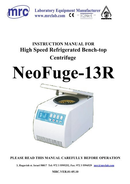
<strong>MRC</strong> leads you to healthier lifeContents1 Safety clauses ·································································································································61.1 Precautions····························································································································61.2 Related judging standard of design························································································72 Introduction of Neofuge 13R <strong>High</strong> <strong>Speed</strong> <strong>Refrigerated</strong> <strong>Bench</strong>-<strong>top</strong> <strong>Centrifuge</strong>·····························72.1 Appearance of Neofuge 13R <strong>High</strong> <strong>Speed</strong> <strong>Refrigerated</strong> <strong>Bench</strong>-<strong>top</strong> <strong>Centrifuge</strong>····················72.2 General··································································································································82.3 Device structure ····················································································································82.4 Safety protection device ········································································································92.5 Technical characteristic·······································································································102.6 Installation requirements ·····································································································102.7 Configuration ······················································································································103 Available optional accessories······································································································114 Preparations before using··············································································································124.1 Transportation and installation ····························································································124.2 Reasonable placement sites ·································································································124.3 Fixed placement of equipment·····························································································134.4 Proper connection of electric supply····················································································135 Operating instructions···················································································································135.1 Control panel and show interface ························································································135.2 Starting of equipment··········································································································145.3 Starting of lid ······················································································································145.4 Shutdown ····························································································································155.5 Installation of rotors ············································································································155.6 Calculation of rotor load······································································································165.7 Samples filling into the centrifugal container ······································································165.8 Safe use of rotors··············································································································165.9 parameter setting··············································································································176 Precautions of maintenance ··········································································································206.1 Clean and Purify··················································································································206.2 Maintenance in the charge of <strong>MRC</strong> ·····················································································214
<strong>MRC</strong> leads you to healthier life6.3 Warranty (contract maintenance) qualification····································································217 Trouble shooting···························································································································227.1 To open Lid in case of emergency·······················································································227.2 Warning message of trouble································································································227.3 Safety protection ·················································································································268 Technical data ······························································································································279 Appendix: Neofuge 13R adapter list................................................................285
<strong>MRC</strong> leads you to healthier life1 Safety clausesNeofuge 13R <strong>High</strong> <strong>Speed</strong> <strong>Refrigerated</strong> <strong>Bench</strong>-<strong>top</strong> <strong>Centrifuge</strong> is designed according to the presenttechnical standards: Machinery Industrial Standards of the People’s Republic of China JB/T 5519-91<strong>High</strong>-speed Refrigeration <strong>Centrifuge</strong> , safety standards: GB/9706.1-1995 Medical Electric Equipment ,Part 1:Universal safety requirements, GB4793.1-1995 Measurement , controlling the laboratory to use thesecurity request for the electric equipment First part : Current requirements, GB4793.7-2001Measurement , controlling the laboratory to use the security of the electric equipment Use the specialrequest for the centrifuge in the laboratory ,GB191-2000 Graphic presentation sign of warehousing andtransportation of the packaging, GB/T14710-1993 The electric equipment environment of medical userequires and test method, GB9969.1-1998 Industrial products operation instructions General provisions.So it must be used according to design requirements. When using Neofuge 13R <strong>High</strong> <strong>Speed</strong> <strong>Refrigerated</strong><strong>Bench</strong>-<strong>top</strong> <strong>Centrifuge</strong> according to the following improper or inappropriate methods, equipment may bedestroyed or men be injured:• To use not accordance with the design requirements;• The operator and maintainer have not been trained;• The user has made improper modification to the design without authorization;• Not notice or understand regulations for safety use.Persons who use or maintain Neofuge 13R <strong>High</strong> <strong>Speed</strong> <strong>Refrigerated</strong> <strong>Bench</strong>-<strong>top</strong><strong>Centrifuge</strong> should read and understand related usage and safety regulations in thisOperating and Technical Instructions.The following regulations should be obeyed to avoid accidents:Operating and Technical Instructions should be put beside “Neofuge 13R <strong>High</strong> <strong>Speed</strong><strong>Refrigerated</strong> <strong>Bench</strong>-<strong>top</strong> <strong>Centrifuge</strong>” for the reference of operators.Neofuge 13R <strong>High</strong> <strong>Speed</strong> <strong>Refrigerated</strong> <strong>Bench</strong>-<strong>top</strong> <strong>Centrifuge</strong> is designed to separate biologic cells,organism and bacteria. The density of the sample won’t exceed 1.2g/cm 3 at the maximum speed.In operation (when the sample is being separated or rotors are running), operators and dangeroussubstances should be absent within 30 cm of the centrifuge. The ventilation hole of the centrifuge can notbe clogged by substances.If the following safety precautions are not obeyed when using Neofuge 13R <strong>High</strong> <strong>Speed</strong> <strong>Refrigerated</strong><strong>Bench</strong>-<strong>top</strong> <strong>Centrifuge</strong>, operators or other persons may be hurt or the centrifuge and samples to be separatedmay be damaged:• The centrifuge is not corrosion proof or implosion proof, so it must be used in the environment free ofcorrosion or implosion;• The following materials should be forbidden:Flammable and explosive substances;Strong chemical materials;Tonic or radioactive substances, or pathogenic microorganism• Corrosive substances may do damage to materials inside the centrifuge and the rotors, so they shouldbe put inside the sealed containers while separating.1.1 Precautions• Before running (when separating samples), appropriate rotors must be fixed firmly;• In operation (when the rotor is running) or the centrifuge has s<strong>top</strong>ped (the rotor is still running),opening the lid by hand is strongly forbidden;• Accessories must be provided by <strong>MRC</strong>. Some common parts, such as glass and plasticcontainers for separating, should also be approved to be qualified products and in be accordance withthe requirements of the highest speed and maximum centrifugal force of related rotors;• Do not use the centrifuge or separate samples is forbidden when the lid is open;• Don’t turn on the power switch of the centrifuge equipment when disassembling the front panel of thecentrifuge;6
<strong>MRC</strong> leads you to healthier life• Changing mechanical parts and electronic devices should be carried out by related persons appointedby <strong>MRC</strong>;• When using the centrifuge, the user must use proper rotors according to load. Overload is forbidden;• The rotor should be checked regularly. If the rotor is eroded or damaged, it should not be used anymore;• Maintenance should be carried out according to “Clean and purify” periodically.1.2 Relevant design and inspection standards:• National standards: Machinery Industrial Standards of the People’s Republic of China JB/T 5519-91<strong>High</strong> <strong>Speed</strong> Refrigeration <strong>Centrifuge</strong>;• Safety standards: GB/9706.1 Medical Electric Equipment, Part 1:Universal safety requirements;• GB4793.1-1995 Measurement, controlling the laboratory to use the security request for the electricequipment First part: Current requirements;• GB4793.7-2001 Measurement, controlling the laboratory to use the security of the electric equipmentUse the special request for the centrifuge in the laboratory;• GB191-2000 Graphic presentation sign of warehousing and transportation of the packaging;• GB/T14710-1993 The electric equipment environment of medical use requires and test method;• GB9969.1-1998 Industrial products operation instructions General provisions;• Meet enterprise standards: Q/TEUC40-2004 Neofuge 13R <strong>High</strong> <strong>Speed</strong> <strong>Refrigerated</strong> <strong>Bench</strong>-<strong>top</strong><strong>Centrifuge</strong>.2 Introduction of Neofuge 13R <strong>High</strong> <strong>Speed</strong> <strong>Refrigerated</strong> <strong>Bench</strong>-<strong>top</strong> <strong>Centrifuge</strong>2.1 Appearance of Neofuge 13R <strong>High</strong> <strong>Speed</strong> <strong>Refrigerated</strong> <strong>Bench</strong>-<strong>top</strong> <strong>Centrifuge</strong>1 23457Figure 1: Back and side view of Neofuge 13R <strong>High</strong> <strong>Speed</strong> <strong>Refrigerated</strong> <strong>Bench</strong>-<strong>top</strong> <strong>Centrifuge</strong>67
<strong>MRC</strong> leads you to healthier life11109Figure 2: Front and bottom view of Neofuge 13R <strong>High</strong> <strong>Speed</strong> <strong>Refrigerated</strong> <strong>Bench</strong>-<strong>top</strong> <strong>Centrifuge</strong>Description of picture one and picture two:1. Lid2. Observation hole at the <strong>top</strong>3. Cover casing in the back4. Ventilation hole in the back5. Foot6. Power jack/switch7. Top panel8. Guy Rope Fastener (for emergency opening)9. heat dissipation hole in the front10. Cover casing in the front11. Control panel and display window2.2 GeneralNeofuge 13R <strong>High</strong> <strong>Speed</strong> <strong>Refrigerated</strong> <strong>Bench</strong>-<strong>top</strong> <strong>Centrifuge</strong> with multi-functional protectionintroduces advanced technology such as speed adjustment via frequency control, microcomputer control,touch button, digital setup, digital LCD. Two kinds of rotors are available (For details, see “Table 1: Typeof rotor and technical parameters”). This centrifuge is used to separate biologic cells, organism andbacteria.2.3 Device structureThis device is composed of many components, such as lid system, chamber system, drive system,rotor system, refrigeration system, base system, electric power system, control system, display system andwarning system.2.3.1 Lid system is composed of the lid, lid hinge, springs, lid lock, lid warning, and opening hole and soon. The lid hinge is at the back of the machine frame and the lid lock is in front of it. Only when are thelid locks on the left and right are locked may the centrifuge run; otherwise the warning system will run(the lights is on and the buzzer sounds) and the device can’t run.88
<strong>MRC</strong> leads you to healthier lifeTo open the lids, you only need to press “ ” (opening key) on the control panel. When the lid riseto certain height, the lid hinge and springs can support the lid.If power cut occurs or the opening key is useless, the sample can be taken out by the following steps:pull the Guy Rope Fastener, then the lid can be opened by hand.When rotors are running and power supply is on, to open lid by hand is forbidden!2.3.2 The chamber system is composed of the internal stainless steel chamber (with refrigerationcopper tube around the exterior wall), rubber seal rings, and rubber shaft sleeves and so on. The chambermay provide a working condition of steady temperature.2.3.3 This device adopts frequency conversion electric machinery to drive the rotor with load sample.The drive system applies pintle to connect and screw to fasten so that the rotor can cooperate withrotor axis and operation runs in order.2.3.4 Rotor system is composed of angle rotor (For details, see Table 1: Type of rotor and technicalparameter), and centrifugal tube etc. The rotor rotates at a certain speed to create a relative centrifugalforce field to separate the samples.As the centrifugal force is several thousand times more than g (acceleration of earth gravity), it isimportant to use and maintain the rotor safely and carefully!2.3.5 The refrigerating system is composed of the compressor, refrigerant agent, evaporator, radiator,fan, digital temperature sensor and so on, which is used to create low-temperature operating environmentfor the centrifugal chamber. The temperature is automatically controlled. When it exceeds the setting value,the compressor works; on the other hand, it s<strong>top</strong>s.The refrigerant agent is R134a, which is not allowed to be changed to another brand! The deviceshould work in an environment with ambient temperature from 5℃ to 35℃, ambient humidity ≤80%.Indoor ventilation must be good, and the constant temperature room with air-conditioners is optimal. Thecompressor is installed in the back of machine frame. The evaporator is mounted around the chamber. Inorder to control temperature, the compressor should be started and s<strong>top</strong>ped consistently. Heat dissipater isinstalled in front of the machine, where air flow and circulation shall be ensured. Dust should be wipedfrom the radiator with a brush or compressed air once every three months to dissipate heat. The digitaltemperature sensor installed at the bottom of the chamber is used to monitor the temperature in thechamber continuously.The temperature in the chamber is different from that of the sample. It takes some time to be same.The temperature set and displayed on the keyboard panel is the temperature in the chamber.2.3.6 The base system is composed of the machine frame, protection steel ring, motherboard, rearcover board and rubber supporting legs and so on.2.3.7 The power supply system includes power supply jack, power switch, which is used to supplyelectricity.2.3.8 The control system includes setting of the rotary speed, running time, temperature, control ofdisplay system and warning system of the complete machine and so on. To ensure proper running of themachine and the safety of the operator, please do not open the cover in front of the device casuallybecause main control circuit board and other electric components are installed on the cover in front of thedevice.2.3.9 The display system is composed of the display board and PVC keyboard panel (control panel). Itis the interactive media. It can show every setting parameter synchronously, and can track the actualchange. In addition, it can display various kinds of troubles and warnings.2.3.10 The warning system consists of over speed, electrical machinery overheat, lid warning etc.When the electrical machine gets over speed, over heat, the system will give an alarm. At this moment, thered warning light on the control panel glimmers, the buzzer sounds the alarm. The machine is unable tostart (starting forbidden). The machine s<strong>top</strong>s automatically, until the trouble is treated. Then the machinecan be restarted. Note: you may press “[ ]” on the control panel to cancel the warning tone soundedby eh buzzer.2.4 Safety protection deviceNeofuge 13R <strong>High</strong> <strong>Speed</strong> <strong>Refrigerated</strong> <strong>Bench</strong>-<strong>top</strong> <strong>Centrifuge</strong> has a series of safety protectiondevices:• The mounting rack is made of steel plate and protection steel ring is made of steel casting. The9
<strong>MRC</strong> leads you to healthier lifeinternal bladder of the inner chamber is stainless. The front frame is made of ABS;The structure of the lid is explosionproof. There is a viewport in the center of the <strong>top</strong>, the frontlocking device.Only when is the centrifuge on and does the rotor s<strong>top</strong>, it is allowed to press “ ” to open the lid.Only when is the centrifuge lid locked, you may start the centrifuge to work!• Overspeed s<strong>top</strong>The warning alarm is given when the rotary speed exceeds the setting speed of 200 r/min. The rotors<strong>top</strong>s automatically if the speed exceeds the maximum rated speed of 250r/min. Wait until the rotors<strong>top</strong>s completely, then open the lid. Restart when the trouble is solved;• Opening forbidden in operation“ ”is pressed by accident in operation, the device won’t respond, however, the warning alarm is given;• Opening in case of emergencyIf the electricity is off or there is something wrong with the rotor abruptly, you may open the lid by handwhen it is useless to open it by pressing (see “Trouble shooting”).Don’t play with safety protection device at will!2.5 Technical specifications2.5.1 Technical dataRated/maximum speed13,000/13,800rpm (fully loaded)Maximum capacity24×2.0gMaximum centrifugal acceleration17,458×g(maximum rated speed)Rated Power390VADrive systemFrequency conversion electric machineryNoise≤57dB(A)2.5.2 Technical parameters<strong>Speed</strong> control range300~13,800r/min<strong>Speed</strong> control precision ± 1%Temperature control accuracy in the chamber ±2℃Temperature Control Range-10℃~40℃Time setting ranges1min~9h and 59mins2.6 Settling the centrifuge2.6.1 This device should be put on the swing-out table-board of the enough rigidity, and be free fromvibration and direct irradiation of the heat source and sunlight.2.6.2 There should be space of 10cm~15cm around the device for the heat of emission of thecondensator.2.6.3 After mounting, to adjust level and make the six shores support at the table-board.2.6.4 Range of application for operational power supply: AC230V,~50 Hz.Earthing for the device should be made, and the ground line of the device should beconnected to that of the electric network!Man-made power cut is forbidden during the rotor’s operation period. Otherwise itwill cause damage to control circuit.2.7 ConfigurationThe following accessories are prepared with the device:(For details, see “Packing list”).10
<strong>MRC</strong> leads you to healthier lifeFigure 5: Rotor number~#1303Figure 6: Rotor number~#13044 Preparations before using4.1 Transportation and installationNeofuge 13R <strong>High</strong> <strong>Speed</strong> <strong>Refrigerated</strong> <strong>Bench</strong>-<strong>top</strong> <strong>Centrifuge</strong> is transported in special-purpose cartonwith protection materials for buffering inside. After opening, the protection materials for buffering shouldbe taken out.• The net weight of the device is about 40Kg, so it is required to lift thedevice on both sides (the left and right) to keep its balance. The coverof the electric apparatus in the front should not be pressed!• Be straight and no vibration when conveying!• Please use special packing cases in long-distance transporting. Bestraight! Handle with care!4.2 Proper place for the centrifugeNeofuge 13R <strong>High</strong> <strong>Speed</strong> <strong>Refrigerated</strong> <strong>Bench</strong>-<strong>top</strong> <strong>Centrifuge</strong> is for indoor use, and the place shouldmeet the following:• A safety clearance of 30cm must be maintained around the centrifuge. When running, there should beno maleficent substance or related person;• The adapter or table should be solid to avoid vibration; if mobile racks or trollies are used, theyshould be with locking devices to ensure the safe operation of the centrifuge;• If the centrifuge is placed beside the wall or in the corner, there should be space of 10cm between theback and the wall and 15cm between the left side and right side and the wall to ensure goodventilation and heat emission.• The centrifuge should be put far away from windows to avoid direct irradiation of the heat source andthe sunlight.• The four supporting legs of the centrifuge should stand evenly on the table-board, which is swing-out.• The centrifuge should be put in the clean room with the constant ambient temperature between 5℃and 35℃ and ambient humidity less than 80%.4.3 Fixed placement of equipmentAfter the centrifuge has been placed, don’t move it frequently. After being moved, be sure the12
<strong>MRC</strong> leads you to healthier lifeDescription of figure 9:1. Electrical machine2. Rotors3. Fastening screws of rotor;4. Electrical machine axis5. Cylindrical pin5.6 The calculation of rotor loadCalculation of maximum load capacityAt the high speed, there is enormous centrifugal force; each rotor is designed to hold enoughmechanical strength at the maximum rated rotary speed-that is “safety factor”; However, the “safetyfactor” determines the rotor load not to exceed it maximum rated load.When separating samples, the total weight is not allowed to exceed the maximum rated load of therotor. Otherwise, you should reduce the weight of samples or calculate permissible running speed (N PERM )to ensure the rotor load not to exceed its maximum rated load.Calculation method of permissible running speed (N PERM )is as follows:N PERM =Nmax ×(maximum permissible load/actual load) 0.5Nmax:Maximum rated rotary speed;Maximum permissible load;Actual load.No overloading! The rotor may explode, thus pieces produced may do damage tothe centrifuge!5.7 Samples filling into the centrifugal containersTake care of the operation life of centrifugal containers used, especially the ones rununder maximum permissible load (velocity, temperature). Please change it for a new oneif the centrifugal container (plastic, glass container) is damaged.Please carefully ensure the centrifugal container (centrifugal tube ect.) to be inaccordance with permissible maximum rated acceleration (centrifugal force); pleaseslow down for use if possible.When the centrifuge runs it is better to keep balance. It should not be interfered due tovibration in separated area for samples. So it is necessary to fill the centrifugal containerwith samples evenly. All samples should be placed in appropriate containers.Take care of the operation life of centrifugal containers used, especially the ones rununder maximum permissible load (velocity, temperature). Please change it for a new oneif the centrifugal container (plastic, glass container) is damaged.5.8 Safety use of rotor5.8.1 Before the rotor runs, you should load samples and place tubes correctly and symmetrically.5.8.2 When changing rotors, please unscrew bolts in the counterclockwise direction to loosen therotor.5.8.3 Starting is forbidden until the fastening screw of the rotor is in the rotary axis!5.8.4 When repeated running is needed for the centrifuge, you should check the fastening screw afterthe rotor has run several times. If it is loosed, it needs to be fastened before starting.5.8.5 It is allowed to load samples into the centrifugal tubes symmetrically at different time.Asymmetrical loading is strictly forbidden.16
<strong>MRC</strong> leads you to healthier life5.9 Parameters settingAttention:• You should install the rotor in the rotary shaft before setting parameters.• Touching buttons are applied. You merely need to tightly touch related places when settingparameters.• You may set up the parameters again when mistakes occur in the operation.5.9.1 Setting of rotary speed:Rotary speed range of Neofuge 13R <strong>High</strong> <strong>Speed</strong> <strong>Refrigerated</strong> <strong>Bench</strong>-<strong>top</strong> <strong>Centrifuge</strong>:The minimum rotary speed: 250r/min, the maximum rotary speed: 13, 800 r/min.Set rotary speed of rotors according to the following steps:To press [▲] and [▼] on “<strong>Speed</strong>” icon of control panel (as shown in figure 7) one time to requirethe preset numerical value and the numerical value won’t be changed during the periods of s<strong>top</strong>pingand running. Continue to press it for more than one second to add or decrease preset rotary speed.At the same time, the lowest line on main interface shows [↑↓] on the left side and preset rotaryspeed on the right side. The date will be stored into the system automatically and theinterface returns to its original status when setting is finished two seconds.5.9.2 Calculation on centrifugal forceGenerally speaking, the relative centrifugal force is several thousand times more than the G-force (g).It is the unit to measure the efficiency of various instruments to separate or deposit things. The calculationof the centrifugal force is related to the centrifugal rational speed and centrifugal radius. The method is asfollows:RCF =11.18 ×(n/1000) 2 × rr:Centrifugal radius, unit: cm;n:Centrifugal speed, unit: rpm (Rpm)Attention:The numerical value of the maximum centrifugal force is related to the maximum radius“rcf” value showed on the interface is calculated according to the radius of rotors.5.9.3 Setting of running time:Setting range of running time of rotors:1m~9h and 59m.To press [▲] and [▼] on “Time” icon one time to require the preset numerical value and thenumerical value won’t be changed during the periods of s<strong>top</strong>ping and running. Continue to press it formore than one second to add or decrease preset running time. At the same time, the lowest line onmain interface shows [↑↓] on the left side and preset time on the right side. The date will be storedinto the system automatically and the interface returns to its original status when setting is finishedtwo seconds.The 3 rd area of figure 8 shows preset time.5.9.4 Setting of temperature:Setting range of control temperature in the chamber: (The minimum temperature of different rotorsis different at different rotary speed).To press [▲] and [▼] on “Temp” icon one time to require the preset numerical value and thenumerical value won’t be changed during the periods of s<strong>top</strong>ping and running. Continue to press it formore than one second to add or decrease preset temperature. At the same time, the lowest line onmain interface shows [↑↓] on the left side and preset temperature on the right side. The datewill be stored into the system automatically and the interface returns to its original statuswhen setting is finished two seconds.Notes: the data of the users can be revised at any time. For example: the time when the lid is opened,closed or is running.5.9.5 Running of device‣ The device can’t start until the users’ data have been set, the rotor has been installed, samples to beseparated placed correctly and the lid closed.17
<strong>MRC</strong> leads you to healthier lifeAttention: A lid lock icon on the main interface may tell you “Whether the lid of the device is closedcorrectly”.‣ Temperature controlAfter temperature setting completed, when the lid is completely closed, the rotor is not started and thesetting temperature is lower 5℃ than that of the chamber, the compressor may start at once <strong>top</strong>re-refrigerate. The 1 st area of main interface shows “· ” on the <strong>top</strong> right corner. The compressors<strong>top</strong>s at the time the temperature in the chamber meets the setting temperature+ 5℃to ensue thetemperature of the sample and that in the chamber are the same at the setting speed within 30 minutesafter the separating starts. If the rotor is in operation, refrigeration system will start up until it reachespreset temperature.‣ Centrifugal work starts1. To press the start key [►] on the control panel. The rotor begins to rotate when the lowest line onmain interface shows [ ] on the left side and [Running] on the right side.2. At the same time the running time is counting down from “preset time”. When it displays zero, that is“00:00:00”, the centrifuge s<strong>top</strong>s and the work is finished;3. Temperature display window of chamber shows “actual temperature”, working with refrigerationsystem. The temperature in the chamber is falling rapidly from “+00℃”. When the temperaturetouches the setting temperature, the compressor s<strong>top</strong>s;4. In operation, the rotary speed and the centrifugal force (see Figure 8) rise separately from “00000”and “00000” until they reach the setting “Rotary speed” and “Centrifugal force”, and the centrifugalforce of them is converted automatically according to the rotor detected;5 There should be warning prompts if the rotary speed the rotor exceed the permissible maximumvalue or setting value; and when there are temperature protection operation of the electric machinery,overheat operation of the compressor and something wrong with the (EEROM, RAM) and so on, themachine shall alarm, the buzzer shall sound and the warning red lights flash.6. Opening of the lid is forbidden while the rotor is running.Attention:For more details about concrete warning prompts, see “Trouble shooting”.‣ Short-time centrifugationWhen the centrifuge is stand by, continue to press key for 2 seconds. The centrifuge willaccelerate to the highest speed allowed by the rotor. At the same time, display area begins to showtime. The low line of the display screen shows [ ] on the left side and [Click Mode] on theright sideLose key , the centrifuge fastly deaccelerates to zero. Time display area keepsshort-time of running. Repeat the above steps to finish short-time centrifugation. At thesame time, continue to add up the time.5.9.6 Modification of parameter during operationThe parameters of rotary speed, control temperature and running time and so on can be modified duringoperation.After the parameter has been modified and the main interface menu appears, the newly settingparameters will come into effect.5.9.7 Termination of the centrifuge operationThere are two ways to terminate the centrifuge operation:1. In normal operation, the running time has been set. So when the running time is out, the centrifugewill s<strong>top</strong> automatically.When the rotary speed of the rotor falls to zero, that is “RPM:00000” and “RCF:00000”, you maypress the opening key “ ” on the control panel and lift the lid slightly to open the lid. The state ofthe lid lock displays the tapered end is open, then you can take out the samples separated in thecentrifuge.2. In normal operation, you may press “■” on the control panel any time to terminate the centrifuge onhalf way, and the centrifuge s<strong>top</strong>s immediately. The countdown s<strong>top</strong>s at the same time. You can press“ ” to open the lid only the “RPM” and “RCF” (centrifugal force) centrifugal force) displayed fallto zero. The state of the lid lock displays the tapered end is open at the same time, and then you cantake out the samples separated in the centrifuge.18
leads you to healthier life5.9.8 Precise control of temperature in the chamberIf the lid is closed and the instructions to start has not been issued, the centrifuge will change thecontrol temperature automatically, 5℃ above the setting temperature. When the temperature in thechamber is at least +6℃ above the setting temperature, the compressor starts to refrigerate. And thecompressor s<strong>top</strong>s when the temperature in the chamber is +5℃ above the setting temperature. Thus,separated samples are protected not to freeze when the rotor doesn’t work.In operation, the temperature will keep 2℃ above or below the setting temperature after the refrigerationsystem has worked some time.5.9.9 Disassembling of rotorsAttention: When disassembling rotors, you should catch them and lift by bothhands. Vibration is forbidden.Steps to disassemble rotors are as follows:1. To s<strong>top</strong> the centrifuge;2. To open the lid;3. To unscrew the fastening screw in the counterclockwise direction with special tools (torque spanneror inner hexagon spanner of 5mm) for disassembling.4. To catch the rotor by both hands and vertically lift it along the direction of the fastening screw.Vibration is forbidden;5. You may take the sample separated, container and rotor from the fastening bolt (lock sleeve of therotor) if the sample separated is polluted or to prevent it to be polluted!6. Then you may take the sample from the rotor in appropriate places where there are preventivemeasures, for example:to put the sample separated, container and rotor in the safe chest for biologicaloperation and open the rotor to take the sample out after being purified.5.9.10 Alarm clearance• Description of trouble messageThe low line of the display screen shows all trouble messages, [ ] on the left side and relativetrouble messages on the right side. At the same time, the buzzer shall sound and the warning redlights flash.Alarming sound will not vanish automatically, but it can be eliminated by the operator. Press key [ ] tocancel the warning of the buzzer. Red lights alarming will not cancel automatically until finally the troubleis solved.Table 2:Table of trouble message promptOver max speedCurrent rotary speed of rotor exceed max rated rational speedover set speedCurrent rotary speed of rotor exceed the setting speedcompressor overheatCurrent temperature of the compressor is too high, andprotective operations take placelid opened when runLid is opened when the device runs (centrifugal operation)lid open failedLid is not opened correctlyspeed sensor errorSomething wrong with speed sensortemp control failedSomething wrong with temperature controlI2c BUS error12C warningregister errorSelf-check register warningcpu ram errorself-check internal ram warningeeprom errorSomething wrong with read-write of EEPROMIllegal power offSomething wrong cause Illegal power off19
leads you to healthier life5.9.11 Operation recordsPlease keep records of each operation (one for each device) to ensue the normal operation of theequipment and prolong the service life and for the accumulation of operation data of equipment todiagnose the trouble and the cause of the accident. The recommended table of operation data is as follows:Table 3 Table of operation recordsDate oftestName ofsampleWeight ofmonotube(including sample)RotorNo.RotaryspeedTimeTemperatureWorkingconditionOperator6 Maintenance6.1 Clean and PurifyUsers have the responsibility to clean and purify the centrifuge when dangeroussubstance spills over into the machine. Users shall clean and purify it according to themethod recommended by the manufactures to ensure that the machine won’t be damagedwhen using cleaning and purifying methods not recommended by the manufactures.Inappropriate detergents and incorrect methods may do harm to the centrifuge orspare parts inside;Cleaning and sterilization should be carried out according to operating proceduresdescribed in the operating and technical instructions.6.1.1 Implementation of cleaning and purifyingTurn off the power switch and draw out the power wire before cleaning!The centrifuge shell, rotor chamber, rotor and centrifugal containers used and so on should be cleanedand maintained regularly (or determined by the service condition); thus contamination on them can becleared away to avoid damage to the spare parts used and environments pollution.If you are not clear which kind of should be selected for use while washing solvents while cleaningthe centrifuge, please contact .Organic solvents are forbidden, as they can’t decompound grease in the bearings ofthe motor;Liquid, especially organic solvents should be in contact with the supporting shaftand ball bearings when being cleaned;If there is frost or thin ice layer, they should be cleaned away when they changeinto water.6.1.2 Implementation of high-pressure sterilizationRotors used by this centrifuge can have high-pressure sterilization. Temperature: 121℃Absolute pressure: 250kPa, keep for at least 10 mins. Please refer to instructionsoffered by other manufactures on other separating containers.Check whether it is permissible to sterilize rotors and containers withhigh-pressure;The temperature and time for high-pressure sterilization should be strictlycontrolled according to different rotors and containers for separating;Don’t use the rotor and container for separating if they corroded or damaged.20
<strong>MRC</strong> leads you to healthier life• Installation, debugging, position changing, accessories adding, maintenance and so on are carried by <strong>MRC</strong>or professional persons;• Normal maintenance is carried out regularly according to methods determined in the operating andtechnical instructions. <strong>MRC</strong>will repair damaged devices not free of charge if the damage is caused by users becausethey operate them incorrectly. <strong>MRC</strong>will treat any problem of the device quality (except damage caused due to incorrect operation)free of charge within one years from the day when the device sells; you should pay for the repair if theperiod of warranty is out.7 Trouble shooting7.1 To open lid in case of emergencyIn normal use, the function of automatic opening is forbidden when the electricity is off or theoperation to open the lid is disabled by accident. However, things in the chamber must be taken out. In thiscase, you may open the lid of the centrifuge by hand to take samples out. Attention: this is for emergencyonly!When the electricity is off and there is no brake, the rotor will run a long time.Please wait!Steps to open the lid in case of emergency are as follows:7.1.1 To confirm all the rotors are not running (to observe from the eye hole at the <strong>top</strong> of the lid);7.1.2 To turn off electricity;7.1.3 As the picture 2 show: there is a Guy Rope Fastener in the Front and bottom of <strong>Centrifuge</strong>. Dragthe rope, and then pull the rope, the Latch Assembly will be opened. Open the door closure, you can takeout the sample separated in the centrifuge.7.1.4 When the power supply is on, turn on the electricity;The control parts of the lid lock will return to the normal condition automatically whenthe self-check is completed. After that, you may press the lid slightly to make it locked automatically.7.2 Warning message of troubleThe warning messages and treatment are listed in the following table. You may deal with themaccording to prompts; if you can’t deal with them or the warning messages are not listed, please contactmaintainers of <strong>MRC</strong> at once.22
<strong>MRC</strong> leads you to healthier lifeTroubleNo display or nodisplay abruptlyThe device s<strong>top</strong>sabruptlyTable of warning message of trouble (1)Cause of trouble and treatmentNo electricity, connection of the power supply is not good or abrupt power cut• To check whether the supply socket and the wire is in good condition, andthe socket is live;• Connection of the power switch not in good condition;• Please contact maintainers of <strong>MRC</strong> if you can’t solve it.Cause of trouble:1. Exceeding the maximum rated speed of the rotor:If the rotary speed exceeds the rated speed of 250r/min, there will be awarning alarm. At the moment, you should s<strong>top</strong> the device to reset the rotaryspeed;2. Exceeding the setting speed of the rotor:3. Electric machinery of frequency conversion overheated or compressoroverheated:At this moment, the electricity is cut off inside the device. The device s<strong>top</strong>s;4. Over-temperature in the chamberCheck whether the setting temperature is above 37℃ and temperaturedisplayed on the control panel. The former should be set below. Thetemperature in the chamber should fall to the room temperature. However,restart according to requirements.5. Please check the electricity if there is no display on the keyboard panel.6. The voltage may be too low. Check the supply voltage.Lid lockedMajor vibrationDigitron indicatorlamp on the controlpanel off whenthe power switch isturned onControl paneldisplay abnormalButton pressed, norun for the electricmachine1. The lid should be locked if the rotor is still running.2. Manually open the door after the power is switched off, and then switch onthe power again to see if it is normal.3. Safety-protection procedure activates when the power fails unexpectedly.Operator can’t open the lid until 5 minutes after the power is switched on..4. Please contact maintainers of <strong>MRC</strong> if you can’t solve the problem.1. Exceeding the critical speed. Minor vibration is permissible.2. Check whether the rotor is locked firmly.3. Check symmetry of the load of rotors. Ensure the device is swing-out.4. Check the mounting of rotors.5. Check the transmission shaft. Turn it by hand. If it can’t run smoothly, theremay be something wrong. Please contact maintainers of <strong>MRC</strong> if you can’tsolve the problem.1. No connection to the power supply. Check the distribution power.2.Two fuses of 6.3A on the PCB board are burnt out. Please ask for professionalsto change them.3.Please contact maintainers of <strong>MRC</strong> if you can’t solve the problem.Maybe it is interfered by the electric network. Turn off and wait for one minute.Turn on the device, and then everything will be all right.1. Check the electricity of the frequency conversion board.2. Electric control circuit failed. Change the electric control panel.23
<strong>MRC</strong> leads you to healthier lifeTable of warning message of trouble (1) (continued)No cooling or can notreach to presettemperature1. The room temperature is too high. Make it below 30℃.2. The fuse is burnt out. Change it.3. There are errors in setting of temperature. Reset parameters.4. The system isn’t sealed. Add refrigerant fluid after checking.5. The cooling fan doesn’t work. Check the electric wire or change it for a newone.6. The temperature sensor is bad. Change it for another one.7. The compressor is bad. Change it for another one.8. There is something wrong with the control panel. Change it for another one.9. Dust on the condensor is too thick. Clear it away.Burnt smoke smellfrom the machineOther troubles1. Cut off electricity.2. Whether the electric machine is burnt out.3. Whether the electric units are burnt out.4. Turn the transmission shaft by hand. If the shaft doesn’t rotate smoothly,please ask professionals from the manufacturer for help.Solved by professionals from the manufacturer.24
<strong>MRC</strong> leads you to healthier lifeTrouble messages“over max speed”“over set speed”“compressor overheat”“lid opened when run”“lid open failed ”“speed sensor error”“temp control failed”“I2c BUS error ”“register error”Table of warning message of trouble (2)Cause of trouble and treatmentCause of trouble:Current rotary speed exceeds the maximum rated speedmore than 250rpm;• Maybe it is overshoot. Return to the normal state automaticallyseveral seconds later;• Please contact maintainers of <strong>MRC</strong> if you can’t solve it.Cause of trouble:Current rotary speed exceeds the setting speed more than200rpm;• The acceleration may be overshoot. It will return to normal stateseveral seconds later;Cause of trouble:Overheated protection of compressor or overheatprotection of electric machine operates;• Whether the fan s<strong>top</strong>s or not;• The compressor doesn’t work well;• It will cool automatically;Cause of trouble:Lid of the device is open or not closed completely; rotor isrunning;• The warning alarm will disappear when the rotor s<strong>top</strong>s completely;• Close the lid again;Cause of trouble:opening of the lid failed• Close the device again, then start;• When there is something wrong with the PCB control circuit, pleasecontact maintainers of <strong>MRC</strong> if you can’t solve it• Please open the lid by hand when you need to take sample( please referto 7.1)Cause of trouble:speed sensor ineffective (no signal);• Close the lid again, then start;• When there is something wrong with the PCB control circuit, pleasecontact maintainers of <strong>MRC</strong> if you can’t solve itCause of trouble:temperature control failed• Whether the preset temperature is higher than 37℃;• Whether the temperature in the chamber is higher than 37℃;whetherthe compressor can work orderly;• If the trouble can not be solved, something wrong withtemperature sensor or cooling system, please contactmaintainers of <strong>MRC</strong>.Cause of trouble:I2C bus drive signal read-write error;• Shut down, then start;• When there is something wrong with the PCB control circuit, pleasecontact maintainers of <strong>MRC</strong> if you can’t solve itCause of trouble:RAM of micro-processor (CPU) read-write error;• Shut down, then start;• When there is something wrong with the PCB control circuit, pleasecontact maintainers of <strong>MRC</strong> if you can’t solve it25
<strong>MRC</strong> leads you to healthier lifeTable of warning message of trouble (2) (continued)“CPU RAM ERROR”“EEPROM ERROR”“Illegal power off”Cause of trouble:RAM of micro-processor (CPU1) read-write error;• Shut down, then start;• When there is something wrong with the PCB control circuit, pleasecontact maintainers of <strong>MRC</strong> if you can’t solve itCause of trouble:EEROM read-write error;• Shut down, then start;• When there is something wrong with the PCB control circuit, pleasecontact maintainers of <strong>MRC</strong> if you can’t solve itWhen s<strong>top</strong>ping moving round in rotor travel process, since the malfunctionleads to a rotor (For instance: Power cut), must close a mains switch, shouldopen up the mains switch, when check up once again after being over, givesan alarm in that kind appearing on host interface, see that after being theinformation giving an alarm's turn, need to wait for 5 ~ 10 minutes, startsthe rotor travel once again, any button will be to become invalid in theprocess waiting!7.3 Safety protection7.3.1 Protection function of automatic s<strong>top</strong>pingNote:All protection functions will come into effect once the electricity is on.• Safety protection for “Overspeed”:If the rotary speed of the rotor is 250r/min above the rated speed,the protection function of automatic s<strong>top</strong>ping for “Over maxspeed” will come into effect. The promptmessage “OVER ROTOR MAX SPEED” appears and the buzzer alarms at the same time. If therotary speed of the rotor is 250r/min above the rated speed, the device will s<strong>top</strong> automatically.• Safety protection for “Overheat”:If the temperature in the chamber exceeds 37℃, the protectionfunction of automatic s<strong>top</strong>ping for “Overheat” will come into effect. The prompt message “TEMPCONTROL Failed” appears and the buzzer alarms at the same time.• When the running time is out, the device will s<strong>top</strong>s automatically, and the running time becomes “00:00:00”.• Processing program in case of abnormity• If there is abnormal vibration, noise or peculiar smell, shut down the device, cut off the electricity,take samples out and check. Please contact <strong>MRC</strong> if you can’t solve it.• Notice for technology supportPlease inform the maintainer of <strong>MRC</strong> of the serial No. and version No. in advance for convenientdiagnosis when you need our help.You may find the serial No. on the nameplate at the back of the device. You may find the versionNo. of the software on the display when the machine is opened.26
leads you to healthier life8 Technical dataFunction/ParameterOperating environmentAmbient temperature • +5℃ ~ +35℃Applied voltage • AC230 V~50HzRated power • 390VAType of fuses and parameter • 317, 125 in, 250VAX, 6.3ASet time range • 1min~9h and 59minTechnical indicators• Used at home.• There are no electric dust and volatile gas and corrosive gas to exist in theambient air; There are no vibration and airflow to influence the performancearound• Altitude: ≤2000m• Relative humidity: ≤80%Rated/Maximum rotary speed ofrotor (speed max)• 13,000/13,800 RPMMinimum rotary speed (speedmin)• 300RPM(recommended range:2000---13,000RPM);Maximum centrifugal force(RCFmax)• At the maximum rotary speed (speed max), the maximum centrifugal force(RCFmax) is 17,458×g;Ascending velocity • Max(highest) ascending velocity, less than 1min;Descending velocity • Minimum (lowest) descending velocity, less than 1min;Refrigeration effect• When temperature of the centrifugal chamber is equal to that of the ambienttemperature, 20 ℃ ±5 ℃ , that the temperature in the chamber lasts 30 minutes at-5℃ is not allowed;Complete machine vibration • Complete machine vibration of the centrifuge should not exceed 0.5gSteady precision of rotary speed • ±1%Time error of centrifuge • Time error of centrifuge:±1m per 30m.Noise (At the maximum speed) • Less than 57dB at the maximum speed;External dimensions (Device) • 480mm(L)* 285mm(W)* 320mm(H)Net Weight (with rotor): • 40kgExternal dimensions(Packaging) • 696mm(L)* 500mm(W)*635mm(H)Gross Weight • 45Kg• Machinery Industrial Standards of the People’s Republic of China JB/T5519-91 <strong>High</strong>-speed Refrigeration <strong>Centrifuge</strong>;• Safety standards: Designed according to GB/9706.1 Electric Equipmentfor Medical Use- Part 1:Universal safety requirements;• GB4793.1-1995 Measurement, controlling the laboratory to use the securityrequest for the electric equipment First part: Current requirements;Relevant standard that quotes:• GB4793.7-2001 Measurement, controlling the laboratory to use the security ofthe electric equipment Use the special request for the centrifuge in thelaboratory;• GB191-2000 Graphic presentation sign of warehousing and transportation ofthe packaging;• GB/T14710-1993 The electric equipment environment of medical use requiresand test method;• GB9969.1-1998 Industrial products operation instructions General provisions;• Meets Enterprise standards: Q/TEUC40-2004 Neofuge 13R <strong>High</strong> <strong>Speed</strong><strong>Refrigerated</strong> <strong>Bench</strong>-<strong>top</strong> <strong>Centrifuge</strong>.27
9. Appendix: Neofuge 13R adapter listRotor no.#1301#1303capacity(ml)BottomfigureVessel parameterdimensilength(mm)Number/SetNameons(mm)1.5/2 Ø11 47 24 none0.5 18°conic1×0.5mlØ8 32 24adapter0.2 18°conic1×0.2mlØ6.5 22 24adapteradapterOrder no.Number/SetcolorADP17.02-001 24 yellowADP17.02-002 24 blueRotor no.capacity(ml)BottomfigureVessel parameterdimensilength(mm)Number/Setons(mm)#1302 8×0.2 18°conic Ø6.5 4×8 none#1304 0.2 18°conic Ø6.5 22 24 noneNameadapterOrder no.Number/Setcolor28