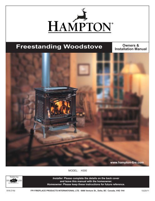
Freestanding Woodstove - Regency Fireplace Products
Freestanding Woodstove - Regency Fireplace Products
Freestanding Woodstove - Regency Fireplace Products

You also want an ePaper? Increase the reach of your titles
YUMPU automatically turns print PDFs into web optimized ePapers that Google loves.
INSTALLATIONPRE-INSTALLATIONASSEMBLYAfter removing the stove from its packing, openthe front door and remove the contents from thefi rebox, leaving the bricks in place.Draft ControlLever HandleRotating ElbowThis stove can be connected to either a top orrear vent exit by simply reversing the orientationof the elbow.Simply remove the 2 screws, change the positionof the elbow as desired and secure in placewith screws.Side LoadDoor Handle1) To install side door handle, remove sidedoor plug assembly.Side Door Plug AssemblyDoor Latch Bar1) Insert bolt and lock washer through draftcontrol lever hole.2) Place handle through bolt. Tighten to secure.Rear Heat ShieldHex NutsFlat WashersSide DoorPlugHandleWasherBolt1) Loosen the bolts that secure the elbow tothe unit. Ensure elbow does not fall off.2) Bend the tabs on the rear heat shield inwards90 degrees.2) Assemble handle by:a) Placing lock washer over hex head bolt.b) Place hex head bolt into handle.c) Place spacer over hex head boltthreads.d) Screw handle into side door latch.LatchSpacerHandleDraft Control LeverBend tabs inwards 90 degrees.3) Slide the tabs on the rear heat shield inbetween the bolt and washer.LockWasherHex HeadBoltPlease Note: The shield needs to be stretched/fl exed in order to fi t in place.3) Place side door handle latch through sidedoor hole.4) Re-assemble side door plug assembly tosecure.Side DoorPlug AssemblyLatchSlide tabs in betweenwasher and bolt.Rear Heat Shield4) Once rear heat shield is evenly in place,tighten bolts to secure.Hampton H300 Cast <strong>Freestanding</strong> <strong>Woodstove</strong>7
INSTALLATIONRESIDENTIALINSTALLATION1) Please read this entire manual before youinstall and use your new woodstove. Failureto follow instructions may result in propertydamage, bodily injury or even death. Beaware that local Codes and Regulationsmay override some items in this manual.Check with your local inspector.2) Select a position for your Hampton Stove.Consult the minimum clearance chart foryour model and set the stove in place. Forclose clearance installation use listed doublewall connector systems.3) To insure vertical alignment, suspend aplumb bob from the ceiling over the exactcenter of your stove fl ue and mark a spoton the ceiling to indicate the center of thechimney.4) Check that the area above the ceiling isclear for cutting. Re-confi rm the clearancefrom the stove to combustibles to insure thatthey are within the prescribed limits.5) This woodstove must be connected to aUL 103 HT (ULC S629) listed chimney ora code approved masonry chimney with afl ue liner.6) Install chimney according to chimney manufacturersinstructions. The performance ofyour woodstove is governed to a very largepart by the chimney system. Too short achimney can cause diffi cult start-up, dirtyglass, backsmoking when door is open, andeven reduced heat output. Too tall a chimneymay prompt excessive draft which can resultin very short burn times and excessive heatoutput. The use of an inexpensive fl ue pipedamper may be helpful in reducing excessivedraft.CAUTION: The chimney should be the samesize as the 6" (152mm) fl ue outlet on thestove. The chimney must be listed as suitablefor use with solid fuels. For other typesof chimneys check with your local buildingcode offi cials. Do not confuse a chimneywith a type “B” Venting System used for gasappliances as suitable for a wood burningappliance (refer to the Mobile Home installationssection).7) Mark the location of the legs on the fl oor,then move the stove aside and mark theposition of the fl oor protector.8) The fl oor protector must be of non-combustiblematerial and must extend 18" (457mm)in front of the door opening and 6" (152mm)to the sides and rear of the unit. Some areasmay require a larger size fl oor protector.Refer to the Mobile Home Installation sectionfor outside air installation instructionsand see your local inspector.NOTE: In Canada, floor protection must extend18" (450mm) to the front and 8" (200mm)to each side and back of the stove.9) When the fl oor protection is complete, positionthe stove with the fl ue collar centeredunder the installed chimney.10) In seismically active areas, we recommendthat your unit is secured to the fl oor by usingthe bolt down holes inside the legs (the sameones used in Mobile Home installations).11) For residential installations using 6"(152mm) "C" Vent (single wall) the chimneyconnector must be at least 24 gauge steel.Do not use galvanized pipe (refer to theMobile Home installation section).12) Do not connect this unit to a chimneyserving another appliance.13) A chimney connector cannot pass throughan attic or roof space, closet or similarconcealed space, or a fl oor, ceiling, wallor partition of combustible construction.In Canada, if passage through a wall, orpartition of combustible construction isdesired, the installation shall conform toCAN/CSA-B365, Installation Code for Solid-Fuel-Burning Appliances and Equipment.14) Your Hampton <strong>Woodstove</strong> is not to be connectedto any air distribution duct.Emissions from burning wood or gas couldcontain chemicals known to the State ofCalifornia to cause cancer, birth defectsor other reproductive harm.MODULAR INSTALLATION OPTIONSOPTIONS: These can be installed at time of installation or added later:Modular OptionBlower/FanSide Load DoorOutside AirAdaptorSide ShelvesShort legsThings to consider when choosing optionsAdding the blower will increase the area heated by the stove, it can move warm air beyond the room where the stoveis installed (refer to the Optional Blower / Fan Installation section).The side load door allows for putting in larger logs into the fire easier ( refer to Side Load Door section).Helps combustion in small or poorly ventilated houses. Installation instructions come with adaptor.Add to the traditional look of the stove and double as a warming area for your cookstove creations.Helps in reducing the overall height of the unit to accomodate a variety of installations. Using this option prohibits theuse of the ash drawer.8Hampton H300 Cast <strong>Freestanding</strong> <strong>Woodstove</strong>
INSTALLATIONMINIMUM CLEARANCE TOCOMBUSTIBLE MATERIALSPlease read the section below carefully. Measurements "From Unit" are from the top plate of the stove to a side wall or to a corner, and from therear heat shield to a back wall.Clearances may only be reduced by means approved by the regulatory authority.* Minimum clearance withside load door in use is 18"(457mm) to side wall or referto dimension (A) if side loaddoor is not used.NOTE: Be aware that local Codes and Regulations may override some clearances listed in this manual.Check with your local inspector.Residential Installation “C” Vent (Single Wall)Unit (with Heat Shield) From Unit From From Flue Center-LineCornerA B C D E FH300 17" (431 mm) 15" (381 mm) 13" (330 mm) 30" (762 mm) 15" (381 mm) 19" (483 mm)Residential Close Clearance (To be installed with required pipe components)When the stove is installed as a close clearance residential unit, a listed double wall connector is required from the stove collar to the ceilinglevel.Unit (with Heat Shield) From Unit From From Flue Center-LineCornerA B C D E FH300 15" (381 mm) 10" (254 mm) 9" (228 mm) 28" (711 mm) 10" (254 mm) 15" (381 mm)Mobile Home Close Clearance (To be installed with required pipe components)"C" Vent single wall pipe is not approved for Mobile Home installations. (Refer to Mobile Home section).Unit (with Heat Shield) From Unit From From Flue Center-LineCornerA B C D E FH300 15" (381 mm) 10" (254 mm) 9" (228 mm) 28" (711 mm) 10" (254 mm) 15" (381 mm)Hampton H300 Cast <strong>Freestanding</strong> <strong>Woodstove</strong>9
INSTALLATIONMINIMUM ALCOVE CLEARANCE TOCOMBUSTIBLE MATERIALSThis Hampton <strong>Freestanding</strong> model has been alcove approved and must be installedwith a listed double wall connector to the ceiling level.Note: Minimum alcove ceiling height (from finished floor) - 60" (1525 mm)Maximum depth of alcove - 48" (1220 mm)From From Flue Min. Min.HearthUnit (with Heat Shield) Unit Center-line Width to Rear WallG H I J K LH300 15" (381 mm) 13" (330 mm) 28" (711 mm) 13" (330 mm) 57" (1448 mm) 51-1/4"without side load door (1301 mm)ADDITIONAL CLEARANCESFOR BACKWALL EXIT60" (1524 mm)with side load doorMinimum Clearance to CombustiblesFromUnit (with Heat Shield)UnitABH300 9" (228 mm) 15" (381 mm)Min. Mantel Height (from finished floor): 48" 1219 mmMax. Mantel Depth: 12" 305 mmMinimum Clearance to Non-CombustiblesFromUnit (with Heat Shield)UnitABH300 min. 0" (0 mm) 15" (381mm)max. 9" (228 mm)Note: Floor Protection must extend 2" (50mm)to each side of the elbow.Note: If side load door is used, floor protectionmust extend at least 18" (457mm) fromthe side of the unit.10Hampton H300 Cast <strong>Freestanding</strong> <strong>Woodstove</strong>
INSTALLATIONFLOOR PROTECTIONA combustible fl oor must be protected by non-combustible material (like tile, concrete board, or certifi ed to UL-1618 or as defi ned by local codes)extending beneath the heater and a minimum of 6" from each side and minimum 18" from the front face of the stove and minimum 6" (or the rearclearance to combustibles whichever is smaller) from the rear of the stove.When installed with horizontal venting, non-combustible fl oor protection must beneath the fl ue pipe and extend 2" (51mm) beyond each side.A minimum of a 1/2" thick thermal fl oor protector with a 0.75k factor is required when installing the standard or optional short legs. This applies toboth Canada and the US. All other requirements (ie. hearth size) remain the same.IF SIDE LOAD DOOR IS USED:Floor protection must extend 18" (457mm)from the side of the unit to the wall.NOTE: In Canada, floor protection mustextend 18" (450mm) to the frontand 8" (200mm) to each side andback of the stove.Minimum Overall Depth (Y) of Floor ProtectorResidential Residential Mobile Home AlcoveUnit "C" Vent Close Clearance Close ClearanceY Z Y Z Y Z Y ZH300 (US) 44-1/2" 6" (152 mm) 44-1/2" 6" (152 mm) 44-1/2" 6" (152 mm) 44-1/2" 6" (152 mm)(1130 mm) (1130 mm) (1130 mm) (1130 mm)H300 (Canada) 46-1/2" 8" (203 mm) 46-1/2" 8" (203 mm) 46-1/2" 8" (203 mm) 46-1/2" 8" (203 mm)(1181 mm) (1181 mm) (1181 mm) (1181 mm)Minimum Overall Width (X) of Floor Protector for all installations:H30039" (990 mm) - US43" (1092mm) - CanadaHampton H300 Cast <strong>Freestanding</strong> <strong>Woodstove</strong>11
INSTALLATIONHOW TO DETERMINE IFALTERNATEFLOOR PROTECTIONMATERIALS AREACCEPTABLEThe specifi ed fl oor protector should be 3/8"(18mm) thick material with a K - factor of0.84.The proposed alternative is 4" (100mm) brickwith a C-factor of 1.25 over 1/8" (3mm) mineralboard with a K-factor of 0.29.Step (a):Use formula above to convert specifi cationto R-value.R = 1/k x T = 1/0.84 x .75 = 0.893.1) With your location already established, cutand frame the roof hole. It is recommendedthat no ceiling support member be cut forchimney and support box installation. If it isnecessary to cut them, the members mustbe made structurally sound.2) Install radiant shield and support fromabove.3) Stack the insulated pipe onto your fi nishsupport to a minimum height of 3 feet abovethe roof penetration, or 2 feet above anypoint within 10 feet measured horizontally.There must be at least 3 feet of chimneyabove the roof level.The diagrams below illustrate one way to installyour unit into a standard ceiling or with ahorizontal connector. Check with your dealeror installer for information on other optionsavailable to you.12Step (b):Calculate R of proposed system.4" brick of C = 1.25, thereforeRbrick = 1/C = 1/1.25 = 0.801/8" mineral board of k = 0.29, thereforeRmin.bd. = 1/0.29 x 0.125 = 0.431Total R = Rbrick + Rmineral board =0.8 + 0.431 = 1.231.Step (c):Compare proposed system R of 1.231 tospecified R of 0.893. Since proposed systemR is greater than required, the system isacceptable.DEFINITIONSThermal Conductance:C = Btu = W(hr)(ft 2 )( o F) (m 2) )(K)Thermal Conductivity:k = (Btu)(inch) = W = Btu(hr)(ft 3 )( o F) (m)(K) (hr)(ft)( o F)Thermal Resistance:R = (ft 2 )(hr)( o F) = (m 2 )(K)Btu WSTEP-BY-STEPCHIMNEY ANDCONNECTORINSTALLATIONNote: These are a generic set of chimneyinstallation instructions. Always followthe manufacturers own instructionsexplicitly. Check the MinimumRecommended Flue Heights (Table1).Note: Increasing the chimney height abovethis minimum level will sometimeshelp your unit to “breathe” betterby allowing a greater draft to be created.This greater draft can decreaseproblems such as, difficult start-ups,back-smoking when door is open,and dirty glass. It might be sufficientto initially try with the minimum requiredheight, and then if problemsdo arise add additional height at alater date.4) Slide the roof fl ashing over your chimneyand seal the fl ashing to the roof with roofi ngcompound. Secure the fl ashing to your roofwith nails or screws.5) Place the storm collar over the fl ashing,sealing the joints with a silicone caulking.6) Fasten the raincap with spark screens (ifrequired) to the top of your chimney.7) For optimum effi ciency when installing intoa masonry chimney, size accordingly, i.e.the 6" (152mm) fl ue dia. is 28.28 sq.in.8) To complete your chimney installation, installthe double wall connector pipe from thestove’s fl ue collar to the chimney supportdevice.9) If you are using a horizontal connector,the chimney connector should be as highas possible while still maintaining the 18"(457mm) minimum distance from the horizontalconnector to the ceiling.10) NOTE: Residential Close Clearance andAlcove installations require a listed doublewall connector from the stove collarto the ceiling level.Standard Ceiling InstallationHorizontal InstallationFACTORYBUILT CHIMNEYWhen a metal prefabricated chimney is used, themanufacturer's installation instructions must befollowed. You must also purchase and install theceiling support package or wall pass-through and"T" section package, fi restops (where needed),insulation shield, roof fl ashing, chimney cap,etc. Maintain proper clearance to the structureas recommended by the manufacturer. Thechimney must be the required height above theroof or other obstructions for safety and properdraft operation.Hampton H300 Cast <strong>Freestanding</strong> <strong>Woodstove</strong>
INSTALLATIONRECOMMENDED HEIGHTS FORWOODSTOVE FLUESimple rules on draft. See Table 1.1) At sea level minimum height is 12'straight.2) Add the following vertical height to compensatefor:45 deg. elbow = 1 ft.90 deg. elbow = 2 ft."T"= 3 ft.Each foot of horizontal run = 2 ft.3) Add 4% overall for each 1000' above sealevel.Example: a)1-1/2 ft. of horizontal run = 3 ft.one "T"= 3 ft.Total Addition (at sea level) = 6 ft.Example: b)One 90 deg. elbow= 2 ft.2 ft. of horizontal run = 4 ft.one "T"= 3 ft.Total Addition (at sea level) = 9 ft.Recommended Flue HeightElevation Example a) Example b)0' 18' 21'1000' 18.72' 21.84'2000' 19.44' 22.68'5000' 21.60' 25.20'8000' 23.76' 27.72'TABLE 1MINIMUM RECOMMENDED FLUE HEIGHTS IN FEET(Measured from the top of the unit)# OF ELBOWSELEVATION (FT)ABOVE SEA LEVEL 0 2 x 15 o 4 x 15 o 2 x 30 o 4 x 30 o 2 x 45 o 4 x 45 o0-1000 12.0 13.0 14.0 15.0 18.0 16.0 20.01000-2000 12.5 13.5 14.5 15.5 19.0 16.5 21.02000-3000 13.0 14.0 15.0 16.0 19.5 17.0 21.53000-4000 13.5 14.5 15.5 17.0 20.0 18.0 22.54000-5000 14.0 15.0 16.0 17.5 21.0 18.5 23.05000-6000 14.5 15.5 17.0 18.0 21.5 19.0 24.06000-7000 15.0 16.0 17.5 18.5 22.5 20.0 25.07000-8000 15.5 16.5 18.0 19.0 23.0 20.5 25.58000-9000 16.0 17.0 18.5 20.0 24.0 21.0 26.59000-10000 16.5 17.5 19.0 20.5 24.5 22.0 27.0NOTE: No more than two offsets (four elbows) allowed. Two 45 o elbows equal one 90 o elbow.Hampton H300 Cast <strong>Freestanding</strong> <strong>Woodstove</strong>15
INSTALLATIONMOBILE HOME INSTALLATIONOnce you have properly marked the positionof your unit and the fl oor protection as outlinedin the Residential Installation items #1 through#8, a supply of fresh air has to be supplied toyour unit.Place your unit in position and secure it to thefl oor using four lag bolts 1/4" through the fourholes inside the legs. It is important to maintainthe structural integrity of the Mobile Home fl oor,walls and roof when installing your unit.For Mobile Home units installed in the U.S. theunit must be grounded using a #8 ground wirewith approved termination and star washer.CAUTION: At no time use unlabelledparts, or substitute parts made for anotherchimney system.Install as per chimney manufacturer'sinstallation instructions.IMPORTANTDO NOT CONNECT TO OR USE IN CON-JUNCTION WITH ANY AIR DISTRIBUTIONDUCTWORK UNLESS SPECIFICALLY AP-PROVED FOR SUCH INSTALLATIONS.If desired, the air for combustion may be drawndirectly from the outside of the house, as detailedbelow. It is not obligatory to do this, but it mayhelp combustion in small or poorly ventilatedhouse.Connect a 4" (100 mm) diameter stainless steel,or other non-combustible corrosion resistantmaterial, to the O.S.A hook-up box. In order to dothis the O.S.A hook-up box must be connected tothe base using 1/2" (12 mm) hex head bolts.Run the pipe (up to 54" (1372 mm) long) to theoutside avoiding sharp bends and joints withincavity walls. Turn the end down and fi t corrosionresistant mesh to prevent the entry of leavesand rodents. Seal the penetration of the outsidewall with silicon.WARNING: Do not obstruct free air supplyto the air inlet duct located at the back ofthe stove.NOTE: Listed factory built chimney connectorsincluding elbows are acceptablefor use in Mobile Home Installations.In addition to standard installation instructionsthe following requirements are mandatory forinstallation in a mobile home.1) The stove must be permanently bolted tothe fl oor of the Mobile Home using the fl oorscrews provided.2) The stove must have a permanent outsideair source for combustion.3) The stove must be electrically grounded tothe steel chassis of the Mobile Home.4) A listed double-wall connector chimneysystem, roof thimble, spark arrestor androof fl ashing kit suitable for use in MobileHomes must be used.5) If the chimney exits the Mobile Home at alocation other than through the roof, and exitsat a point 7ft. (2130mm) or less above theground level on which the Mobile Home ispositioned a guard or method of enclosingthe chimney shall be fi tted at the point ofexit for a height up to 7ft. (2130mm).6) The chimney shall be attached directly tothe room heater and shall extend at least3 ft. (914mm) above the part of the roofthrough which it passes. The top of thechimney should project at least 2ft. (610mm)above the highest elevation of any part ofthe Mobile Home within 10 ft. (3048mm) ofthe chimney.7) The chimney system shall comply with LocalRequirements.8) Any openings in a chimney guard whererequired must not permit the entrance of3/4" (19mm) diameter rod.9) CAUTION: THE STRUCTURAL INTEG-RITY OF THE MOBILE HOME ROOF,FLOOR, WALLS AND CEILING MUST BEMAINTAINED.10) Check any other local building code as otherlocal codes may apply.11) WARNING: DO NOT INSTALL IN A SLEEP-ING ROOM OF A MOBILE HOME.12) Use silicone to create an effective vapourbarrier at the location where the chimney orother component penetrates to the exteriorof the structure.16Hampton H300 Cast <strong>Freestanding</strong> <strong>Woodstove</strong>
INSTALLATIONLISTED COMPONENTSFOR MOBILE HOME INSTALLATIONThe Hampton H300 Cast <strong>Freestanding</strong> unit is approved for installation in a Mobile Home if one of the following pipe systems is used.U.S. Installation*METALBESTOS SSIIQty. Part # Description1 6DS-VK Connector Kit1 6TMH Shield/Support1 6TAF-6 Flashing1 6T-36 Chimney Length1 6T-18 Chimney Length1 6T-CT Rain CapPRO-JET 3103Qty.Part # Description1 PV06-TK Connector1 CSB Shield/Support1 RRS Radiation Shield1 LFR03 Flashing1 SL3 Chimney Length1 SL1 Chimney Length1 RCSA Rain CapSECURITY ASHTQty.Part # Description1 DL42A-6 Connector Kit1 6SS Shield/Support1 6FAMH Flashing1 6L3 Chimney Length1 6L1 Chimney Length1 CPE Rain CapSECURITY S2100Qty.Part # Description1 DL42A-6 Connector Kit1 6XSF Support1 6XFA Flashing1 6XL3 Chimney Length1 6XL18 Chimney Length1 6XCPE Rain CapMETAL-FAB TEMP/GUARD 2100Qty.Part # Description1 6DWBK Connector1 6TGRS Roof Support1 6TGG36 Chimney Length1 6TGG12 Chimney Length1 6TGF Flashing1 6TGC Rain CapAMERI-TECHSQty.Part # Description1 6DCC Connector1 6HSRS-12 Roof Support (6PLRS-12-BK)1 6F Flashing1 6HS-36 Chimney Length1 6HS-18 Chimney Length1 6HS-RCS Rain Cap (6PL-MPC)SIMPSON DURA-PLUSQty.Part # Description1 6DVL8693 Connector Kit1 6DP-MH9096 Mobile Home KitICC EXCEL 2100Qty.Part # Description1 6CL48 48" Chimney length (also in12", 18", 24" lengths.1 6RC Rain Cap1 6RCS Spark Screen (for rain cap)1 6RDS/SQS Round/Square support box1 6VF Flashing1 6UBA "Ultrablack" Close ClearanceConnectorCanadian Installations*SECURITY S2100 (see above for details)ICC EXCEL 2100 (see above for details)*The use of alternate pitch fl ashings, supportbox extensions, additional chimney lengths,and additional chimney bracing, may be usedon each of the previously listed systems. Theseparts though must be from the same systemas listed, and must be a similar and/or complimentarypart.CAUTION: At no time use unlabelledparts, or substitute parts made foranother chimney system.Install as per chimney manufacturer'sinstallation instructions.Hampton H300 Cast <strong>Freestanding</strong> <strong>Woodstove</strong>17
INSTALLATIONBRICK INSTALLATIONFirebrick is included to extend the life of yourstove and to radiate heat more evenly. Checkto see that all fi rebricks are in their correctpositions and have not become misalignedduring shipping.DOOR REMOVAL1) Push spring lever down while holding ontothe door.2) Pull door down and lift out to remove. Bottomof door lifts right out.Spring LeverGLASS INSTALLATION1) Remove door from unit.2) To replace the glass remove the 12 screwshighlighted in the diagram below.3) Lift off the glass retainer and carefully removeglass.4) Place new glass in the door, make surethat the glass gasketing will properly sealyour unit.5) Position the glass retainer back on. Ensurethat it rests on the gasket and not theglass.6) Secure glass retainer using the 12 screws.Do not wrench down on the glass as thismay cause the glass to break.7) Place door back on unit.Remove 12 screws.Bottom part of doorfi ts into slot.Glass Retainer18Hampton H300 Cast <strong>Freestanding</strong> <strong>Woodstove</strong>
INSTALLATIONOPTIONAL SHORT LEG INSTALLATION1) Remove the cast lid from the top of the stove.2) Remove fan, if installed.3) Open the front door and remove the cast plug and all loose bricksfrom the fi rebox.8) Flip the cover plate so that the ash plug hole is covered. Secure thecover plate in place using the 6 bolts and washers removed in step 7.Cover Plate4) Close the front door.5) Remove the Ash Pan by sliding out and discard.Cover Plate shown in it's original position whenAsh Drawer is removed.Ash Pan6) Carefully lay the stove on it's back on a soft surface to preventscratching.7) Remove the Ash Drawer by undoing the 6 bolts and washers. DiscardAsh Drawer.Ash DrawerCover Plate shown fl ipped and secured in placecovering the Ash Plug Hole.9) Remove the 4 standard legs by undoing the bolt and washer oneach leg.Hampton H300 Cast <strong>Freestanding</strong> <strong>Woodstove</strong>19
INSTALLATION10) Secure the 4 short legs to the unit using the bolts and washersremoved from step 9.11) Carefully bring stove to standing position.12) Open the front door and place the cast plug into the ash plug holeand re-install the bricks.13) Place the cast lid back on top of the stove.14) Re-install fan, if removed.IMPORTANTFlue center-line dimensions change when using the short leg option.Also note that the Outside Air Kit (Part # 47000) cannot be used with the short leg option.20Hampton H300 Cast <strong>Freestanding</strong> <strong>Woodstove</strong>
WhiteINSTALLATIONAn optional blower is available for the HamptonH300. The blower is factory assembled, wiredand ready for attachment to the stove.This unit must be connected to a grounded,standard 120 volts, 60 Hz electrical outlet.Never route the power cord under or in frontof the unit.OPTIONAL BLOWER / FAN INSTALLATION1) Lift off top.2) Place left and right side air channels onfi rebox top as shown below.5) Remove fan cover plate from back shieldby undoing 3 screws.Do not under any circumstances, cut or removethe grounding prong from the power cord. Donot use an adaptor plug.ScrewsNOTE: For more detailed information seeinstructions included with the OptionalBlower.CAUTION: Moving parts may cause injury.Do not operate unit with blower housingremoved.DANGER: Risk of electric shock. Disconnectpower before servicing unit.Left SideAir ChannelRight SideAir ChannelShownRight SideAir Channel3) Secure each air channel with one screw.6) Loosen the 2 bolts you see after removingthe fan cover plate. One on each side ofunit.Right SideBoltSecurewith screw.4) Remove back shield by undoing 2 screws.7) Hook fan over bolts.WARNING: Electrical GroundingInstructionsThis appliance is equipped witha three pronged (grounding) plugfor your protection against shockhazard and should be pluggeddirectly into a properly groundedthree-prong receptacle. Do not cutor remove the grounding prongfrom this plug.8) Tighten bolts to secure fan.9) Reinstall back shield.10) Using the 3 screws from the fan coverplate, secure the fan assembly to the backshield.11) Plug-in power cord.120 AC60 HzNeutralLiveFan ThermodiscnormallyopenroundreenlacklackanualAutoSwitchNOTE INPUT POWER: Australia, New Zealand,China and Japan use 240V AC 50 Hz.FanFanSwitchlackHigh lackLow RedFanround12) Place top back on.CAUTION: Label all wiresprior to disconnectionwhen servicing controls.Wiring errors can causeimproper and dangerousoperation.Blower/Fan Wiring DiagramHampton H300 Cast <strong>Freestanding</strong> <strong>Woodstove</strong>21
INSTALLATIONSIDE SHELFINSTALLATION1) Secure the two support gussets using 2 screws per gusset and attachbracket to the underside of the shelf using 2 screws as shown.3) Secure to side shelf to stove. Repeat installation for other side.SupportGussetsBracket4) Carefully re-install stove top on stove ensuring not to chip enamel.2) Remove stove top and place side shelf onto the side of the stove asshown, aligning the bracket with notch at the side of the stove.5) Use the two screws holding the bracket to the underside of the shelfto make final alignment and adjustments.22Hampton H300 Cast <strong>Freestanding</strong> <strong>Woodstove</strong>
OPERATING INSTRUCTIONSINSTALLATIONOPERATINGINSTRUCTIONSWith your unit now correctly installed and safetyinspected by your local authority, you are nowready to start a fi re. Before establishing yourfi rst fi re, it is important that you fully understandthe operation of your draft control (refer to DraftControl section).FAN OPERATIONAutomaticTo operate the optional fan automatically, pushthe bottom switch on the side of the fan housingto "AUTO" and the top switch to either "HIGH"or "LOW" for fan speed.This will allow the fan to turn on as the stovehas come up to operating temperature. It willalso shut the fan system off after the fi re hasgone out and the unit cooled to below a usefulheat output range.ManualTo manually operate the fan system push the bottomswitch to "MAN" and the top switch to either"HIGH" or "LOW". This will bypass the sensingdevice and allow full control of the fan.Switching from "AUTO" to "MAN" or "HIGH" to"LOW" may be done anytime.FIRST FIREWhen your installation is completed and inspectedyou are ready for your fi rst fi re.1) Open control fully.2) Open fi rebox door and build a small fi re usingpaper and dry kindling on the fi rebrickhearth. Secure door on the fi rebox and waita few minutes for a good updraft in the flue toestablish the fi re. (Leaving the door slightlyopen will help your fi re start more rapidly.)CAUTION: Never leave unit unattendedif door is left open. Thisprocedure is for fire start-up only,as unit may overheat if door is leftopen for too long.3) With the draft still in the fully open positionadd two or three seasoned logs to your fi re.Form a trench in the ash bed to allow air toreach the rear of the fi rebox prior to closingthe door.4) After about 45 minutes, when your woodhas begun to burn strongly, adjust your draftcontrol down to keep the fi re at a moderatelevel.WARNING: Never build a roaringfire in a cold stove. Always warmyour stove up slowly!5) Once a bed of coals has been establishedon the fi rebrick hearth, you may adjust thedraft control to a low setting to operate theunit at its most effi cient mode.6) During the fi rst few fi res, keep the combustionrate at a moderate level and avoid alarge fi re. Only after 5 or 6 such fi res canyou operate the stove at its maximumsetting, and only after the metal has beenwarmed.7) For the fi rst few days, the stove will giveoff an odour from the paint. This is to beexpected as the high temperature paintbecomes seasoned. Windows and/or doorsshould be left open to provide adequateventilation while this temporary conditionexists. Burning the stove at a very hightemperature the first few times may damagethe paint. Burn fi res at a moderate level thefi rst few days.8) Do not place anything on the stove topduring the curing process. This may resultin damage to your paint fi nish.9) During the fi rst few days it may be morediffi cult to start the fi re. As you dry out yourfi rebrick and your masonry fl ue, your draftwill increase.10) For those units installed at higher elevationsor into sub-standard masonry fi replaces,drafting problems may occur. Consult anexperienced dealer or mason on methodsof increasing your draft.11) Some cracking and popping noises may beexperienced during the heating up process.These noises will be minimal when your unitreaches temperature.12) Before opening your door to reload, opendraft fully for approximately 10 to 15 secondsuntil fi re has been re-established. This willminimize any smoking.13) All fuel burning appliances consume oxygenduring operation. It is important that yousupply a source of fresh air to your unitwhile burning. A slightly opened window issuffi cient for the purpose. If you also havea fi replace in your home, a downdraft maybe created by your Hampton Stove causinga draft down your chimney. If this occurs,slightly open a window near your unit.CAUTION: If the body of your unit,flue baffle or any part of the chimneyconnector starts to glow, you are overfiring.Stop loading fuel immediatelyand close the draft control until theglow has completely subsided.14) Green or wet wood is not recommended foryour unit. If you must add wet or green fuel,open the draft control fully until all moisturehas been dispersed by the intense fi re.Once all moisture has been removed, thedraft control may be adjusted to maintainthe fi re.15) If you have been burning your stove on a lowdraft, use caution when opening the door.After opening the damper, open the doora crack, and allow the fi re to adjust beforefully opening the door.16) The controls of your unit or the air supplypassages should not be altered to increasefi ring for any reason.17) If you burn the unit too slowly or at too lowa setting your unit will not be operating aseffi ciently as it can. An easy rule of thumbsays that if your glass is clean, then your fl ueis clean and your exhaust is clean. Burn thestove hot enough to keep your glass cleanand you won't need to clean your fl ue asoften.Hampton H300 Cast <strong>Freestanding</strong> <strong>Woodstove</strong>23
OPERATING INSTRUCTIONSSAFETY GUIDELINESAND WARNINGS1) Never use gasoline, gasoline type lanternfuels, kerosene, charcoal lighter fuel, orsimilar liquids to start or ‘freshen up’ a fi rein your heater. Keep all such liquids wellaway from the heater while it is in use.2) Keep the door closed during operation andmaintain all seals in good condition.3) Do not burn any quantities of paper, garbage,and never burn fl ammable fl uids suchas gasoline, naptha or engine oil in yourstove.4) If you have smoke detectors, prevent smokespillage as this may set off a false alarm.5) Do not overfi re heater. If the chimney connector,fl ue baffl e or the stove top begin toglow, you are overfiring. Stop adding fuel andclose the draft control. Overfi ring can causeextensive damage to your stove includingwarpage and premature steel corrosion.Overfi ring will void your warranty.6) Do not permit creosote or soot build-upin the chimney system. Check and cleanchimney at regular intervals. Failure to doso can result in a serious chimney fi re.7) Your Hampton stove can be very hot. Youmay be seriously burned if you touch thestove while it is operating, keep children,clothing and furniture away. Warn childrenof the burn hazard.8) The stove consumes air while operating,provide adequate ventilation with an airduct or open a window while the stove is inuse.9) Do not connect this unit to a chimney fl ueserving another appliance.10) Do not use grates or andirons or othermethods for supporting fuel. Burn directlyon the bricks.11) Open the draft control fully for 10 to 15seconds prior to slowly opening the doorwhen refuelling the fi re.12) Do not connect your unit to any air distributionduct.13) Your woodstove should burn dry, standardfi rewood only. The use of cut lumber, plywood,“mill ends”, etc. is not allowed as thisfuel can easily overheat your woodstove.Evidence of excessive overheating will voidyour warranty. As well, a large portion ofsawmill waste is chemically treated lumber,which is illegal to burn in many areas. Saltdrift wood and chemically treated fi re logsalso must not be burned in your woodstoves.14) Do not store any fuel closer than 2 feetfrom your unit. Do not place wood, paper,furniture, drapes or other combustibles nearthe appliance.15) WARNING: Do not operate withoutthe Ash Plug properly seated.16) Do not operate with broken glass.DRAFT CONTROLBoth the primary and air wash drafts are controlledby the control handle located on the right sideof the unit (when facing the unit). To increase yourdraft - push lever to the back, and to decrease -pull lever to the front. All units have a secondarydraft system that continually allows combustionair to the induction ports at the bottom of thefi rebox, just below the rear cover.Front - ClosedBack - OpenWARNING: To build a fire in ignoranceor to disregard the information containedin this section can cause seriouspermanent damage to the unit and voidyour warranty!!24Hampton H300 Cast <strong>Freestanding</strong> <strong>Woodstove</strong>
OPERATING INSTRUCTIONSINSTALLATIONASH DISPOSALDuring constant use, ashes should be removedevery few days. The Ash Drawer features aconvenient ash drawer for easy removal ofashes.Safety Precautions1) Do not allow ashes to build up to the loadingdoors! Only remove ashes when the fire hasdied down. Even then, expect to fi nd a fewhot embers.2) Please take care to prevent the build-up ofash around the start-up air housing locatedinside the stove box, near the pilot.3) Never start a fi re if the ash plug and ashdrawer are not in place. This will causeoverfi ring which can cause excessive warpingof the stove. Evidence of overfiring canvoid the warranty on your stove.4) The firebricks are brittle and can be damagedif the plug is replaced carelessly or piecesthat are too large are forced through thehole.Ash Drawer Operating Guideline1) Only clean ashes out of the stove when theunit has cooled down. Remove the plug bylifting on the handle using the tool provided.The plug may still be warm, use caution.Push the ashes down the hole into the ashdrawer, the large pieces can be left in thefi rebox and burned during the next fi re orremoved through the door opening.Ash PlugAsh Plug ToolAsh Plug Tool2) Always leave 1/2 to 1 inch of ash in thebottom of the fi rebox. This helps in easierstarting and a more uniform burn of yourfi re.3) To remove the drawer, slide it out. Whenthe drawer is completely out, slide the coverplate over the ash drawer and carry away.Slide cover plate overAsh Drawer.4) When emptying the ash drawer, make surethe ashes have cooled down completely.Ashes should be placed in a metal containerwith a tight fi tting lid. The closed containerof ashes should be placed on a non-combustiblefl oor or on the ground, well awayfrom all combustible materials, pending fi naldisposal. If the ashes are disposed of byburial in soil or otherwise locally dispersed,they should be retained in the closedcontainer until all cinders have thoroughlycooled. Other waste should not be placedin the ash container.5) Before putting the ash drawer back in, ensurethat the ash plug is back in place.Pull out Ash DrawerHampton H300 Cast <strong>Freestanding</strong> <strong>Woodstove</strong>25
MAINTENANCEMAINTENANCEIt is very important to carefully maintain yourstove, including burning seasoned wood andmaintaining a clean stove and chimney system.Have the chimney cleaned before the burningseason and as necessary during the season, ascreosote deposits may build up rapidly. Movingparts of your stove require no lubrication.GLASS MAINTENANCEYour Hampton stove is supplied with 5 mmNeoceram ceramic glass (Part# 940-333/P) thatwill withstand the highest heat that your unit willproduce. In the event that you break your glassby impact, purchase your replacement from anauthorized Hampton dealer only (refer to GlassInstallation section).It will be necessary to clean carbon and fl y ashoff of the glass at times. If carbon and fl y ashremain on the glass for an extended period oftime, the glass could eventually become etchedand cloudy.1) Allow the stove to cool down completelybefore cleaning the glass, do not clean theglass when it is hot.2) Use cleaners specifi cally designed for thisglass cleaning. Do not use abrasive cleaners.3) Ensure the glass is dry before burning yourstove.CREOSOTEWhen wood is burned slowly, it produces tar andother organic vapours, which when combinedwith moisture, form creosote. The creosote vapourscondense in the relatively cool chimneyfl ue of a slow burning fi re. As a result, creosoteresidue accumulates on the fl ue lining. Whenignited, this creosote can result in an extremelyhot fi re.WARNING: Things to remember in caseof a chimney fire:1. Close all draft and damper controls.2. CALL THE FIRE DEPARTMENT.Ways to Prevent and Keep UnitFree of Creosote1) Burn stove with the draft control wide openfor about 10-15 minutes every morning duringburning season.2) Burn stove with draft control wide open forabout 10-15 minutes every time you applyfresh wood. This allows the wood to achievethe charcoal stage faster and burns up anyunburned gas vapours which might otherwisebe deposited within the system.3) Only burn seasoned wood! Avoid burningwet or green wood. Seasoned wood hasbeen dried at least one year.4) A small hot fi re is preferable to a largesmouldering one that can deposit creosotewithin the system.5) The chimney and chimney connector shouldbe inspected at least once every two monthsduring the heating season to determine if acreosote buildup has occurred.6) Have chimney system and unit cleanedby competent chimney sweeps twice ayear during the first year of use and atleast once a year thereafter or when asignificant layer of creosote has accumulated(3mm/1/8" or more) it should beremoved to reduce the risk of a chimneyfire.WOOD STORAGEStore wood under cover, such as in a shed, orcovered with a tarp, plastic, tar paper, sheetsof scrap plywood, etc., as uncovered wood canabsorb water from rain or snow, delaying theseasoning process.26Hampton H300 Cast <strong>Freestanding</strong> <strong>Woodstove</strong>
MAINTENANCEFRONT DOOR GASKETIf the front door gasket requires replacement5/8" diameter material must be used. Hamptonuses a 5/8" diameter gasket (Part# 936-232).A proper high temperature gasket adhesive isrequired. See your Hampton Dealer.If position of bracketry needs tobe changed after adjustment:The bracketry should start from the highest point,as seen below. If needed, bring the bracketrydown 1/16" each time, until fi nding the bestlocking position. The door latch will catch bestin this way.(Listen for a double click sound when the dooris locked).Bracketry at highestpositionSIDE DOOR GASKETIf the side door gasket requires replacement1/2" diameter material must be used. Hamptonuses a 1/2" diameter gasket (Part# 936-236).A proper high temperature gasket adhesive isrequired. See your Hampton Dealer.HANDLEREPLACEMENT1) Remove handle (front or side) by undoingthe hex head bolt using a 7/16" socketwrench.2) Fit new door handle (front or side) over latchand secure.Assembly shown below. Refer to the SideLoad Door Handle section for step by stepinstallation.Secure using 7/16"socket wrench.Front Door Handle ShownLATCH ADJUSTMENTMETHODThe door bracketry may require adjustment asthe door gasket material compresses after a fewfi res. Removal of the spacer washer will allowthe latch to be moved closer to the door frame,causing a tighter seal.Relocate the washer removed from the backof the bracket to the front. This will allow thesame screw to be used.Use the 3/16" allen key enclosed in the packagedmanual to make this adjustment.Front of BracketRemove spacer washersbehind screws.Front ofBracketSIDE DOORADJUSTMENTTo tighten the side door handle remove, thewasher at the end and place next to the frontwasher.SpacerPlace beside frontwasher.Removeend washer.Allen KeyHandleLockWasherHex HeadBoltHampton H300 Cast <strong>Freestanding</strong> <strong>Woodstove</strong>27
MAINTENANCETOP BAFFLE REPLACEMENT1) Lift the Top Hob off the top of the stove.Top Hob3) Remove the left and right baffl e caps by removing the 2 bolts (7/16)socket 1/4-20 x 1/2" hex head on each side and lift out.4) Remove the three (7/16) socket 1/4-20 x 1/2" stainless steel hex boltsinside the fi rebox holding the top baffl e assembly and remove.2) Remove the fi ve (7/16) socket 1/4 x 1" hex bolts from the FireboxTop Assembly and lift off.Top Baffl e Removed5) Replace the Top Baffl e6) Reverse steps 4 to 1.28Hampton H300 Cast <strong>Freestanding</strong> <strong>Woodstove</strong>
MAINTENANCECompletely clean out entire unitInspect air tubes, baffl es and bricksAdjust door catch / latchInspect condition and seal of:Glass GasketDoor GasketPaper TestCheck and lubricate door hinge + latchCheck glass for cracksClean blower motorInspect and clean chimneyAnnual MaintenanceAnnuallyReplace any damaged parts.If unable to obtain a tight seal on the door - replace door gasket seal.Readjust latch after new gasket installed.Perform paper test - replace gasket if requiredTest the seal on the loading door with a paper bill.Place a paper bill in the gasketed area of the door on a cold stove–closethe door.Try to remove the paper by pulling.The paper should not pull out easily, if it does, try adjusting the door latch,if that doesn't solve the problem replace the door gasket.Use only high temperature anti seize lube. (ie. never seize)Replace if required.Disconnect power supply.Remove and clean blower.*DO NOT LUBRICATE*Annual professional chimney cleaning recommended.Hampton H300 Cast <strong>Freestanding</strong> <strong>Woodstove</strong>29
PARTS LISTPARTS LISTH300 MAIN ASSEMBLYPart #DescriptionPart #Description1) 220-160 Grill Cast - Top2) 220-371 Stove Top - Charcoal Grey220-374 Stove Top - Ivory220-375 Stove Top - Timberline Brown3) 220-522 Firebox Assembly - Top4) 220-514 Baffl e Assembly5) 220-028 Back Shield6) 220-431 45 Degree Elbow - Charcoal Grey7) 220-140 Main Cast - Back8) 220-130 Inner Cast - Back9) 220-240 Cast Baffl e Retention - Left10) 220-230 Cast Baffl e Retention - Right11) 220-381 Left Side Cast - Charcoal Grey220-384 Left Side Cast - Ivory220-385 Left Side Cast - Timberline Brown12) 220-032 Brick Vermiculite - Left Side13) 936-299 Gasket Tape14) 220-029 Side Shield Door15) 220-041 Brick Vermiculite - Right Door16) 936-236 Graphite Rope17) 220-351 Right Side Cast - Charcoal Grey220-354 Right Side Cast - Ivory220-355 Right Side Cast - Timberline Brown18) 220-361 Right Side Door - Charcoal Grey220-364 Right Side Door - Ivory220-365 Right Side Door - Timberline Brown19) 948-151 Side Door Hinge20) 220-053 Door Latch Bar - Right21) 220-047N Side Door Latch22) 948-153 Oak Handle23) 220-120 Firebox Inner Cast - Front24) 200-160 Andiron Hampton25) 220-321 Front Vents - Charcoal Grey220-324 Front Vents - Ivory220-325 Front Vents - Timberline Brown26) 220-110 Firebox Cast - Front27) 220-090 Latch Bar28) 220-331 Front Skirt - Charcoal Grey220-334 Front Skirt - Ivory220-335 Front Skirt - Timberline Brown29) 220-341 Stove Base - Charcoal Grey220-344 Stove Base - Ivory220-345 Stove Base - Timberline Brown30) 220-401 Side Ashlip - Charcoal Grey220-404 Side Ashlip - Ivory220-405 Side Ashlip - Timberline Brown31) 220-084 Draft Control Lever32) 220-074 Cam Housing Primary33) 220-019 Primary Air Cable34) 220-082 Primary Air - Slide Plate35) 220-081 Primary Air - Slide Guide36) 936-238 8mm Soft Fibre Gasket - Black37) 220-085 Base Sub Cast38) 220-391 Ashlip - Charcoal Grey220-394 Ashlip - Ivory220-395 Ashlip - Timberline Brown39) 220-421 Standard Leg - Charcoal Grey220-424 Standard Leg - Ivory220-425 Standard Leg - Timberline Brown200-931 Short Leg - Charcoal Grey200-935 Short Leg - Timberline Brown40) 220-078 Ash Drawer Holder41) 220-516 Ash Pan Drawer Assembly42) 220-917 Optional Blower/Fan (120V)220-538 Rear Heat Shield Assembly43) 220-064 Rear Heat Shield - Bottom44) 220-065 Rear Heat Shield - Top45) 942-110 Ash Plug46) 820-249 Ash Plug Tool Handle47) 220-086 Ash Drawer Holder Cover Plate48) 948-157 Primary Air Handle30Hampton H300 Cast <strong>Freestanding</strong> <strong>Woodstove</strong>
PARTS LISTPARTS LISTHampton H300 Cast <strong>Freestanding</strong> <strong>Woodstove</strong>31
PARTS LISTPARTS LISTH300 DOOR ASSEMBLYPart #Description70) 846-530 5/8" Door Gasket Kit71) 220-034F Retention Glass Top72) 220-035F Retention Glass73) 936-243 7/8" Window Adhesive Tape74) 940-333/P Neoceram Flush Glass c/w Gasket75) 220-441 Door & Grill - Charcoal Grey220-444 Door & Grill - Ivory220-445 Door & Grill - Timberline Brown76) 948-158 Slotted Spring Tension Pin77) 948-153 Oak Handle78) 220-089N Latch Door - Nickel Plated79) 948-155 Hinge Pin - Bottom80) 948-156 Hinge Pin - Top220-546 Front Door Handle/Latch Assembly complete (not shown)220-532 Side Door Handle/Latch Assembly complete (not shown707172737272727475767778807932Hampton H300 Cast <strong>Freestanding</strong> <strong>Woodstove</strong>
PARTS LISTPARTS LISTH300 FIREBRICKPart #Description220-960 Firebrick Set90) 802-157 Brick Partial - 4.5" x 8.5"91) 802-148 Brick Partial - 4.5" x 4.5"92) 802-158 Brick Partial - 2" x 8.5"93) 802-159 Brick Partial - 4.5" x 8.5" (cut angle)94) 802-160 Brick Partial - 2.25" x 7"Hampton H300 Cast <strong>Freestanding</strong> <strong>Woodstove</strong>33
NOTES34Hampton H300 Cast <strong>Freestanding</strong> <strong>Woodstove</strong>
WARRANTYHampton <strong>Fireplace</strong> <strong>Products</strong> are designed with reliability and simplicity in mind. In addition, our internal Quality Assurance Team carefully inspectseach unit thoroughly before it leaves our facility. FPI <strong>Fireplace</strong> <strong>Products</strong> International Ltd. is pleased to extend this limited lifetime warranty tothe original purchaser of a Hampton Product. This warranty is not transferable.The Warranty: Limited LifetimeH200 / H300: Firebox castings on all Hampton Wood burning Appliances are covered against manufacturer defects for a period of three (3) years parts andsubsidized labour* and a further two (2) years, parts only. Stainless steel baffl es are covered against manufacturer defects for a period of three (3) yearsparts and subsidized labour* and parts only thereafter.HI300: Steel fireboxes to be free from defects in materials and workmanship, also covered are vermiculite baffl es and air tubes (against warpage) againstmanufacturer's defects for a period of 3 years parts and subsidized labor and parts only thereafter.External casting, not directly in contact with the fi re, such as hobs, sides, side shelves, ash lips, legs, fronts, fi re doors and surrounds are covered againstcracks and warps resulting from manufacturer defects, parts and subsidized labour* for three (3) years from the date of purchase and parts only thereafter.Glass is covered for lifetime against thermal breakage only, parts and subsidized labour* for three (3) years and parts only thereafter from date of purchase.Blowers and electrical are covered against manufacturer defect for two years parts and one year subsidized labour* from date of purchase. Replacementblowers are considered repairs and continue as if new with appliance. ie. twelve (12) months from original purchase date of appliance with a minimum ofthree (3) months coverage from date of replacement.Repair/replacement parts purchased by the consumer from FPI after the original coverage has expired on the unit will carry a 90 day warranty, valid with areceipt only. Any item shown to be defective will be repaired or replaced at our discretion. No labor coverage is included with these parts.Conditions:Porcelain/Enamel - Absolute perfection is neither guaranteed nor commercially possible. Any chips must be reported and inspected by an authorized dealerwithin three days of installation. Reported damage after this time will be subject to rejection.Any part or parts of this unit which in our judgement show evidence of such defects will be repaired or replaced at FPI's option, through an accredited distributoror agent provided that the defective part be returned to the distributor or agent Transportation Prepaid, if requested.It is the general practice of FPI to charge for larger, higher priced replacement parts and issue credit once the replaced component has been returned to FPIand evaluated for manufacturer defect.The authorized selling dealer is responsible for all in-fi eld service work carried out on your Hampton product. FPI will not be liable for results or costs ofworkmanship from unauthorized service persons or dealers.At all times FPI reserves the right to inspect product in the fi eld which is claimed to be defective.Exclusions:This limited Lifetime Warranty does not extend to or include paint (charcoal units), porcelain (including pinholes, scratches and minor shade mismatch),door or glass gasketing or trim.At no time will FPI be liable for any consequential damages which exceed the purchase price of the unit. FPI has no obligation to enhance or modify any unitonce manufactured. ie. as products evolve, field modifications or upgrades will not be performed.FPI will not be liable for travel costs for service work.Installation and environmental problems are not the responsibility of the manufacturer and therefore are not covered under the terms of this warrantypolicy.Refractory liners (firebrick), gaskets, door handles, paint are not covered under the terms of this warranty policy.Any unit which shows signs of neglect or misuse is not covered under the terms of this warranty policy.The warranty will not extend to any part which has been tampered with or altered in any way, or in our judgment has been subject to misuse, improper installation,negligence or accident, spillage or downdrafts caused by environmental or geographical conditions, inadequate ventilation, excessive offsets, negativeair pressure caused by mechanical systems such as furnaces, fans, clothes dryer, etc.Freight damage to stoves and replacement parts is not covered by warranty and is subject to a claim against the freight carrier by the dealer.FPI will not be liable for acts of God, or acts of terrorism, which cause malfunction of the appliance.Performance problems due to operator error will not be covered by this warranty policy.* Subsidy according to job scale as predetermined by FPI.Hampton H300 Cast <strong>Freestanding</strong> <strong>Woodstove</strong>35
Register your <strong>Regency</strong> ® warranty onlinewww.regency-fire.comReasons to register your product online today!• View and modify a list of all your registered products.• Request automatic email notification of new product updates.• Stay informed about the current promotions, events, and specialoffers on related products.Installer: Please complete the following informationDealer Name & Address: _________________________________________________________________________________________________________________Installer: ___________________________________________________________Phone #: ___________________________________________________________Date Installed: ______________________________________________________Serial No.: __________________________________________________________Hampton is a trademark of FPI <strong>Fireplace</strong> <strong>Products</strong> International Ltd.© Copyright 2011, FPI <strong>Fireplace</strong> <strong>Products</strong> International Ltd. All rights reserved.Printed in Canada