Electrically Released Brakes Permanent Magnet Modules
Electrically Released Brakes Permanent Magnet Modules
Electrically Released Brakes Permanent Magnet Modules

Create successful ePaper yourself
Turn your PDF publications into a flip-book with our unique Google optimized e-Paper software.
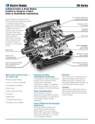
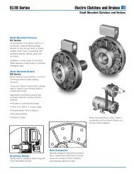
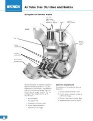
<strong>Electrically</strong> <strong>Released</strong> <strong>Brakes</strong>For Dynamic Stoppingand Cycling ApplicationsWarner Electric’s modular design brakes and clutch/brake unitsoffer material handling system users a high performancealternative to spring-set brakes. These modular units providelong life, maintenance free operation, and consistentperformance with minimal downtime.EM/EUM-FBB Features11/15/99page 166These brakes are offered in power-off types for double shaftmotors and for installation between C-face motor and reducer orother drive device. Powerful permanent magnets generatebraking torque. The brakes release when voltage is applied tothe coil, countering the force of the permanent magnets. Nopower is required to stop or hold a load. An optional integralconduit box provides simple wiring direct from the motor powerleads.• Designed for dynamic stopping operations• Brake automatically engages when power is turned off• High cycle rate capability• Never needs adjustment – automatically compensates forwear• Powerful permanent magnets provide braking force• Choice of open or enclosed brakes• Prepackaged, preburnished UM versionThree C-face Compatible DesignsThe UM Series (UniModule Clutch/<strong>Brakes</strong>) are preassembledclutch/electrically released brake modules.• The UM-1020-FBC brake/motor clutch combination is usedfor clutch/power-off brake applications. It mounts directly toC-face compatible components.• The UM-2030-FBC brake/input clutch combination is used forclutch/power-off brake applications. It has shafts on both theinput and output sides for base mounting.The EUM Series (Enclosed Motor <strong>Brakes</strong>) are totally enclosednon-vented units that keep wear particles in and contaminantsout.<strong>Permanent</strong> <strong>Magnet</strong> <strong>Modules</strong>Brake <strong>Modules</strong> (FBB) – For mounting between aC-face motor and a gearbox or reducerEM SeriesShaft mounted,vented housingUse for brake alone applications.EUM SeriesShaft mounted,totally enclosednon-vented housingFeatures• Single armature for brakealone applications• Output shaft• <strong>Permanent</strong> magnets• UL listed and CSA certifiedEM-FBBAvailable in 4 sizesEUM-FBBAvailable in 4 sizes• The EUM-FBB brake unit can be mounted between twoC-face compatible components.• The EUM-MBFB motor brake is mounted directly to the rearof a double-shafted motor.The EM Series (Electro Module <strong>Brakes</strong> and Clutch/<strong>Brakes</strong>)are comprised of individual units that may bolt together to formvarious combinations:• The EM-FBB brake module mounts between a C-face motorand a gear box or reducer.• The EM-MBFB motor brake module is mounted to the rear ofa double-shafted motor.• The EM-FBC brake module is used in combination with amotor clutch or input clutch unit to make a cluch/electricallyreleased brake or can be used alone as a brake only.EM-FBB Electro Modulebrake unit between amotor and a reducer.
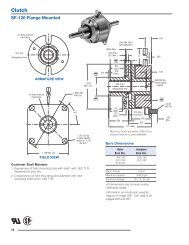
<strong>Permanent</strong> <strong>Magnet</strong> <strong>Modules</strong>Motor Brake <strong>Modules</strong> (MBFB) – For mounting directlyto the rear of a double-shafted motor<strong>Electrically</strong> <strong>Released</strong> <strong>Brakes</strong>C-face Compatible <strong>Brakes</strong>and Clutch/<strong>Brakes</strong>Clutch/Brake <strong>Modules</strong> (FBC) – Clutch/Fail-safebrake for mounting between a C-face motor and agearbox or reducerEM Seriesvented housingUse as a motor brake on C-face type motors.EUM Seriestotally enclosednon-ventedhousingEM SeriesModular unit withC/B capabilityUM SeriesFully assembled C/Bcombination packageCombine with a motor or input clutch for clutch/brakeapplications or use alone as a brake only.Features• Single armature design• Complete torque control• Precision cast housing• Ceramic type permanentmagnetsEM-MBFBAvailable in 4 sizesEUM-MBFBAvailable in 5 sizesFeatures• Dual armature forclutch/brake combination• Output shaft• Can be base mounted foruse as a separate drive unit.EM-FBCAvailable in 3 sizesUM-FBCAvailable in 4 sizecombinationsTypical mounting of anMBFB module on theback of a C-face motorEM-FBC Electro Modulebrake unit combined with amotor clutch moduleUM-FBC UniModuleclutch/brake mountedon a base
<strong>Electrically</strong> <strong>Released</strong> <strong>Brakes</strong>UniModule Clutch/<strong>Electrically</strong> <strong>Released</strong>Brake CombinationUM-FBC SeriesFan cooled for long life andconsistent performance.Completely sealed coilsNEMA C-facecompatible designEasy set screw accessSingle conduit entranceBearing mounted rotor.Heavy duty bearingsmaintain tightconcentricity andrunning efficiency.Autogaps ®automaticallyadjust for wear.High torque, long life,asbestos-freefriction materialFinned designfor maximumheat dissipation.Warner Electric offers the convenience ofpre-assembled UniModuleclutch/electrically released brake packages.Assembly, alignment, and pre-burnishinghave been done at the factory. Bolt it on,wire it up, and your clutch/electricallyreleased brake is ready to go. Available inboth C-face and base mounted versions.Warner Electric’s unique design employspowerful permanent magnets formaximum torque when power is removedfrom the brake coil. A small amount ofelectrical power applied to the brake coilnullifies the permanent magnets and thebrake releases. No springs to limit cyclerates. Never any adjustments. Nolubrication. These brakes arerecommended for dynamic cyclingoperations only.
UM-FBC SeriesUM-FBC HP/Shaft Speed Chart11/15/99page 169UniModule clutch/electrically releasedbrake units may be mounted directly toNEMA C-face motors and reducers, orcan be base mounted.1. Select Configurationa. NEMA C-face Mounting(1020 Configuration)Verify the unit will be cycled frequently.To select the correct UniModulepackage, determine the NEMA framesize of your motor and/or reducer, andchoose the corresponding sizeUniModule from the Frame SizeSelection chart. Verify torque ratings.b. Base Mounting(2030 Configuration)Verify the unit will be cycled frequently.Select the correct size module from theHorsepower vs. Shaft Speed chartbydetermining the motor horsepower andRPM at the module location. Thecorrect size UniModule is shown at theintersection of the HP and operatingspeed. For additional sizing information,refer to the technical sizing procedure(step 2).<strong>Electrically</strong> <strong>Released</strong> <strong>Brakes</strong>2. Determine TechnicalRequirementsSelectionTechnical considerations for sizing andselection are torque and heat dissipation.Each merits careful consideration,especially heat dissipation as over time,use in excessive temperatureenvironments will have an adverse effecton bearing life and coil wire insulationintegrity.Compare the calculated torquerequirement with the average dynamictorque ratings. Select a unit with adequatetorque. If the unit selected on torque isdifferent than the unit selected based onheat, select the larger size unit.Horsepower vs. vs. Shaft Shaft Speed SpeedHPSHAFT SPEED AT CLUTCH (IN RPM)100 200 300 400 500 600 700 800 900 1000 1100 1200 1500 1800 2000 2400 3000 36001/4UM-501/23/41UM-100 or UM-1801-1/223UM-210 or UM-21557-1/2Frame Size Selection and Technical Ratings ChartStatic Torque Static TorqueNEMA UniModule Brake Clutch Max. VoltageFrame Size Size lb.ft. lb. RPM DC56C/48Y182C/143TC184C/145TC213C/182TC215C/184TCUM-50* 10.5 16UM-100** 21 303600 24 or 90UM-180 21 30 3600 24 or 90UM-210 56 95 3600 24 or 90213TC/215TC UM-215 56 95 3600 24 or 90*For 56C/48Y C-frame motors 3/4 HP and smaller, the UM-100 size may be used where extended life is desirable.**The UM-100 size is recommended for motors 1 HP and larger.
<strong>Electrically</strong> <strong>Released</strong> <strong>Brakes</strong>UM-FBC Seriesa. Heat Dissipation SizingFriction surfaces slip during the initialperiod of engagement and, as a result,heat is generated. The clutch/brakeselected must have a heat dissipationrating greater than the heat generatedby the application. Therefore, in highinertia or high cycle rate applications, itis necessary to check the heatdissipation carefully. Inertia, speed andcycle rate are the required parameters.Heat dissipation requirement iscalculated as follows:E = 1.7 x WR 2 x (N/100) 2 x Fwhere:Heat Dissipation CurvesSize 50Heat Dissipation (ft. lbs./min.)Maximum Speed 3600 RPM12000100008000250° F60004000200° F200000 900 1800 2700 3600Speed (RPM)E = Heat (lb. ft./min.)WR 2 = Total reflected inertia at theclutch/brake shaft. Include theclutch/brake output inertia. (lb.ft. 2 )N = Speed in revolutions per minute.(RPM)F = Cycle rate in cycles per minute(CPM)Compare the calculated heat generatedin the application to the unit ratingsusing the heat dissipation curves. Selectthe appropriate unit that has adequateheat dissipation ability.Heat Dissipation (ft. lbs./min.)Size 100/1801800015000120009000600030000Maximum Speed 3600 RPM250° F200° F0 900 1800 2700 3600Speed (RPM)Heat Dissipation (ft. lbs./min.)Size 210/215360003000024000180001200060000Maximum Speed 3600 RPM250° F200° F0 900 1800 2700 3600Speed (RPM)
UM-FBC Series<strong>Electrically</strong> <strong>Released</strong> <strong>Brakes</strong>b. Torque SizingFor most applications, the correct sizeclutch/brake can be selected from theHorsepower vs. Shaft Speed chart onpage 117. Determine the motorhorsepower and the RPM at theclutch/brake. The correct size unit isshown at the intersection of horsepowerand shaft speed.If the static torque requirements areknown, refer to the technical ratingschart to select a unit.For some applications, the torquerequirement is determined by the timeallowed to accelerate and deceleratethe load. (This time is generally specifiedin milliseconds.) For these applications,it is necessary to determine the torquerequirement based on load inertia andthe time allowed for engagement.The torque requirements are calculatedas follows:T = (WR 2 x N) / (308 x t)where:T = Average Dynamic Torque (lb. ft.)WR 2 = Total reflected inertia at theclutch/brake shaft. Include theclutch/brake output inertia. (lb. ft. 2 )N = Speed in revolutions per minute.(RPM)t = Time allowed for the engagement(sec)Dynamic Torque (lb.ft.)Dynamic Torque (lb.ft.)Dynamic Torque (lb.ft.)Dynamic Torque (lb.ft.)C-face <strong>Electrically</strong> <strong>Released</strong>Brake Dynamic Torque CurvesSize Size 50 50 5016 1614 14Dynamic Torque (lb.ft.)12 1210 108 86 6Maximum Maximum Speed Speed 3600 3600 3600 RPM RPMStatic Static Torque Torque 10.5 10.5 lb.ft. 10.5 lb.ft. lb.ft.16141210864 4 450% 50% 50% Current Current2 2 20 0 00 0 0 900 900 900 1800 1800 1800 2700 2700 2700 3600 3600 3600Size Size 100/180 100/180Dynamic Torque (lb.ft.)Dynamic Torque (lb.ft.)Maximum Maximum Speed Speed 3600 3600 3600 RPM RPMStatic Static Torque Torque 21 21 lb.ft. lb.ft. 21 lb.ft.32 32 3228 28 2824 24 2420 20 2016 16 1612 12 12100% 100% 100% Current Current8 8 850% 50% 50% Current Current4 4 40 0 00 0 0900 900 900 1800 1800 1800 2700 2700 2700 3600 3600 3600Dynamic Torque (lb.ft.)Size Size 210/215 210/21596 96100% 100% 100% Current CurrentMaximum Maximum Speed Speed 3600 3600 3600 RPM RPMStatic Static Torque Torque 56 56 lb.ft. lb.ft. 56 lb.ft.9684 84 8472 72 7260 60 6048 48 4836 36 3650% 50% 50% Current Current100% 100% 100% Current Current24 24 2412 12 120 0 00 0 0900 900 900 1800 1800 1800 2700 2700 2700 3600 3600 3600Dynamic Torque (lb.ft.)Speed Speed Difference Difference in in RPM RPM in RPMSpeed Speed Difference Difference in in RPM RPM in RPMSpeed Speed Difference Difference in in RPM RPM in RPMC-face Clutch Dynamic TorqueCurvesDynamic Torque (lb.ft.)Dynamic Torque (lb.ft.)Size Size 50 50 50Dynamic Torque (lb.ft.)Size Size 100/180 100/180Dynamic Torque (lb.ft.)Dynamic Torque (lb.ft.)Dynamic Torque (lb.ft.)Dynamic Torque (lb.ft.)Maximum Maximum Speed Speed 3600 3600 3600 RPM RPMStatic Static Torque Torque 10.5 10.5 lb.ft. 10.5 lb.ft. lb.ft.16 16 1614 14 1412 12 1210 10Maximum Maximum Speed Speed 3600 3600 3600 RPM RPMStatic Static Torque Torque 21 21 lb.ft. lb.ft. 21 lb.ft.32 32 3228 28 2824 24 2420 20 2016 16 16100% 100% 100% Current Current12 12 128 8 850% 50% 50% Current Current4 4 40 0 00 0 0900 900 900 1800 1800 1800 2700 2700 2700 3600 3600 3600Speed Speed Difference Difference in in RPM RPM in RPMDynamic Torque (lb.ft.)10864100% 100% 100% Current Current50% 50% 50% Current Current2 2 20 0 00 0 0 900 900 900 1800 1800 1800 2700 2700 2700 3600 3600 3600Speed Speed Difference Difference in in RPM RPM in RPMSize Size 210/215 210/215 Maximum Maximum Speed Speed3600 3600 3600 RPM RPM Static Static Torque Torque 95 95 lb.ft. lb.ft. 95 lb.ft.96 96 9684 84 8472 72 7260 60 6048 48 4836 36 36100% 100% 100% Current Current24 24 2412 12 1250% 50% 50% Current Current0 0 00 0 0900 900 900 1800 1800 1800 2700 2700 2700 3600 3600 3600Dynamic Torque (lb.ft.)8 86 64 4Speed Speed Difference Difference in in RPM RPM in RPM
<strong>Electrically</strong> <strong>Released</strong> <strong>Brakes</strong>UM-FBC SeriesSpecifications (Max. Speed 3600 RPM)Component Inertia–WR 2 (lb. ft. 2 )1020 2030Nominal Weight (lbs.) Armature Rotor w/Fan Output Input Rotor w/Fan NEMASize Voltage DC 1020 2030 (both) Hub Shaft and Hub Shaft Shaft and Hub Frame Size501001802102152490249012 15 .018 .001 .001 .020 .001 .001 .020 56C/48Y16 19 .046 .002 .002 .046 .002 .002 .046 56C/48Y24182C/143TC9016 19 .046 .002 .002 .046 .002 .002 .046184C/145TC24213C/182TC36 47 .162 .016 .014 .190 .016 .015 .18390 215C/184TC249037 48 .162 .016 .016 .190 .017 .016 .183 213TC/215TC3. Select OptionsWarner Electric Enclosed Uni<strong>Modules</strong> canbe fitted with several accessories toextend their capacity and ease ofmounting.4. Select ControlAll electrically released modules require acontrol with a potentiometer that will varybrake channel output. UM-FBC unitsrequire either a CBC-300 or a CBC500/550 control.UM Combination UM Model No. Voltage DC Part No.UM-50-1020FBC 24 5370-273-037UM-50-1020FBC 90 5370-273-036UM-100-1020FBC 24 5370-273-153UM-100-1020FBC 90 5370-273-125Motor Clutch/ UM-180-1020FBC 24 5370-273-047ER Brake UM-180-1020FBC 90 5370-273-046UM-210-1020FBC 24 5371-273-013UM-210-1020FBC 90 5371-273-012UM-215-1020FBC 24 5371-273-099UM-215-1020FBC 90 5371-273-079UM-50-2030FBC 24 5370-273-042UM-50-2030FBC 90 5370-273-041UM-100-2030FBC 24 5370-273-154Input Clutch/ UM-100-2030FBC 90 5370-273-155ER Brake UM-180-2030FBC 24 5370-273-052UM-180-2030FBC 90 5370-273-051UM-210-2030FBC 24 5371-273-018UM-210-2030FBC 90 5371-273-017UM-215-2030FBC 24 5371-273-100UM-215-2030FBC 90 5371-273-101AccessoriesDescription UM Size Part No.Conduit BoxBase Mount Kitfor 2030 FBCMotor Mount Kitfor 1020 FBCUM seriesAll sizes5370-101-04250/100 5370-101-036180 5370-101-037210/215 5371-101-03950/100 5370-101-010180 5370-101-012210/215 5371-101-012How to Order1. Specify model number and voltageor the corresponding part number.2. Specify conduit box, if desired.See the Controls Section.3. Specify required control unit.See the Controls Section.Ordering ExampleUM-50-1020FBC, 90V or 5370-273-036;5370-101-042 conduit box; CBC-300control.
UM-FBC Series<strong>Electrically</strong> <strong>Released</strong> <strong>Brakes</strong>UM-1020 FBC Motor Clutch/<strong>Electrically</strong> <strong>Released</strong> BrakeFOptionalConduitBoxVA1/2" ConduitHole BothEnds1/2" Conduit HoleBoth EndsHGKMJCNDEL10MotorClutch20BrakeBNote: Conduit box is optional and is ordered separately.All dimensions are nominal, unless otherwise noted.Size A B C D E F G H J K L M N (Key)50 7.281 5.375 1.813 6.750 .625 .938 6.688 3.250 2.188 75° 5.531 4.438 3/16 x 3/16 x 1-1/4100 7.281 5.375 1.813 6.750 .625 .938 6.688 3.250 2.188 75° 5.531 4.438 3/16 x 3/16 x 1-1/4180 7.359 5.375 1.891 6.750 .875 .938 6.688 3.250 2.188 75° 5.531 4.438 3/16 x 3/16 x 1-1/4210 9.688 7.031 2.500 9.250 1.125 .625 9.688 3.250 2.188 70° 6.869 5.766 1/4 x 1/4 x 2215 10.568 7.44 3.125 9.25 1.375 1.2 9.688 3.250 2.188 70° 6.869 5.766 5/16 x 5/16 x 2Motor Mount (M)F (4) slotsEBFor use with 1020, 1040, 20, 20 FBB and 1020 FBC Combinations.ADCSize A B C D E F Part No.50/100 9.25 8.25 11.00 8.000 3.50 .797 x .406 5370-101-010180 9.25 8.25 11.00 8.000 4.50 .797 x .406 5370-101-012210/215 11.50 10.50 12.00 9.000 5.25 .750 x .406 5371-101-012
<strong>Electrically</strong> <strong>Released</strong> <strong>Brakes</strong>UM-2030 FBC Input Clutch/<strong>Electrically</strong> <strong>Released</strong> BrakeUM-2030 FBC-Input Clutch/<strong>Electrically</strong> <strong>Released</strong> Brake – Base MountedUM-FBC SeriesVBAPRTUIOptionalConduitBox1/2" ConduitHole BothEnds1/2" Conduit HoleBoth EndsQCCDSK30Input Clutch20BrakeLJHFGEFHNOMNNote: Mounting base and conduit box are optional and are orderedseparately.All dimensions are nominal, unless otherwise noted.Size A B C Min. D E F G H I J K50 6.250 10.047 1.813 .625 6.219 1.109 4.000 .344 6.688 3.500 6.844180 6.250 10.188 1.891 .875 6.219 1.109 4.000 .344 6.688 4.500 7.844210 8.516 13.766 2.500 1.125 8.938 1.469 6.000 .438 9.688 5.250 9.906Size L M N O P Q R S T U V50 2.000 6.000 .500 5.000 3.250 2.188 75° 5.531 4.438 1.125 2.203180 3.000 6.625 .813 5.000 3.250 2.188 75° 5.531 4.438 1.125 2.203210 3.375 9.000 .625 7.750 3.250 2.188 70° 6.859 5.766 1.625 2.203Base (B)E (4) SlotsFor use with 2030 FBC units.Size A B C D E F G Part No.50/100 6.000 5.000 6.219 4.000 .750 X .406 3.500 2.000 5370-101-036180 6.625 5.000 6.219 4.000 .750 X .406 4.500 3.000 5370-101-037210 9.000 7.750 8.938 6.000 .750 X .531 5.250 3.375 5371-101-019FGAD CB
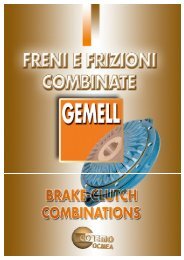
Enclosed Uni<strong>Modules</strong><strong>Electrically</strong> <strong>Released</strong> <strong>Brakes</strong>Preassembled, Totally Enclosed, <strong>Electrically</strong><strong>Released</strong> Brake UnitsRugged, casthousing providesstrengthTotally enclosedNever needsadjustment<strong>Permanent</strong>magnetsprovideholdingtorqueNEMA C-facecompatible designFBB Brake ModuleMBFB Motor Brake ModuleAvailable in Two Design StylesEUM-FBB Brake ModuleUse for brake alone applications. Mountsbetween a motor and gear box or reducer.Available in four sizes.EUM-MBFB Motor Brake ModuleMounts to a double shafted C-face motor.Available in five sizes.Warner Electric offers the convenience ofpre-assembly in UniModule electricallyreleased brake packages. Assembly, alignment,and preburnishing have been doneat the factory. Bolt it on, wire it up, andyour electrically released brake is ready togo. (Control and conduit box optional)Care must be exercised to assure propersizing and selection of electrically releasedbrakes. Motor brakes are used fordynamic stopping and holding of loadswhen power is removed from the motor.Typical applications include conveyors,process equipment, and lifting devices.Warner Electric brakes are designed forNEMA C-face motors which match themotor frame size and shaft diameter to thebrake. To select a brake, determine themotor frame size and pick an MBFB fordouble shafted motors or an FBB formounting between a motor and a gearreducer. Select the torque required for theapplication. Higher torque brakes stoploads faster. Lower torque models providesofter stopping to prevent boxes onconveyors from tipping or skidding.They are sized to provide nominalstopping of a motor in the event of powerloss. If your application requires true “Failsafe” braking, the brake must be sized tomeet or exceed peak motor torque andplaced as close to the load shaft aspossible. Peak motor torque can bedetermined by the formula:(HP x 5250)Peak Torque = Motor Speed
<strong>Electrically</strong> <strong>Released</strong> <strong>Brakes</strong>EUM-FBB, EUM-MBFB SelectionEnclosed Uni<strong>Modules</strong>Warner Electric <strong>Electrically</strong> <strong>Released</strong>Enclosed Uni<strong>Modules</strong> are available in twostyles. The EUM-FBB Brake Module isused in brake only applications andmounts between a C-face motor and agear box or reducer. The EUM-MBFBMotor Brake Module mounts to the backof a double shafted motor.Note: Care must be exercised whenselecting a brake to ensure it is sizedproperly for your application.1. Select Configurationa. FBB for NEMA C-face MountingBetween a Motor and Reducerb. MBFB for NEMA C-faceMounting on the Back of aDouble Shafted MotorVerify that the brake will be cycledfrequently.Determine the NEMA C-face frame sizeof your motor and/or reducer, andchoose the corresponding sizeEnclosed UniModule MBFB from theFrame Size Selection chart, and verifythat the motor shaft diameter andmounting bolt circle are the same for thebrake and the motor.Size EUM-100 modules utilize a 5/8"diameter shaft to fit 56C/48Y motorframes with components of EUM-180units for higher torque and heatdissipation capacity than the EUM-50.EUM-MBFB Frame Size Selection2. Determine TechnicalRequirementsTechnical considerations for sizing andselection are torque and heat dissipation.Each merits careful consideration,especially heat dissipation as over time,use in excessive temperatureenvironments will have an adverse effecton bearing life and coil wire insulationintegrity.Compare the calculated torquerequirement with the average dynamictorque ratings. Select a unit with adequatetorque. If the unit selected on torque isdifferent than the unit selected based onheat, select the larger size unit.Verify that the brake will be cycledfrequently.Determine the NEMA C-face frame sizeof your motor and/or reducer, andchoose the corresponding sizeEnclosed UniModule from the FrameSize Selection chart.Size EUM-100 modules utilize a 5/8"diameter shaft to fit 56C/48Y motorframes with components of EUM-180units for higher torque and heatdissipation capacity than the EUM-50.EUM-FBB Frame Size SelectionNEMAFrame Size56C/48Y182C/143TC184C/145TC213C/182TC215C/184TC213TC/215TCEUMSizeEUM-50*EUM-100**EUM-180EUM-210EUM-215*For 56C/48Y C-frame motors 3/4 HP andsmaller, the EUM-100 size may be usedwhere extended life is desirable.**The EUM-100 size is recommended formotors 1 HP and larger.NEMA EUM Bolt Hole Motor ShaftFrame Size Brake Size Mounting Circle Dia.56C/48Y182C/143TC184C/145TCEUM-50* 5.875 0.625EUM-100**EUM-180 5.875 0.875213C/182TC EUM-210-7/8 7.25 0.875215C/184TC EUM-210 7.25 1.125*For 56C/48Y C-frame motors 3/4 HP and smaller, the EUM-100 size may be used where extendedlife is desirable.EUM HP/SS Chart**The EUM-100 size is recommended for motors 1 HP and larger.Horsepower vs. Shaft SpeedHP1/41/23/411-1/22357-1/210SHAFT SPEED AT CLUTCH (IN RPM)100 200 300 400 500 600 700 800 900 1000 1100 1200 1500 1800 2000 2400 3000 3600EUM-210/215EUM-100/180EUM-50
Enclosed Uni<strong>Modules</strong><strong>Electrically</strong> <strong>Released</strong> <strong>Brakes</strong>a. Heat Dissipation SizingFriction surfaces slip during the initialperiod of engagement and, as a result,heat is generated. The clutch/brakeselected must have a heat dissipationrating greater than the heat generatedby the application. Therefore, in highinertia or high cycle rate applications, itis necessary to check the heatdissipation carefully. Inertia, speed andcycle rate are the required parameters.Heat Dissipation CurvesEUM 50 50 50Heat dissipation requirement iscalculated as follows:E = 1.7 x WR 2 x (N/100) 2 x Fwhere:E = Heat (lb. ft./min.)WR 2 = Total reflected inertia at theclutch/brake shaft. Include theclutch/brake output inertia. (lb.ft. 2 )N = Speed in revolutions per minute.(RPM)F = Cycle rate in cycles per minute(CPM)EUM 100/180Compare the calculated heat generatedin the application to the unit ratingsusing the heat dissipation curves. Selectthe appropriate unit that has adequateheat dissipation ability.EUM 210/215 (fan (fan (fan not not not available for for 215) for 215) 215)Heat Dissipation (lb.ft./min.)Heat Dissipation (lb.ft./min.)Heat Dissipation (lb.ft./min.)10000 100008000 8000 80006000 6000 60004000 4000 40002000 2000 2000Fan Fan Fan Cooled CooledStandard Standard0 0 0900 900 900 1800 1800 1800 2700 2700 2700 3600 3600 3600Speed Speed (RPM) (RPM)Heat Dissipation (lb.ft./min.)Heat Dissipation (lb.ft./min.)Heat Dissipation (lb.ft./min.)10000 100008000 8000 80006000 6000 60004000 4000 40002000 2000 2000Fan Fan Fan Cooled CooledStandard Standard0 0 0900 900 900 1800 1800 1800 2700 2700 2700 3600 3600 3600Speed Speed (RPM) (RPM)Heat Dissipation (lb.ft./min.)Heat Dissipation (lb.ft./min.)Heat Dissipation (lb.ft./min.)20000 2000016000 1600012000 120008000 8000 80004000 4000 4000Fan Fan Fan Cooled CooledStandard Standard0 0 0900 900 900 1800 1800 1800 2700 2700 2700 3600 3600 3600Speed Speed (RPM) (RPM)b. Torque SizingFor most applications, the correct sizeclutch/brake can be selected from theHorsepower vs. Shaft Speed chart.Determine the motor horsepower andthe RPM at the clutch/brake. Thecorrect size unit is shown at theintersection of horsepower and shaftspeed.If the static torque requirements areknown, refer to the technical ratingschart to select a unit.For some applications, the torquerequirement is determined by the timeallowed to accelerate and deceleratethe load. (This time is generally specifiedin milliseconds.) For these applications,it is necessary to determine the torquerequirement based on load inertia andthe time allowed for engagement.The torque requirements are calculatedas follows:T = (WR 2 x N) / (308 x t)where:T = Average Dynamic Torque (lb. ft.)WR 2 = Total reflected inertia at theclutch/brake shaft. Include theclutch/brake output inertia. (lb. ft. 2 )N = Speed in revolutions per minute.(RPM)t = Time allowed for the engagement(sec)C-face <strong>Electrically</strong> <strong>Released</strong> <strong>Brakes</strong> Dynamic Torque CurvesDynamic Torque (lb.ft.)Size 50Size 50Size 50 Size 100/180 Size 100/180 Size 100/180Maximum Maximum Speed 3600 Maximum Speed RPM 3600 Speed RPM 3600 RPM Maximum Maximum Speed 3600 Maximum Speed RPM3600 Speed RPM3600 RPMStatic Torque Static 10.5 Torque Static lb.ft. 10.5 Torque lb.ft. 10.5 lb.ft.Static Torque Static 21 Torque lb.ft. Static 21 Torque lb.ft. 21 lb.ft.16 16 16 32 32 329614121086Dynamic Torque (lb.ft.)14121086Dynamic Torque (lb.ft.)14121086100% Current 100% Current 100% Current28242016124 4 4850% Current50% Current50% Current2 2 240 0 000 9000 900 1800 0 900 1800 2700 1800 2700 3600 2700 3600 3600 0Dynamic Torque (lb.ft.)Dynamic Torque (lb.ft.)Size 210/215 Size 210/215 Size 210/215Maximum Maximum Speed 3600 Maximum Speed RPM3600 Speed RPM3600 RPMStatic Torque Static 56 Torque lb.ft. Static 56 Torque lb.ft. 56 lb.ft.282420161228242016100% Current 100% Current 100% Current128472604836847260483684726048368 850% Current50% Current 100% 50% Current Current 100% Current 100% Current24 24 2450% Current50% Current50% Current40401201201209000900 1800 0 900 1800 2700 1800 2700 3600 2700 3600 3600 0 9000900 1800 0 900 1800 2700 1800 2700 3600 2700 3600 3600Dynamic Torque (lb.ft.)Speed Difference Speed Difference in RPM Speed Difference in RPM in RPM Speed Difference Speed Difference in RPM Speed Difference in RPM in RPM Speed Difference Speed Difference in RPM Speed Difference in RPM in RPMDynamic Torque (lb.ft.)Dynamic Torque (lb.ft.)96Dynamic Torque (lb.ft.)96
<strong>Electrically</strong> <strong>Released</strong> <strong>Brakes</strong>Preassembled, Totally Enclosed, <strong>Electrically</strong><strong>Released</strong> Brake UnitsEnclosed Uni<strong>Modules</strong>SpecificationsComponent Inertia –WR 2 (lb.ft. 2 )Static Max. Total Armature Hub Shaft NEMASize Voltage DC Torque (lb.ft.) Speed (RPM) Weight (lbs.) (lb.ft. 2 ) Hub Shaft Spliced Input Frame Size50 90 6 3600 8.6 .009 .001 .0005 .001 .0003 56C/48Y100 90 12 3600 10.5 .023 .002 .002 .002 .002 56C/48YFBBMBFB180 90 12 3600 10.5 .023 .002 .002 .002 .002210 90 32 3600 27 .081 .016 .016 .016 .007182C/143TC184C/145TC213C/182TC215C/184TC3. Select OptionsWarner Electric Enclosed Uni<strong>Modules</strong> canbe fitted with several accessories toextend their capacity and ease ofmounting.4. Select ControlAll electrically released modules require acontrol with a potentiometer that will varybrake channel output. For FBB and MBFBbrake modules, the CBC-160, CBC-200,CBC-300, or CBC-500/550 isrecommended. The FBC units requireeither a CBC-300 or a CBC 500/550control.
Enclosed Uni<strong>Modules</strong><strong>Electrically</strong> <strong>Released</strong> <strong>Brakes</strong>Selection/Ordering InformationSelection ProcedureNote: Care must be exercised whenselecting the proper brake size for yourapplication.The selection charts list NEMA motorframe sizes, motor shaft diameters, andthe matching FBB or MBFB brakes.To select a brake:1. Determine the motor NEMA C-faceframe size.2. Select brake configurationa. FBB to mount between a NEMAC-face motor and a gear reducer.b. MBFB to mount on doubleshafted NEMA C-face motors.3. Select the brake model from thecharts by the torque required – highertorque for faster stopping, lowertorque for longer, “soft” stopping.Note: Size 100 brakes are typically usedon motors with a rating of 1 HP or greater.4. Important: Verify that the motor shaftdiameter and mounting bolt circledimensions are the same for the brakeselected and the motor.Control SelectionAn optional conduit box enclosure isavailable. All electrically released unitsrequire a control with a potentiometer tovary brake channel output. For FBB andMBFB brake modules, control modelsCBC-160, CBC-200, CBC-300, or CBC-500/550 are recommended. (See ControlsSection.)Frame SizeFBBMBFBNEMA Bolt Hole Motor to Motor BrakeEUM Size Frame Size Mounting Circle Reducer Shaft Dia. Shaft Dia.EUM-50 56C 5 7/8 5/8 5/8EUM-100 56C 5 7/8 5/8 5/8EUM-180EUM-210-7/8EUM-210EUM-215How to Order1. Specify model number and voltageor the corresponding part number.2. Specify conduit box, if desired.See the Controls Section.3. Specify required control unit.See the Controls Section.EUM Description EUM Model No. Static Torque (lb.ft.) Part No.FBBBrake Module(90VDC)143TC145TC213TC215TC182TC184TC213TC215TC5 7/8 7/8 7/87 1/4 N/A 7/87 1/4 1 1/8 1 1/87 1/4 1 3/8 N/AOrdering ExampleEUM-50-20FBB-6, 90V or 5370-169-983;5370-101-042 conduit box; CBC-160-2control.EUM-50-20FBB-6 6 5370-169-983EUM-50-20FBB-10 10.5 5370-169-986EUM-100-20FBB-12 12 5370-169-989EUM-100-20FBB-21 21 5370-169-992EUM-180-20FBB-12 12 5370-169-995EUM-180-20FBB-21 21 5370-169-998EUM-210-20FBB-32 32 5371-169-078EUM-210-20FBB-56 56 5371-169-082EUM-215-20FBB-32 32 5371-169-086EUM-215-20FBB-56 56 5371-169-090EUM-50-20MBFB-6 6 5370-169-965EUM-50-20MBFB-10 10.5 5370-169-968EUM-100-20MBFB-12 12 5370-169-971MBFB EUM-100-20MBFB-21 21 5370-169-974Motor Brake Module EUM-180-20MBFB-12 12 5370-169-977(90VDC) EUM-180-20MBFB-21 21 5370-169-980EUM-210-7/8-20MBFB-32 32 5371-169-064EUM-210-7/8-20MBFB-56 56 5371-169-068EUM-210-20MBFB-32 32 5371-169-056EUM-210-20MBFB-56 56 5371-169-060AccessoriesDescription FBB Size Part No.Conduit BoxFBB seriesAll sizes5370-101-042Motor Mount Kit 50/100/180 5370-101-012for 20 FBB 210/215 5371-101-012
<strong>Electrically</strong> <strong>Released</strong> <strong>Brakes</strong>EUM-FBB Brake ModuleEUM-FBB SeriesCBADEPOptionalConduit BoxTFNKLGHJM1/2" conduit holeboth endsSRAll dimensions are nominal, unless otherwise noted.Size A Max. B C Max. D E Max. F G Dia. H Dia.3/8-16 UNC-2A50 5.188 3.125 .500 1.000 .156 (4) Equally Spaced 6.688 .625on 5.875 Dia.3/8-16 UNC-2A100 5.266 3.125 .500 1.000 .156 (4) Equally Spaced 6.688 .625on 5.875 Dia.3/8-16 UNC-2A180 5.266 3.125 .500 1.000 .156 (4) Equally Spaced 6.688 .875on 5.875 Dia.1/2-13 UNC-2A210 7.578 4.609 .594 1.500 .313 (4) Equally Spaced 9.344 1.125on 7.250 Dia.1/2-13 UNC-2A215 7.578 4.609 .594 1.500 .313 (4) Equally Spaced 9.344 1.375on 7.250 Dia.Size J Key K Min. L Pilot Dia. M Dia. N P R S Integral Key T50 3/16 x 3/16 x 1-1/4 1.813 4.500 .625 30° 2.188 45° 3/16 x 3/16 3.125100 .3/16 x 3/16 x 1-1/4 1.891 4.500 .625 30° 2.188 45° 3/16 x 3/16 3.125180 3/16 x 3/16 x 1-1/4 1.891 4.500 .875 30° 2.188 45° 3/16 x 3/16 3.125210 1/4 x 1/4 x 2 2.500 8.500 1.125 25° 2.188 45° 1/4 x 1/4 3.125215 5/16 x 5/16 x 2 2.500 8.500 1.375 25° 2.188 45° 5/16 x 5/16 3.125
EUM-MBFB Series<strong>Electrically</strong> <strong>Released</strong> <strong>Brakes</strong>EUM-MBFB Motor Brake ModuleEABCOptionalConduit BoxJFKDIGH1/2" conduit holeboth endsAll dimensions are nominal, unless otherwise noted.HMax.Size A B C Max. D E Max. F G Dia. Dia. Length Integral Key I J K50 3.125 1.000 .156 .219 .300 3/8-16 UNC-2A 6.688 .625 2.094 3/16 x 3/16 30° 2.188 3.125100 3.125 1.000 .156 .219 .300 3/8-16 UNC-2A 6.688 .625 2.094 3/16 x 3/16 30° 2.188 3.125180 3.125 1.000 .156 .219 .500 3/8-16 UNC-2A 6.688 .875 2.063 3/16 x 3/16 30° 2.188 3.125210-7/8" 4.609 1.500 .313 .250 .594 1/2-13 UNC-2A 9.344 .875 2.766 3/16 x 3/16 30° 2.188 3.125210 4.609 1.500 .313 .250 .594 1/2-13 UNC-2A 9.344 1.125 2.766 1/4 x 1/4 30° 2.188 3.125
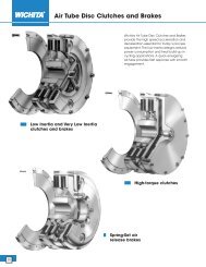
<strong>Electrically</strong> <strong>Released</strong> <strong>Brakes</strong>Electro Module, <strong>Electrically</strong> <strong>Released</strong> <strong>Brakes</strong>and Clutch/Brake Units for DynamicStopping and Cycling ApplicationsElectro <strong>Modules</strong>NEMA C-facecompatible designNever needsadjustment;automaticallycompensatesfor wear.Holding torque provided bypowerful ceramic typepermanent magnets.Complete torque control forsoft starts and stops orinstantaneous engagement.Rugged precisioncast housingBrake automaticallyengages whenpower fails.UL Listed andCSA CertifiedShaft Mounted UnitsFBB Brake ModuleFBC Brake Module for use with a clutchMBFB Motor Brake ModuleWarner Electric’s unique design employspowerful permanent magnets for maximumtorque when power is removed from thebrake coil. A small amount of electricalpower applied to the brake coil nullifies thepermanent magnets’ force and the brakereleases. No springs to limit cycle rates.Never nay adjustment. No lubrication.These brakes are recommended fordynamic cycling operations only.SpecificationsAvailable in Three Design StylesEM-FBB Brake ModuleUse for brake alone applications. Mountsbetween a C-face motor anda gear box or reducer. Available infive sizes.EM-MBFB Motor Brake ModuleMounts to the back of a double shaftedmotor. Available in four sizes.EM-FBC Brake Module for use witha ClutchCombine with a motor or input clutch forclutch/brake applications. Three sizes areavailable.Component Inertia –WR 2 (lb.ft. 2 )Static Torque (lb.ft.) Max. Total Armature NEMASize Voltage DC Brake Clutch Speed (RPM) Weight (lbs.) FBB/MBFB FBC Hub Shaft Frame SizeEM-50249010.5 16 3600 8.6 .0071 .014 .003 .001 56C/48YEM-100 90 21 — 3600 10.5 .018 — .004 .002 56C/48YEM-180EM-21024182C/143TC21 30 3600 10.5 .018 .036 .004 .00290 184C/145TC24213C/182TC56 95 3600 27 .081 .162 .027 .01790 215C/184TC
Electro <strong>Modules</strong><strong>Electrically</strong> <strong>Released</strong> <strong>Brakes</strong>EM-FBB, EM-FBC, EM-MBFB SelectionWarner Electric <strong>Electrically</strong> <strong>Released</strong>Electro <strong>Modules</strong> are available in threestyles. The EM-FBB Brake Module is usedin brake only applications and mountsbetween a C-face motor and a gear boxor reducer. The EM-MBFB Motor BrakeModule mounts to the back of a doubleshafted motor. The EM-FBC Brake Moduleis combined with a motor clutch (EM-10)or an input clutch (EM-30) forclutch/electrically released brakeapplications.Note: Care must be exercised whenselecting a brake to ensure it is sizedproperly for your application.1. Select ConfigurationEM HP/Shaft Speed Charta. For FBB and MBFB <strong>Modules</strong>NEMA C-face Mounting11/15/99page 183Size EM-100 modules utilize a 5/8"diameter shaft to fit 56C/48Y motorframes with components of EM-180units for higher torque and heatdissipation capacity than the EM-50Select Brake Configuration: use an EM-FBB for mounting between a motor anda reducer; or an EM-MBFB for mountingon the rear of a double shafted motor.NOTE: When selecting an MBFB,ensure the shaft dimensions on the rearof the motor are compatible with theEM-MBFB unit selected.b. For FBC Modular Units, NEMAC-face MountingVerify that brake will be cycledfrequently, and will be used with a motormounted clutch (EM-10) for C-facemounting.Determine the NEMA C-face frame sizeof your motor and/or reducer, andchoose the corresponding size ElectroModule from the Frame Size Selectionchart.FBC Frame Size SelectionNEMAFrame Size56C/48Y182C/143TC184C/145TC213C/182TC215C/184TCEMSizeEM-50*EM-100**EM-180EM-210For torque ratings, refer to the “Specifications”chart. Note that separate torque ratings arelisted for the clutch and brake segments of themodule.* For 56C/48Y C-frame motors 3/4 HP andsmaller, the EM-100 size may be used whereextended life is desirable.** The EM-100 size is recommended for motors1 HP and larger.c. For FBC Modular Units, BaseMountingVerify that the brake will be cycledfrequently.Determine the NEMA C-face frame sizeof your motor and/or reducer, andchoose the corresponding size ElectroModule from the Frame Size Selectionchart.FBB AND MBFB Frame SizeSelectionNEMAFrame Size56C/48Y182C/143TC184C/145TC213C/182TC215C/184TC213TC/215TCEMSizeEM-50*EM-100**EM-180EM-210EM-215*For 56C/48Y C-frame motors 3/4 HP andsmaller, the EM-100 size may be used whereextended life is desirable.**The EM-100 size is recommended for motors1 HP and larger.Horsepower vs. vs. Shaft Shaft Speed SpeedHP1/41/23/411-1/22357-1/2Verify that brake will be cycledfrequently, and will be used with aninput clutch (EM-30) for base mounting.Select the correct size module from theHorsepower vs. Shaft Speed chart (atthe bottom of this page) by determiningthe motor horsepower and RPM at themodule location. The correct size EM isshown at the intersection of the HP andoperating speed. For additional sizinginformation, refer to the technical sizingprocedure (step 2).SHAFT SPEED AT CLUTCH (IN RPM)100 200 300 400 500 600 700 800 900 1000 1100 1200 1500 1800 2000 2400 3000 3600EM-50EM-100 or EM-180EM-210 or EM-215
<strong>Electrically</strong> <strong>Released</strong> <strong>Brakes</strong>Electro <strong>Modules</strong>2. Determine TechnicalRequirementsTechnical considerations for sizing andselection are torque and heat dissipation.Each merits careful consideration,especially heat dissipation as over time,use in excessive temperatureenvironments will have an adverse effecton bearing life and coil wire insulationintegrity.Compare the calculated torquerequirement with the average dynamictorque ratings. Select a unit with adequatetorque. If the unit selected on torque isdifferent than the unit selected based onheat, select the larger size unit.a. Heat Dissipation SizingFriction surfaces slip during the initialperiod of engagement and, as a result,heat is generated. The clutch/brakeselected must have a heat dissipationrating greater than the heat generatedby the application. Therefore, in highinertia or high cycle rate applications, itis necessary to check the heatdissipation carefully. Inertia, speed andcycle rate are the required parameters.Heat dissipation requirement iscalculated as follows:E = 1.7 x WR 2 x (N/100)2 x Fwhere:E = Heat (lb. ft./min.)WR 2 = Total reflected inertia at theclutch/brake shaft. Include theclutch/brake output inertia. (lb.ft. 2 )N = Speed in revolutions per minute.(RPM)F = Cycle rate in cycles per minute(CPM)Compare the calculated heat generatedin the application to the unit ratingsusing the heat dissipation curves. Selectthe appropriate unit that has adequateheat dissipation ability.Heat Dissipation CurvesHeat Dissipation (ft. lbs./min.)Heat Dissipation (ft. lbs./min.)Heat Dissipation (ft. lbs./min.)Size 5012000100008000600040002000Size 100/1801800015000120009000600030000Size 210/215360003000024000180001200060000Maximum Speed 3600 RPMMaximum Speed 3600 RPM0 900 1800 2700 3600Speed (RPM)Maximum Speed 3600 RPM250° F200° F00 900 1800 2700 3600Speed (RPM)250° F200° F250° F200° F0 900 1800 2700 3600Speed (RPM)b. Torque SizingFor most applications, the correct sizeclutch/brake can be selected from theHorsepower vs. Shaft Speed chart onpage 131. Determine the motorhorsepower and the RPM at theclutch/brake. The correct size unit isshown at the intersection of horsepowerand shaft speed.If the static torque requirements areknown, refer to the technical ratingschart to select a unit.For some applications, the torquerequirement is determined by the timeallowed to accelerate and decelerate theload. (This time is generally specified inmilliseconds.) For these applications, it isnecessary to determine the torquerequirement based on load inertia andthe time allowed for engagement.The torque requirements are calculatedas follows:T = (WR 2 x N) / (308 x t)where:T = Average Dynamic Torque (lb. ft.)WR 2 = Total reflected inertia at theclutch/brake shaft. Include theclutch/brake output inertia. (lb. ft. 2 )N = Speed in revolutions per minute.(RPM)t = Time allowed for the engagement(sec)
Electro <strong>Modules</strong><strong>Electrically</strong> <strong>Released</strong> <strong>Brakes</strong>C-face <strong>Electrically</strong> <strong>Released</strong><strong>Brakes</strong> Dynamic Torque CurvesDynamic Torque - (lb.ft.)Dynamic Torque - (lb.ft.)Dynamic Torque - (lb.ft.)Size 50161412108642Size 100/1803228242016128400Size 210/21596Maximum Speed3600 RPM Static Torque 10.5 lb.ft.50% Current00 900 1800 2700 36008472604836241200100% CurrentSpeed Difference in RPMMaximum Speed3600 RPM Static Torque 21 lb.ft.Speed Difference in RPM50% Current900 1800 2700 3600Maximum Speed3600 RPM Static Torque 56 lb.ft.50% Current100% Current100% Current900 1800 2700 3600Speed Difference in RPM3. Select AccessoriesWarner Electric Electro <strong>Modules</strong> can befitted with several accessories to extendtheir capacity and ease of mounting.4. Select ControlAll electrically released modules require acontrol with a potentiom eter that will varybrake channel output. For FBB and MBFBbrake modules, the CBC-160, CBC-200,CBC-300, or CBC-500/550 isrecommended. The FBC units requireeither a CBC-300 or a CBC 500/550control.How to Order1. Specify model number and voltageor the corresponding part number.2. Specify conduit box, if desired. Seethe Controls Section.3. Specify required control. See theControls Section.Ordering ExampleEM-50-20FBB, 90V or 5370-169-058;5370-101-042 conduit box; CBC-160-2control.EM Description EM Model No. Voltage DC Part No.EM-50-20FBB 24 5370-169-066EM-50-20FBB 90 5370-169-058FBB EM-100-20FBB 24 5370-169-020Brake EM-100-20FBB 90 5370-169-084Module EM-180-20FBB 24 5370-169-068for use as EM-180-20FBB 90 5370-169-059brake only EM-210-20FBB 24 5371-169-032EM-210-20FBB 90 5371-169-029EM-215-20FBB 24 5371-169-100EM-215-20FBB 90 5371-169-054EM-50-20FBC 24 5370-169-065FBC EM-50-20FBC 90 5370-169-056Brake EM-100-20FBC 24 5370-169-109Module EM-100-20FBC 90 5370-169-108for use with EM-180-20FBC 24 5370-169-067EM clutch EM-180-20FBC 90 5370-169-057EM-210-20FBC 24 5371-169-031EM-210-20FBC 90 5371-169-028EM-50-20MBFB 24 5370-169-063EM-50-20MBFB 90 5370-169-060MBFB EM-100-20MBFB 24 5370-169-007Motor EM-100-20MBFB 90 5370-169-085Brake EM-180-20MBFB 24 5370-169-069Module EM-180-20MBFB 90 5370-169-061EM-210-7/8-20MBFB 24 5371-169-101EM-210-7/8-20MBFB 90 5371-169-072EM-210-20MBFB 24 5371-169-033EM-210-20MBFB 90 5371-169-030AccessoriesDescription EM Size Part No.Conduit BoxBase Mount Kitfor 2030 FBCMotor Mount Kitfor 20 FBB, 1020 FBCEM seriesAll sizes5370-101-04250/100 5370-101-036180 5370-101-037210/215 5371-101-01950/100 5370-101-010180 5370-101-012210/215 5371-101-012
<strong>Electrically</strong> <strong>Released</strong> <strong>Brakes</strong>EM-20 FBB Brake ModuleEM-FBB SeriesCBADEPFGKLN1/2" NPTHMJSRAll dimensions are nominal, unless otherwise noted.Size A Max. B C Max. D E Max. F G Dia. H Dia. J K Min. L Pilot Dia. M Dia. N P Min. R S Key3/8-16 UNC-2A 3/16 x50/100 5.188 3.125 .500 1.000 .156 (4) Equally Spaced 6.688 .625 3/16 x 1.813 4.500 .625 30° 36 45° 3/16 x 3/16on 5.875 Dia. 1-3/83/8-16 UNC-2A 3/16 x180 5.266 3.125 .500 1.000 .156 (4) Equally Spaced 6.688 .875 3/16 x 1.891 4.500 .875 30° 36 45° 3/16 x 3/16on 5.875 Dia. 1-3/81/2-13 UNC-2A 1/4 x210 7.578 4.609 .594 1.500 .313 (4) Equally Spaced 9.344 1.125 1/4 x 2.500 8.500 1.125 25° 36 45° 1/4 x 1/4on 7.250 Dia. 21/2-13 UNC-2A 5/16 x215 7.578 4.609 .594 1.500 .313 (4) Equally Spaced 9.344 1.375 5/16 x 2.500 8.500 1.375 25° 36 45° 5/16 x 5/16on 7.250 Dia. 2
EM-FBC Series<strong>Electrically</strong> <strong>Released</strong> <strong>Brakes</strong>EM-20FBC Brake Module foruse with a ClutchCBElectricalConnectionADEQFGKLP 1/2" NPTHMJSNMountingaccessoryplateRAll dimensions are nominal, unless otherwise noted.Size A Max. B C Max. D E Max. F G Dia. H Dia. J K Min. L Pilot Dia. M Dia. N Max. P Q Min. R S Key3/8-16 UNC-2A 3/16 x 3/16 x50/100 5.188 3.125 .500 1.000 .156 (4) Equally Spaced 6.688 .625 3/16 x 1.813 4.500 .625 .531 30° 36 45° 3/16on 5.875 Dia. 1-3/83/8-16 UNC-2A 3/16 x 3/16 x180 5.266 3.125 .500 1.000 .156 (4) Equally Spaced 6.688 .875 3/16 x 1.891 4.500 .875 .531 30° 36 45° 3/16on 5.875 Dia. 1-3/81/2-13 UNC-2A 1/4 x 1/4 x210 7.578 4.609 .594 1.500 .313 (4) Equally Spaced 9.344 1.125 1/4 x 2.500 8.500 1.125 .797 25° 36 45° 1/4on 7.250 Dia. 2
<strong>Electrically</strong> <strong>Released</strong> <strong>Brakes</strong>EM-20 MBFB Motor Brake ModuleEM-MBFB SeriesEABC1/2" NPTFDJIGHAll dimensions are nominal, unless otherwise noted.HSize A B C Max. D E Max. F G Dia. Diameter Max. Length Required Key Size I J Min.50/100 3.125 1.000 .156 .219 .300 3/8-16 UNC-2A 6.688 .625 2.094 3/16 x 3/16 30° 36180 3.125 1.000 .156 .219 .500 3/8-16 UNC-2A 6.688 .875 2.063 3/16 x 3/16 30° 36210-7/8" 4.609 1.500 .313 .250 .594 1/2-13 UNC-2A 9.344 .875 2.766 3/16 x 3/16 30° 36210 4.609 1.500 .313 .250 .594 1/2-13 UNC-2A 9.344 1.125 2.766 1/4 x 1/4 30° 36
NEMA Frame StandardsOrdering InformationAHSRBFESAJUAKTBBBFSpecificationsAH AJ AK BB BF ES R S T UShaft Mtg. Bolt Mtg. Flange Pilot Mtg. Bolt Keyway Depth Over Keyway Mtg. Bolt ShaftModule Size Length Center Dia. Pilot Dia. Depth Size, Qty. Length Keyway Width Ref. Dia.50 2.06 5.875 4.500 5/32100 2.06 5.875 4.500 5/32180 2.04 5.875 4.500 5/32210 2.56 7.250 8.500 5/16215 3.12 7.250 8.500 5/163/8-16 UNC4 @ 90°3/8-16 UNC4 @ 90°3/8-16 UNC4 @ 90°1/2-13 UNC4 @ 90°1/2-13 UNC4 @ 90°Note: Warner Electric <strong>Modules</strong> are designed to comply with the NEMA framestandards for mounting. Reference to each particular frame size is given in theindividual selection tables for each type of Warner Electric module.1-1/4 .517 3/16 45° .6251-1/4 .517 3/16 45° .6251-1/4 .771 3/16 45° .87 52 .986 1/4 45° 1.1252 1.201 5/16 45° 1.375
Electrical Data/Coil RatingsEC/EB-375 EC EBVoltage – DC 90 24 6 90 24 6Resistance @ 20° C – Ohms 453.5 29.3 2.10 446.8 29.3 1.96Current – Amperes .198 .82 2.85 .201 .82 3.07Watts 17 20 17 18 20 18Coil Build-up – milliseconds 62 60 59 50 60 52Coil Decay – milliseconds 13 14 15 8 14 10EC/EB-1000 EC EBVoltage – DC 90 24 6 90 24 6Resistance @ 20° C – Ohms 248.7 19.7 1.23 248.7 19.7 1.23Current – Amperes .36 1.22 4.87 .36 1.22 4.87Watts 33 29 29 33 29 29Coil Build-up – milliseconds 250 235 220 235 220 205Coil Decay – milliseconds 70 75 80 70 75 80EC/EB-475 EC EBVoltage – DC 90 24 6 90 24 6Resistance @ 20° C – Ohms 368.9 37.8 2.32 443.1 28.8 2.05Current – Amperes .244 .64 2.58 .203 .88 2.93Watts 22 15 16 18 21 18Coil Build-up – milliseconds 92 91 90 80 75 70Coil Decay – milliseconds 18 17 16 8 9 9EC/EB-1225 EC EBVoltage – DC 90 24 6 90 24 6Resistance @ 20° C – Ohms 207.3 15.1 1.04 261.7 22.3 1.33Current – Amperes .43 1.59 5.79 .34 1.08 4.5Watts 39 38 35 31 26 27Coil Build-up – milliseconds 500 490 480 460 445 435Coil Decay – milliseconds 220 230 240 190 160 140EC/EB-650 EC EBVoltage – DC 90 24 6 90 24 6Resistance @ 20° C – Ohms 225 17.7 1.16 257.2 18.3 1.24Current – Amperes .4 1.36 5.19 .35 1.3 4.84Watts 36 33 31 32 31 29Coil Build-up – milliseconds 120 115 110 112 108 105Coil Decay – milliseconds 20 20 20 12 13 14ATC, ATTC, ATB, ATTB-25 ATC ATBVoltage – DC 6 24 90 6 24 90Resistance @ 20° C – Ohms 1.37 20.2 290 1.37 20.2 290Current – Amperes 4.38 1.19 .31 4.38 1.19 .31Watts 26.3 28.6 27.9 26.3 28.6 27.9Coil Build-up – milliseconds 145 145 145 145 145 145Coil Decay – milliseconds 8 8 8 9 9 9FB/ER-375, 475, 650 FB-375 FB-475 FB-650Voltage – DC 90 24 90 24 90 24Resistance @ 20° C – Ohms 446 29 310 22 235 16Current – Amperes .201 .822 .300 1.09 .380 1.426Watts 18 19 27 26 34 34Coil Build-up – milliseconds 40 40 80 80 90 90Coil Decay – milliseconds 5 10 8 10 10 10ATC, ATTC, ATB, ATTB-55 ATC ATBVoltage – DC 6 24 90 6 24 90Resistance @ 20° C – Ohms 1.21 19.6 230 1.21 19.6 230Current – Amperes 4.96 1.22 .39 4.96 1.22 .39Watts 29.8 29.3 35.2 29.8 29.3 35.2Coil Build-up – milliseconds 200 200 200 210 210 210Coil Decay – milliseconds 20 20 20 35 35 35ER-825, 1225 ER-825 ER-1225Voltage – DC 90 35-75Resistance @ 20° C – Ohms 304 235Current – Amperes .29 .383Watts 26 35Coil Build-up – milliseconds 400 700Coil Decay – milliseconds 20 20ATC, ATTC, ATB, ATTB-115 ATC ATBVoltage – DC 6 24 90 6 24 90Resistance @ 20° C – Ohms 1.02 16.5 182 1.02 16.5 182Current – Amperes 5.91 1.46 .50 5.91 1.46 .50Watts 35.4 35 44.6 35.4 35 44.6Coil Build-up – milliseconds 145 145 145 150 150 150Coil Decay – milliseconds 40 40 40 45 45 45EC/EB-825 EC EBVoltage – DC 90 24 6 90 24 6Resistance @ 20° C – Ohms 221 20.9 1.098 223.3 20.4 1.27Current – Amperes .407 1.15 5.464 .4 1.18 4.74Watts 37 28 33 36 28 28Coil Build-up – milliseconds 225 200 180 170 170 170Coil Decay – milliseconds 130 122 115 80 75 70
Electrical Data Coil RatingsUM/EM/UMFB/EMFBUM/EMUMFB/EMFBClutch Brake Clutch Brake Clutch Brake Brake90 90 24 24 6 6 90Voltage – DC EM-50 452 452 31.8 31.8 1.86 1.86 446Resistance EM-100 392 392 26.7 26.7 1.80 1.80 310(ohms) EM-180 392 392 26.7 26.7 1.80 1.80 310EM-210/215 248 248 17.9 17.9 1.22 1.22 205EM-50 .199 .199 .755 .755 3.23 3.23 .210AmperesEM-100 .230 .230 .896 .896 3.30 3.30 .300EM-180 .230 .230 .896 .896 3.30 3.30 .300EM-210/215 .363 .363 1.34 1.34 4.90 4.90 .380EM-50 18 18 18 18 19 19 18WattsEM-100 21 21 21.5 21.5 20 20 27EM-180 21 21 21.5 21.5 20 20 27EM-210/215 33 33 32 32 30 30 34EM-50 52 53 52 53 52 53 40Build-up EM-100 72 75 72 75 72 70 80(millisecond) EM-180 72 75 72 75 72 70 80EM-210/215 120 100 120 100 110 100 90EM-50 6.2 5.0 6.2 5.0 6.5 5.0 5Decay EM-100 12 10 12 10 12 10 8(millisecond) EM-180 12 10 12 10 12 10 8EM-210/215 20 10 20 10 20 10 10Distribuidor Autorizado e Importador - Arten Freios e Embreagens Ltda.Fone: (11) 5594-8333 • Fax (11) 5589-2422 - arten@arten.com.br • www.arten.com.br