Compact Universal Controllers RWF40... - Power Equipment Company
Compact Universal Controllers RWF40... - Power Equipment Company
Compact Universal Controllers RWF40... - Power Equipment Company

You also want an ePaper? Increase the reach of your titles
YUMPU automatically turns print PDFs into web optimized ePapers that Google loves.
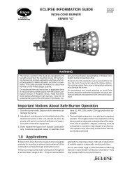
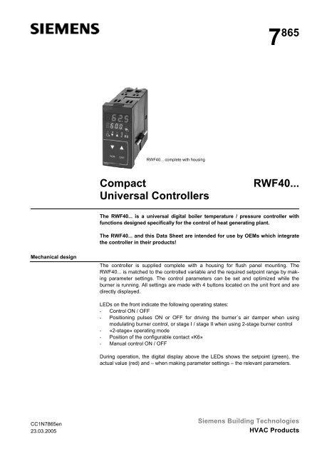
7 865<strong>RWF40.</strong>.. complete with housing<strong>Compact</strong><strong>Universal</strong> <strong>Controllers</strong><strong>RWF40.</strong>..The <strong>RWF40.</strong>.. is a universal digital boiler temperature / pressure controller withfunctions designed specifically for the control of heat generating plant.The <strong>RWF40.</strong>.. and this Data Sheet are intended for use by OEMs which integratethe controller in their products!Mechanical designThe controller is supplied complete with a housing for flush panel mounting. The<strong>RWF40.</strong>.. is matched to the controlled variable and the required setpoint range by makingparameter settings. The control parameters can be set and optimized while theburner is running. All settings are made with 4 buttons located on the unit front and aredirectly displayed.LEDs on the front indicate the following operating states:- Control ON / OFF- Positioning pulses ON or OFF for driving the burner´s air damper when usingmodulating burner control, or stage I / stage II when using 2-stage burner control- «2-stage» operating mode- Position of the configurable contact «K6»- Manual control ON / OFFDuring operation, the digital display above the LEDs shows the setpoint (green), theactual value (red) and – when making parameter settings – the relevant parameters.CC1N7865en23.03.2005Siemens Building TechnologiesHVAC Products
Warning notesTo avoid injury to persons, damage to property or the environment, the followingwarning notes should be observed!Do not open, interfere with or modify the controller!• All activities (mounting, installation and service work, etc.) must be performed byqualified staff• When selecting the cables, when making the installation and the electrical connections,observe the regulations of VDE 0100 «Erection of power installations withrated voltages below AC 1000 V» and the relevant national regulations• Provide double-pole isolation of the controller from the mains supply if there is arisk of touching live parts while work is carried out• Check to ensure that wiring is in an orderly state• Fall or shock can adversely affect the safety functions. Such units must not be putinto operation, even if they do not exhibit any damageMounting notes• Ensure that the relevant national safety regulations are complied withInstallation notes• Please observe the notes given in the user documentation CC1B7865Commissioning notes• Prior to commissioning the plant, check to ensure that wiring is in an orderly stateStandards and certificatesConformity to EEC directives- Electromagnetic compatibility EMC (immunity)- Electromagnetic compatibility EMCNAMUR recommentation89 / 336 EECNE21, EN 50 081 part 1and EN 50 082 part 2ISO 9001: 2000Cert. 00739ISO 14001: 1996Cert. 38233Service notes• For service purposes, the controller can be removed from its housing with no needfor tools• The electrical connections are made via the screw terminals located at the rear ofthe housing• Each time a unit has been replaced, check to ensure that wiring is in an orderlystate and that the wires are firmly connectedDisposal notesThe unit contains electrical and electronic components and must not be disposed oftogether with household waste.Local and currently valid legislation must be observed.2/10Siemens Building TechnologiesCC1N7865enHVAC Products 23.03.2005
Type summaryAccessoriesController with- 3-position output- housing- fixing material and sealController with- 3-position output- analog output- housing- fixing material and sealController with- 3-position output- analog output- RS-485 port- housing- fixing material and sealPackaging variants (20 pieces, without documentation)<strong>RWF40.</strong>000A97<strong>RWF40.</strong>001A97<strong>RWF40.</strong>002B97<strong>RWF40.</strong>010A97<strong>RWF40.</strong>011A97Adapter frame for replacing the RWF32...ARG40BracketFor mounting the <strong>RWF40.</strong>.. on 35 mm DIN rails to DIN 46277ARG41Dummy coverFor covering a panel cutout for the <strong>RWF40.</strong>..AVA10.200/109Demo caseFor demonstrating the functions of the <strong>RWF40.</strong>.. controllerKF88923/10Siemens Building TechnologiesCC1N7865enHVAC Products 23.03.2005
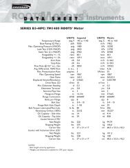
Technical dataGeneral controller dataEnvironmentalconditionsMains voltage AC 100...240 V ±10 %Mains frequency50...60 HzSafety class II to DIN 0631Mounting positionoptionalTerminals for2 x 1.5 mm² or 1 x 2.5 mm²<strong>Power</strong> consumptionapprox. 8 VASafety extra low-voltageDC 24 VContact rating of the control outputs(relays «K1...K3»)- Up to 2 x 10 5 switching cycles 2 A / AC 24...240 V- Up to 10 7 switching cycles 0.1 A / AC 24...240 VWeight complete with housingapprox. 760 gRecommended actuator running time 15...60 sDegree of protection of housing- FrontIP 65, EN 60529- BaseIP 20, EN 60529Storage DIN EN 60 721-3-1Temperature range -20...+60 °CHumidity< 75 % r.h.TransportTemperature range -40...+70 °CHumidity< 75 % r.h.OperationTemperature range -20...+50 °CHumidity< 75 % r.h.Condensation, formation of ice and ingress of water are not permitted!4/10Siemens Building TechnologiesCC1N7865enHVAC Products 23.03.2005
FunctionThe <strong>RWF40.</strong>.. provides the following functions:- One digital PID controller with a 3-position or analog output (optional)- To control 2-stage burners, the <strong>RWF40.</strong>.. can be switched over to provide 2-position control- Automatic thermostat (or pressurestat) function in low-fire operation- One shift controller for weather-dependent setpoint shifting- One minimum limiter and one maximum limiter for the boiler temperature or theboiler pressure- One limit thermostat to DIN 3440 (output 1)- One potential-free configurable contact- Manual operating mode- Communication via serial port (option)- Self-setting functionBlock structure3 analog inputsInput 1:Actual valuefor Pt100, Ni100, Pt1000,LG-Ni1000,thermocouplesor standard signalsInput 2:External setpoint,setpoint shiftingfor 0...1 k Ω resistoror linearizedstandard signalsInput 3:Outside temperaturefor Pt1000, LG-Ni10002 binary inputsFor potential-freecontactsInput 1:Operating mode changeoverInput 2:Setpoint shifting /changeover<strong>Power</strong> supplyAC 100 ...240 V,±10 %, 48...63 Hz7865f01e/0305<strong>RWF40.</strong>..Release of burnerOutput 1:- Relay (N.O. contact)Floating outputOutput 2:-Relay (actuating device open)Output 3:- Relay (actuating device closed)Limit comparatorOutput 4:- Relay (N.O. contact)<strong>Power</strong> supply measuring transducerDC 24 V, 30 mA(short-circuit proof)Analog output (optional)Output 5:Analog outputDC 0...10 V, DC 0...20 mA,DC 4...20 mASerial port (optional)RS-485MOD bus protocol5/10Siemens Building TechnologiesCC1N7865enHVAC Products 23.03.2005
Function of the controller when used for burner controlLow-fire operationIn low-fire operation, the <strong>RWF40.</strong>.. operates like a control thermostat or pressurestat.This means that it operates as a 2-position controller maintaining the required setpointby switching the burner on and off. The switching differential for 2-position operationcan be adjusted within a wide range. If the demand for heat increases, the controllerswitches to high-fire operation only when an adjustable limit is exceeded. This functionis aimed at optimizing the burner´s switching ratio.High-fire operation,2-stage controlHigh-fire operation,modulating controlBinary input 1 (changeoverof operating mode)Binary input 2 (setpointshifting or setpointchangeover)Limit comparatorOperationWeather-dependentsetpoint shiftingIn that case, the <strong>RWF40.</strong>.. operates as a 2-position controller with adjustable switchingthresholds. Using the relays of the 3-position output, the <strong>RWF40.</strong>.. drives the actuatorto the 1 st and 2 nd output stage. In this operating mode, the optional analog outputswitches between the minimum signal for the 1 st stage and the maximum output signalfor the 2 nd stage.In that case, the <strong>RWF40.</strong>.. operates as a PID / PI controller with a 3-position outputwithout position feedback signals or, optionally, with a modulating output. By makinguse of its self-setting facility, the <strong>RWF40.</strong>.. is able to determine the PID / PI controlparameters, or the parameters can be set manually.Using a potential-free contact, the <strong>RWF40.</strong>.. can be switched from the modulatingmode to 2-stage operation.In the case «setpoint shifting» is configured, the current setpoint is shifted by an adjustableamount. Configuration of «setpoint changeover» provides changeover between 2setpoints adjusted on the <strong>RWF40.</strong>.. If analog input 2 is configured for an «external setpoint»,changeover is provided between the setpoint adjusted on the <strong>RWF40.</strong>.. and anexternal setpoint.Potential-free contact «K6» can be assigned a number of functions.Example: Limit value supervision4 buttons on the unit front are used to operate and program the <strong>RWF40.</strong>.. . During operationand programming, the 7-segment displays show the parameter values and parameternames.The controller´s standard configuration ex works is such that when connecting aQAC22… outside sensor, automatic changeover to weather-dependent setpoint shiftingtakes place.The signal delivered by the QAC2... outside sensor must not be fed parallel to several<strong>RWF40.</strong>..!6/10Siemens Building TechnologiesCC1N7865enHVAC Products 23.03.2005
Function of the controller when used for burner control (cont´d)Analog input 1 (actualvalue sensor)To acquire the actual value, a number of sensors can be connected to the <strong>RWF40.</strong>..Measurement range2-or 3-wire resistance Pt100 / IEC 751-200...+850 °C (-328...+1562 °F)sensorsPt1000 / IEC 751-200...+850 °C (-328...+1562 °F)Ni100 / DIN 43760-60...+230 °C (-76...+482 °F)Ni1000 / DIN 43760-60...+230 °C (-76...+482 °F)LG-Ni1000-50...+160 °C (-58...+320 °F)Thermocouples NiCr-Ni / type «K» -200...+1372 °C (-328...+2502 °F)Cu-Cu-Ni / type «T»-200...+400 °C (-328...+752 °F)NiCroSil-NiSil / type «N»-100...+1300 °C (-148...+2372 °F)FeCuNi / type «J»-200...+1000 °C (-328...+1832 °F)Pt-RhPt / type «S» 0...1768 °C (-32...3214 °F) ¹)Pt-RhPt / type «R» 0...1768 °C (-32...3214 °F) ¹)Pt-RhPt / type «B» 0...1820 °C (32...3308 °F) ¹)Linearized standard 0...20 mA scalable -1999...+9999signals4...20 mA scalable -1999...+9999DC 0...10 V scalable -1999...+9999DC 0...1 V scalable -1999...+9999¹) Only <strong>RWF40.</strong>0X2B97The power provided for the measuring transducers is DC 24 V / 30 mA.Analog input 2 (externalsetpoint shift or externalsetpoint)Feeding a signal to analog input 2, the controller´s setpoint can be influenced. Theinfluence can be scaled.The following signals can be used:- Input signals DC 0...1 V, DC 0...10 V, 0...20 mA, 4...20 mA- 1 kΩ potentiometer in a 2-wire circuit7/10Siemens Building TechnologiesCC1N7865enHVAC Products 23.03.2005
Connection diagram (basic diagram)Temperature and pressure control on a dual-fuel burner.Burner control and supervision are provided by burner control type LAL... or LFL...NoteDC 24 V at terminals «G+» and «G-» is used for powering the QBE2000... pressuresensor!<strong>RWF40.</strong>..L N G1+ M1B9 M9 XB6 M6 Q13 Q14 Y1 Y2 Q D1 GND D2LAL..., LFL...4 5STBS18 199 11 10 20int. ext.S1BM B M1 0 2LN0IQAE...QAC...MRBSG...GASRVBV1NLKBV1vBV2aOILM z m~7865a01/1004MIN.SQ...<strong>RWF40.</strong>..L N G+ U1- M1 G- XU6 M6 Q13 Q14 Y1 Y2 Q D1 GND D2LAL..., LFL...4 5STBS18 199 11 10 20int. ext.S1GBM1 0 2QBE2000...LN0I0...10 VBSG...GASRVBV1NLKBV1vBV2aOILM z m~7865a02/1004MIN.SQ...Legenda Limit switch for air damper position OPEN QAE... Immersion temperature sensorBS Operation selector QBE... Pressure sensor1 = firing on gas RV Gas control damper(modulating burner control) S1 Internal / external setpoint switch (E)2 = firing on oil SQ... Actuator of burner´s air damper and gas(2-stage burner control)control damperBV... Fuel valve ST Connections for burner control´s startBSG... Remote setpoint adjuster (active when control loop«S1» is closed) v Auxiliary switch for the release of theL... Burner control 2 nd fuel valve depending on the air damperLK Burner´s air damper positionm (MIN) Auxiliary switch for controlling low-fire z End switch for the fully CLOSEDoperationposition of the air damperQAC... Outside sensor for weather-dependentsetpoint shifting8/10Siemens Building TechnologiesCC1N7865enHVAC Products 23.03.2005
DimensionsDimensions in mm48K69691,5PGMEXITRWF4043,5112Panel cutout to DIN 43 70045 +0,615,57865m01e/0300127,592+0,8ARG40 adapter frame7865m02/07999/10Siemens Building TechnologiesCC1N7865enHVAC Products 23.03.2005
Dimensions (cont´d)Dimensions in mmARG4194831335,57,5456068458361,415312,57865m04/100410/10© 2005 Siemens Building Technologies Production GmbHSubject to change!Siemens Building TechnologiesCC1N7865enHVAC Products 23.03.2005
Represented By:POWER EQUIPMENT COMPANY2011 Williamsburg RoadRichmond, VA 23231Ph. 804-236-3800Fx. 804-236-3882www.peconet.com