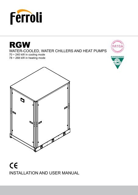
installation and user manual
installation and user manual
installation and user manual

You also want an ePaper? Increase the reach of your titles
YUMPU automatically turns print PDFs into web optimized ePapers that Google loves.
HYDRAULIC CONNECTIONS. . . . . . . . . . . . . . . . . . . . . . . . . . . . . . . . . . . . . . . . . . . . . . . . . . . . . . . . . . . . . . . . . . . . . . . . . . .46General rules . . . . . . . . . . . . . . . . . . . . . . . . . . . . . . . . . . . . . . . . . . . . . . . . . . . . . . . . . . . . . . . . . . . . . . . . . . . . . . . . . . . . 46Hydraulic layout of the system . . . . . . . . . . . . . . . . . . . . . . . . . . . . . . . . . . . . . . . . . . . . . . . . . . . . . . . . . . . . . . . . . . . . . . . 46Precautions for the Winter . . . . . . . . . . . . . . . . . . . . . . . . . . . . . . . . . . . . . . . . . . . . . . . . . . . . . . . . . . . . . . . . . . . . . . . . . . 46Hydraulic circuit for heat pump reversible water side IW-BW. . . . . . . . . . . . . . . . . . . . . . . . . . . . . . . . . . . . . . . . . . . . . . . . 47Basic diagram Basic Version VB [SOURCE SIDE]. . . . . . . . . . . . . . . . . . . . . . . . . . . . . . . . . . . . . . . . . . . . . . . . . . . . . . . 47Basic diagram Basic Version VB [USER SYSTEM SIDE] . . . . . . . . . . . . . . . . . . . . . . . . . . . . . . . . . . . . . . . . . . . . . . . . . . . . . . . 47ELECTRICAL CONNECTIONS . . . . . . . . . . . . . . . . . . . . . . . . . . . . . . . . . . . . . . . . . . . . . . . . . . . . . . . . . . . . . . . . . . . . . . . . . .49General rules . . . . . . . . . . . . . . . . . . . . . . . . . . . . . . . . . . . . . . . . . . . . . . . . . . . . . . . . . . . . . . . . . . . . . . . . . . . . . . . . . . . . 49Structure of the electric panel . . . . . . . . . . . . . . . . . . . . . . . . . . . . . . . . . . . . . . . . . . . . . . . . . . . . . . . . . . . . . . . . . . . . . . . . 49Composition of the system . . . . . . . . . . . . . . . . . . . . . . . . . . . . . . . . . . . . . . . . . . . . . . . . . . . . . . . . . . . . . . . . . . . . . . . . . . 49Electrical connections . . . . . . . . . . . . . . . . . . . . . . . . . . . . . . . . . . . . . . . . . . . . . . . . . . . . . . . . . . . . . . . . . . . . . . . . . . . . . . 49R410A PROTECTION DEVICES. . . . . . . . . . . . . . . . . . . . . . . . . . . . . . . . . . . . . . . . . . . . . . . . . . . . . . . . . . . . . . . . . . . . . . . . .52REFRIGERANT FLOW DIAGRAM - St<strong>and</strong>ard unit VB. . . . . . . . . . . . . . . . . . . . . . . . . . . . . . . . . . . . . . . . . . . . . . . . . . . .53Refrigerant flow diagram in cooling mode IR / IW / BR / BW . . . . . . . . . . . . . . . . . . . . . . . . . . . . . . . . . . . . . . . . . . . . . . . . 53Refrigerant flow diagram in cooling mode IR / IW / BR / BW with electronic valve . . . . . . . . . . . . . . . . . . . . . . . . . . . . . . . 54Refrigerant flow diagram in heating mode IP / BP . . . . . . . . . . . . . . . . . . . . . . . . . . . . . . . . . . . . . . . . . . . . . . . . . . . . . . . . 55Hydraulic diagram . . . . . . . . . . . . . . . . . . . . . . . . . . . . . . . . . . . . . . . . . . . . . . . . . . . . . . . . . . . . . . . . . . . . . . . . . . . . . . .56Hydraulic diagram unit + pumping module . . . . . . . . . . . . . . . . . . . . . . . . . . . . . . . . . . . . . . . . . . . . . . . . . . . . . . . . . . . . . . 56Hydraulic diagram unit + 2 <strong>and</strong> 3 vie valve accessory . . . . . . . . . . . . . . . . . . . . . . . . . . . . . . . . . . . . . . . . . . . . . . . . . . . . . 58USER INTERFACE . . . . . . . . . . . . . . . . . . . . . . . . . . . . . . . . . . . . . . . . . . . . . . . . . . . . . . . . . . . . . . . . . . . . . . . . . . . . . . . . . . .59Botton . . . . . . . . . . . . . . . . . . . . . . . . . . . . . . . . . . . . . . . . . . . . . . . . . . . . . . . . . . . . . . . . . . . . . . . . . . . . . . . . . . . . . . . . . . 59Display . . . . . . . . . . . . . . . . . . . . . . . . . . . . . . . . . . . . . . . . . . . . . . . . . . . . . . . . . . . . . . . . . . . . . . . . . . . . . . . . . . . . . . . . . 60Menu structure . . . . . . . . . . . . . . . . . . . . . . . . . . . . . . . . . . . . . . . . . . . . . . . . . . . . . . . . . . . . . . . . . . . . . . . . . . . . . . . . . . . 61TECHNICAL DATA CONTROLLER . . . . . . . . . . . . . . . . . . . . . . . . . . . . . . . . . . . . . . . . . . . . . . . . . . . . . . . . . . . . . . . . . . . . . .65ALARMS . . . . . . . . . . . . . . . . . . . . . . . . . . . . . . . . . . . . . . . . . . . . . . . . . . . . . . . . . . . . . . . . . . . . . . . . . . . . . . . . . . . . . . . . . . .66AVAILABLE FUNCTIONS. . . . . . . . . . . . . . . . . . . . . . . . . . . . . . . . . . . . . . . . . . . . . . . . . . . . . . . . . . . . . . . . . . . . . . . . . . . . . .69ST-BY of the unit. . . . . . . . . . . . . . . . . . . . . . . . . . . . . . . . . . . . . . . . . . . . . . . . . . . . . . . . . . . . . . . . . . . . . . . . . . . . . . . . . . 69Operation mode selection. . . . . . . . . . . . . . . . . . . . . . . . . . . . . . . . . . . . . . . . . . . . . . . . . . . . . . . . . . . . . . . . . . . . . . . . . . . 69Remote ST-BY . . . . . . . . . . . . . . . . . . . . . . . . . . . . . . . . . . . . . . . . . . . . . . . . . . . . . . . . . . . . . . . . . . . . . . . . . . . . . . . . . 69Working mode remote change-over cooling / heating . . . . . . . . . . . . . . . . . . . . . . . . . . . . . . . . . . . . . . . . . . . . . . . .693 4Set point . . . . . . . . . . . . . . . . . . . . . . . . . . . . . . . . . . . . . . . . . . . . . . . . . . . . . . . . . . . . . . . . . . . . . . . . . . . . . . . . . . . . . . . . 693 43 4Antifreeze . . . . . . . . . . . . . . . . . . . . . . . . . . . . . . . . . . . . . . . . . . . . . . . . . . . . . . . . . . . . . . . . . . . . . . . . . . . . . . . . . . . 69Supplementary electrical heating elements . . . . . . . . . . . . . . . . . . . . . . . . . . . . . . . . . . . . . . . . . . . . . . . . . . . . . . . . . 69Dinamic set point . . . . . . . . . . . . . . . . . . . . . . . . . . . . . . . . . . . . . . . . . . . . . . . . . . . . . . . . . . . . . . . . . . . . . . . . . . . . . . . . . 703 43 4Plant 3 pump 4 on-off control . . . . . . . . . . . . . . . . . . . . . . . . . . . . . . . . . . . . . . . . . . . . . . . . . . . . . . . . . . . . . . . . . . . . . . . . 70Plant pump 3 4 modulating control . . . . . . . . . . . . . . . . . . . . . . . . . . . . . . . . . . . . . . . . . . . . . . . . . . . . . . . . . . . . . . . . . . . 70Dem<strong>and</strong> limit. . . . . . . . . . . . . . . . . . . . . . . . . . . . . . . . . . . . . . . . . . . . . . . . . . . . . . . . . . . . . . . . . . . . . . . . . . . . . . . . . . . . . 70Economy function . . . . . . . . . . . . . . . . . . . . . . . . . . . . . . . . . . . . . . . . . . . . . . . . . . . . . . . . . . . . . . . . . . . . . . . . . . . . . . 71Recording hours of operation . . . . . . . . . . . . . . . . . . . . . . . . . . . . . . . . . . . . . . . . . . . . . . . . . . . . . . . . . . . . . . . . . . . . . . . . 713 4Power faliure. . . . . . . . . . . . . . . . . . . . . . . . . . . . . . . . . . . . . . . . . . . . . . . . . . . . . . . . . . . . . . . . . . . . . . . . . . . . . . . . . . . . . 71Clock. . . . . . . . . . . . . . . . . . . . . . . . . . . . . . . . . . . . . . . . . . . . . . . . . . . . . . . . . . . . . . . . . . . . . . . . . . . . . . . . . . . . . . . . . . . 71Date <strong>and</strong> hours setting . . . . . . . . . . . . . . . . . . . . . . . . . . . . . . . . . . . . . . . . . . . . . . . . . . . . . . . . . . . . . . . . . . . . . . . . . . . . . 71Source pump on-off control in cooling <strong>and</strong> heating mode . . . . . . . . . . . . . . . . . . . . . . . . . . . . . . . . . . . . . . . . . . . . . . . 723 4Source pump modulating control / 2 or 3 way valve in cooling mode . . . . . . . . . . . . . . . . . . . . . . . . . . . . . . . . . . . . . . 723 4Time scheduling . . . . . . . . . . . . . . . . . . . . . . . . . . . . . . . . . . . . . . . . . . . . . . . . . . . . . . . . . . . . . . . . . . . . . . . . . . . . . . . . . . 73PARAMETERS . . . . . . . . . . . . . . . . . . . . . . . . . . . . . . . . . . . . . . . . . . . . . . . . . . . . . . . . . . . . . . . . . . . . . . . . . . . . . . . . . . . . . .75CONFIGURABLE INPUT. . . . . . . . . . . . . . . . . . . . . . . . . . . . . . . . . . . . . . . . . . . . . . . . . . . . . . . . . . . . . . . . . . . . . . . . . . . . . . .76PROBE CHARACTERISTICS . . . . . . . . . . . . . . . . . . . . . . . . . . . . . . . . . . . . . . . . . . . . . . . . . . . . . . . . . . . . . . . . . . . . . . . . . . .77SERIAL COMUNICATION. . . . . . . . . . . . . . . . . . . . . . . . . . . . . . . . . . . . . . . . . . . . . . . . . . . . . . . . . . . . . . . . . . . . . . . . . . . . . .78Modbus address . . . . . . . . . . . . . . . . . . . . . . . . . . . . . . . . . . . . . . . . . . . . . . . . . . . . . . . . . . . . . . . . . . . . . . . . . . . . . . . . . . 79start-up . . . . . . . . . . . . . . . . . . . . . . . . . . . . . . . . . . . . . . . . . . . . . . . . . . . . . . . . . . . . . . . . . . . . . . . . . . . . . . . . . . . . . . . . . .80General Rules. . . . . . . . . . . . . . . . . . . . . . . . . . . . . . . . . . . . . . . . . . . . . . . . . . . . . . . . . . . . . . . . . . . . . . . . . . . . . . . . . . . . 80MAINTENANCE. . . . . . . . . . . . . . . . . . . . . . . . . . . . . . . . . . . . . . . . . . . . . . . . . . . . . . . . . . . . . . . . . . . . . . . . . . . . . . . . . . . . . .80General Rules. . . . . . . . . . . . . . . . . . . . . . . . . . . . . . . . . . . . . . . . . . . . . . . . . . . . . . . . . . . . . . . . . . . . . . . . . . . . . . . . . . . . 80Routine maintenance . . . . . . . . . . . . . . . . . . . . . . . . . . . . . . . . . . . . . . . . . . . . . . . . . . . . . . . . . . . . . . . . . . . . . . . . . . . . . . 80General considerations. . . . . . . . . . . . . . . . . . . . . . . . . . . . . . . . . . . . . . . . . . . . . . . . . . . . . . . . . . . . . . . . . . . . . . . . . . . . . 81SAFETY AND POLLUTION. . . . . . . . . . . . . . . . . . . . . . . . . . . . . . . . . . . . . . . . . . . . . . . . . . . . . . . . . . . . . . . . . . . . . . . . . . . . .82General recommendations about the R410A refrigerant used . . . . . . . . . . . . . . . . . . . . . . . . . . . . . . . . . . . . . . . . . . . . . . . 82First aid . . . . . . . . . . . . . . . . . . . . . . . . . . . . . . . . . . . . . . . . . . . . . . . . . . . . . . . . . . . . . . . . . . . . . . . . . . . . . . . . . . . . . . . . . 84DECLARATION OF CONFORMITY . . . . . . . . . . . . . . . . . . . . . . . . . . . . . . . . . . . . . . . . . . . . . . . . . . . . . . . . . . . . . . . . . . . . . .85The manufacturer declines all responsibility for any inaccuracies in this <strong>manual</strong> due to printing or typing errors.The manufacturer reserves the right to modify the products contents in this catalogue without previous notice.3
GENERAL SPECIFICATIONSIdentification code of the unitThe codes that identify the units are listed below <strong>and</strong> include the sequences of letters that determine the meanings for the variousversions <strong>and</strong> set-ups.RGW - IR - 70.2 - VB - AB - 0 - T - 5Unit typePower SupplyIR - Unit for <strong>installation</strong> in an Hydronic system withoperation as a Chiller.IW - Unit for <strong>installation</strong> in an Hydronic system withoperation as a Chiller <strong>and</strong> Heat Pump with thecommutation between "COOL- HEAT" obtained bymanaging the hydraulic circuit.IP - Unit for <strong>installation</strong> in an Hydronic system withoperation as a Chiller <strong>and</strong> Heat Pump reversible onrefrigerant side.BR - Water Chiller suitable for BRINE ProductionBW - Heat Pump with the commutation between"COOL- HEAT" obtained by managing the hydrauliccircuit.Water Chiller suitable for BRINE productionfrom (only in cooling mode).IP - Unit for <strong>installation</strong> in an Hydronic system withoperation as a Chiller <strong>and</strong> Heat Pump reversible onrefrigerant side suitable for BRINE production from(only in cooling mode).Unit modelN° Compressor = 2Unit versionVB - St<strong>and</strong>ard unit5 - 400V-3ph~50Hz0 - R410ACondenser optionT - sT<strong>and</strong>ard configurationType of RefrigerantAcoustic VersionAB - St<strong>and</strong>ard unitAS - Low noise unitAX - Extra low noise unitThe available special versions are described below:AB St<strong>and</strong>ard unit. The compressors are installed on rubber vibration dampers.The unit has composed by basement <strong>and</strong> framework made by sheet metal with anticorrosion treatment without any closing panels.AS Low noise unit. Allows a noise reduction of 4-5 dB.The compressors are installed on rubber vibration dampers <strong>and</strong> the unit is closed with panels made by sheet metal withanticorrosion treatment <strong>and</strong> coated with sound absorbing insulation.The AS unit reaches IP54 (protection degree) so it can be installed outdoor.AX Extra low noise unit. Allows a noise reduction of 7-8 dB.The compressors are installed on rubber vibration dampers <strong>and</strong> insulated with acoustic jackets; the unit is closed with panels madeby sheet metal with anticorrosion treatment <strong>and</strong> coated with sound absorbing insulation.The AX unit reaches IP54 (protection degree) so it can be installed outdoor.Description of the componentsComponenti principali:1. Electric control <strong>and</strong> monitoring panel. This is housed in a metal casing in which the various electrical components are positionedon one metal plate.1a. The power section includes:• Main door-locking circuit-breaker.• Fuse-holder that can be isolated with protection fuse triad for each compressor.• Fuse-holder that can be isolated with protection fuse for compressor oil heaters <strong>and</strong> antifreeze (if installed).• Control contactor for each compressor.• Contactor <strong>and</strong> magnetothermic switch to protect the pump (if installed).• Phase presence <strong>and</strong> sequence monitoring device on power supply1b. The auxiliary section includes:• Fuses on the auxiliary transformer.• Electromagnetic noise filter• Insulating <strong>and</strong> safety transformer to power the auxiliary circuit.6
GENERAL SPECIFICATIONS1c. The microprocessor monitoring section includes:• User interfacing terminal with display.• On-off key.• Operating mode selector key.• Compressor on-off display LED.• Operational mode LED• Antifreeze heaters activated indicator LED.• Source Pump/s on-off display LED• Plant Pumps on-off display LED• Check-control with fault code display• ON / St<strong>and</strong>-by remote - Summer/Winter (E/I) remote selection (IW,IP. BW, BP units only).°CMODEControl system main functions:temperature control of the water produced by the unit, compressor <strong>and</strong> pump operating hour counter, timing <strong>and</strong> cycling of start-ups,input parameters by keyboard, alarms management, operating mode change (IW, IP. BW, BP units only), dynamic set-point (climaticcontrol), scheduling <strong>and</strong> integrative heaters control.If installed the hydronic kit these functions are enabled: antifreeze with pump, start-up cycle after prolonged inactivity (antisticking), ifthe hydronic kit installed has 2 pumps there is a cycling between each pump to ensure an equivalent lifetime,Digital input functions: low pressure, high pressure, high temperature on compressor supply, phase presence <strong>and</strong> sequencemonitoring device on power supply, differential water pressure control, compressors thermal protection, pumps thermal protection,ON / St<strong>and</strong>-by remote <strong>and</strong> remote operating mode change, dem<strong>and</strong> limit <strong>and</strong> Economy function,Digital output functions: compressor start-up, pump start-up, plate heat exchanger electrical heater,remote general alarm, 4-way valve (only IP,BP unit), integrative heaters.Analogic input functions: in <strong>and</strong> out water temperature for palnt <strong>and</strong> source sides, external air temperature probe (if present).Analogic output functions: continuous control (0-10V) for 2 or 3 way valves (supplied as accessory too) or for inverter pumps forcondensing control.2. Compressors. They are the SCROLL type withorbiting coil equipped with built-in thermal protection. TheAX unit includes: an acoustic jacket for the compressors.All units are equipped with two compressors connected inpairs (1 single refrigerant circuit) which can operate at thesame time (100% cooling capacity) or individually (50%of the cooling capacity), thus adapting to the differentthermal loads of the system.3. Frame structure made of sheet metal with anticorrosiontreatment <strong>and</strong>– as option- coated with epoxy powders(RAL 7035 to ensure maximun protection against adverseweather conditions.13The image refer to IR unit Mod. 90.22b2aUNITA’ IR7
GENERAL SPECIFICATIONS4. Plant Exchanger made of brazed stainless steel plates (AISI 316). It is installed in a shell of heat-insulating material to prevent theformation of condensation <strong>and</strong> heat exchanges towards the outside. St<strong>and</strong>ard supply also includes a differential pressure switch onthe water circuit to avoid the risk of freezing if the water flow is shut off for some reason.It can be equipped with antifreeze heater.5 Unit IR <strong>and</strong> BR Source Exchanger made of brazed stainless steel plates (AISI 316).It can be equipped with antifreeze heater.Unit IW <strong>and</strong> BW Source Exchanger made of brazed stainless steel plates (AISI 316). It is installed in a shell of heat-insulatingmaterial to prevent the formation of condensation <strong>and</strong> heat exchanges towards the outside.It can be equipped with antifreeze heater.Unit IP <strong>and</strong> BP Source Exchanger made of brazed stainless steel plates (AISI 316). It is installed in a shell of heat-insulatingmaterial to prevent the formation of condensation <strong>and</strong> heat exchanges towards the outside. St<strong>and</strong>ard supply also includes adifferential pressure switch on the water circuit to avoid the risk of freezing if the water flow is shut off for some reason.It can be equipped with antifreeze heater.6. Four Way Reversing valve (IP <strong>and</strong> BP units), reverses the flow direction of the refrigerant depending on operation mode (cool/heat).Covering panels (for AS <strong>and</strong> AX units, or as accessory for AB unit), made of galvanized sheet metal, if painting option (VER)is selected the panels are provided coated with epoxidic powder paint (RAL 7035) to ensure maximun protection against adverseweather conditions.One-way valves (IP <strong>and</strong> BP units), allowing the refrigerant to pass into the appropriate exchangers, depending on the operationmode (cool/heat).884464757575910The image refer to IR unit Mod. 90.2 The image refer to IP unit Mod. 190.2UNITA IRVALVOLAMECCANICAUNITA IRVALVOLAELETTRONICA8
GENERAL SPECIFICATIONSHydraulic <strong>and</strong> chilling circuit components7. Dehydrator filter. Mechanical type. Retains impurities <strong>and</strong> traces of moisture in the circuit. Hermetic type for models 70÷90;cartridge type for models 105÷240.8. Water differential pressure switch. It is installed on the connections between the water inlet <strong>and</strong> outlet of the exchanger. It stopsthe unit if it activates.9. Thermostatic expansion valve. With external equalizer, this feeds the evaporator correctly, keeping the selected superheatdegree at a steady level.10. Electronic Expansion valve (st<strong>and</strong>ard for IP <strong>and</strong> BP units), feeds the evaporator correctly, keeping the selected superheatdegree at a steady level; it guarantees an effective <strong>and</strong> quick response to the load modifications so increasing the efficiency at partialload.Refrigerant Safety valve. Installed on the discharge pipe of the compressors, this operates if extreme faults should occur in thesystem.Liquid <strong>and</strong> moisture indicator. Signals if refrigerant is in liquid state so indicating that the refrigerant charge is correct.The indicator light also indicates the amount of moisture in the refrigerant by changing colour.Low pressure switch. With fixed setting. It is installed on the suction pipe <strong>and</strong> blocks the compressors if the operating pressuresdrop below the tolerated values. Automatically resets as the pressure increases. If it activates frequently, the unit will block <strong>and</strong> canonly be restarted by resetting via the <strong>user</strong> interface terminal.High pressure switch (n°2). With fixed setting. Are installed on the discharge pipe <strong>and</strong> blocks the compressors if the operatingpressure exceeds the tolerated values. If it activates, the unit will block <strong>and</strong> can only be restarted by resetting via the <strong>user</strong> interfaceterminal.Pressure taps: 5/16 " SAE. Allow the operating pressure of the system to be measured:compressor discharge, expansion valveinlet, compressor suction.Pressure taps: 1/4 " SAE (7/16" UNF) type with schraeder pin. Allow the charge/discharge of the refrigerant gas from the system.9
ACCESSORIES AND OPTIONAL EQUIPMENTPAN - Covering panels (M) (accessory only for AB unit), made of galvanized sheet metal, if painting option (VER) is selected thepanels are provided coated with epoxidic powder paint (RAL 7035) to ensure maximun protection against adverse weather conditions.AVG - Rubber vibration dampers (F). Consisting of 4 rubber vibration dampers to fit under the unit. Reduce the transmission of themechanical vibrations generated by the compressors <strong>and</strong> pumps during normal operation to the basement of the unit. The insulatingdegree of the vibration dampers is about 85-90%.GM - Pressure gauge unit (M). Consisting of 2 pressure gauges that display the pressure values of the refrigerant on the suction<strong>and</strong> discharge of the compressors.AV – Victaulic Connections (F) Consisting of 2 Victaulic-brackets <strong>and</strong> 2 pipe Victaulic-Welding.CV – Victaulic Elbows (F) Consisting of 2 brackets <strong>and</strong> 2 elbows Victaulic-Victaulic.VA – Water valves (F) Consisting of 2 brackets <strong>and</strong> 2 water valves Victaulic to shut-off the unit from the plant or from the source.F – Victaulic Water Filter Y (F). Consisting of 1 bracket <strong>and</strong> 1 Victaulic water filter of “Y” shape. Can be turned on <strong>and</strong> off <strong>and</strong>inspected. It prevents that machining residues (dust, swarf, etc.) in the water pipes can enter into the plate-type heat exchanger.FLS - Flow switch (F). Paddle flow switch on the water circuit to avoid the risk of freezing if the water flow is shut off for any reason.For a quick connection to the unit the accessory is completed with grooved pipe (on wich install the flow switch) <strong>and</strong> victaulic bracket.VDV 2 way valve (F). Equipped with spring return actuator managed by the unit controller (0-10V) as condensing control device forunits cooled by city-water or well-water.VTV 3 way valve (F). Equipped with actuator managed by the unit controller (0-10V) as condensing control device for units cooledby dry-cooler or geothermal probe.CR - Remote control (F). This can be used to select all the monitoring <strong>and</strong> display functions of the control unit on the machine at amaximum distance of 100 meters away. It must be installed by using a cable with three str<strong>and</strong>s or three wires in PVC of the N07-VKtype with a 1mm2 section. The transmission line must be installed in a raceway separate from any electric powering wires (230/400 V).The control unit has the following buttons:MODE key : used to select the operating modeMODEON/OFF key : used to turn the unit ON/OFF <strong>and</strong> to reset the alarms°CMode + ON/OFF keys : used to access <strong>and</strong> quit the various menu levelsUP key: scrolls forwards through the menu items or increases the value of a parameterTasto DOWN: scrolls backwards through the menu items or decreases the value of a parameter.KOP - Programmer clock (F). Allows the unit to be turned on <strong>and</strong> off depending on the programmed time setting (up to 14 switchingactions can be programmed as required throughout the 7 days of the week).TAT- High Temperature Thermostat (M). Two thermostats in series on compressors discharge pipes preserve operation not allowingtemperature to rise up than a specified fixed value.SND Outdoor Air Temperature Probe (F). It allows the climatic variation of setpoint depending on the outdoor air temperature.INT - Serial interface (M/F). Allows serial communication on RS485 via MODBUS protocolCSF - Voltage monitor <strong>and</strong> sequence meter (M). The device enables control of the correct sequence of power phases <strong>and</strong> the lackof any phase. It also ensures that the unit works within ± 10% the rated voltage (MIN=360 V - RATED=400V - MAX=440V). It blocksthe unit if the voltage is outside the limits provided for.KBT – Low temperature Kit (M). Consisting of antifreeze electrical heaters for plate heat exchangers <strong>and</strong> oil crankcase heaters forcompressors. It is particularly suggested for outdoor <strong>installation</strong> or indoor <strong>installation</strong> in rooms that during winter can reach very lowambient temperatureRAM – Compressors Suction <strong>and</strong> Discharge Ball Valves (M). (not available for IP <strong>and</strong> BP units) Consisting of 2 ball valvesinstalled on suction <strong>and</strong> discharge of the compressors: they allow an easy <strong>and</strong> quick replacement of the compressors in case of fault.NOTES: (M): only installed in the factory. (F): supplied for <strong>installation</strong> by the customer.10
ACCESSORIES AND OPTIONAL EQUIPMENTMP - Pumping Module (M). Consists of minimum 1 pump up to maximum 4 pumps.The water pumps are available on 3 levels for available pressure head: St<strong>and</strong>ard (STD), High Pressure (HP1), very high pressure(HP2).4The MP is copmposed by:1. Plant Side Pump: minimum 1 pump, maximum 2 pumps (thesecond pump is activated in case of failure of the first one). Thepump/s is protected by magnetothermic switch installed on the unitelectrical panel.2. Source Side : minimum 1 pump, maximum 2 pumps (the secondpump is activated in case of failure of the first one). The pump/s isprotected by magnetothermal switch installed on the unit electricalpanel.3. Expansion tank: This is a closed, diaphragm type chamber. Itabsorbs the variations in the volumes of water in the system causedby temperature variations.4 Water pressure gauge. Connected to the water fill pipe. Displaysthe pressure of the water in the system.- Water safety valve, It acts whenever faulty service leads to anoperating pressure in the hydraulic (set =6 bar).- Water drain valves.2b- Air vent.2a3UNITA’ IRVER Framework <strong>and</strong> panels (if present) made by sheet metal with anticorrosion treatment painted RAL7035 with epoxy powders toensure the maximum resistance to adverse weather conditions.EEV (M) Electronic Expansion valve (st<strong>and</strong>ard for IP <strong>and</strong> BP units), feeds the evaporator correctly, keeping the selected superheatdegree at a steady level; it guarantees an effective <strong>and</strong> quick response to the load modifications so increasing the efficiency at partialload.SS - Soft Starter (M). Soft starter for compressors, allows a reduction around 30/40% for the inrush current <strong>and</strong> of the vibrationstransmitted to the refrigerant pipes during the start-up phase.RIF - Capacitors for power factor corrections (M). Capacitors for power factor corrections increase power factor cos φ (>0.91)MTC - Magnetothermic switch (M). Magnetothermic switch on all loads in place of fuses.1a2aThe image refer to IR unit Mod. 190.2with MP 1P plant side <strong>and</strong> 1P source side.UNITA’ IR+ POMPE3Other power source voltage rating (contact our technical department).11
GENERAL TECHNICAL specificationGeneral technical specificationsMODELS 70.2 80.2 90.2 105.2 120.2 135.2 150.2 170.2 190.2 215.2 240.2 UMPower supply 400-3-50 V-ph-HzRefrigerant type R410A -Compressor specificationsType / capacity control SCROLL (ON-OFF) -Starting Direct -Quantity 2 N°Plant ExchangerType Aluminum fins <strong>and</strong> copper tubes -PS max. operating pressure 1000 kPaQuantity 1 N°Victaulic hydraulic connection DN65 DN65 DN65 DN65 DN65 DN65 DN65 DN65 DN65 DN65 DN65 DNTotal water capacity 3.9 4.2 4.8 5.5 5.9 6.9 7.5 8.7 9.7 11.2 12.8 lSource ExchangerType Aluminum fins <strong>and</strong> copper tubes -PS max. operating pressure 1000 kPaQuantity 1 N°Victaulic hydraulic connection DN65 DN65 DN65 DN65 DN65 DN65 DN65 DN65 DN65 DN65 DN65 DNTotal water capacity 3.9 4.2 4.8 5.5 5.9 6.9 7.5 8.7 9.7 11.2 12.8 lPumping module MPSafety valve setting 600 kPaVolume sourge chamber 24 lDefault pressure sourge chamber 150 kPaMax. operating pressure sourge chamber 800 kPaElectrical specificationsUnits without pumping moduleMODELS 70.2 80.2 90.2 105.2 120.2 135.2 150.2 170.2 190.2 215.2 240.2 UMTotal maximum load current [ FLA ] 45 51 62 68 74 82 90 105 120 142 164 ATotal maximum power input [ FLI ] 26 29 34 40 45 50 55 63 72 83 93 kWTotal maximum starting current [ MIC ] 141 166 204 256 262 309 317 355 370 454 476 A12
GENERAL TECHNICAL specificationNOMINAL performances - St<strong>and</strong>ard plantsIR unit - ChillerIRMODELS 70.2 80.2 90.2 105.2 120.2 135.2 150.2 170.2 190.2 215.2 240.2 UMCooling mode W30W7 (source: water in 30°C out 35°C / plant: water in 12°C out 7°C)Cooling capacity 69.5 78.5 91.4 104.3 117.2 132.1 146.9 168.8 190.5 214.3 238.1 kWTotal power input 16.4 18.1 21.9 25.2 28.6 32.3 36.3 41.3 46.4 53.0 59.7 kWEER 4.23 4.34 4.17 4.14 4.10 4.09 4.05 4.09 4.11 4.04 3.99 W/WPlantsideSourcesideWater flow rate 3.3 3.8 4.4 5.0 5.6 6.4 7.1 8.1 9.2 10.3 11.5 l/sWater pressure drop 47 38 40 41 44 42 45 46 48 48 49 kPaWater flow rate 4.0 4.5 5.3 6.1 6.8 7.7 8.6 9.8 11.1 12.5 13.9 l/sWater pressure drop 68 55 59 60 65 62 66 67 70 71 72 kPaData declared according to EN 14511. The values are referred to units without options <strong>and</strong> accessories.IW unit - Chiller <strong>and</strong> Heat Pump with the commutation between "COOL- HEAT"IRIPMODELS 70.2 80.2 90.2 105.2 120.2 135.2 150.2 170.2 190.2 215.2 240.2 UMCooling mode W30W7 (source: water in 30°C out 35°C / plant: water in 12°C out 7°C)Cooling capacity 69.5 78.5 91.4 104.3 117.2 132.1 146.9 168.8 190.5 214.3 238.1 kWTotal power input 16.4 18.1 21.9 25.2 28.6 32.3 36.3 41.3 46.4 53.0 59.7 kWEER 4.23 4.34 4.17 4.14 4.10 4.09 4.05 4.09 4.11 4.04 3.99 W/WPlantsideSourcesideWater flow rate 3.3 3.8 4.4 5.0 5.6 6.4 7.1 8.1 9.2 10.3 11.5 l/sWater pressure drop 47 38 40 41 44 42 45 46 48 48 49 kPaWater flow rate 4.0 4.5 5.3 6.1 6.8 7.7 8.6 9.8 11.1 12.5 13.9 l/sWater pressure drop 68 55 59 60 65 62 66 67 70 71 72 kPaHeating mode W10W45 (source: water in 10°C / plant: water in 40°C out 45°C)Heating capacity 78.7 87.6 103.8 117.9 132.1 149.2 166.5 190.7 215.0 242.3 270.6 kWTotal power input 20.6 22.5 27.1 30.9 34.8 39.2 44.1 50.2 56.5 63.8 71.4 kWCOP 3.81 3.90 3.84 3.82 3.80 3.81 3.78 3.80 3.81 3.80 3.79 W/WPlant Water flow rate 3.7 4.2 4.9 5.6 6.3 7.1 7.9 9.0 10.2 11.5 12.8 l/sside Water pressure drop 58 46 50 51 54 52 56 57 59 59 61 kPaSourcesideWater flow rate 4.0 4.5 5.3 6.1 6.8 7.7 8.6 9.8 11.1 12.5 13.9 l/sWater pressure drop 68 55 59 60 65 62 66 67 70 71 72 kPaData declared according to EN 14511. The values are referred to units without options <strong>and</strong> accessories.IP unit - Chiller <strong>and</strong> Heat Pump reversible on refrigerant sideIRIPMODELS 70.2 80.2 90.2 105.2 120.2 135.2 150.2 170.2 190.2 215.2 240.2 UMCooling mode W30W7 (source: water in 30°C out 35°C / plant: water in 12°C out 7°C)Cooling capacity 68.1 77.0 89.6 102.3 114.9 129.5 144.0 165.4 186.8 210.1 233.4 kWTotal power input 16.2 17.9 21.6 24.9 28.2 31.8 35.8 40.7 45.7 52.3 58.9 kWEER 4.20 4.31 4.14 4.11 4.07 4.07 4.03 4.07 4.09 4.02 3.96 W/WPlantsideSourcesideWater flow rate 3.3 3.7 4.3 4.9 5.5 6.2 6.9 8.0 9.0 10.1 11.2 l/sWater pressure drop 45 36 38 39 42 40 43 44 46 46 47 kPaWater flow rate 4.0 4.5 5.2 6.0 6.7 7.6 8.4 9.7 10.9 12.3 13.7 l/sWater pressure drop 66 53 56 58 62 60 64 65 68 68 70 kPaHeating mode W10W45 (source: water in 10°C / plant: water in 40°C out 45°C)Heating capacity 77.7 86.6 102.8 116.8 130.8 147.7 165.4 188.8 212.8 239.8 267.9 kWTotal power input 20.7 22.5 27.1 31.0 34.9 39.3 44.2 50.3 56.4 64.0 71.6 kWCOP 3.76 3.85 3.80 3.77 3.75 3.76 3.74 3.76 3.77 3.75 3.74 W/WPlant Water flow rate 3.7 4.1 4.9 5.5 6.2 7.0 7.8 8.9 10.1 11.4 12.7 l/sside Water pressure drop 57 45 49 50 53 51 55 56 58 58 60 kPaSourcesideWater flow rate 4.0 4.5 5.2 6.0 6.7 7.6 8.4 9.7 10.9 12.3 13.7 l/sWater pressure drop 66 53 56 58 62 60 64 65 68 68 70 kPaData declared according to EN 14511. The values are referred to units without options <strong>and</strong> accessories.13
GENERAL TECHNICAL specificationNOMINAL performances - Radiant plantsIW unit - Chiller <strong>and</strong> Heat Pump with the commutation between "COOL- HEAT"IRIPMODELS 70.2 80.2 90.2 105.2 120.2 135.2 150.2 170.2 190.2 215.2 240.2 UMCooling mode W30W18 (source: water in 30°C out 35°C / plant: water in 23°C out 18°C)Cooling capacity 94.0 105.2 121.2 140.0 158.7 178.4 197.6 227.0 257.2 288.8 321.4 kWTotal power input 18.8 20.3 24.5 28.4 32.6 36.6 41.3 47.1 53.2 60.7 68.6 kWEER 5.01 5.19 4.95 4.94 4.86 4.88 4.79 4.82 4.83 4.76 4.69 W/WPlantsideSourcesideWater flow rate 4.55 5.08 5.86 6.77 7.68 8.63 9.56 10.99 12.46 13.99 15.58 l/sWater pressure drop 87 69 71 75 82 78 82 84 89 88 90 kPaWater flow rate 5.25 5.87 6.80 7.86 8.92 10.03 11.13 12.77 14.45 16.27 18.14 l/sWater pressure drop 116 92 96 101 110 105 111 114 119 119 123 kPaHeating mode W10W35 (source: water in 10°C / plant: water in 30°C out 35°C)Heating capacity 85.2 95.8 112.3 128.3 144.5 162.9 181.5 208.1 234.8 264.9 295.2 kWTotal power input 17.9 19.4 23.5 27.2 31.0 34.9 39.3 44.9 50.6 57.8 65.3 kWCOP 4.75 4.93 4.78 4.73 4.65 4.67 4.61 4.64 4.64 4.58 4.52 W/WPlant Water flow rate 4.03 4.54 5.32 6.07 6.83 7.71 8.58 9.84 11.09 12.52 13.94 l/sside Water pressure drop 68 55 59 60 65 62 66 67 70 71 72 kPaSourcesideWater flow rate 5.25 5.87 6.80 7.86 8.92 10.03 11.13 12.77 14.45 16.27 18.14 l/sWater pressure drop 116 92 96 101 110 105 111 114 119 119 123 kPaData declared according to EN 14511. The values are referred to units without options <strong>and</strong> accessories.IP unit - Chiller <strong>and</strong> Heat Pump reversible on refrigerant sideIRIPMODELS 70.2 80.2 90.2 105.2 120.2 135.2 150.2 170.2 190.2 215.2 240.2 UMCooling mode W30W18 (source: water in 30°C out 35°C / plant: water in 23°C out 18°C)Cooling capacity 90.8 101.0 117.0 135.0 153.0 172.0 190.6 218.6 247.5 278.4 309.5 kWTotal power input 19.0 20.1 24.1 28.1 32.3 36.1 41.0 46.7 52.5 59.5 66.6 kWEER 4.79 5.01 4.85 4.80 4.74 4.77 4.65 4.69 4.72 4.68 4.65 W/WPlantsideSourcesideWater flow rate 4.40 4.87 5.65 6.52 7.40 8.31 9.22 10.58 11.98 13.48 14.99 l/sWater pressure drop 81 63 66 69 76 72 77 78 82 82 84 kPaWater flow rate 5.12 5.67 6.60 7.62 8.64 9.72 10.81 12.37 13.98 15.75 17.52 l/sWater pressure drop 110 86 90 95 103 98 105 107 111 112 114 kPaHeating mode W10W35 (source: water in 10°C / plant: water in 30°C out 35°C)Heating capacity 83.7 94.0 110.3 126.1 142.1 159.5 178.2 204.6 230.3 260.3 289.5 kWTotal power input 17.6 19.0 23.1 26.7 30.4 34.2 38.6 43.9 49.5 56.6 63.9 kWCOP 4.74 4.95 4.78 4.73 4.68 4.67 4.62 4.66 4.65 4.60 4.53 W/WPlant Water flow rate 3.96 4.45 5.22 5.97 6.72 7.55 8.43 9.68 10.88 12.30 13.68 l/sside Water pressure drop 66 53 56 58 63 59 64 65 68 68 70 kPaSourcesideWater flow rate 5.12 5.67 6.60 7.62 8.64 9.72 10.81 12.37 13.98 15.75 17.52 l/sWater pressure drop 110 86 90 95 103 98 105 107 111 112 114 kPaData declared according to EN 14511. The values are referred to units without options <strong>and</strong> accessories.15
IR-IW UNIT PERFORMANCEMod. 70.2 ÷ 105.2TWCMOD. TWE 30 35 40 45 50 55kWf kWa kWt kWf kWa kWt kWf kWa kWt kWf kWa kWt kWf kWa kWt kWf kWa kWt5 67.4 13.8 80.5 64.1 15.3 78.6 60.8 17.0 77.0 56.9 19.0 74.9 52.6 21.1 72.6 47.7 23.4 69.96 69.7 13.9 82.9 66.4 15.3 80.9 63.0 17.0 79.2 58.9 19.0 77.0 54.5 21.1 74.5 49.4 23.4 71.67 72.0 13.9 85.2 70.0 15.0 84.3 65.2 17.1 81.4 60.9 19.1 79.0 56.4 21.2 76.5 51.1 23.4 73.38 74.4 13.9 87.6 71.0 15.4 85.6 67.3 17.1 83.6 63.0 19.1 81.1 58.2 21.2 78.4 - - -9 76.7 14.0 90.0 73.2 15.4 87.9 69.5 17.1 85.8 65.0 19.1 83.2 60.1 21.2 80.3 - - -10 79.0 14.0 92.4 75.5 15.5 90.2 71.7 17.2 88.0 67.0 19.2 85.2 62.0 21.2 82.2 - - -11 81.4 14.1 94.7 77.8 15.5 92.6 73.8 17.2 90.2 69.1 19.2 87.3 63.9 21.3 84.1 - - -70.212 83.7 14.1 97.1 80.1 15.5 94.9 76.0 17.2 92.4 71.1 19.2 89.4 65.8 21.3 86.0 - - -13 86.0 14.1 99.5 82.4 15.6 97.2 78.2 17.3 94.6 73.1 19.3 91.4 67.7 21.3 87.9 - - -14 88.3 14.2 101.8 84.7 15.6 99.5 80.4 17.3 96.8 75.2 19.3 93.5 69.5 21.4 89.8 - - -15 90.7 14.2 104.2 87.0 15.7 101.9 82.5 17.4 99.0 77.2 19.3 95.6 71.4 21.4 91.7 - - -16 93.0 14.3 106.6 89.3 15.7 104.2 84.7 17.4 101.2 79.2 19.4 97.6 73.3 21.4 93.7 - - -17 95.3 14.3 108.9 91.5 15.7 106.5 86.9 17.4 103.4 81.3 19.4 99.7 75.2 21.4 95.6 - - -18 97.7 14.4 111.3 93.8 15.8 108.8 89.0 17.5 105.6 83.3 19.4 101.7 77.1 21.5 97.5 - - -5 75.0 15.1 89.4 71.4 16.8 87.4 67.8 18.7 85.6 63.5 21.0 83.5 58.9 23.4 81.1 53.5 25.9 78.16 77.5 15.2 91.9 73.9 16.8 89.9 70.3 18.8 88.1 65.9 21.0 85.8 61.1 23.4 83.3 55.6 26.0 80.27 80.0 15.2 94.5 79.0 16.8 95.0 72.7 18.8 90.5 68.2 21.1 88.2 63.3 23.4 85.6 57.7 26.0 82.48 82.5 15.3 97.0 78.9 16.9 95.0 75.1 18.9 93.0 70.5 21.1 90.5 65.5 23.5 87.8 - - -9 85.0 15.3 99.6 81.4 17.0 97.5 77.5 18.9 95.4 72.8 21.1 92.9 67.7 23.5 90.0 - - -10 87.5 15.4 102.1 83.9 17.0 100.0 79.9 18.9 97.9 75.1 21.2 95.2 69.9 23.5 92.3 - - -11 90.0 15.4 104.6 86.4 17.1 102.6 82.3 19.0 100.3 77.4 21.2 97.6 72.1 23.6 94.5 - - -80.212 92.5 15.5 107.2 88.9 17.1 105.1 84.7 19.0 102.8 79.7 21.3 99.9 74.3 23.6 96.8 - - -13 95.0 15.5 109.7 91.3 17.1 107.6 87.1 19.1 105.2 82.0 21.3 102.3 76.5 23.7 99.0 - - -14 97.5 15.5 112.3 93.8 17.2 110.2 89.5 19.1 107.7 84.4 21.3 104.6 78.7 23.7 101.3 - - -15 100.0 15.6 114.8 96.3 17.2 112.7 91.9 19.1 110.1 86.7 21.4 107.0 81.0 23.7 103.5 - - -16 102.5 15.6 117.4 98.8 17.3 115.2 94.3 19.2 112.6 89.0 21.4 109.3 83.2 23.8 105.7 - - -17 105.0 15.7 119.9 101.3 17.3 117.8 96.8 19.2 115.0 91.3 21.5 111.7 85.4 23.8 108.0 - - -18 107.5 15.7 122.4 103.8 17.4 120.3 99.2 19.3 117.5 93.6 21.5 114.0 87.6 23.8 110.2 - - -5 87.9 18.0 105.0 83.9 20.0 102.9 79.8 22.4 101.1 75.0 25.1 98.9 69.8 28.0 96.4 63.7 31.1 93.36 90.7 18.0 107.8 86.7 20.0 105.7 82.6 22.4 103.9 77.7 25.2 101.6 72.4 28.1 99.1 66.3 31.2 95.97 93.4 18.1 110.6 92.0 20.3 111.3 85.4 22.5 106.7 80.4 25.2 104.4 75.1 28.1 101.8 68.9 31.2 98.68 96.2 18.1 113.4 92.3 20.2 111.4 88.1 22.5 109.5 83.1 25.3 107.1 77.8 28.2 104.5 - - -9 98.9 18.2 116.2 95.0 20.2 114.2 90.9 22.6 112.3 85.9 25.3 109.9 80.4 28.2 107.2 - - -10 101.7 18.3 119.0 97.8 20.3 117.1 93.6 22.6 115.1 88.6 25.4 112.7 83.1 28.3 109.9 - - -11 104.5 18.3 121.9 100.6 20.3 119.9 96.4 22.7 117.9 91.3 25.4 115.4 85.8 28.3 112.6 - - -90.212 107.2 18.4 124.7 103.4 20.4 122.8 99.1 22.7 120.7 94.0 25.5 118.2 88.4 28.3 115.4 - - -13 110.0 18.4 127.5 106.2 20.4 125.6 101.9 22.8 123.5 96.7 25.5 121.0 91.1 28.4 118.1 - - -14 112.7 18.5 130.3 109.0 20.5 128.5 104.6 22.8 126.3 99.4 25.6 123.7 93.8 28.4 120.8 - - -15 115.5 18.5 133.1 111.8 20.5 131.3 107.4 22.9 129.1 102.1 25.6 126.5 96.4 28.5 123.5 - - -16 118.3 18.6 135.9 114.6 20.6 134.1 110.2 22.9 131.9 104.8 25.7 129.2 99.1 28.5 126.2 - - -17 121.0 18.6 138.7 117.4 20.6 137.0 112.9 23.0 134.8 107.6 25.7 132.0 101.8 28.6 128.9 - - -18 123.8 18.7 141.5 120.2 20.7 139.8 115.7 23.0 137.6 110.3 25.8 134.8 104.4 28.6 131.6 - - -5 99.9 20.9 119.7 95.2 23.0 117.1 90.5 25.6 114.8 84.8 28.6 112.0 78.7 31.8 108.9 71.7 35.2 105.16 103.2 20.9 123.1 98.5 23.1 120.5 93.8 25.7 118.2 88.1 28.7 115.3 81.9 31.8 112.1 74.7 35.2 108.27 106.5 21.0 126.5 105.0 23.3 127.1 97.1 25.8 121.5 91.3 28.8 118.6 85.0 31.9 115.3 77.8 35.3 111.38 109.8 21.1 129.9 105.2 23.3 127.3 100.3 25.8 124.9 94.5 28.8 121.9 88.1 32.0 118.5 - - -9 113.2 21.1 133.2 108.6 23.3 130.7 103.6 25.9 128.2 97.7 28.9 125.2 91.3 32.1 121.7 - - -10 116.5 21.2 136.6 111.9 23.4 134.1 106.9 26.0 131.6 100.9 29.0 128.4 94.4 32.1 125.0 - - -11 119.8 21.3 140.0 115.2 23.5 137.5 110.2 26.1 134.9 104.1 29.1 131.7 97.6 32.2 128.2 - - -105.212 123.1 21.4 143.4 118.6 23.6 140.9 113.5 26.1 138.3 107.3 29.1 135.0 100.7 32.3 131.4 - - -13 126.4 21.4 146.8 121.9 23.6 144.3 116.7 26.2 141.6 110.6 29.2 138.3 103.8 32.3 134.6 - - -14 129.7 21.5 150.1 125.2 23.7 147.8 120.0 26.3 145.0 113.8 29.3 141.6 107.0 32.4 137.8 - - -15 133.0 21.6 153.5 128.6 23.8 151.2 123.3 26.3 148.3 117.0 29.3 144.9 110.1 32.5 141.0 - - -16 136.3 21.7 156.9 131.9 23.8 154.6 126.6 26.4 151.7 120.2 29.4 148.1 113.3 32.6 144.2 - - -17 139.6 21.7 160.3 135.2 23.9 158.0 129.9 26.5 155.0 123.4 29.5 151.4 116.4 32.6 147.4 - - -18 142.9 21.8 163.6 138.6 24.0 161.4 133.1 26.6 158.4 126.6 29.6 154.7 119.6 32.7 150.6 - - -TWE= OUTLET PLANT water temperature (cooling mode). OUTLET SOURCE water temperature (heating mode) (°C)TWC= OUTLET SOURCE water temperature (cooling mode). OUTLET PLANT water temperature (heating mode) (°C)kWf = Cooling capacity (kW).kWa = Compressor power input (kW).kWt = Heating capacity (kW).The performances refer to a 5°C temperature difference between the water entering <strong>and</strong> leaving the heat exchangers. Has also been considered A0.44 x 10 -4 m 2 K/W fouling factor.The performances are declared no considering any correction due to water flow rate <strong>and</strong> water side pressure drop (gross performance).16
IR-IW UNIT PERFORMANCEMod. 120.2 ÷ 170.2TWCMOD. TWE 30 35 40 45 50 55kWf kWa kWt kWf kWa kWt kWf kWa kWt kWf kWa kWt kWf kWa kWt kWf kWa kWt5 112.0 23.7 134.5 106.6 26.1 131.4 101.3 28.9 128.7 94.8 32.1 125.3 87.9 35.5 121.6 79.9 39.2 117.16 115.8 23.8 138.4 110.5 26.1 135.3 105.1 28.9 132.5 98.5 32.2 129.1 91.5 35.6 125.3 83.3 39.3 120.67 119.7 23.9 142.4 118.0 26.3 143.0 108.8 29.0 136.4 102.2 32.3 132.9 95.0 35.7 128.9 86.7 39.4 124.18 123.6 23.9 146.3 118.2 26.3 143.2 112.6 29.1 140.3 105.9 32.4 136.6 98.6 35.8 132.6 - - -9 127.4 24.0 150.2 122.1 26.4 147.2 116.4 29.2 144.2 109.6 32.5 140.4 102.2 35.9 136.2 - - -10 131.3 24.1 154.2 126.0 26.5 151.2 120.2 29.3 148.0 113.3 32.5 144.2 105.7 36.0 139.9 - - -11 135.2 24.2 158.1 129.9 26.6 155.1 124.0 29.4 151.9 116.9 32.6 147.9 109.3 36.1 143.6 - - -120.212 139.0 24.3 162.1 133.8 26.6 159.1 127.8 29.5 155.8 120.6 32.7 151.7 112.9 36.2 147.2 - - -13 142.9 24.3 166.0 137.6 26.7 163.0 131.6 29.5 159.6 124.3 32.8 155.5 116.4 36.3 150.9 - - -14 146.8 24.4 170.0 141.5 26.8 167.0 135.4 29.6 163.5 128.0 32.9 159.2 120.0 36.3 154.5 - - -15 150.6 24.5 173.9 145.4 26.9 170.9 139.2 29.7 167.4 131.7 33.0 163.0 123.6 36.4 158.2 - - -16 154.5 24.6 177.8 149.3 27.0 174.9 142.9 29.8 171.3 135.4 33.1 166.8 127.1 36.5 161.8 - - -17 158.4 24.7 181.8 153.1 27.1 178.9 146.7 29.9 175.1 139.0 33.2 170.6 130.7 36.6 165.5 - - -18 162.2 24.7 185.7 157.0 27.1 182.8 150.5 30.0 179.0 142.7 33.3 174.3 134.3 36.7 169.2 - - -5 126.3 26.8 151.8 120.4 29.5 148.4 114.5 32.6 145.5 107.3 36.3 141.8 99.6 40.1 137.7 90.7 44.2 132.76 130.7 26.9 156.2 124.7 29.6 152.8 118.6 32.7 149.7 111.3 36.4 145.9 103.4 40.2 141.6 94.3 44.3 136.47 135.0 27.0 160.7 133.0 29.8 161.3 122.8 32.8 154.0 115.3 36.4 150.0 107.3 40.3 145.5 97.9 44.4 140.18 139.4 27.1 165.1 133.4 29.8 161.6 127.0 32.9 158.2 119.4 36.5 154.1 111.1 40.4 149.4 - - -9 143.7 27.2 169.5 137.7 29.8 166.0 131.2 33.0 162.5 123.4 36.6 158.1 114.9 40.5 153.3 - - -10 148.0 27.3 173.9 142.0 29.9 170.4 135.3 33.1 166.8 127.4 36.7 162.2 118.7 40.5 157.2 - - -11 152.4 27.3 178.4 146.3 30.0 174.8 139.5 33.2 171.0 131.4 36.8 166.3 122.5 40.6 161.1 - - -135.212 156.7 27.4 182.8 150.6 30.1 179.2 143.7 33.2 175.3 135.4 36.9 170.4 126.3 40.7 165.0 - - -13 161.1 27.5 187.2 155.0 30.2 183.6 147.9 33.3 179.5 139.4 37.0 174.5 130.2 40.8 168.9 - - -14 165.4 27.6 191.7 159.3 30.3 188.0 152.0 33.4 183.8 143.4 37.1 178.6 134.0 40.9 172.8 - - -15 169.8 27.7 196.1 163.6 30.4 192.4 156.2 33.5 188.1 147.4 37.1 182.7 137.8 41.0 176.7 - - -16 174.1 27.8 200.5 167.9 30.5 196.8 160.4 33.6 192.3 151.4 37.2 186.8 141.6 41.1 180.6 - - -17 178.4 27.9 204.9 172.2 30.5 201.2 164.6 33.7 196.6 155.4 37.3 190.9 145.4 41.2 184.5 - - -18 182.8 28.0 209.4 176.6 30.6 205.7 168.8 33.8 200.8 159.4 37.4 194.9 149.3 41.2 188.4 - - -5 140.8 30.2 169.5 134.3 33.1 165.7 127.7 36.6 162.5 119.8 40.6 158.4 111.3 44.8 153.9 101.5 49.4 148.46 145.6 30.3 174.4 139.0 33.2 170.6 132.3 36.7 167.1 124.2 40.7 162.8 115.4 44.9 158.1 105.3 49.4 152.37 150.4 30.4 179.3 148.0 33.3 179.6 136.8 36.8 171.8 128.5 40.8 167.2 119.5 45.0 162.2 109.1 49.5 156.18 155.2 30.5 184.2 148.5 33.4 180.2 141.3 36.9 176.4 132.8 40.9 171.6 123.6 45.1 166.4 - - -9 159.9 30.6 189.0 153.2 33.6 185.1 145.9 37.0 181.0 137.1 41.0 176.1 127.6 45.2 170.6 - - -10 164.7 30.7 193.9 157.9 33.7 189.9 150.4 37.1 185.7 141.4 41.1 180.5 131.7 45.3 174.7 - - -11 169.5 30.9 198.8 162.6 33.8 194.7 155.0 37.2 190.3 145.8 41.2 184.9 135.8 45.4 178.9 - - -150.212 174.3 31.0 203.7 167.4 33.9 199.6 159.5 37.3 195.0 150.1 41.3 189.3 139.9 45.4 183.0 - - -13 179.0 31.1 208.6 172.1 34.0 204.4 164.1 37.4 199.6 154.4 41.4 193.7 143.9 45.5 187.2 - - -14 183.8 31.2 213.5 176.8 34.1 209.2 168.6 37.5 204.2 158.7 41.5 198.1 148.0 45.6 191.4 - - -15 188.6 31.3 218.3 181.6 34.2 214.1 173.1 37.6 208.9 163.0 41.6 202.5 152.1 45.7 195.5 - - -16 193.4 31.4 223.2 186.3 34.3 218.9 177.7 37.7 213.5 167.4 41.7 206.9 156.2 45.8 199.7 - - -17 198.1 31.5 228.1 191.0 34.4 223.7 182.2 37.8 218.2 171.7 41.8 211.4 160.3 45.9 203.9 - - -18 202.9 31.6 233.0 195.7 34.5 228.5 186.8 37.9 222.8 176.0 41.8 215.8 164.3 46.0 208.0 - - -5 161.4 34.3 194.1 154.0 37.7 189.8 146.5 41.6 186.0 137.6 46.2 181.4 127.8 50.9 176.2 116.7 56.1 170.06 167.0 34.5 199.7 159.4 37.8 195.3 151.8 41.7 191.4 142.6 46.3 186.5 132.6 51.1 181.1 121.1 56.2 174.57 172.5 34.6 205.3 170.0 37.8 205.9 157.0 41.8 196.8 147.6 46.4 191.6 137.3 51.2 185.9 125.5 56.3 179.08 178.0 34.7 210.9 170.4 38.0 206.5 162.3 41.9 202.1 152.6 46.5 196.7 142.0 51.3 190.8 - - -9 183.5 34.8 216.6 175.8 38.1 212.1 167.5 42.1 207.5 157.6 46.6 201.9 146.8 51.4 195.6 - - -10 189.0 34.9 222.2 181.3 38.3 217.6 172.8 42.2 212.9 162.6 46.7 207.0 151.5 51.5 200.4 - - -11 194.5 35.1 227.8 186.8 38.4 223.2 178.0 42.3 218.2 167.6 46.8 212.1 156.2 51.6 205.3 - - -170.212 200.1 35.2 233.5 192.2 38.5 228.8 183.3 42.4 223.6 172.6 47.0 217.2 161.0 51.7 210.1 - - -13 205.6 35.3 239.1 197.7 38.6 234.4 188.5 42.5 229.0 177.6 47.1 222.3 165.7 51.9 215.0 - - -14 211.1 35.4 244.7 203.1 38.7 240.0 193.8 42.7 234.3 182.6 47.2 227.4 170.4 52.0 219.8 - - -15 216.6 35.5 250.4 208.6 38.9 245.5 199.1 42.8 239.7 187.6 47.3 232.5 175.2 52.1 224.6 - - -16 222.1 35.7 256.0 214.1 39.0 251.1 204.3 42.9 245.1 192.6 47.4 237.6 179.9 52.2 229.5 - - -17 227.6 35.8 261.6 219.5 39.1 256.7 209.6 43.0 250.4 197.6 47.5 242.8 184.6 52.3 234.3 - - -18 233.2 35.9 267.3 225.0 39.2 262.3 214.8 43.1 255.8 202.6 47.7 247.9 189.4 52.4 239.2 - - -TWE= OUTLET PLANT water temperature (cooling mode). OUTLET SOURCE water temperature (heating mode) (°C)TWC= OUTLET SOURCE water temperature (cooling mode). OUTLET PLANT water temperature (heating mode) (°C)kWf = Cooling capacity (kW).kWa = Compressor power input (kW).kWt = Heating capacity (kW).The performances refer to a 5°C temperature difference between the water entering <strong>and</strong> leaving the heat exchangers. Has also been considered A0.44 x 10 -4 m 2 K/W fouling factor.The performances are declared no considering any correction due to water flow rate <strong>and</strong> water side pressure drop (gross performance).17
IP UNIT PERFORMANCEMod. 70.2 ÷ 105.2MOD.70.280.290.2105.2TWCTWE 30 35 40 45 50 55kWf kWa kWt kWf kWa kWt kWf kWa kWt kWf kWa kWt kWf kWa kWt kWf kWa kWt5 66.1 13.9 79.4 62.9 15.4 77.5 59.7 17.1 75.9 55.8 19.1 73.9 51.6 21.2 71.7 46.8 23.4 69.06 68.4 14.0 81.7 65.1 15.4 79.8 61.8 17.1 78.1 57.8 19.1 76.0 53.5 21.2 73.6 48.4 23.5 70.77 70.7 14.0 84.0 68.6 14.9 82.8 63.9 17.2 80.2 59.8 19.2 78.0 55.3 21.2 75.5 50.1 23.5 72.48 73.0 14.1 86.3 69.6 15.5 84.4 66.1 17.2 82.4 61.8 19.2 80.0 57.1 21.3 77.4 - - -9 75.2 14.1 88.6 71.9 15.6 86.6 68.2 17.3 84.6 63.8 19.2 82.0 59.0 21.3 79.2 - - -10 77.5 14.2 91.0 74.1 15.6 88.9 70.3 17.3 86.7 65.8 19.3 84.1 60.8 21.3 81.1 - - -11 79.8 14.2 93.3 76.3 15.6 91.2 72.4 17.3 88.9 67.8 19.3 86.1 62.7 21.4 83.0 - - -12 82.1 14.2 95.6 78.6 15.7 93.5 74.6 17.4 91.1 69.7 19.3 88.1 64.5 21.4 84.8 - - -13 84.4 14.3 97.9 80.8 15.7 95.7 76.7 17.4 93.2 71.7 19.3 90.1 66.4 21.4 86.7 - - -14 86.6 14.3 100.2 83.1 15.7 98.0 78.8 17.4 95.4 73.7 19.4 92.1 68.2 21.4 88.6 - - -15 88.9 14.4 102.6 85.3 15.8 100.3 80.9 17.5 97.5 75.7 19.4 94.2 70.1 21.5 90.5 - - -16 91.2 14.4 104.9 87.5 15.8 102.6 83.1 17.5 99.7 77.7 19.4 96.2 71.9 21.5 92.3 - - -17 93.5 14.4 107.2 89.8 15.9 104.9 85.2 17.5 101.9 79.7 19.5 98.2 73.8 21.5 94.2 - - -18 95.8 14.5 109.5 92.0 15.9 107.1 87.3 17.6 104.0 81.7 19.5 100.2 75.6 21.5 96.1 - - -5 73.8 15.3 88.3 70.3 16.9 86.4 66.8 18.8 84.7 62.6 21.1 82.6 58.0 23.4 80.2 52.7 25.9 77.46 76.3 15.3 90.8 72.7 17.0 88.8 69.1 18.9 87.1 64.8 21.1 84.9 60.2 23.5 82.4 54.8 26.0 79.57 78.7 15.4 93.3 77.4 16.6 93.2 71.5 18.9 89.5 67.1 21.1 87.2 62.3 23.5 84.6 56.8 26.0 81.58 81.2 15.4 95.8 77.6 17.0 93.8 73.9 19.0 91.9 69.4 21.2 89.5 64.5 23.5 86.8 - - -9 83.6 15.5 98.3 80.1 17.1 96.3 76.2 19.0 94.3 71.6 21.2 91.8 66.6 23.6 89.0 - - -10 86.0 15.5 100.8 82.5 17.1 98.8 78.6 19.0 96.7 73.9 21.3 94.1 68.8 23.6 91.2 - - -11 88.5 15.6 103.3 84.9 17.2 101.2 80.9 19.1 99.1 76.2 21.3 96.4 71.0 23.6 93.4 - - -12 90.9 15.6 105.8 87.4 17.2 103.7 83.3 19.1 101.5 78.4 21.3 98.7 73.1 23.7 95.6 - - -13 93.4 15.6 108.3 89.8 17.3 106.2 85.7 19.2 103.9 80.7 21.4 101.0 75.3 23.7 97.8 - - -14 95.8 15.7 110.8 92.2 17.3 108.7 88.0 19.2 106.3 83.0 21.4 103.3 77.5 23.7 100.0 - - -15 98.3 15.7 113.2 94.7 17.4 111.2 90.4 19.3 108.7 85.2 21.5 105.6 79.6 23.8 102.2 - - -16 100.7 15.8 115.7 97.1 17.4 113.6 92.7 19.3 111.1 87.5 21.5 107.9 81.8 23.8 104.4 - - -17 103.2 15.8 118.2 99.6 17.4 116.1 95.1 19.3 113.5 89.7 21.5 110.2 84.0 23.8 106.6 - - -18 105.6 15.9 120.7 102.0 17.5 118.6 97.5 19.4 115.9 92.0 21.6 112.5 86.1 23.9 108.8 - - -5 86.6 18.2 103.8 82.6 20.2 101.8 78.6 22.5 100.1 73.9 25.3 97.9 68.8 28.1 95.5 62.8 31.2 92.56 89.3 18.3 106.6 85.3 20.3 104.6 81.3 22.6 102.8 76.6 25.3 100.6 71.4 28.2 98.2 65.4 31.3 95.17 92.0 18.3 109.4 90.2 20.1 109.3 84.0 22.6 105.6 79.2 25.4 103.3 74.0 28.2 100.8 68.0 31.3 97.78 94.7 18.4 112.1 90.8 20.4 110.1 86.7 22.7 108.3 81.9 25.4 106.0 76.6 28.3 103.5 - - -9 97.4 18.4 114.9 93.5 20.4 112.9 89.5 22.8 111.1 84.5 25.5 108.7 79.2 28.3 106.1 - - -10 100.1 18.5 117.6 96.3 20.5 115.7 92.2 22.8 113.8 87.2 25.5 111.4 81.8 28.4 108.8 - - -11 102.8 18.5 120.4 99.0 20.5 118.5 94.9 22.9 116.6 89.9 25.6 114.1 84.4 28.4 111.4 - - -12 105.5 18.6 123.1 101.8 20.6 121.3 97.6 22.9 119.3 92.5 25.6 116.9 87.1 28.5 114.1 - - -13 108.2 18.6 125.9 104.5 20.6 124.1 100.3 23.0 122.1 95.2 25.7 119.6 89.7 28.5 116.8 - - -14 110.9 18.7 128.7 107.2 20.7 126.9 103.0 23.0 124.8 97.8 25.7 122.3 92.3 28.6 119.4 - - -15 113.6 18.8 131.4 110.0 20.7 129.7 105.7 23.1 127.6 100.5 25.8 125.0 94.9 28.6 122.1 - - -16 116.3 18.8 134.2 112.7 20.8 132.4 108.4 23.1 130.3 103.2 25.8 127.7 97.5 28.7 124.7 - - -17 119.0 18.9 136.9 115.4 20.8 135.2 111.1 23.2 133.1 105.8 25.9 130.4 100.1 28.7 127.4 - - -18 121.7 18.9 139.7 118.2 20.9 138.0 113.8 23.2 135.8 108.5 25.9 133.1 102.7 28.8 130.1 - - -5 98.5 21.1 118.5 93.9 23.2 116.0 89.3 25.8 113.8 83.7 28.8 111.1 77.7 31.9 108.0 70.8 35.3 104.36 101.8 21.1 121.9 97.2 23.3 119.3 92.5 25.9 117.1 86.9 28.8 114.3 80.8 32.0 111.2 73.8 35.3 107.47 105.0 21.2 125.2 103.0 23.1 124.9 95.7 25.9 120.4 90.0 28.9 117.5 83.9 32.0 114.3 76.8 35.4 110.48 108.3 21.3 128.5 103.7 23.5 126.0 98.9 26.0 123.7 93.2 29.0 120.7 87.0 32.1 117.5 - - -9 111.5 21.4 131.8 107.0 23.5 129.4 102.2 26.1 126.9 96.4 29.1 124.0 90.1 32.2 120.6 - - -10 114.8 21.4 135.1 110.3 23.6 132.7 105.4 26.2 130.2 99.5 29.1 127.2 93.1 32.2 123.8 - - -11 118.0 21.5 138.4 113.5 23.7 136.0 108.6 26.2 133.5 102.7 29.2 130.4 96.2 32.3 126.9 - - -12 121.2 21.6 141.7 116.8 23.7 139.4 111.8 26.3 136.8 105.8 29.3 133.6 99.3 32.4 130.1 - - -13 124.5 21.6 145.1 120.1 23.8 142.7 115.0 26.4 140.1 109.0 29.3 136.8 102.4 32.5 133.2 - - -14 127.7 21.7 148.4 123.4 23.9 146.1 118.3 26.4 143.4 112.1 29.4 140.1 105.5 32.5 136.4 - - -15 131.0 21.8 151.7 126.6 24.0 149.4 121.5 26.5 146.7 115.3 29.5 143.3 108.5 32.6 139.5 - - -16 134.2 21.9 155.0 129.9 24.0 152.7 124.7 26.6 149.9 118.4 29.6 146.5 111.6 32.7 142.7 - - -17 137.5 21.9 158.3 133.2 24.1 156.1 127.9 26.7 153.2 121.6 29.6 149.7 114.7 32.8 145.8 - - -18 140.7 22.0 161.6 136.5 24.2 159.4 131.1 26.7 156.5 124.7 29.7 152.9 117.8 32.8 149.0 - - -TWE= OUTLET PLANT water temperature (cooling mode). OUTLET SOURCE water temperature (heating mode) (°C)TWC= OUTLET SOURCE water temperature (cooling mode). OUTLET PLANT water temperature (heating mode) (°C)kWf = Cooling capacity (kW).kWa = Compressor power input (kW).kWt = Heating capacity (kW).The performances refer to a 5°C temperature difference between the water entering <strong>and</strong> leaving the heat exchangers. Has also been considered A0.44 x 10 -4 m 2 K/W fouling factor.The performances are declared no considering any correction due to water flow rate <strong>and</strong> water side pressure drop (gross performance).19
IP UNIT PERFORMANCEMod. 120.2 ÷ 170.220MOD.120.2135.2150.2170.2TWCTWE 30 35 40 45 50 55kWf kWa kWt kWf kWa kWt kWf kWa kWt kWf kWa kWt kWf kWa kWt kWf kWa kWt5 110.6 23.9 133.4 105.4 26.3 130.4 100.1 29.0 127.7 93.8 32.2 124.4 87.0 35.6 120.8 79.1 39.2 116.46 114.4 24.0 137.3 109.2 26.4 134.2 103.9 29.1 131.5 97.4 32.3 128.2 90.5 35.7 124.4 82.5 39.3 119.87 118.2 24.1 141.1 116.0 26.0 140.7 107.6 29.2 135.3 101.1 32.4 131.9 94.0 35.8 128.0 85.8 39.4 123.38 122.0 24.2 145.0 116.8 26.5 142.0 111.3 29.3 139.1 104.7 32.5 135.6 97.5 35.9 131.6 - - -9 125.8 24.3 148.9 120.6 26.6 145.9 115.0 29.4 142.9 108.3 32.6 139.3 101.0 36.0 135.2 - - -10 129.6 24.3 152.8 124.4 26.7 149.8 118.7 29.5 146.7 111.9 32.7 143.0 104.5 36.1 138.8 - - -11 133.4 24.4 156.6 128.3 26.8 153.7 122.5 29.6 150.6 115.5 32.8 146.7 108.0 36.2 142.4 - - -12 137.2 24.5 160.5 132.1 26.9 157.6 126.2 29.6 154.4 119.2 32.9 150.4 111.5 36.3 146.0 - - -13 141.0 24.6 164.4 135.9 26.9 161.5 129.9 29.7 158.2 122.8 33.0 154.1 115.0 36.4 149.6 - - -14 144.8 24.7 168.3 139.7 27.0 165.4 133.6 29.8 162.0 126.4 33.0 157.8 118.5 36.5 153.2 - - -15 148.7 24.7 172.2 143.5 27.1 169.3 137.4 29.9 165.8 130.0 33.1 161.5 122.0 36.5 156.8 - - -16 152.5 24.8 176.0 147.3 27.2 173.1 141.1 30.0 169.6 133.6 33.2 165.2 125.6 36.6 160.4 - - -17 156.3 24.9 179.9 151.1 27.3 177.0 144.8 30.1 173.4 137.3 33.3 168.9 129.1 36.7 164.0 - - -18 160.1 25.0 183.8 154.9 27.4 180.9 148.5 30.2 177.2 140.9 33.4 172.6 132.6 36.8 167.6 - - -5 124.9 27.1 150.7 119.1 29.8 147.4 113.3 32.9 144.5 106.4 36.5 141.0 98.8 40.3 137.1 90.1 44.3 132.26 129.2 27.2 155.0 123.3 29.8 151.7 117.4 32.9 148.7 110.3 36.6 145.0 102.5 40.3 140.9 93.6 44.4 135.87 133.4 27.3 159.3 130.0 29.5 158.0 121.5 33.0 152.9 114.2 36.6 149.0 106.3 40.4 144.7 97.2 44.5 139.58 137.7 27.4 163.7 131.8 30.0 160.3 125.6 33.1 157.0 118.1 36.7 153.0 110.0 40.5 148.5 - - -9 141.9 27.5 168.0 136.0 30.1 164.6 129.7 33.2 161.2 122.0 36.8 157.0 113.7 40.6 152.3 - - -10 146.2 27.5 172.3 140.2 30.2 168.9 133.7 33.3 165.4 125.9 36.9 161.0 117.5 40.7 156.1 - - -11 150.4 27.6 176.6 144.5 30.3 173.2 137.8 33.4 169.5 129.8 37.0 165.0 121.2 40.8 160.0 - - -12 154.6 27.7 181.0 148.7 30.4 177.5 141.9 33.5 173.7 133.8 37.1 169.0 124.9 40.9 163.8 - - -13 158.9 27.8 185.3 152.9 30.4 181.8 146.0 33.6 177.9 137.7 37.2 173.0 128.7 41.0 167.6 - - -14 163.1 27.9 189.6 157.1 30.5 186.1 150.1 33.6 182.0 141.6 37.2 177.0 132.4 41.0 171.4 - - -15 167.4 28.0 194.0 161.3 30.6 190.4 154.1 33.7 186.2 145.5 37.3 181.0 136.1 41.1 175.2 - - -16 171.6 28.1 198.3 165.6 30.7 194.7 158.2 33.8 190.3 149.4 37.4 185.0 139.9 41.2 179.0 - - -17 175.9 28.2 202.6 169.8 30.8 199.0 162.3 33.9 194.5 153.3 37.5 189.0 143.6 41.3 182.8 - - -18 180.1 28.2 206.9 174.0 30.9 203.4 166.4 34.0 198.7 157.2 37.6 193.0 147.3 41.4 186.7 - - -5 139.2 30.6 168.3 132.8 33.5 164.6 126.4 36.9 161.4 118.7 40.9 157.5 110.3 45.1 153.1 100.7 49.6 147.86 143.9 30.7 173.0 137.4 33.6 169.3 130.8 37.0 166.0 122.9 41.0 161.8 114.3 45.2 157.2 104.4 49.7 151.67 148.6 30.8 177.8 145.0 33.0 176.4 135.3 37.1 170.5 127.1 41.1 166.1 118.3 45.3 161.3 108.1 49.7 155.48 153.3 30.9 182.6 146.7 33.8 178.8 139.7 37.2 175.1 131.3 41.2 170.5 122.3 45.3 165.4 - - -9 157.9 31.0 187.4 151.3 33.9 183.5 144.2 37.3 179.6 135.6 41.3 174.8 126.3 45.4 169.4 - - -10 162.6 31.1 192.2 156.0 34.0 188.3 148.6 37.4 184.2 139.8 41.4 179.1 130.3 45.5 173.5 - - -11 167.3 31.2 197.0 160.6 34.1 193.0 153.1 37.5 188.7 144.0 41.5 183.4 134.3 45.6 177.6 - - -12 172.0 31.4 201.8 165.2 34.2 197.7 157.5 37.6 193.3 148.3 41.6 187.8 138.3 45.7 181.7 - - -13 176.6 31.5 206.5 169.8 34.3 202.5 162.0 37.7 197.8 152.5 41.7 192.1 142.3 45.8 185.8 - - -14 181.3 31.6 211.3 174.5 34.4 207.2 166.4 37.8 202.4 156.7 41.7 196.4 146.3 45.9 189.8 - - -15 186.0 31.7 216.1 179.1 34.6 211.9 170.9 37.9 206.9 161.0 41.8 200.7 150.3 46.0 193.9 - - -16 190.7 31.8 220.9 183.7 34.7 216.7 175.3 38.0 211.4 165.2 41.9 205.1 154.3 46.1 198.0 - - -17 195.4 31.9 225.7 188.4 34.8 221.4 179.8 38.1 216.0 169.4 42.0 209.4 158.2 46.1 202.1 - - -18 200.0 32.0 230.5 193.0 34.9 226.1 184.2 38.2 220.5 173.7 42.1 213.7 162.2 46.2 206.2 - - -5 158.9 34.6 191.8 151.6 37.9 187.6 144.3 41.8 184.0 135.5 46.3 179.5 125.9 51.1 174.5 114.9 56.2 168.36 164.3 34.8 197.4 157.0 38.1 193.1 149.4 41.9 189.3 140.4 46.5 184.5 130.6 51.2 179.2 119.3 56.3 172.87 169.8 34.9 202.9 167.0 37.4 202.5 154.6 42.1 194.5 145.3 46.6 189.5 135.2 51.3 184.0 123.6 56.4 177.28 175.2 35.0 208.4 167.7 38.3 204.1 159.7 42.2 199.8 150.2 46.7 194.6 139.9 51.4 188.7 - - -9 180.6 35.1 214.0 173.1 38.4 209.6 164.9 42.3 205.1 155.1 46.8 199.6 144.5 51.5 193.5 - - -10 186.0 35.2 219.5 178.4 38.5 215.0 170.1 42.4 210.4 160.0 46.9 204.6 149.2 51.6 198.2 - - -11 191.4 35.4 225.0 183.8 38.7 220.5 175.2 42.5 215.6 164.9 47.0 209.6 153.8 51.8 203.0 - - -12 196.9 35.5 230.6 189.2 38.8 226.0 180.4 42.6 220.9 169.9 47.1 214.6 158.5 51.9 207.7 - - -13 202.3 35.6 236.1 194.5 38.9 231.5 185.6 42.8 226.2 174.8 47.3 219.7 163.1 52.0 212.5 - - -14 207.7 35.7 241.6 199.9 39.0 237.0 190.7 42.9 231.4 179.7 47.4 224.7 167.8 52.1 217.2 - - -15 213.1 35.8 247.2 205.3 39.1 242.4 195.9 43.0 236.7 184.6 47.5 229.7 172.4 52.2 222.0 - - -16 218.5 36.0 252.7 210.6 39.2 247.9 201.0 43.1 242.0 189.5 47.6 234.7 177.1 52.3 226.8 - - -17 224.0 36.1 258.2 216.0 39.4 253.4 206.2 43.2 247.3 194.4 47.7 239.8 181.7 52.4 231.5 - - -18 229.4 36.2 263.8 221.4 39.5 258.9 211.4 43.3 252.5 199.4 47.8 244.8 186.3 52.5 236.3 - - -TWE= OUTLET PLANT water temperature (cooling mode). OUTLET SOURCE water temperature (heating mode) (°C)TWC= OUTLET SOURCE water temperature (cooling mode). OUTLET PLANT water temperature (heating mode) (°C)kWf = Cooling capacity (kW).kWa = Compressor power input (kW).kWt = Heating capacity (kW).The performances refer to a 5°C temperature difference between the water entering <strong>and</strong> leaving the heat exchangers. Has also been considered A0.44 x 10 -4 m 2 K/W fouling factor.The performances are declared no considering any correction due to water flow rate <strong>and</strong> water side pressure drop (gross performance).
BRINE UNIT BR - BpBrine Unit (BR)Correction factors to apply to the basic version dataETHYLENE GLYCOLPercentage Of glycol in mass / volume [%] 20 / 18.1Freezing point [°C] -8Leaving water temperature 4 2 0 -2 -4 -6 -8CCPF - Cooling capacity correction factor 0.912 0.855 0.798 0.738 0.683 - -CCPA - Compressor power input correction factor 0.967 0.957 0.947 0.927 0.897 - -CCQA - Water flow rate correction factor 1.071 1.072 1.073 1.075 1.076 - -CCDP - Water pressure drop correction factor 1.090 1.095 1.100 1.110 1.120 - -Percentage Of glycol in mass / volume [%] 30 / 27.7Freezing point [°C] -14Leaving water temperature 4 2 0 -2 -4 -6 -8CCPF - Cooling capacity correction factor 0.899 0.842 0.785 0.725 0.670 0.613 0.562CCPA - Compressor power input correction factor 0.960 0.950 0.940 0.920 0.890 0.870 0.840CCQA - Water flow rate correction factor 1.106 1.107 1.108 1.109 1.110 1.111 1.112CCDP - Water pressure drop correction factor 1.140 1.145 1.150 1.155 1.160 1.175 1.190Percentage Of glycol in mass / volume [%] 40 / 37.5Freezing point [°C] -22Leaving water temperature 4 2 0 -2 -4 -6 -8CCPF - Cooling capacity correction factor 0.884 0.827 0.770 0.710 0.655 0.598 0.547CCPA - Compressor power input correction factor 0.880 0.870 0.860 0.840 0.810 0.790 0.760CCQA - Water flow rate correction factor 1.150 1.151 1.153 1.154 1.155 1.157 1.158CCDP - Water pressure drop correction factor 1.190 1.195 1.200 1.210 1.220 1.235 1.250PROPYLENE GLYCOLPercentage Of glycol in mass / volume [%] 20 / 19.4Freezing point [°C] -8Leaving water temperature 4 2 0 -2 -4 -6 -8CCPF - Cooling capacity correction factor 0.874 0.807 0.740 0.690 0.641 - -CCPA - Compressor power input correction factor 0.945 0.935 0.925 0.900 0.875 - -CCQA - Water flow rate correction factor 1.037 1.038 1.039 1.039 1.040 - -CCDP - Water pressure drop correction factor 1.110 1.115 1.120 1.130 1.140 - -Percentage Of glycol in mass / volume [%] 30 / 29.4Freezing point [°C] -14Leaving water temperature 4 2 0 -2 -4 -6 -8CCPF - Cooling capacity correction factor 0.869 0.799 0.729 0.680 0.630 0.583 0.536CCPA - Compressor power input correction factor 0.935 0.923 0.910 0.888 0.865 0.838 0.810CCQA - Water flow rate correction factor 1.072 1.071 1.070 1.069 1.069 1.068 1.067CCDP - Water pressure drop correction factor 1.160 1.175 1.190 1.200 1.210 1.255 1.300Percentage Of glycol in mass / volume [%] 40 / 39.6Freezing point [°C] -22Leaving water temperature 4 2 0 -2 -4 -6 -8CCPF - Cooling capacity correction factor 0.848 0.784 0.719 0.670 0.620 0.570 0.520CCPA - Compressor power input correction factor 0.865 0.855 0.845 0.820 0.795 0.773 0.750CCQA - Water flow rate correction factor 1.116 1.114 1.112 1.110 1.108 1.107 1.105CCDP - Water pressure drop correction factor 1.230 1.275 1.320 1.375 1.430 1.500 1.570Basing on design temperature TWC <strong>and</strong> TWE = 7°C from the table “performances” extract Cooling Capacity (kWf) <strong>and</strong> Compressors Power Input (kWa).Based on type <strong>and</strong> percentage of glycol extract CCPF, CCPA, CCQA, CCDP.Then calculate.Pf_brine = kWf x CCPFPass_CP_brine = kWa x CCPAThen calculate brine flow rate:Q_brine [l/s]=CCQA x (Pf_brine [kW]*0.86/DT_brine)/3.6where DT_brine is the difference between inlet-outlet heat exchanger water temperature:DT_brine=Twin_brine-Twout_brineWith this brine flow rate enter in abscissa on the water pressure drop of the heat exchanger then you have Dp_app.Finally you can calculate the actual pressure drop of the brine on heat exchanger side:Dp_brine =CCDP x Dp_app24
OPERATING RANGEOperating rangeThe graph indicates the admissible working envelope of the unit.The use of the unit in conditions outside the envelope will avoid the warranty.Here under are reported the limits of water differential temperature for the heat exchangers of the unit.Operating range st<strong>and</strong>ard unit ABWater thermal gradientLimit valuePlant exchanger Source exchanger (1) Source exchanger (2)Minimum °C 3 3 10Maximum °C 10 10 20Verify that water flow rate is inside the admissible limits.(1) :for applications with cooling tower, geothermal probe, dry cooler.(2) :for applications with city water, well water.NOTE: the admissible limits for water flow rate on heat exchangers are indicated under the related pressure drop graph (seesection "water pressure drop"). If the unit is equipped with pumping module the admissible limits are indicated under therelated working head graph (see section "working head").20[°C]20[°C]EVAPORATOR WATERLEAVING TEMPERATURE7DT5Water= 5°C3753-1030We recommend the useof BRINE SOLUTION(eg. ethylene glycol)5060[°C]-102535BRINE UNIT50[°C]55CONDENSER WATERLEAVING TEMPERATURE[°C]53[°C]45533545-662835-6628[°C B.U.]26
WATER PRESSURE DROPApplications with city water, well waterNote for the calculation of pressure drop for the Source heat exchanger using city water or well waterUnit IRCooling ModeThe water entering to the Source heat exchanger is at a temperature usually in the range 10.15°C. The water entering to theexchanger is controlled by a 2 way valve /ex accessory VDV) or a pump driven by inverter to have a leaving water temperature inthe range 30:40°C (ΔT water in the range 15 : 20°C) : so the water flow rate is roughly 1/3 ¼ of the source water flow rate in nominalcondition.To get the pressure drop of the source heat exchanger use the diagram of this section (Source Heat Exchanger with well water)Unità IW:Cooling ModeThe water entering to the Source heat exchanger is at a temperature usually in the range 10.15°C. The water entering to theexchanger is controlled by a 2 way valve /ex accessory VDV) or a pump driven by inverter to have a leaving water temperature inthe range 30:40°C (ΔT water in the range 15 : 20°C): so the water flow rate is roughly 1/3 ¼ of the source water flow rate in nominalcondition.To get the pressure drop of the source heat exchanger use the diagram of this section (Source Heat Exchanger with well water)Heating ModeThe water entering to the Source heat exchanger is at a temperature usually in the range 8.15°C. In this case to achieve water leavingtemperature between 4 <strong>and</strong> 10°C (not dangerous for exchanger freezing) the water flow rate has to ensure a DT between 4 <strong>and</strong> 8°C:so the water flow rate is roughly the same as in nominal condition.To get the pressure drop of the source heat exchanger use the diagram Source Heat Exchanger with Tower WaterUnità IP:Cooling ModeThe water entering to the Source heat exchanger is at a temperature usually in the range 10.15°C. The water entering to theexchanger is controlled by a 2 way valve /ex accessory VDV) or a pump driven by inverter to have a leaving water temperature inthe range 30:40°C (ΔT water in the range 15 : 20°C): so the water flow rate is roughly 1/3 ¼ of the source water flow rate in nominalcondition.To get the pressure drop of the source heat exchanger use the diagram of this section (Source Heat Exchanger with well water)Heating ModeThe water entering to the Source heat exchanger is at a temperature usually in the range 8.15°C. In this case to achieve water leavingtemperature between 4 <strong>and</strong> 10°C (not dangerous for exchanger freezing) the water flow rate has to ensure a DT between 4 <strong>and</strong> 8°C:so the water flow rate is roughly the same as in nominal condition.To get the pressure drop of the source heat exchanger use the diagram Source Heat Exchanger with Tower Water27
WATER PRESSURE DROPSourge exchanger with city water <strong>and</strong> well waterThe graph below illustrates for the plant exchanger the water pressure drop values in kPa depending on the flow rate in liters/second. The operatingrange is delimited by the minimum <strong>and</strong> maximum values given in the next table.Graf COND ACQUA di POZZO70.280.2 90.2 105.2 120.2807570656055504540353025201510500 1 2 3 4 5 6 7 8Water l/s flow rate (l/s)Operating rangeMODELS 70.2 80.2 90.2 105.2 120.2 135.2 150.2 170.2 190.2 215.2 240.2 UM NOTESLower limit value Q 1.00 1.00 1.00 1.50 1.50 1.50 2.00 2.00 2.50 3.00 3.00 QQ=Water flow rateUpper limit value Q 5.97 7.50 8.51 9.60 10.41 12.01 12.91 14.67 16.22 17.00 17.00 Q135.2150.2170.2190.2215.2240.270.280.290.2105.2120.2135.2150.2170.2190.2215.2240.2Water pressure drop (kPa)kPa30
Water filterThe following graph shows the water filter pressure drop values in kPa as a function of flow rate in litres/second.Perdite di Carico Filtro Acqua7060504030201000 1 2 3 4 5 6 7 8 9 10 11 12 13 14 15 16 17Water flow rate l/s (l/s)Filtro acquaWATER PRESSURE DROPWater pressure kPa drop (kPa)31
70.2_std80.2_std90.2_stdWORKING HEADSTD plantWorking head is that at the pumping module outlet reduced by all pressure losses inside the unit.105.2_stdPrevalenza Utile IMPIANTO STDThe graph below illustrates for the evaporator the working head values in kPa depending on the flow rate in liters/second. The operating range is delimitedby the minimum <strong>and</strong> maximum values given in the next table.250120.2_std200135.2_std150100135.290.2215.2150.2170.2240.25080.2105.202 3 4 5 6 7 8 9 10 11 12 13 14 15 16 17Water flow rate (l/s)l(sMODELS 70.2 80.2 90.2 105.2 120.2 135.2 150.2 170.2 190.2 215.2 240.2 UM NOTESLower limit value Q 1.5 3 6.5 l/sQ=Water flow rateUpper limit value Q 5.75 6.0 6.4 8.2 8.5 9.0 9.3 11.6 12.0 15.0 15.6 kPa150.2_std170.2_std190.2_std215.2_std240.2_std70.2120.2190.2Operating rangeWorking head (kPa)kPa32
WORKING HEADHP1 plantWorking head is that at the pumping module outlet reduced by all pressure losses inside the unit.Prevalenza Utile IMPIANTO HP1The graph below illustrates for the evaporator the working head values in kPa depending on the flow rate in liters/second. The operating range is delimitedby the minimum <strong>and</strong> maximum values given in the next table.30025020070.2_hp180.2_hp190.2_hp1105.2_hp1150120.2_hp1100105.290.2120.2240.280.2150.2190.25002 3 4 5 6 7 8 9 10 11 12 13 14 15 16 17Water flow rate (l/s)l/sMODELS 70.2 80.2 90.2 105.2 120.2 135.2 150.2 170.2 190.2 215.2 240.2 UM NOTESLower limit value Q 3 6.5 l/sQ=Water flow rateUpper limit value Q 6.7 7.1 7.7 8.6 8.9 9.4 9.7 13.6 14.2 16.8 17.0 kPa135.2_hp1150.2_hp1170.2_hp1190.2_hp1135.270.2170.2215.2_hp1240.2_hp1215.2Operating rangeWorking head (kPa)kPa33
WORKING HEADHP2 plantWorking head is that at the pumping module outlet reduced by all pressure losses inside the unit.70.2_hp280.2_hp290.2_hp2105.2_hp2Prevalenza Utile IMPIANTO HP2The graph below illustrates for the evaporator the working head values in kPa depending on the flow rate in liters/second. The operating range is delimitedby the minimum <strong>and</strong> maximum values given in the next table.120.2_hp2400350300250200135.2_hp2150.2150135.290.210080.250240.2120.2190.202 3 4 5 6 7 8 9 10 11 12 13 14 15 16 17Water flow rate (l/s)l/sMODELS 70.2 80.2 90.2 105.2 120.2 135.2 150.2 170.2 190.2 215.2 240.2 UM NOTESLower limit value Q 3 0 6.5 l/sQ=Water flow rateUpper limit value Q 7.0 7.4 8.0 10.2 10.5 11.2 11.4 15.2 16.0 17.0 17.0 kPa150.2_hp2170.2_hp2190.2_hp2215.2_hp2240.2_hp2105.2170.2215.270.2Operating rangeWorking head (kPa)kPa34
WORKING HEADSTD sourceWorking head is that at the pumping module outlet reduced by all pressure losses inside the unit.Prvalenza Utile SORGENTE STDThe graph below illustrates for the evaporator the working head values in kPa depending on the flow rate in liters/second. The operating range is delimitedby the minimum <strong>and</strong> maximum values given in the next table.70.2_std80.2_std90.2_std105.2_std300250120.2_std200150120.2105.21005002 3 4 5 6 7 8 9 10 11 12 13 14 15 16 17Water flow rate (l/s)l/sMODELS 70.2 80.2 90.2 105.2 120.2 135.2 150.2 170.2 190.2 215.2 240.2 UM NOTESLower limit value Q 3 6.5 l/sQ=Water flow rateUpper limit value Q 6.7 7.2 7.8 8.6 8.9 10.4 10.8 13.6 14.2 16.8 17.0 kPa135.2_std150.2_std170.2_std190.2_std215.2_std240.2_std90.280.270.2240.2190.2215.2150.2170.2135.2Operating rangeWorking head (kPa)kPa35
WORKING HEAD70.2_hp180.2_hp190.2_hp1105.2_hp1120.2_hp1HP1 sourceWorking head is that at the pumping module outlet reduced by all pressure losses inside the unit.Prevalenza Utile SORGENTE HP1The graph below illustrates for the evaporator the working head values in kPa depending on the flow rate in liters/second. The operating range is delimitedby the minimum <strong>and</strong> maximum values given in the next table.400350300250215.2200170.2240.2150135.21005002 3 4 5 6 7 8 9 10 11 12 13 14 15 16 17Water flow rate (l/s)l/sMODELS 70.2 80.2 90.2 105.2 120.2 135.2 150.2 170.2 190.2 215.2 240.2 UM NOTESLower limit value Q 3 6.5 0 6.5 l/sQ=Water flow rateUpper limit value Q 7.0 7.4 8.0 9.2 9.7 11.2 11.4 15.2 15.9 17.0 17.0 kPa135.2_hp1190.290.2 105.2150.2150.2_hp1170.2_hp1190.2_hp1215.2_hp1240.2_hp180.2120.270.2Operating rangeWorking head (kPa)kPa36
WORKING HEADHP2 sourceWorking head is that at the pumping module outlet reduced by all pressure losses inside the unit.Prevalenza Utile SORGENTE HP2The graph below illustrates for the evaporator the working head values in kPa depending on the flow rate in liters/second. The operating range is delimitedby the minimum <strong>and</strong> maximum values given in the next table.400350300250120.270.2_hp280.2_hp290.2_hp2200105.2_hp21005002 3 4 5 6 7 8 9 10 11 12 13 14 15 16 17Water flow rate (l/s)l/sOperating range120.2_hp2MODELS 70.2 80.2 90.2 105.2 120.2 135.2 150.2 170.2 190.2 215.2 240.2 UM NOTESLower limit value Q 0 6.5 ND ND l/sQ=Water flow rateUpper limit value Q 8.3 8.8 9.5 10.2 10.5 12.9 13.3 16.6 17.0 ND ND kPa135.2_hp2150.2_hp2170.2_hp2190.2_hp2105.2190.2150.215090.2135.2170.280.270.2Working head (kPa)kPa37
150015001500DIMENSIONAL DATASt<strong>and</strong>ard unit overall dimensionF1(Mod. 70.2 F1 ÷ 90.2)F2(Mod. 105.2 F2 ÷ 240.2)880830*110 660*110880880830*200387.5* 1175387.5* 200* : Center distance of vibration damper holes <strong>and</strong> lifting holesø 14 mm Vibration damper fixing holesø 75 mm lifting holes* : Center distance of vibration damper holes <strong>and</strong> lifting holesø 14 mm Vibration damper fixing holesø 75 mm lifting holesSt<strong>and</strong>ard unit shipping weightIR / BR / IW / BW Cooling modeMod. 70.2 80.2 90.2 105.2 120.2 135.2 150.2 170.2 190.2 215.2 240.2 UMAB St<strong>and</strong>ard unit 315 327 336 437 518 549 576 618 647 684 713 kgAS Low noise unit F2365 377 386 499 580 611 638 680 709 746 775 kgAX Extra low noise unit 389 401 410 529 610 641 668 710 739 776 805 kgIP / BP Heating modeMod. 70.2 80.2 90.2 105.2 120.2 135.2 150.2 170.2 190.2 215.2 240.2 UMAB St<strong>and</strong>ard unit 322 334 343 445 531 562 589 631 660 697 727 kgAS Low noise unit 372 384 393 507 593 624 651 693 722 759 789 kgAX Extra low noise unit 396 408 417 537 623 654 681 723 752 789 819 kgSt<strong>and</strong>ard unit operation weightIR / BR / IW / BW Cooling modeMod. 70.2 80.2 90.2 105.2 120.2 135.2 150.2 170.2 190.2 215.2 240.2 UMAB St<strong>and</strong>ard unit 323 335 346 447 530 563 591 636 666 706 739 kgAS Low noise unit 373 385 396 510 592 625 653 698 728 768 801 kgAX Extra low noise unit 397 409 420 540 622 655 683 728 758 798 831 kgIP / BP Heating modeMod. 70.2 80.2 90.2 105.2 120.2 135.2 150.2 170.2 190.2 215.2 240.2 UMAB St<strong>and</strong>ard unit 330 342 353 455 543 575 604 648 679 719 752 kgAS Low noise unit 380 392 403 518 605 638 666 711 741 782 814 kgAX Extra low noise unit 404 416 427 548 635 668 696 741 771 812 844 kg38880830*200387.5* 1175387.5* 200
1500150015001500DIMENSIONAL DATAOverall dimension St<strong>and</strong>ard unit + Pumping module MPF1+F1+ F1F1+F2F1 + F2880830*390 980*3901760880830*390 1077.5*587.52055F2+F2Mod. 70.2 - 80.2 - 90.2PLANTF2+F1PUMPS 0 STD HP1 HP2TYPE N° 0 1 2 1 2 1 20 0 St<strong>and</strong>ard unit F1 + F1 F1 + F1 F1 + F1 F1 + F1 F1 + F1 F1 + F1STD1 F1 + F1 F1 + F1 F1 + F1 F1 + F1 F1 + F1 F1 + F1 F1 + F12 F1 + F1 F1 + F1 F1 + F1 F1 + F1 F1 + F1 F1 + F1 F1 + F1HP11 F1 + F1 F1 + F1 F1 + F1 F1 + F1 F1 + F1 F1 + F1 F1 + F12 F1 + F1 F1 + F1 F1 + F1 F1 + F1 F1 + F1 F1 + F1 F1 + F1HP21 F1 + F1 F1 + F1 F1 + F1 F1 + F1 F1 + F1 F1 + F1 F1 + F12 F1 + F2 F1 + F2 F1 + F2 F1 + F2 F1 + F2 F1 + F2 F1 + F2SOURCE* : Center distance of vibration damper holes <strong>and</strong> lifting holesø 14 mm Vibration damper fixing holesø 75 mm lifting holes880830*587.51077.5* 3902055880830*587.5 1175*587.5235039
15001500880830*390980*1760880830*39010772055DIMENSIONAL DATAF2 + F1F2+F1F2 + F2F2+F2880830*587.51077.5* 3902055880830*587.5 1175*587.52350Mod. 105.2 - 120.2PLANTPUMPS 0 STD HP1 HP2TYPE N° 0 1 2 1 2 1 20 0 St<strong>and</strong>ard unit F2 + F1 F2 + F1 F2 + F1 F2 + F1 F2 + F1 F2 + F2STD1 F2 + F1 F2 + F1 F2 + F1 F2 + F1 F2 + F1 F2 + F1 F2 + F22 F2 + F1 F2 + F1 F2 + F1 F2 + F1 F2 + F1 F2 + F1 F2 + F2HP11 F2 + F1 F2 + F1 F2 + F1 F2 + F1 F2 + F1 F2 + F1 F2 + F22 F2 + F1 F2 + F1 F2 + F1 F2 + F1 F2 + F1 F2 + F1 F2 + F2HP21 F2 + F1 F2 + F1 F2 + F1 F2 + F1 F2 + F1 F2 + F1 F2 + F22 F2 + F2 F2 + F2 F2 + F2 F2 + F2 F2 + F2 F2 + F2 F2 + F2Mod. 135.2 - 150.20 0 St<strong>and</strong>ard unit F2 + F1 F2 + F1 F2 + F1 F2 + F1 F2 + F1 F2 + F2STD1 F2 + F1 F2 + F1 F2 + F1 F2 + F1 F2 + F1 F2 + F1 F2 + F22 F2 + F1 F2 + F1 F2 + F1 F2 + F1 F2 + F1 F2 + F1 F2 + F2HP11 F2 + F1 F2 + F1 F2 + F1 F2 + F1 F2 + F1 F2 + F1 F2 + F22 F2 + F2 F2 + F2 F2 + F2 F2 + F2 F2 + F2 F2 + F2 F2 + F2HP21 F2 + F1 F2 + F1 F2 + F1 F2 + F1 F2 + F1 F2 + F1 F2 + F22 F2 + F2 F2 + F2 F2 + F2 F2 + F2 F2 + F2 F2 + F2 F2 + F2Mod. 170.2 - 190.20 0 St<strong>and</strong>ard unit F2 + F1 F2 + F1 F2 + F1 F2 + F2 F2 + F1 F2 + F2STD1 F2 + F1 F2 + F1 F2 + F1 F2 + F1 F2 + F2 F2 + F1 F2 + F22 F2 + F2 F2 + F2 F2 + F2 F2 + F2 F2 + F2 F2 + F2 F2 + F2HP11 F2 + F1 F2 + F1 F2 + F1 F2 + F1 F2 + F2 F2 + F1 F2 + F22 F2 + F2 F2 + F2 F2 + F2 F2 + F2 F2 + F2 F2 + F2 F2 + F2HP21 F2 + F1 F2 + F1 F2 + F1 F2 + F1 F2 + F2 F2 + F1 F2 + F22 F2 + F2 F2 + F2 F2 + F2 F2 + F2 F2 + F2 F2 + F2 F2 + F2Mod. 215.2 - 240.20 0 St<strong>and</strong>ard unit F2 + F1 F2 + F2 F2 + F1 F2 + F2 F2 + F1 F2 + F2STD1 F2 + F1 F2 + F1 F2 + F2 F2 + F1 F2 + F2 F2 + F1 F2 + F22 F2 + F2 F2 + F2 F2 + F2 F2 + F2 F2 + F2 F2 + F2 F2 + F2HP11 F2 + F1 F2 + F1 F2 + F2 F2 + F1 F2 + F2 F2 + F1 F2 + F22 F2 + F2 F2 + F2 F2 + F2 F2 + F2 F2 + F2 F2 + F2 F2 + F2HP21 F2 + F1 F2 + F1 F2 + F2 F2 + F1 F2 + F2 F2 + F1 F2 + F22 F2 + F2 F2 + F2 F2 + F2 F2 + F2 F2 + F2 F2 + F2 F2 + F2SOURCESOURCESOURCESOURCE40* : Center distance of vibration damper holes <strong>and</strong> lifting holesø 14 mm Vibration damper fixing holesø 75 mm lifting holes
DIMENSIONAL DATAMP Pumping module shipping weightThe pumping module is fully integrated with the basic unit in a single frame. For the calculation of the weight of the unit + pumpingmodule the weights reported have to be added to the weight of the basic unit.Esempio:RGW IP 150.2 VB AX 0M5 + n°2 pumps HP1 Plant + n°1 pump HP2 SourceUnit weight 681 kg + pumping module weight 320 kg = total 1001 kgMod. 70.2 - 80.2 - 90.2PLANTPUMPS 0 STD HP1 HP2TYPE N° 0 1 2 1 2 1 20 0 Unità Base 153 195 156 200 158 206STD1 156 196 238 199 244 202 2492 200 241 283 244 288 246 294HP11 158 199 241 202 246 205 2522 206 246 288 249 294 252 300HP21 203 243 285 246 291 249 2972 301 336 368 339 374 342 379Mod. 105.2 - 120.20 0 Unità Base 156 200 158 206 203 301STD1 158 202 246 205 252 249 3482 206 249 294 252 300 297 395HP11 199 243 287 246 293 290 3892 295 332 367 335 373 379 468HP21 203 246 291 249 297 293 3922 301 339 374 342 379 386 475Mod. 135.2 - 150.20 0 Unità Base 156 200 158 206 203 301STD1 199 243 287 246 293 290 3892 295 332 367 335 373 379 468HP11 203 246 291 249 297 293 3922 301 339 374 342 379 386 475HP21 226 269 314 272 320 316 4152 347 385 420 388 425 432 521Mod. 170.2 - 190.20 0 Unità Base 158 206 199 295 214 324STD1 199 246 293 287 382 301 4122 295 335 373 376 461 391 491HP11 214 260 308 301 397 316 4262 324 365 402 406 491 421 521HP21 226 272 320 313 408 328 4382 347 388 425 429 514 444 544Mod. 215.2 - 240.20 0 Unità Base 199 295 214 324 226 347STD1 214 301 397 316 426 328 4492 324 406 491 421 521 432 544HP11 226 313 408 328 438 339 4612 347 429 514 444 544 455 567HP21 #N/D #N/D #N/D #N/D #N/D #N/D #N/D2 #N/D #N/D #N/D #N/D #N/D #N/D #N/DSOURCESOURCESOURCESOURCESOURCE41
DIMENSIONAL DATAMP Pumping module operating weightThe pumping module is fully integrated with the basic unit in a single frame. For the calculation of the weight of the unit + pumpingmodule the weights reported have to be added to the weight of the basic unit.Esempio:RGW IP 150.2 VB AX 0M5 + n°2 pumps HP1 Plant + n°1 pump HP2 SourceUnit weight 696 kg + pumping module weight 341 kg = total 1037 kgMod. 70.2 - 80.2 - 90.2PLANTPUMPS 0 STD HP1 HP2TYPE N° 0 1 2 1 2 1 20 0 Unità Base 164 210 167 215 169 221STD1 167 208 254 211 260 214 2652 215 257 303 260 308 262 314HP11 169 211 257 214 262 217 2682 221 262 308 265 314 268 320HP21 219 261 307 264 312 266 3182 326 358 394 361 400 364 405Mod. 105.2 - 120.20 0 Unità Base 167 215 169 221 219 326STD1 169 214 262 217 268 266 3742 221 265 314 268 320 318 425HP11 216 260 309 263 315 313 4202 320 354 393 357 399 407 504HP21 219 264 312 266 318 316 4232 326 361 400 364 405 414 511Mod. 135.2 - 150.20 0 Unità Base 167 215 169 221 219 326STD1 216 260 309 263 315 313 4202 320 354 393 357 399 407 504HP11 219 264 312 266 318 316 4232 326 361 400 364 405 414 511HP21 242 287 335 289 341 339 4462 372 407 446 410 451 460 557Mod. 170.2 - 190.20 0 Unità Base 169 221 216 320 231 349STD1 216 263 315 310 413 324 4432 320 357 399 403 497 418 527HP11 231 278 330 324 428 339 4582 349 387 428 433 527 448 557HP21 242 289 341 336 440 351 4692 372 410 451 456 550 471 580Mod. 215.2 - 240.20 0 Unità Base 216 320 231 349 242 372STD1 231 324 428 339 458 351 4812 349 433 527 448 557 460 580HP11 242 336 440 351 469 362 4922 372 456 550 471 580 483 603HP21 #N/D #N/D #N/D #N/D #N/D #N/D #N/D2 #N/D #N/D #N/D #N/D #N/D #N/D #N/DSOURCESOURCESOURCESOURCESOURCE42
DIMENSIONAL DATAMinimum space for operationRefer to the figure alongside for the dimensions of the unit.To correctly install the unit, comply with the measurements for the free areathat must be left around the machine, as shown in the figure. The distances OUTmust be doubled if the unit is to be installed in a pit.NOTE: Allow for a clear area of not less than 0.5 meters above unit. INThe areas <strong>installation</strong> must be doubled if multiple units are installed.Hydraulic connectionsSTANDARD UNITSORGENTE IMPIANTOOUTIN369 325.5 3691681000 600180600STANDARD UNIT + PUMPING MODULE MPE IMPIANTOSORGENTE SOURCE IMPIANTO PLANT277.5 417 277.5OUTUnit Mod. A B C D E G F UMUnit without pumping module MP 70.2 ÷ 240.2 95 35 122 124 150 3 10 mm70.2 ÷ 90.2 95 35 122 124 150 3 10 mmUnit with pumping module MPIN105.2 ÷ 240.2 106 37 136 150 170 3.5 12.5 mmOUTOUTINOUTIN369 325.5 369168NB.: The measures are in mm.Vibration-damper <strong>installation</strong>To prevent the operating unit from transmittingvibrations to the bearing structure,vibration dampening materialsshould be inserted under the bearingpoints.The unit can be supplied with the rubberor spring vibration dampening accessory.This must be mounted by theinstaller.180GØ DN Tipo2 ½" DN65 VictaulicSORGENTE SOURCE IMPIANTO PLANTOUTINOUTINAECM12277.5 417 277.5259.5180NB.: The measures are in mm.FBGØ DN Tipo2 ½" DN65 VictaulicAECDM12F43B
RECEPTION AND POSITIONINGStorageThe units must be stored in a dry place sheltered from the run, rain, s<strong>and</strong> <strong>and</strong> wind.The storage conditions are:• Do not stack the units• Maximum temperature = 60°C• Minimum temperature = -10°C• Humidity = 90%Packing removingRecycle <strong>and</strong> dispose of packing material in conformity with local regulations, be extremely careful not to damage the unit.PositioningBefore positioning please consider the overall dimensions <strong>and</strong> the technical requirements of the system <strong>and</strong> the unit, electric <strong>and</strong>hydraulic connections <strong>and</strong> any air pipes/ducts or free passages.Neglecting these aspects may decrease performance <strong>and</strong> operational life of the unit <strong>and</strong> therefore increase the operating costs <strong>and</strong>maintenance.Units are designed to be installed INSIDE <strong>and</strong> in fixed positions.Before placing the unit be sure that:• the location is in a safe accessible place• the framework or the floor is adequate to support the weight of the unit WORKING (tank filled with water, etc…), please referto weight paragraph• support points are leveled <strong>and</strong> aligned• the place can not be subject to floodingTo guarantee a correct cooling of the electrical panel it is necessary to provide a minimum air circulation around the unit.If these suggestions are not attended serious damages can be caused to electrical <strong>and</strong> electronic components with a possibleconsequent unit block.45
HYDRAULIC CONNECTIONSGeneral rulesA mesh filter (hole Ø £ 500 µm) must be installed on the unit's water inlet otherwise warranty is immediately forfeited forunits with either the st<strong>and</strong>ard or the complete pipe kit <strong>and</strong> MP-PS. The filter performs the function of blocking any foreignmatter in the system's plumbing circuit (shavings, machining debris, etc.). This prevents the plate exchanger water pipesfrom clogging then possibly freezing (<strong>and</strong> therefore bursting). This filter is included in the unit equipped with the hydronickit accessory.Comply with the local laws governing safety matters in order to correctly design the hydraulic circuit. The following information givessuggestions on how to correctly install the unit.1) St<strong>and</strong>ard supply.• The unit comes as st<strong>and</strong>ard with a differential pressure switch located between the entrance <strong>and</strong> exit of water plant exchanger <strong>and</strong>for IP <strong>and</strong> BP units another one for the source water exchanger to prevent freezing problems in case of lack of water flow.The intervention is calibrated to a DP of 80 ± 5 mbar, while the reset occurs with a DP of 105 ± 5 mbar.The differential pressure switch contact opens <strong>and</strong> stop the unit when you reduce the water flow <strong>and</strong> so DP ≤ 80 mbar ± 5.The differential pressure switch closes <strong>and</strong> then the unit can restart when the water flow increases <strong>and</strong> so Dp ≥ 105 mbar ± 5.2) With hydronic kit accessory.• Besides the st<strong>and</strong>ard accessories, the unit is equipped with all the hydraulic components, as specified in the"Options <strong>and</strong> accessories" section.Hydraulic layout of the systemGeneral suggestions• Before connecting the unit to the system wash adequately the pipes using clean water, filling <strong>and</strong> emptying <strong>and</strong> cleaning the filters.Only after that proceed connecting the unit to the system; this operation is crucial to ensure proper start-up without the need to makecontinuous stops to clean the filter, with the possible risk of damage to heat exchangers <strong>and</strong> other components.• Check by qualified personnel the quality of the water or of the mixture used; avoid the presence of inorganic salts, biological load(seaweeds, etc.) suspended solids, dissolved oxygen <strong>and</strong> the pH. Water with inadequate characteristics can cause a pressure dropincrease due to a rapid fouling of the filter, energy efficiency decrease <strong>and</strong> corrosive symptom increase that can damage the unit.• The pipes must have the least possible number of bends to minimize load losses <strong>and</strong> must be adequately supported in order toprevent the connections of the unit from being excessively stressed.• Install on-off valves near components that need to be serviced to isolate them when maintenance work needs to be done <strong>and</strong> toallow them to be replaced without having to discharge the system.• Before isolating the pipes <strong>and</strong> charging the system, carry out preliminary inspections to make sure that there are no leaks.• Isolate all the chilled water pipes to prevent condensation from forming along the pipes themselves. Make sure that the materialused is the steam barrier type, failing this, cover the insulation with an appropriate protection. Also make sure that the air ventingvalves can be accessed through the insulation.• Do not forget to install or at least allow for the <strong>installation</strong> of pressure <strong>and</strong> temperature reading instruments on the inlet <strong>and</strong> outletparts of the hydraulic circuit. These instruments will allow you to monitor the operation of the system.• The circuit can be kept under pressure by means of an expansion tank (with which the unit is equipped if the hydronic kit accessoryis installed) <strong>and</strong> a pressure reducer. A plant filling unit can also be used in order to automatically charge the system <strong>and</strong> keep it atthe desired pressure if it drops below a certain pressure value. Install <strong>manual</strong> or automatic values in the highest point of the systemto eliminate air from the circuit.Fit <strong>manual</strong> or automatic valves at the highest point in the circuit in order to vent air from the circuit.• Depending on the chosen accessory, there may be Victaulic-type joints for hooking up to the unit. The joints allow the pipes to exp<strong>and</strong>due to changes in temperature <strong>and</strong> in addition the elastomer gasket <strong>and</strong> the specified play help insulate <strong>and</strong> absorb noise <strong>and</strong>vibration.• If anti-vibration mounts are installed under the unit, it is recommended to use flexible couplings before <strong>and</strong> after the water circulationpump <strong>and</strong> near the unit.• Install a cock on the outlet of the unit in order to regulate the water flow.• Avoid that the weight of the connection pipes pushes on the hydraulic connections of the unit using approved supports.• It is advisable to insert a water paddle flow switch (optional accessory FLS) just before evaporator water inlet to be connected inseries with the differential pressure switch, supplied as st<strong>and</strong>ard.Precautions for the WinterThe water could freeze <strong>and</strong> damage the exchanger of the unit <strong>and</strong> other parts of the system during the winter period, if the systemwas to remain at a st<strong>and</strong>still. This problem can be obviated in 3 different ways:1. Drain the system completely, taking care to drain the plate exchangers (in order to drain the unit's plumbing system completely,open the water drain ball valves <strong>and</strong> the air vent valves) <strong>and</strong> centrifugal pumps.2. Operate with glycol water taking account, depending on the % of glycol, of the factor of correction of the refrigerating capacity,power input, water flow rate <strong>and</strong> losses of head (see the "Correction factor for the use of glycol" section).3. If it is certain that the unit will always be powered throughout the winter, the unit is able to protect itself from freezing, down to atemperature of -20°C: this is possible thanks to the low temperature kit (accessory) composed by 2 antifreeze heaters installed onthe water exchangers <strong>and</strong> to a intelligent control of the water pumps that must be governed by the microprocessor board (see the“Electric Connections” section). For units IR-BR the antifreeze management is based on the activation (if installed) of both antifreezeelectrical heaters of the heat exchangers (plant <strong>and</strong> source), instead the pumps activation (if controlled by the controller) for antifrezeprevention (with unit in st<strong>and</strong>-by) on the water pipes of hydraulic circuit is provided for plant pump only. In case it is necessary thesame management for the source pump too, provide the parallel activation with plant pump (for wintertime at least).Other solutionscan be suggested by our sales office.For units IW-IP-BW-BP the antifreeze management is based on the activation (if installed) of both antifreeze electrical heaters of theheat exchangers (plant <strong>and</strong> source), <strong>and</strong> on the activation (if controlled by the controller) of plant <strong>and</strong> source pumps for antifrezeprevention (with unit in st<strong>and</strong>-by) on the water pipes of both hydraulic circuits.46
HYDRAULIC CONNECTIONSBasic diagram Basic Version VB [SOURCE SIDE]I =S =User systemSourceOUTOUTININchillerOUTOUTININBasic diagram Basic Version VB [USER SYSTEM SIDE]The following figures represent connections to the evaporator circuit.IMPORTANT: There must be a constant flow of water to the exchanger .SSonly for unit withclosed water systemPressure gaugeThermometerOn-off <strong>and</strong>/or waterflow rate regulating valveMonitoring electronics(governor)PumpFilterTankOUTOUTOUTOUTExpansion tankAir vent valveININININSafety valveCouplingWater filling unitBAABBAABThree-way driven valveRecovery water flow inlet probeHydraulic circuit for heat pump reversible water side IW-BWModalità freddoCooling modeModalità caldoHeating modeINRECINRECOUTRECOUTRECIV1ININPIOUTOUTSQABPS QABQAQABQAV3 QABQBQBQBQBIV1IIPIPSV3SV4V4V2V2SISSSISSVEUNITA’ IWDescriptionDescriptionSI Plant exchanger S SourceSS Source exchanger V1 Expansion three way valveI System CP V2 Expansion three way valvePI System pump V3 Expansion three way valvePS Source pump V4 Expansion three way valveVEPLANTSOURCECPNOT USED47
HYDRAULIC CONNECTIONSISO-G DN(mm) EXTERNAL DIAMETER OD(mm) A B O D T1” 25 33.7 15.875 7.137 30.226 1.600 1.65111/4” 32 42.4 15.875 7.137 38.989 1.600 1.65111/2” 40 48.3 15.875 7.137 45.085 1.600 1.6512” 50 60.3 15.875 8.738 57.150 1.600 1.65121/2” 65 76.1 15.875 8.738 72.260 1.981 2.1083” 80 88.9 15.875 8.738 84.938 1.981 2.1084” 100 114.3 15.875 8.738 110.084 2.108 2.1085” 125 139.7 15.875 8.738 135.500 2.134 2.7696” 150 168.3 15.875 8.738 163.957 2.159 2.7698” 200 219.1 19.050 11.913 214.401 2.337 2.7691) Pipe groove inspectionsCheck the depth <strong>and</strong> diameter of the grooves <strong>and</strong> their distance from the pipe ends. Make sure that thework has been carried out with care <strong>and</strong> that the end surface of the pipes is smooth <strong>and</strong> not ovalized.Make sure that there are no notches, burrs or other imperfections that could impair the tightness.Groove dimensions in mm A=16-B=8-C=57.2-D=1.6T2) Checking the seal <strong>and</strong> relative lubricationMake sure that the type of seal used is compatible with the nature <strong>and</strong> temperature of the fluid. Signalgreen EPDM seals are used.Apply a film of grease to the seal: on the back, on the side flanks <strong>and</strong> on the inner lips that contact thepipe. Work in conditions of the utmost cleanliness as particles of dirt could damage the seal. Always<strong>and</strong> only use synthetic grease. Greasing makes it easier to fit the seal on the pipe <strong>and</strong> improves thetightness. It also allows the seal to slide within the connection, avoiding tensions <strong>and</strong> projections nearthe bolts.3) How to fit the sealFully insert the seal into the end of a pipe. Make sure that the seal lips adhere to the pipe itself.4) AlignmentAlign the pipes <strong>and</strong> move their ends near to each other. Now push the seal, centering it on the two pipeends. The seal must remain inside the grooves.5) Joint assemblyRemove one bolt <strong>and</strong> loosen (without removing) the other one. Seat part of the body of the joint at thebottom, between the pipe ends, inserting <strong>and</strong> edges of the grooves. Now seat the other part of thebody at the top, on the two ends, <strong>and</strong> close the joint. Make sure that the parts of the body of the jointtouch each other.6) Nut torquingFit the previously removed bolt back in place <strong>and</strong> tighten both nuts by h<strong>and</strong>. Now torque them with therelative wrench, tightening them alternately a few turns.WARNING:If one nut is fully tightened at a time, the seal could slip between the jaws of the opposite side of thejoint.48
ELECTRICAL CONNECTIONSPumping module MP specificationsPump mod. 300/1.5 500/2.2 50-125/4.0 500/3.0 40-160/4.0 50-160/5.5 50-160/7.5 UMFLA 3.2 4.8 8.9 5.6 9.8 11.8 15 AFLI 1.8 2.9 4.9 3.3 5.3 6.7 8.8 kWLRA 20.6 37.3 71 57.6 71 95 124 ANOTES:FLA= Power draw at maximum tolerated conditionsLRA= Locked Rotor AmpsFLI= Electric power draw at maximum tolerated conditionsMIC= Maximum surge current of the unitValues relative to a 400V-3-50Hz power supply voltage ratingPumps usedPlantUnit 70.2 80.2 90.2 105.2 120.2 135.2 150.2 170.2 190.2 215.2 240.2STD 300/1.5 300/1.5 300/1.5 500/2.2 500/2.2 500/2.2 500/2.2 500/3.0 500/3.0 50-125/4.0 50-125/4.0HP1 500/2.2 500/2.2 500/2.2 500/3.0 500/3.0 500/3.0 500/3.0 50-125/4.0 50-125/4.0 50-160/5.5 50-160/5.5HP2 500/3.0 500/3.0 500/3.0 40-160/4.0 40-160/4.0 40-160/4.0 40-160/4.0 50-160/5.5 50-160/5.5 50-160/7.5 50-160/7.5SourceUnit 70.2 80.2 90.2 105.2 120.2 135.2 150.2 170.2 190.2 215.2 240.2STD 500/2.2 500/2.2 500/2.2 500/3.0 500/3.0 50-125/4.0 50-125/4.0 50-125/4.0 50-125/4.0 50-160/5.5 50-160/5.5HP1 500/3.0 500/3.0 500/3.0 50-125/4.0 50-125/4.0 40-160/4.0 40-160/4.0 50-160/5.5 50-160/5.5 50-160/7.5 50-160/7.5HP2 40-160/4.0 40-160/4.0 40-160/4.0 40-160/4.0 40-160/4.0 50-160/7.5 50-160/7.5 50-160/7.5 50-160/7.5 nd ndFor the calculation of the electrical data for units with pumping module you have to add to the values of the basic unit the electricaldata of the selected pumping module.Example:RGW IP 150.2 VB AX 0M5 + n°2 pumps HP! Plant + n°1 pump HP2 SourceUB: RGW IP 150.2 VB AX 0M5 FLA =90 A FLI = 55 kW MIC = 317 API: n°2 pumps HP1 Plant (mod. 500/3.0) FLA =5.6 A FLI = 5.3 kW LRA = 71 APS: n°1 pump HP2 Source (mod. 50-160/7.5) FLA = 15 A FLI = 88 kW LRA = 124 An°1 pump HP2 SourceFLA TOT= FLA UB+ FLA PI+ FLA PS= 90 + 5.6 + 15= 110.6 AFLI TOT= FLI UB+ FLI PI+ FLI PS= 55 + 5.3 + 8.8= 69.1 AMIC TOT= MIC UB+ FLA PI+ FLA PS= 317 + 5.6 + 15= 337.6 ANote: For modules with 2 pumps for the calculation of FLA <strong>and</strong> FLI you have to consider that only 1 pump per time canwork.For the calculation of MIC you have to consider that the pumps are already working so you have only to add to the MIC ofthe basic unit the FLA of the Plant pump <strong>and</strong> the FLA of the Source pump.50
ELECTRICAL CONNECTIONS1) Connection to the electricity main• Power supply line;The machine’s power supply line must be laid by following a clearly defined route in order to make it as correct as possible any withoutany breaks. Pass the line through the opening on the button of the electrical panel. Secure the line integral with the structure of themachine. Then continue inside the panel <strong>and</strong> connect the conductors directly to the input terminals of the main disconnecting deviceof the machine.• Power supply system;The power cables of the machine’s supply line must be taken from a system of symmetrical three-phase voltages <strong>and</strong> of a separateprotection conductor.V= 400V ± 5%f= 50 Hz• Protection on supply side:An automatic switch must be installed on the supply side of the side in order to protect against any overcurrents <strong>and</strong> indirect contactsthat could occur when the machine is operating.It is advisable to install an automatic current limiter switch in order to limit the effective short-circuit current in the connecting point ofthe machine. This allows a protection device with a lower breaking capacity than that required in the connection point to be sized likethe main circuit-breaker of the machine.The line <strong>and</strong> switch must be coordinated in compliance with the current laws governing electrical safety matters, regarding the typeof <strong>installation</strong> <strong>and</strong> environmental conditions in which the machine must operate.• Protection conductor (ground wire):The protection conductor from the feeder line must be connected straight to the ground screw identified by code “PE”, which ensuresthe equipotential connection of all metal grounding points <strong>and</strong> structural parts of the machine.2) Electric panel• Protection degree:The electric panel casing is made from sheet metal <strong>and</strong> has IP22 protection rating at the doors directly accessible from the outside.The other parts of the casing guarantee a protection degree that is at least equivalent to IP22, as established by the current laws inforce: this has been achieved since the panel has further protection against the penetration of solid foreign bodies <strong>and</strong> atmosphericagents thanks to the machine structure in which it is housed. If the unit is equipped with panels the protection degree for the electricalpanel becomes IP54.• Starting <strong>and</strong> stopping function:The red h<strong>and</strong>le on the panel door directly acts on the main circuit-breaker. The h<strong>and</strong>le also acts as a door lock since it ensures thatthe machine is only powered when the door is shut. The stopping function carried out by the main circuit-breaker is classified as type“0” since the machine is stopped by immediately cutting off the power supply.3) Reference st<strong>and</strong>ards• The provisions established by the following Directives have been complied with to ensure the safety of the electrical products placedon the European Union market:- Low Voltage Directive 2006/95 EEC which also includes the following harmonized st<strong>and</strong>ards:CEI EN 60335-1 <strong>and</strong> 60335-2-40.Classification:CEI EN 60204-1. Safety of machinery. Electrical equipment of machines. Part 1: General rules.- Directive 2004/108/EEC concerning “Electromagnetic compatibility”.4) User connectionIn the electrical board are available on terminals:a) comm<strong>and</strong> for water circulation pump (available one relè free contact) <strong>and</strong> relative thermal protectionb) digital input for remote ON/St<strong>and</strong> by of the unitc) free voltage contact for general alarm (NO)d) digital input for remote switch working mode (Cool/Heat) of the unite) 0÷10V signal for control of source inverter pumps or 2 or 3 way valves (supplied as accessory too)f) for IW/BW <strong>and</strong> IP/BP units relay (230V) control of the pumps group of the Source exchanger <strong>and</strong> related safety devicesFor more details refer to the wiring diagram of the unit.51
R410A PROTECTION DEVICESProtection devices HIGH PRESSUREThe unit is protected against risk of overpressure by means of 3 levels protection chain.Each circuit is equipped with:1) high pressure automatic switch connected to electronic controller2) high pressure <strong>manual</strong> switch connected to compressor contactor comm<strong>and</strong> <strong>and</strong> to electronic controller3) high pressure safety valveProtection devices technical dataLEVEL 1 2 3DeviceHigh pressureautomatic switchHigh pressure<strong>manual</strong> switchHigh pressuresafety valveTrip out (barg) 41.0 43.0 45.0Trip in (barg) 29.5 31.0 41.0connected to electronic controller compressor contactor comm<strong>and</strong> discharge pipe compressoreffect stop the compressors stop the compressorsDischarge the refrigerantto atmosphere to reducethe system pressurereset *By keyboard if thehigh pressure switch hastrip-in <strong>and</strong> after the solutionof the problem thatgenerates the alarmPress the buttonpresent on the <strong>manual</strong>pressure switchCAUTIONNot necessaryCAUTIONIN CASE OF COMPRESSORS TRIP-OUT BY MANUAL RESET HIGH PRESSURE SWITCH THERE ARE NO EVIDENCES ON THE DISPLAY,DO NOT RESET THE PRESSURE SWITCH BEFORE YOU HAVE DONE THE FOLLOWING STEPS:1) SHUT DOWN THE UNIT2) THEN RESET THE HIGH PRESSURE SWITCH*: For more details refers to section monitoring basic system.Protection devices LOW PRESSURELEVEL 1Protection devices DISCHARGE TEMPERATURE (if installed)LEVEL 1DeviceLow pressureautomatic switchDeviceHigh TemperatureThermostatTrip out (barg)Trip in (barg)4 bar St<strong>and</strong>ard Version IR2 bar Brine Version BR6 bar Versione St<strong>and</strong>ard IR4 bar Versione Brine BRTrip out 135°CTrip in 120°Cconnected toelectronic controllerconnected toelectronic controllereffectstop the single compressor.effectstop the compressors <strong>and</strong> pumps of thesource side exchanger(if manager by the unit controller)reset*YES by keyboard if the low pressureswitch has trip-in <strong>and</strong> after the solution ofthe problem that generates the alarmreset*YES by keyboard after the solution of theproblem that generates the alarm52
Solo per IWOnly for IWSolo per IWOnly for IWREFRIGERANT FLOW DIAGRAM - St<strong>and</strong>ard unit VBRefrigerant flow diagram in cooling mode IR / IW / BR / BWOUTSUWOUTSUWOUTOUTDescriptionDescrizioneDescriptionDescrizioneRMCNCONDENSATOREININSUWOUTCP1COMPRESSORE CP1 SXSIWIN OUTSIWINPPSS TCTCSLPPSL'unità SL IW ha i tubi di m<strong>and</strong>ata ed il L'unità IW ha i tubi di m<strong>and</strong>ata ed il FDPPSSScondensatore isolati;inoltre è munito condensatore FD SS isolati;inoltreFILTRO DEIDRATOREè munito IDLRM delle sonde: SIW e SUW.delleEVsonde: SIW e SUW.EVAPORATOREThe unit IW has the discharge INPAApipelines The unit IW has the discharge pipelinesVSF<strong>and</strong> the condenser insulated;than it is <strong>and</strong> SIW IDL the condenser IN insulated;than it PAM isPPSSFDequipped with FD water TC probes SIW e equipped with water probes SIW e PBASLL'unità IW PAA ha i tubi di m<strong>and</strong>ata e loPPSSUW.scambiatore SUW. sorgente isolati;inoltre è PDPPPPPP PPSmunito delle PAM sonde: SIW e SUW .PAA PAM IDLPAM IDLPPThe unit IW has the discharge pipelinesVSF<strong>and</strong> the heat PB eschanger insulated;than itFDis equipped with water probes SIW ePPSSPPSSPDPPPPSUW.RAPAA PAM IDLPPCP2(DX) CP1(SX)CP2(DX)RMPPSSSICP1(SX)CP2(DX)RASIWPPS PPSPPSRMSASSVTVTSIWPPSSUWPPSSTBPVEESUWPPS PPSSTCTCCNCNCNCNCONDENSERCONDENSATORECONDENSERCNCP1COMPRESSORE SXCOMPRESSOR SXCOMPRESSORE SXCOMPRESSOR SXCP2 COMPRESSORE DX COMPRESSOR DXCP2 COMPRESSORE DX CP2 COMPRESSORE DXCOMPRESSOR DXFILTRO DEIDRATOREFILTER DRIERFDFILTRO FILTER DEIDRATORE DRIERFILTER DRIERINDICATORE LIQUIDO E UMIDITA'LIQUID AND MOISTURE INDICATORPRESSOSTATO DI ALTA RIARMO AUTOMATICOEVAPORATORE AUTOMATIC HIGH PRESSURE SWITCH EVAPORATORINDICATORE LIQUIDO E UMIDITA' PRESSOSTATO DI ALTA LIQUID INDICATORE RIARMO AND MANUALE MOISTURE LIQUIDO MANUAL E INDICATOR UMIDITA' RESET HIGH PRESSURE LIQUID SWITCH AND MOISTURE INDICEVIDLPAAPRESSOSTATO DI BASSA AUTOMATICOAUTOMATIC LOW PRESSURE SWITCHPRESSOSTATO DI ALTA RIARMO AUTOMATICO PRESSOSTATO AUTOMATIC DI HIGH ALTA PRESSURE RIARMO AUTOMATICOSWITCHAUTOMATIC HIGH PRESSUREPRESSOSTATO DIFFERENZIALE ACQUAWATER PRESSURE SWITCHPRESSOSTATO DI ALTA RIARMO MANUALE PAM PRESSOSTATO MANUAL RESET DI HIGH ALTA PRESSURE RIARMO MANUALE SWITCH MANUAL RESET HIGH PRESSURPRESA DI PRESSIONE ¼" SAE SENZA SPILLO ASSES FITTING 1/4" SAE WHITOUT COREPRESSOSTATO DI BASSA PPS PRESA PB DI PRESSIONE 1/4" SAE PRESSOSTATO LOW CON PRESSURE SPILLO DI SWITCH BASSA ASSES FITTING 1/4" SAE WITH CORE LOW PRESSURE SWITCPRESSOSTATO DIFFERENZIALE PPSS ACQUA PRESA DI PRESSIONE PRESSOSTATO 5/16" WATER SAE CON PRESSURE SPILLO DIFFERENZIALE SWITCH ASSES ACQUA FITTING 5/16" SAE WITH CORE WATER PRESSURE SWITPDPPRUBINETTO D'ASPIRAZIONESUCTION SHUT OFF VALVEPRESA DI PRESSIONE ¼" SAE SENZA SPILLO PRESA ASSES DI FITTING PRESSIONE 1/4" SAE ¼" SAE WHITOUT SENZA CORE SPILLO ASSES FITTING 1/4" SAE WHITORUBINETTO DI MANDATADISCHARGE SHUT OFF VALVEPPS PRESA DI PRESSIONE 1/4" SAE CON SPILLO PPS PRESA ASSES DI PRESSIONE FITTING 1/4" 1/4" SAE SAE WITH CON CORE SPILLO ASSES FITTING 1/4" SAE WITSA SONDA ASPIRAZIONE SUCTION PROBEPPSS PRESA DI PRESSIONE 5/16" SAE CON SPILLO PPSS PRESA ASSES DI PRESSIONE FITTING 5/16" 5/16" SAE SAE WITH CON CORE SPILLO ASSES FITTING 5/16" SAE WITSCAMBIATORE IMPIANTOEXCHANGER SYSTEMSUCTION SHUT OFF VALVSONDA INGRESSO RUBINETTO SUCTION ACQUA SHUT D'ASPIRAZIONEOFF VALVEDISCHARGE SHUT OFF VAWATER INLET PROBERUBINETTO DI MANDATA SL SONDA LIQUIDO LIQUID PROBEDISCHARGE RUBINETTO SHUT DI MANDATA OFF VALVESCAMBIATORE SORGENTEHEAT EXCHANGERSONDA INGRESSO ACQUASONDA WATER INGRESSO INLET PROBE ACQUASONDA USCITA ACQUAWATER OUTLET PROBESONDA USCITA ACQUAWATER SONDA OUTLET USCITA ACQUA PROBETBP TRASDUTTORE BASSA PRESSIONE LOW PRESSURE TRANSDUCERTRONCHETTO DI CARICATRONCHETTO DI CARICA TRONCHETTO CHARGING DI TUBE CARICA CHARGING TUBERARMSIWWATER OUTLET PROBECHARGING TUBESUWTCVSF VALVOLA DI SICUREZZA CIRCUITO VEE FRIGO VALVOLA D'ESPANSIONEVSF VALVOLA REFRIGERANT ELETTRONICA DI SICUREZZA SAFETY CIRCUITO VALVE ELECTRONIC FRIGO EXPANSION VALVE REFRIGERANT SAFETY VAVSF VALVOLA DI SICUREZZA CIRCUITO FRIGOREFRIGERANT SAFETY VALVEVT VALVOLA TERMOSTATICA VT VALVOLA EXPANSION TERMOSTATICA VALVEEXPANSION VALVEPPS PPSPBOUTOUTSUWSUWOUTSUWRANOTE:NOTE:ACCESSORI/ ACCESSORIESACCESSORIACCESSORICOMPONENTI ISOLATI, COMPONENTS INSULATEDEVPDEVPDCOMPONENTI ISOLATI COMPONENTI ISOLATI SOLO COMPONENTI PER IW/COMPONENTS ISOLATI INSULATED ONLY FOR IW MODELININCOMPONENTI ISOLATI SOLO IN MODELLI COMPONENTI IW ISOLATI SOLO IN MODELLI IWSIWSIWTCTCINTCSIW53SDescriptionDescrizioneWATER INLET PROBERUBINETTO D'ASPIRAZIONEPPSPBARANOTE:SI
Refrigerant flow diagram in cooling mode IR / IW / BR / BW with electronic valve54DescriptioDescription DescrizioneCOMPRESSORCOMPRESSORE SX SXCP1COMPRESSORE SXDescrizioneOUTSUW CP1OUTSUWOUTOUTCP2 COMPRESSORE DX CP2 COMPRESSORE DX DX COMPRESSORFILTER DRIEFILTRO FILTER DEIDRATOREDRIERSSSSLIQUID AND MOISTURELIQUID INDICATORE AND MOISTURE LIQUIDO E INDICATOR UMIDITA'RMAUTOMATIC HIGH PRESSPRESSOSTATO AUTOMATIC DI HIGH ALTA PRESSURE RIARMO AUTOMATICOSWITCHREFRIGERANT FLOW DIAGRAM - St<strong>and</strong>ard unit VBFDIDLPAAPAMPBA DescrizionePDPPFILTRO DEIDRATOREFDIDLPAASSSSINDICATORE LIQUIDO E UMIDITA'PRESSOSTATO DI ALTA RIARMO AUTOMATICOININPRESSOSTATO DI ALTA RIARMO MANUALE PRESSOSTATO MANUAL RESET DI HIGH ALTA PRESSURE RIARMO MANUALE SWITCH MANUAL RESET HIGH PREAUTOMATIC LOW PRESSWATER PRESSUREASSES FITTING 1/4" SAE WASSES FITTING 1/4" SAASSES FITTING 5/16" SASUCTION SHUT OFPRESSOSTATO DI BASSA AUTOMATICOPRESSOSTATO AUTOMATIC LOW DI PRESSURE BASSA AUTOMATICODescription SWITCHCOMPRESSORE PRESSOSTATO DIFFERENZIALE ACQUA SXPRESSOSTATO COMPRESSOR SXWATER PRESSURE DIFFERENZIALE SWITCH ACQUACP2 COMPRESSORE DX COMPRESSOR DXPRESA DI PRESSIONE ¼" SAE SENZA SPILLO PRESA ASSES DI FITTING PRESSIONE 1/4" SAE ¼" SAE WHITOUT SENZA CORE SPILLOFILTRO DEIDRATOREFILTER DRIERPPS PRESA DI PRESSIONE 1/4" SAE CON INDICATORE SPILLO PPSLIQUIDO PRESA E ASSES UMIDITA'PRESSIONE FITTING 1/4" LIQUID 1/4" SAE AND SAE WITH MOISTURE CON CORE SPILLO INDICATORPPSS PRESA DI PRESSIONE 5/16" SAE CON SPILLO PPSS PRESA ASSES DI PRESSIONE FITTING 5/16" 5/16" SAE SAE WITH CON CORE SPILLOPRESSOSTATO DI ALTA RIARMO AUTOMATICO AUTOMATIC HIGH PRESSURE SWITCHPRESSOSTATO DI ALTA RIARMO MANUALE MANUAL RESET HIGH PRESSURE SWITCHRUBINETTO D'ASPIRAZIONE PRESSOSTATO DI BASSA AUTOMATICO SUCTION RUBINETTO SHUT AUTOMATIC D'ASPIRAZIONEOFF VALVE LOW PRESSURE SWITCHRARMSIW PAMINPBAL'unità IW ha i tubi di m<strong>and</strong>ata e loSUWOUTCP1scambiatore PD sorgente isolati;inoltre èmunito delle sonde: SIW e SUW .PPThe unit IW has the discharge pipelines FDSS<strong>and</strong> the heat eschanger insulated;than IDL itis equipped with water probes SIW PAA eSUW.SIWINPAMRAPBARMPDSIWINPPSSTCTCSLL'unità SL IW ha i tubi di m<strong>and</strong>ata e loPPSscambiatore sorgente isolati;inoltre OUT èPPSmunito delle sonde: SIW e SUW .The unit IW has the dischargeVSFSSpipelines<strong>and</strong> the heat eschanger insulated;than itFDRMis equipped with FD water probes SIW IN ePPPPSUW.PPSSTCPAA PAM IDLPAMSL IDLPPL'unità IW ha i tubi di m<strong>and</strong>ata e loscambiatore sorgente isolati;inoltre èRUBINETTO DI MANDATA PRESSOSTATO DIFFERENZIALE DISCHARGE ACQUA RUBINETTO SHUT DI WATER MANDATA OFF PRESSURE VALVE SWITCHDISCHARGE SHUT Omunito delle sonde: SIW e SUW .PP PRESA DI PRESSIONE ¼" SAE SENZA SPILLO ASSES FITTING 1/4" SAE WHITOUT COREThe unit IW SA has the discharge pipelines SONDA ASPIRAZIONE SA SONDA SUCTION ASPIRAZIONE PROBESUCTION PRO<strong>and</strong> the heat eschanger insulated;than it PPS PRESA DI PRESSIONE 1/4" SAE CON SPILLO ASSES FITTING 1/4" SAE WITH COREis equipped with water probesSISCAMBIATORE SIW ePPSS IMPIANTO PRESA DI PRESSIONE SI 5/16" SAE CON SPILLO SCAMBIATORE EXCHANGER ASSES IMPIANTOFITTING SYSTEM 5/16" SAE WITH COREEXCHANGERSUW.SIWSONDA INGRESSO RARUBINETTO D'ASPIRAZIONESUCTION SHUT OFF VALVEACQUA SIWSONDA WATER INGRESSO INLET PROBE ACQUAWATER INLET PRRMRUBINETTO DI MANDATADISCHARGE SHUT OFF VALVESL SONDA LIQUIDO SL SONDA LIQUID PROBE LIQUIDO LIQUID PROBSA SONDA ASPIRAZIONE SUCTION PROBESSSCAMBIATORE SORGENTESISCAMBIATORE SS IMPIANTO SCAMBIATORE HEAT EXCHANGER SORGENTE EXCHANGER SYSTEMHEAT EXCHASUWSONDA USCITA SIWSONDA INGRESSO ACQUAWATER INLET PROBEACQUA SUWWATER SONDA OUTLET USCITA PROBE ACQUAWATER OUTLET PSL SONDA LIQUIDO LIQUID PROBETBP TRASDUTTORE BASSA PRESSIONE TBP TRASDUTTORE LOW PRESSURE BASSA TRANSDUCER PRESSIONE LOW PRESSURE TRASSSCAMBIATORE SORGENTEHEAT EXCHANGERTCTRONCHETTO SUW DI CARICA SONDA TC USCITA ACQUA TRONCHETTO CHARGING DI TUBE WATER CARICA OUTLET PROBECHARGING TUVEE VALVOLA D'ESPANSIONETBP TRASDUTTORE BASSA PRESSIONE LOW PRESSURE TRANSDUCERELETTRONICA VEE VALVOLA ELECTRONIC D'ESPANSIONE EXPANSION ELETTRONICA VALVEELECTRONIC EXPANSTCTRONCHETTO DI CARICACHARGING TUBEVSF VALVOLA DI SICUREZZA CIRCUITO FRIGO VSF VALVOLA REFRIGERANT DI SICUREZZA SAFETY CIRCUITO VALVE FRIGOREFRIGERANT SAFEVEE VALVOLA D'ESPANSIONE ELETTRONICA ELECTRONIC EXPANSION VALVEVSF VALVOLA DI SICUREZZA CIRCUITO FRIGOREFRIGERANT SAFETY VALVEPPSPPSPPSSPPSSVSFFDPPPPPAA PAMCP2(DX)CP1(SX)CP2(DX)IDLPPSSSACP2(DX)CP1(SX)PPSTBPTBPVEESAVEEPPSTBPPPSSVEEPPSPPSSPPSPPSPBAPPSPBAOUTSUWOUTSUWRAOUTSUWRANOTE:ACCESSORI/ ACCESSORIESACCESSORI/ ACCESSORIESNOTE:PDPDSIACCESSORI/ SI ACCESSORIESNOTE:SICOMPONENTI ISOLATI, COMPONENTS INSULATEDCOMPONENTI ISOLATI, COMPONENTS COMPONENTI COMPONENTI INSULATEDISOLATI SOLO ISOLATI, PER IW/COMPONENTS INSULATED INSULATEDONLY FOR IW MODELTC SIW INCOMPONENTI ISOLATI SOLO PER IW/COMPONENTS COMPONENTI ISOLATI INSULATED SOLO ONLY PER FOR IW/COMPONENTS MODEL INSULATED ONLY FOR IW MODELSIW ININTCPDTC SIW
REFRIGERANT FLOW DIAGRAM - St<strong>and</strong>ard unit VBRefrigerant flow diagram in heating mode IP / BPVICVICPPSSPPS FD PPSVUVSFVUPAA PPPP PAMCP1(SX)PDFDVUCP2(DX)PPSSSAPPSSPPSPPS TBPPBAOUTDescrizioneSSSICOMPONENTI ISOLATICOMPONENTI ISOLATISIW INSIW INPPSPDIDLFD TCSATCPPS TBPIDLDescriptionDescrizioneDescriptionCOMPRESSOR SXCOMPRESSORE SXCP1CP2 COMPRESSORE DX CP2 COMPRESSORE DXCOMPRESSOR DXFILTER DRIERFILTRO FILTER DEIDRATORE DRIERFDINDICATORE LIQUIDO E UMIDITA'LIQUID INDICATORE AND MOISTURE LIQUIDO E INDICATOR UMIDITA'LIQUID AND MOISTURE INDICAINDescrizioneDescriptionPAA PRESSOSTATO DI ALTA RIARMO AUTOMATICO PAA PRESSOSTATO AUTOMATIC DI HIGH ALTA PRESSURE RIARMO AUTOMATICOSWITCHAUTOMATIC HIGH PRESSURE SSLSUWOUTCP1COMPRESSORE SXCOMPRESSOR SXOUTPAM PRESSOSTATO DI ALTA RIARMO MANUALE PAM PRESSOSTATO AUTOMATIC CP2 HIGH DI ALTA PRESSURE RIARMO COMPRESSORE MANUALE SWITCH DX AUTOMATIC HIGH COMPRESSOR PRESSURE DX SPBA PRESSOSTATO DI BASSA AUTOMATICO PBA PRESSOSTATO AUTOMATIC FDFILTRO DEIDRATOREFILTER DRIERLOW DI BASSA PRESSURE AUTOMATICO SWITCHAUTOMATIC LOW PRESSURE SWSSSSVUIDL INDICATORE LIQUIDO E UMIDITA'LIQUID AND MOISTURE INDICPD PRESSOSTATO DIFFERENZIALE ACQUA PD PRESSOSTATO WATER PRESSURE DIFFERENZIALE SWITCH ACQUAWATER PRESSURE SWITCINPAA PRESSOSTATO DI ALTA RIARMO AUTOMATICO AUTOMATIC HIGH PRESSURE SPP PRESA DI PRESSIONE ¼" SAE SENZA SPILLO PP PRESA ASSES DI FITTING PRESSIONE 1/4" SAE ¼" SAE WHITOUT SENZA CORE SPILLO ASSES FITTING 1/4" SAE WHITOUSIWINPAM PRESSOSTATO DI ALTA RIARMO MANUALE MANUAL RESET HIGH PRESSURETCPPS PRESA DI PRESSIONE 1/4" SAE CON SPILLO PPS PRESA ASSES DI PRESSIONE FITTING PBA PRESSOSTATO DI BASSA AUTOMATICOAUTOMATIC LOW PRESSURE SL'unità IW ha i tubi di m<strong>and</strong>ata e lo1/4" 1/4" SAE SAE WITH CON CORE SPILLO ASSES FITTING 1/4" SAE WITHscambiatore sorgente isolati;inoltre è PD PRESSOSTATO DIFFERENZIALE ACQUAWATER PRESSURE SWITCPPSS PRESA DI PRESSIONE munito 5/16" SAE delle CON sonde: SPILLO PPSS SIW e SUW PRESA . ASSES DI PRESSIONE FITTING 5/16" 5/16" SAE SAE WITH CON CORE SPILLO ASSES FITTING 5/16" SAE WITHPP PRESA DI PRESSIONE ¼" SAE SENZA SPILLO ASSES FITTING 1/4" SAE WHITOUThe unit IW has the discharge pipelinesRARUBINETTO D'ASPIRAZIONE<strong>and</strong> the heat eschanger RA insulated;than RUBINETTO it SUCTION PPS SHUT D'ASPIRAZIONEPRESA OFF DI PRESSIONE VALVE 1/4" SAE CON SPILLO SUCTION ASSES FITTING SHUT OFF 1/4" SAE VALVE WITHFDis equipped with water probes SIW eRMRUBINETTOSUW.DI MANDATA RMDISCHARGE RUBINETTO PPSS PRESA DI PRESSIONE 5/16" SAE CON SPILLO ASSES FITTING 5/16" SAE WITHSHUT DI MANDATA OFF VALVEDISCHARGE SHUT OFF VALVRARUBINETTO D'ASPIRAZIONESUCTION SHUT OFF VALVIDLSA SONDA ASPIRAZIONE SA SONDA SUCTION ASPIRAZIONE PROBESUCTION PROBEPPSSRMRUBINETTO DI MANDATADISCHARGE SHUT OFF VALSI PPSS SCAMBIATORE IMPIANTO SI SCAMBIATORE PLANT SA HEAT EXCHANGERIMPIANTO SONDA ASPIRAZIONE PLANT HEAT SUCTION EXCHANGERPROBEIDLVALVOLA A 4 VIEFOUR VALVOLA WAY A VALVE 4 VIEFOUR WAY VALVESUW OUTVSF VALVOLA DI SICUREZZA CIRCUITO FRIGO VSF VALVOLA REFRIGERANT DI SICUREZZA SAFETY CIRCUITO VALVE FRIGOREFRIGERANT SAFETY VALVVICVU VALVOLA UNIDIREZIONALE VU VALVOLA CHECK UNIDIREZIONALE VALVECHECK VALVEPDSIACCESSORI/ ACCESSORIESOUTTCPDSSSLINIDLIDLVEESUWOUTPDSISIW INTCCOMPRESSORE SXCP1FILTRO DEIDRATOREIDLSIWSONDA INGRESSO ACQUA SIWSONDA WATER SISCAMBIATORE IMPIANTOEXCHANGER SYSTINGRESSO INLET PROBE ACQUAWATER INLET PROBESIWSONDA INGRESSO ACQUAWATER INLET PROBESL PPSSSONDA LIQUIDO SL SONDA LIQUID LIQUIDO PROBELIQUID PROBESL SONDA LIQUIDO LIQUID PROBESSSCAMBIATORE SORGENTE SSSOURCE SCAMBIATORE SS HEAT EXCHANGERSORGENTESCAMBIATORE SORGENTE SOURCE HEAT EXCHANGERSUWSONDA USCITA ACQUA SUWWATER SONDA SUWSONDA USCITA ACQUAWATER OUTLET PROBEOUTLET USCITA ACQUA PROBEWATER OUTLET TBP TRASDUTTORE BASSA PRESSIONE LOW PRESSURE TRANSDUVEETBP TRASDUTTORE DI BASSA PRESSIONE TBP TRASDUTTORE LOW PRESSURE DI BASSA TRANSDUCER PRESSIONE LOW PRESSURE TRANSDUCTCTRONCHETTO DI CARICACHARGING TUBETCTRONCHETTO DI CARICA TCTRONCHETTO CHARGING VEE VALVOLA DI TUBE CARICA D'ESPANSIONE ELETTRONICA ELECTRONIC CHARGING EXPANSION TUBE VASUW OUTVEE VALVOLA D'ESPANSIONE ELETTRONICA VEE VALVOLA EXPANSION D'ESPANSIONE VSF VALVOLA DI SICUREZZA CIRCUITO FRIGOREFRIGERANT SAFETY VALELECTRONIC ELETTRONICA VALVEEXPANSION ELECTRONIC VAVICRMPPSSPPSPPSVSFPPPPPAA PAMVEECP1(SX)PPSSSACP2(DX)PPSSPBACOMPONENTI ISOLATI, COMPONENTS INSULATEDPPSPPSPPSRANOTE:TCTBPPP PAMSLCP2(DX)COMPONENTI ISOLATI SOLO PER IW/COMPONENTS INSULATED ONLY FOR IW MODEL55
Hydraulic diagramHydraulic diagram unit + pumping moduleN° pumps plant sidePumping moduleCHILLERMP 1P / 0PMPVSISFAVSIPVE AVSASFAVSSAVSAFAFAFFN° pumps source sideVAOUTVAINVAOUTVAINCHILLERSISSMPSFSA VUSFVUMP 2P / 0PVSIAVVEPAVPAVAVFAFAFFVAVAVAVAOUTINOUTINSAMP 1P / 1PMP 2P / 1PCHILLERSISSMPSFPSASFPSAVSIVEVSIVEAVAVAVAVFAFAFFVAVAVAVAOUTINOUTINCHILLERSISSMPSFVUSAVUSFPVSIPPVSIVEAVVEAVAVAVFAFAFFVAVAVAOUTINOUTINSACHILLERSISSMPVSISFAVVEFAPAVSASFSAVUVUMP 1P / 2PVSIAVVEPFAAVPFFVAVAVAVAOUTINOUTINDescriptionsAV VICTAULIC CONNECTIONSFFILTERFA WATER FLOW PADDLE SWITCHMPPUMPING MODULEPPUMPSADRAIN WATER VALVESFAIR VENT VALVESIPLANT EXCHANGERSS SOURCE EXCHANGERVA SHUT-OFF WATER VALVEVEEXPANSION TANKVSI WATER SAFETY VALVEVUCHECK VALVELEGEND:Accessory - - - - - - -56
Hydraulic diagramCHILLERSISSMPSFSAVUSFSAVUVUVUMP 2P / 2PVSIAVVEPFAAVPVSIAVVEPFAAVPFFVAVAVAVAOUTINOUTINCHILLERSISSMP 0P / 1PMPSFAVAVSAVSISFAVPVE AVSAFAFAFFVAVAVAVAOUTINOUTINCIRCUITO DIAGRAM SENZA WITHOUT MODULO PUMPING DI POMPAGGIOMODULEMPMP 0P / 2PAVVAOUTSFAVVAOUTCHILLERSISSAVAVAVFAFAFFVAVAVAINOUTINCHILLERSISSSASFVUVSIPVEAVAVAVFAFAFFVAVAVAINOUTINSAVUPDescriptionsAV VICTAULIC CONNECTIONSFFILTERFA WATER FLOW PADDLE SWITCHMPPUMPING MODULEPPUMPSADRAIN WATER VALVESFAIR VENT VALVESIPLANT EXCHANGERSS SOURCE EXCHANGERVA SHUT-OFF WATER VALVEVEEXPANSION TANKVSI WATER SAFETY VALVEVUCHECK VALVELEGEND:Accessory - - - - - - -57
CHILLERSSVALVOLA A TRE VIE MISCELATRICECHILLER3-WAY VALVE MIXINGV1AV MPVAA CSSCHILLERCHILLERSSSSPUNITA' CON MODULO DI POMPAGGIO FALATO SORGENTEFAVVAACCESSORIO B VSI VALVOLA A DUE VIESFAVFA FAVVAV3VEAV PVAB FAAVV1VUV2C ASAVUVALVOLA A P TRE VIE DEVIATRICEFA FAVVAVALVOLA 3-WAY A VALVE TRE VIE DIVERTER DEVIATRICEAVVAMPhydraulic diagramVSISFHydraulic diagram unit + 2 <strong>and</strong> 3 vie AVvalve accessoryVAUNITA' SENZA MODULO DI POMPAGGIO LATO SORGENTEOUTVESOURCE: DRY COOLER OR GEOTHERMAL PROBESSUnit without pumping module PB FA FAVV1VACHILLER VALVOLA A TRE 3-WAY VIE MISCELATRICEVALVE MIXINGINC ASAVU PV1AVVAA COUTCHILLERVALVOLA A TRE VIE DEVIATRICEBMPSSPVSIFA FAVVASFV1AVVAC AINOUTVUVE BPSSPFA FCHILLERVAVALVOLA 3-WAY A AVTRE VALVE VIE DIVERTER DEVIATRICEINSAVU PAVVAOUTUNITA' CON MODULO DI POMPAGGIO LATO SORGENTECHILLER VALVOLA A TRE VIE MISCELATRICEUnit with pumping moduleSSCHILLERSA VALVOLA VU A PTRE VIE MISCELATRICEMPSSPFA FUNITA' SENZA AV MODULO B V1 DI POMPAGGIO VALATO SORGENTEINA CSSVUVUVUVUVUVUVUVUINOUTVAPOUTINF P OUT VAININOUTVSISFV1AVVAC APFA FOUTAV B V1VAVE BINA CPFA VU FAVVAINSAVU PVUVUAVFFAMPPSASFSSVAVEVSIVUV1V2V3AVFFAMPPSASFSSVAVEVSIVUV1V2V3DescriptionsVICTAULIC CONNECTIONSFILTERWATER FLOW SWITCHPUMPING MODULEPUMPINGDRAIN WATER VALVEAIR VENT VALVESOURCE EXCHANGERSHUT-OFF WATER VALVEEXPANSION TANKWATER SAFETY VALVECHECK VALVETHREE WAY VALVE( A-B-C VALVE CONNECTIONS )TWO WAY VALVEBY PASS VALVELEGEND:Accessory - - - - - - -DescriptionsVICTAULIC CONNECTIONSFILTERWATER FLOW SWITCHPUMPING MODULEPUMPINGDRAIN WATER VALVEAIR VENT VALVESOURCE EXCHANGERSHUT-OFF WATER VALVEEXPANSION TANKWATER SAFETY VALVECHECK VALVETHREE WAY VALVE( A-B-C VALVE CONNECTIONS )TWO WAY VALVEBY PASS VALVELEGEND:Accessory - - - - - - -SOURCE: WELL OR CITY WATERACCESSORIO 2-WAY VALVE VALVOLA ACCESSORY A DUE VIEUNITA' SENZA MODULO DI POMPAGGIO LATO SORGENTECHILLERV3AVVACHILLER VALVOLA A TRE VIE MISCELATRICEOUTV2SSAVSSV1AVVAAFACFOUTVABINPFA FAVVAINLEGEND:VUAccessory - - - P- - - -CHILLERVALVOLA A TRE VIE DEVIATRICE58VUAVFFAMPPSASFSSVAVEVSIVUV1V2V3DescriptionsVICTAULIC CONNECTIONSFILTERWATER FLOW SWITCHPUMPING MODULEPUMPINGDRAIN WATER VALVEAIR VENT VALVESOURCE EXCHANGERSHUT-OFF WATER VALVEEXPANSION TANKWATER SAFETY VALVECHECK VALVETHREE WAY VALVE( A-B-C VALVE CONNECTIONS )TWO WAY VALVEBY PASS VALVEAVVAOUT
REGULATION USER INTERFACE AND CONTROLControl systemBottonthe unit is managed by a microprocessor controller to which allthe loads <strong>and</strong> control devices are connected by means of a terminalblock. the <strong>user</strong> interface comprises a display <strong>and</strong> four buttons withwhich it is possible to show <strong>and</strong> possibly modify all the unit’s operationparameters. the interface, located in the front part of the unit <strong>and</strong>accessible from the outside, is protected by a transparent plastic door.a remote control having all the same functions as the interface fittedon the unit is available as an accessory.1 2 3 4°CmodedispPrgevery button provides for :- a direct function : indicated on the button itself <strong>and</strong> obtained by pressing the button- an associated function : indicated on the front of the instrument at the corresponding button <strong>and</strong> obtained by prolongedpressing (3 seconds) of the button- a combined function : obtained by pressing 2 buttons at the same timeON/OFF - STAND-BY OF THE UNIT: see paragrah “Functions available for the <strong>user</strong> - ST-BY of the unit”.Button Direct function Associated functionupincrease value of selected parameterscroll menu up<strong>manual</strong> defrostdoWndecrease value of selected parameterscroll menu down - -escGo to menu higher level without saving the modifi cationmodeaccess the“operation mode” menu(1)setGo to menu higher level<strong>and</strong> save the modifi cationGo to menu lower levelaccess the “status” menudispchanging thedisplay valuetutti alarm deactivation - -+Buttonup+doWnCombined function<strong>manual</strong> resetNOTA:1): key for unit on/off with mode selection(see paragrah “Functionsavailable for the <strong>user</strong> - st-BY of theunit”).+esc+setaccess the “programming”menu59
REGULATIONUSER INTERFACEAND CONTROLDisplaythe following are shown in normal display :88:8.8• adjustment temperature, or unit outlet water temperature (in degrees Celsius withdecimal point)• alarm code, if at least one is activated (in case of several alarms the code of thefirst according to the table of alarms is displayed)in menu mode the display depends on its position (see menu structure).icon description colour on fixed on flashingallarm red alarm in progress alarm deactivated4operation status <strong>and</strong>modesunit of measure3 43 43 43 4heatingcooling3 4st<strong>and</strong> by3 4Green3 4GreenGreenheating modefrom keyboardcooling modefrom keyboardst<strong>and</strong>byfrom keyboardheating modefrom remotecooling modefrom remotest<strong>and</strong>byfrom remotedefrost Green defrost in progress -economy Verde non utilizzato not used -3 4time displaytime settingclockredformat 24.00format 24.00unit of measurecentigrade degrees red-of selected parameterBar red not used -relative humidity 3 4 red not used -menù red menu browsing -3 4compressor 1 amber <strong>user</strong> activated safety timing3 43 43 4compressor 23 4 amber <strong>user</strong> activated safety timingnot used 3 4 - - -<strong>user</strong>s3 43 4not used 3 4 - - -antifreeze heater 3 4 amber <strong>user</strong> activated safety timingsupplementary heating element 1st step3 4source pumps 3 4 amber <strong>user</strong> activated safety timing4Remote controlplant pumps3 4 amber <strong>user</strong> activated safety timing3 4suitable for wall mounting, it has all the functions of the st<strong>and</strong>ard interface fitted onthe unit.the buttons, functions associated with the buttons <strong>and</strong> the display indications arethe same as those provided for the st<strong>and</strong>ard interface.all configuration <strong>and</strong> control operations are further facilitated by the double displaywhich allows the name <strong>and</strong> value of the selected parameter to be shown at thesame time.refer to the enclosed <strong>manual</strong> for the <strong>installation</strong> <strong>and</strong> connection procedures <strong>and</strong>operating instructions.60
REGULATION USER INTERFACE AND CONTROLMenu structurethe The control system is basedd on three menu with tree structure.menu access procedure submenu available functionsoperationmodepress (prolonged)EAchange operation mode(esc button associated function)pressLup button- Value increases, the next label(up button direct function)pressdoWn button- Value decreases, the next label(doWn button direct function)press (prolonged)Aanalogue input displaymain view(disp)(set button direct function)R clock displayE set point (set by customer) displayER set point (actual set point) displaymenustatusaccessprocedurepres(setbutton directfunction)submenu <strong>user</strong> serVice available functionsA √ √ analogue input display √ √ digital input displayA √ √ analogue output display √ √ digital output displayL √ √ Date <strong>and</strong> hour adjustment√ √ EA setpoint display√ √ L setpoint displayr√ √ EA actual setpoint display√ √ L actual setpoint displayr √ √ compressors <strong>and</strong> pumps working hours displaymenuprocedureaccessprocedurepressionecontemporaneatasti+(funzionecombinata tastiesc + set)submenu <strong>user</strong> serVice available functionsPrL √ √ electronic controller configuration parameters (base controller)R √ √ electronic controller configuration parameters (remote controller)E √ √ electronic controller configuration parameters (expansion controller) √ √ electronic controller configuration parameters √ √ led electronic controller configuration parameters (base + remote)R √ √ temperature control parameters √ √ operating states parameters √ compressor parametersP √ √ plant pump parametersE √ Fan parametersPE √ √ source pump parameters √ √ plant heaters (antifrezze <strong>and</strong> integration) parameters parametersE √ √ source heaters (antifrezze <strong>and</strong> integration) parameters parameters √ defrost parameters √ dinamic setpoint parametersP √ heat pump block parameters (in heat mode)PL √ dem<strong>and</strong> limit parametersE √ √ scheduling (time b<strong>and</strong>s) parametersAL √ alarms parametersR √ heat recoveryparameters61
INPUTS AND OUTPUTSSB655 - main electronic controller of the unitSE655 - expansion electronic board of the unitXVD420 - controller for electronic valve EEV (settable by service only)IR - Unit for <strong>installation</strong> in an Hydronic system with operation as a Chiller.IW - Unit for <strong>installation</strong> in an Hydronic system with operation as a Chiller <strong>and</strong> Heat Pump with thecommutation between “COOL- HEAT” obtained by managing the hydraulic circuit.IP - Unit for <strong>installation</strong> in an Hydronic system with operation as a Chiller <strong>and</strong> Heat PumpAnalog inputDESCRIPTIONDESCRIPTIONAnalog inputs main controller (SB655)Analog inputs EXPANSION BOARD (SE655)CHARACTERISTICSAI1 E SIW source Water inlet probe source NTC temperature (-50°C 99°C)AI2 E SUW source Water oulet probe source NTC temperature (-50°C 99°C)AI3 E - Not used -AI4 E - Not used -AI5 E - Not used -COMP.UNIT SB655 SE655 XVD420IR / BR x (x) OIW / BW x x OIP / BP x x xx = Present(x) = Present with source pumpsO = Optionalreversible on refrigerant side.BR - Water Chiller suitable for BRINE ProductionBW - Heat Pump with the commutation between “COOL- HEAT” obtained by managing the hydraulic circuit.Water Chiller suitable for BRINE productionfrom (only in cooling mode).IP - Unit for <strong>installation</strong> in an Hydronic system with operation as a Chiller <strong>and</strong> Heat Pump reversible on refrigerant side suitable for BRINE productionfrom (only in cooling mode).CHARACTERISTICSAI1 SIW water inlet probe NTC temperature sensor (-50°C ÷ 99°C)AI2 SUW water outlet probe NTC temperature sensor (-50°C ÷ 99°C)AI3 SL liquid probe NTC temperature sensor (-50°C ÷ 99°C)outside air probe / remote ST-BY - S/W.- dem<strong>and</strong> limiteconomyAI4 STAE / IN CF1NTC temperature sensor (-50°C ÷ 99°C) / DIG INAI5 IN CF2 see AI5 on “digital inputs” configured as digital input- Input AI4 is factory-set as not enabled. Its configuration for specific use must be carried out at the time of <strong>installation</strong> according to the needs of themoment, modifying the configuration by parameter.- Input AI5 is factory-set as neutral <strong>and</strong> its configuration for specific use must be carried out at the time of <strong>installation</strong> according to the needs of themoment, modifying theconfiguration by parameter.Modification <strong>and</strong> parameter configuration operations must only be carried out by an authorised service centre or by competent personnel.Digital inputDigital inputs main controller (SB655)DESCRIPTIONCHARACTERISTICSDI1TC1*Thermal switch compressor 1 – discharge thermal switchDigital input with voltage-free contactcompressor 1 –high pressure switchDI2TC2*Thermal switch compressor 2 –discharge thermal switchDigital input with voltage-free contactcompressor 2 – high pressure switchDI3 PB +SEQ + TV Low pressure switch + sequence meter + EEV driver alarm Digital input with voltage-free contactDI4 TP1 Thermal switch pump 1 Digital input with voltage-free contactDI5 TP2 Thermal switch pump 2 Digital input with voltage-free contactDI6 P.diff. Differential pressure switch Digital input with voltage-free contactAI5-IN DIG Multiconf. Remote ST-BY - S/W.-dem<strong>and</strong> limit-economy Analog input configured as digitalNote for input ID5 thermal switch pump 2.If only one pump is used <strong>and</strong> only one thermal switch is required, ID5 can be used as an additional multiconf. input for Remote ST-BY - S/W.-dem<strong>and</strong>limit-economy.In this way it is possible to have both the- remote ST-BY, <strong>and</strong>- S/W - dem<strong>and</strong> limit – economy- External probeID5 is factory-configured as pump 2 thermal switch. To modify the configuration, refer to the section “configurable inputs setting”.63
INPUTS AND OUTPUTSDigital inputs EXPANSION BOARD (SE655)DESCRIZIONECARATTERISTICHEDI1 E Not used -DI2 E Not used -DI3 E Not used -DI4 E Thermal source pump 1 Digital input with voltage-free contactDI5 E Thermal source pump 2 Digital input with voltage-free contactDI6 E Source differential pressure switch. Digital input with voltage-free contactAnalog outputAnalog outputs main controller (SB655)DESCRIPTIONCHARACTERISTICSAO1 See digital output -AO2 See digital output -AO3 Modulating pump 1 source signal 0-10VAO4 Modulating pump 2 source signal 0-10VAO5 Not used -DESCRIPTIONAnalog outputs EXPANSION BOARD (SE655)AO1 E Not used -CHARACTERISTICSAO2 E Not used -AO3 E Not used -AO4 E Not used -AO5 E Not used -Digital outputDigital outputs main controller (SB655)DESCRIPTIONCHARACTERISTICSDO1 Compressor 1 2A resistive relays - 230VacDO2 Compressor 2 2A resistive relays - 230VacDO3 Reverse cycle valve 2A resistive relays - 230VacDO4 Antifreeze resistance – support 1st step 2A resistive relays - 230VacDO5 Resistance support 2nd step Open collector - 12Vcc max 35mADO6 Alarm relay 2A resistive relays - 230VacAO1 Relay plant pump 1 (using 12Vdc external relay) Open collector - 12Vcc max 35mAAO2 Relay plant pump 2 (using 12Vdc external relay) 0 - 10Vdc output - max 28mANote: AO1-2 are analog outputs configured as digitalDigital outputs EXPANSION BOARD (SE655)DESCRIPTIONCHARACTERISTICSDO1 E Not used -DO2 E Not used -DO3 E Not used -DO4 E Pump 1 SOURCE 2A resistive relays - 230VacDO5 E Not used -DO6 E Pump 2 SOURCE 2A resistive relays - 230Vac64
TECHNICAL REGULATION DATA AND CONTROLLERMain controller SB655 technical datadescription typical minimum maximumpower supply voltage 12-24 V~ 10,8-21,6 V~ 13,2-26,4 V~power supply frequency 50 hz / 60 hz - -power 6 Va - -insulation class 2 - -protection rating Frontal ip65 - -ambient operating temperature 25 °c -10 °c 60 °cambient operating humidity (non-condensing) 30 % 10 % 90 %ambient storage temperature 25 °c -20 °c 85 °cambient storage humidity (non-condensing) 30 % 10 % 90 %Expansion board SE655 technical datadescription typical minimum maximumpower supply voltage 12-24 V~ 10,8-21,6 V~ 13,2-26,4 V~power supply frequency 50 hz / 60 hz - -power 5 Va - -insulation class 2 - -protection rating Frontal ip0 - -ambient operating temperature 25 °c -10 °c 60 °cambient operating humidity (non-condensing) 30 % 10 % 90 %ambient storage temperature 25 °c -20 °c 85 °cambient storage humidity (non-condensing) 30 % 10 % 90 %Controller for electronic valve EEV - XVD420 technical datadescription typical minimum maximumpower supply voltage 24 V~ / -- - -power supply frequency 50 hz / 60 hz - -power 30 Va - 25Watt - -protection rating 2 - -ambient operating temperature 25 °c -10 °c 55 °cambient operating humidity (non-condensing) 30 % 10 % 90 %ambient storage temperature 25 °c -20 °c 85 °cambient storage humidity (non-condensing) 30 % 10 % 90 %65
REGULATION ALARMS AND CONTROLAlarm activation <strong>and</strong> resetthe controller can perform a complete diagnosis of the unit, detecting all operation faults <strong>and</strong> signalling a number of alarms.activation of an alarm involves :• blocking of <strong>user</strong>s concerned• signalling of alarm code on the display (in case of simultaneous alarms the one with the lowest index is displayed whereas thecomplete list of active alarms can be shown by accessing the “status \ AL”) menu• recording of event in the alarms historyalarms that can damage the unit or system require <strong>manual</strong> resetting or an action by the operator to reset the controller (pressingthe up <strong>and</strong> doWn buttons at the same time). it is advisable to carefully check the cause of the alarm <strong>and</strong> make sure the problem iseliminated before restarting the unit. in any case the unit restarts only if the cause of the alarm has ended.less critical alarms are automatic reset. as soon as the cause is eliminated the unit starts working again <strong>and</strong> the alarm code disappearsfrom the display. some of these alarms become <strong>manual</strong> reset if the number events per hour exceeds a fixed limit.press any button to deactivate the alarm : alarm signalling disappears from the display, the alarm led starts flashing <strong>and</strong> the alarmdigital output is disabled. this operation does not affect the alarm in progress.Number of events per hourthe counting of events per hour is provided for some alarms : if the number of events reaches a fixed limit in the last hour, the alarmgoes from automatic to <strong>manual</strong> reset.sampling of alarms occurs every 112 seconds. if an alarm is activated several times in a sampling period (112 seconds) it is countedonly once.example. if an number of events per hour equal to 3 is set, it must have a duration of between 2*112 seconds <strong>and</strong> 3*112 seconds sothat the alarm goes from automatic to <strong>manual</strong> reset.Riarmo automatic-reset AutomaticoRiarmo <strong>manual</strong>-reset ManualeAllarme alarmConteggio counting1 2 3Campionamento alarmallarmi sampling112 s112 s112 s112 sTempo timeAlarms historythe controller enables the recording of alarms occurring during unit operation (up to a max. of 99 events). the following are memorisedfor each event :• alarm code• input time• input date• output time• output date• type of alarm (automatic or <strong>manual</strong> reset)this information can be shown by accessing the “programming \ E” menu.When the number of events memorised is more than 99, alarm Er90 is generated <strong>and</strong> the subsequent events are memorised overwritingthe oldest alarms.the alarms history can be cancelled by means of the Er function available inside the “programming \ ” menu.66
ALARMSAlarm tableCodeAlarmType of alarminputCOMPRESSORSEXCHANGERFANS(WITH LOSS)PLANTCIRCUIT PUMPSEXCHANGERRESISTANCESPLANTAUXILIARYOUTPUTEr05 Low pressure + sequence meter + EEV alarm (if present) A/M (2) ID3 OFF OFFEr10 Compressor 1 thermal protectionHighM ID1Er11 Compressor 2 thermal protectionpressureM ID2Notes:(1) A = automatic reset, M = <strong>manual</strong> reset(2) Only when the alarm becomes <strong>manual</strong> resetOFFcomp.1OFFcomp.2Er20 Plant circuit water differential pressure switch A/M ID6 OFFOFF if <strong>manual</strong>resetOFFEr21 Plant circuit pump 1 thermal protection M ID4 OFF OFF OFF p.1 OFFEr22 Plant circuit pump 2 thermal protection M ID5 OFF OFF OFF p.2 OFFEr25 Source circuit water differential pressure switch M DIE2 OFF OFF ON OFFEr26 Source circuit pump 1 thermal protection M DIE4 OFF OFF ON OFFEr27 Source circuit pump 2 thermal protection M DIE5 OFF OFF ON OFFEr30 Plant circuit antifreeze M AI2 OFFEr31 Source circuit antifreeze M AI2E OFFEr45 Clock fault error AEr46 Clock to be set error AEr47 Remote keyboard communication error / expansion / lan relè AEr60 Plant exchanger inlet water probe fault A AI1 OFF OFF OFF OFF OFFEr61 Plant exchanger outlet water probe fault A AI2 OFF OFF OFF OFF OFFEr62 Liquid temperature probe fault A AI3Er63 Source exchanger inlet water probe fault A AI1 OFF OFF OFF OFF OFFEr64 Source exchanger outlet water probe fault A AI2 OFF OFF OFF OFF OFFEr68 External air probe fault A AI4Er80 Configuration error A OFF OFF OFF OFF OFFEr90 Recordings for alarms history exceeded signalling MEr05 Low pressure – Sequence meter - EEV driver alarmThe alarm becomes <strong>manual</strong> reset when the number of events per hour is more than parameter AL12.The alarm is bypassed for the time of parameter AL11 from activation of the compressor or the reverse cycle valve.Er10 Compressor 1 thermal protectionThe <strong>manual</strong>-reset alarm intervenes in the event of activation of the compressor 1 thermal protection or the thermostat located on the outlet of thecompressor 1.ER11 Compressor 2 thermal protectionThe <strong>manual</strong>-reset alarm intervenes in the event of activation of the compressor 2 thermal protection or the thermostat located on the outlet of thecompressor 2.ER10 ER11 * Compressor 1 thermal protection - Compressor 2 thermal protection - High pressure switch (PAA)The <strong>manual</strong>-reset alarm intervenes in the event of activation of the compressor 2 thermal protection or the thermostat located on the outlet of thecompressor 2 <strong>and</strong> in the event of activation of the compressor 1 thermal protection or the thermostat located on the outlet of the compressor 1 <strong>and</strong>/ormore likely it means the auto-reset high pressure switch (PAA) trips in.ER 21 ER22 / ER26 ER27 Thermal protections of pumps plant / sourceIf there is the intervention of a pump thermal protection the controller blocks it; if the controller manages 2 pumps the block of the first one leads to theactivation of the other one. If there are the interventions of both thermal protections the controller blocks the unit.67
ALARMSER20 ER25 Flow switch / water differential pressure switch alarmUnit with 1 pump:The alarm s active if the input is active for at least the time AL15 (plant) / AL18 (source). It remains automatic for the timeAL16 (plant) / AL19 (source): if, during this time the alarm is deactivated the unit can restart to work, instead if remains activebecomes <strong>manual</strong>Unit with 2 pumps:The alarm s active if the input is active for at least the time AL15 (plant) / AL18 (source). It remains automatic for the timeAL16 (plant) / AL19 (source): during this time the controller stops the working pump <strong>and</strong> switch on the other one, if the alarm isdeactivated the unit can restart to work, instead if remains active becomes <strong>manual</strong>.1 PUMP : PLANT / SOURCEdigital input - flow switch alarm2 PUMPS : PLANT / SOURCEdigital input - flow switch alarmautomatic alarmautomatic alarm<strong>manual</strong> alarmpump switch<strong>manual</strong> alarmAL15 / AL 18AL15 / AL 18AL16 / AL 19AL16 / AL 19If there is the flow switch alarm during the first startup of the unit control the cleaness of the water plant.Particularly diring the startup a lot of impurities due to the pipes <strong>installation</strong> can be present into the hydraulic plant<strong>and</strong> if the plant was not carefully washed, despite the <strong>installation</strong> of water filterswith adequate mesh size impurities as s<strong>and</strong>,chips or similar could enter into the exchangers choking them <strong>and</strong>, in worst cases,lead to a serious damage or broke for freezing (if the excahanger is working as evaporator).Er30 / ER31 Antifreeze plant / sourceThe alarm switch off the compressors, activates the heaters <strong>and</strong> the pumps (if off).It is a very dangerous alarm: check carefully the possible cause <strong>and</strong> eliminates it before reset the alarm.ER45 Clock failureIf the clock is not working it is not possible to set time b<strong>and</strong>s <strong>and</strong> the record of date <strong>and</strong> hour for the alarms present in the alarm events.ER46 Alarm: clock to be setThere is this alarm if the controller is not electrically supplied for several days.ER47 LAN communication error between electronic controller (base, remote, expansion)There is this alarm if there si not communication between the devices connected trough LAN.ER60 ER61 ER63 ER64 Failure of temperature probes (plant <strong>and</strong> source)This alarm stops the unit. It could be caused for short-circuit, breakage or out of range of the probeEr62 Failure of liquid temperature probeIf the alarm is active the source pumps / 2 way valve / 3 way valve work only on-off on request (on when compressor is on). It could be caused forshort-circuit, breakage or out of range of the probe.Er68 Failure of external air temperature probeIf the alarm is active all controls based on this probe (i.e. dynamic setpoint or defrost) are disabled: the unit can continue to work. It could be causedfor short-circuit, breakage or out of range of the probe.Er68 Outside air probe faultWhen the alarm is activated, climate adjustment in heating <strong>and</strong> dynamic defrost are unavailable.Er90 Maximum number of recordings in alarms history exceededIndicates that the alarms history buffer is full. Every new alarm will be memorised, cancelling the oldest alarm.* Note: The <strong>manual</strong>-reset high pressure (PAM) does not have reference on the control display so you can not identify it through the internaldiagnostics as it acts directly on contactors, it may happen that the control display does not signal any error but the compressors arehowever still, in this case switch-off the unit then rearm the <strong>manual</strong>-reset high pressure switch by pressing the button located at the topof the switch.68
AVAILABLE FUNCTIONSST-BY of the unitWhen the unit is powered it may be in st<strong>and</strong> BY status (the display shows the message stby) or on status. it is possible to switchbetween on <strong>and</strong> st<strong>and</strong> BY by pressing (prolonged) the mode button.When the unit is st<strong>and</strong> BY all the <strong>user</strong>s are disabled <strong>and</strong> the antifreeze function is not activated.Operation mode selectionWhen the unit is on, one of the operation modes can be selected by accessing the “operation mode” menu.- coolingL- heatingEA- st<strong>and</strong> BY3 4BY3 43 4Remote ST-BYthis function allows remote selection of the st<strong>and</strong>BY mode. if the input is activated (contact open) the controller is in st<strong>and</strong>BY3 4mode <strong>and</strong> the operation mode cannot be modified from keyboard.the function is available if one of the configurable inputs is configured for this, contact closed = unit on (display siW),contact open = st<strong>and</strong>-BY (display BY).Working mode remote change-over cooling/ heatingthis function allows remote selection of cooling or heating mode. if the input is activated (contact open) the unit is in heating mode.3 433 44if the input is not activated (contact closed) the unit is in cooling mode. the operation mode cannot be modified from the keyboard(but st<strong>and</strong>BY mode can be selected).to enable this function, follow the indications in the section “configurable inputs setting”.Set pointthe set point value in cooling (L) <strong>and</strong> heating (EA) can be set by accessing the “status \ sp” menu. the purpose of the controlleris to keep the water temperature at the unit inlet as close as possible to the set value, by activating the compressor according to anon-off logic.compressors Gradini compressori steps21Cooling(temp. AI1)compressors Gradini compressori steps21Heating(temp. AI1)3 4Set-point Set-point For IW / BW unit the thermoregulation in heat mode ismanaged by input probe of source exchanger AIE1Antifreezethe plate-type exchanger is protected by activation of an electrical heatingelement <strong>and</strong> activation of the antifreeze alarm, occurring in sequencewhen the exchanger outlet water temperature reaches dangerous values.the storage tank is protected by the antifreeze heater (accessory)activated in parallel with the plate-type exchanger heating element.antifreeze Allarme antigelo alarmON3 4OFFTemp. AI2Supplementary electrical heating elementsthe parameter 02 enables operation of the electrical elements supplementingthe heat pump when it assumes value 1. the heating elementsare activated according to a two-step logic depending on the unit inletwater temperature. When present, the heating elements also carry out astorage tank antifreeze function.compressors Gradini stepsparzializzazione control210Set-point Temp. AI169
1AVAILABLE FUNCTIONSDinamic setpointthe parameter 00 allows the dynamic setpoint; if ds00=1 the setpoint is corrected as a function of external air temperature (ifpresent). To set the external air temp follow the indications of the section “Confi gurable Inputs”.the activation of the dynamic setpoint is displayed by the switch-on of the led economy on the display (money box symbol); it ispossible to display the actual setpoint by the parametersettr.Dinamic setpoint in heating modeit is possible to modify setpoint (06 in °c), the proportionalb<strong>and</strong> (02 in °c), <strong>and</strong> the maximum differential (04 in °c)Set-pointheating:02 positiveTemp. ariaesternaAI4 o AI5Dinamic setpoint in cooling modeit is possible to modify setpoint (05 in °c), the proportionalb<strong>and</strong> (01 in °c), <strong>and</strong> the maximum differential (03 in °c)cooling :01 negativeSet-pointTemp. ariaesternaAI4 o AI5Plant 3 pump 4on-off controlPre-pumping: when the unit is switched fromn STD-BY to COOL or HEAT mode fi rstly the pump is activated <strong>and</strong>, if there is noalarm, after the time of parameter PI20 the fi rst compèressor can start-up.Post-pumping: when the unit is switched from COOL or HEAt mode to STD-BY fi rstly the compressors are switched-off <strong>and</strong> afterthe time of parameter pi21 the pump is switched off.if the pump is on is always working at 100%.Plant pump 3 modulating 4 controlif the pump is driven by inverter (or similar modulating system) is possible to set the velocity between 30% <strong>and</strong> 100% of the maximumvelocity modifying the parameters P31 in cooling, P41 in heating.For instance with P31=70 <strong>and</strong> P41=75 the velocity will be 70% in cooling <strong>and</strong> 75% in heatingnote:Dem<strong>and</strong> limitBasing on the state of a digital input, this function allows toforce the unit to work with only 1 compressor, so reducing thepower input dem<strong>and</strong>.to enable this function follow the indications of the section“Confi gurable Inputs”.70When the compressors are off the pump works at minimum velocity.referring pre <strong>and</strong> post pumping the pump is managed as in on-off modeIngressoDigitaleDem<strong>and</strong>digital Limit inputdem<strong>and</strong> limitON onIngressoDigitale OFF oFFDem<strong>and</strong>compressors Limitsteps 1disabilitazionedisablingGradinicompressori ON 100OFF
AVAILABLE FUNCTIONSEconomy functionFunzione economyBasing on the state of 3 a 4Change-over automatico digital input, this function allows to modify the setpoint.3 4in cooling mode the setpoint is increased of the value of the parameter r15 (es. R15 + 5 °c).Questa in heating funzione mode the è presente setpoint nelle is decreased unità pompa of the di value calore. of the parameter r25 (es. R25 - 6°c)la To enable funzione this change-over function follow automatico the indications è abilitata of the dal section parametro “Confi 01 gurable – abilitazione Inputs”. cambio modo da ingresso analogico.the activation of the economy function is displayed by the switch-on of the led economy on the display (money box symbol); it is01 possible = 0 to display change-over the actual setpoint automatico by the disabilitato parameter settr.the enabling of the economy function has to be done considering Ingresso01 = 1 change-over automatico abilitato.DigitaleEconomycooling mode L:digital inputil cambio modo automatico può avvenire su segnale analogico da sonda impostabile tramite il parametro 02 – selezione sondaeconomyper r15 cambio usually modo positive automatico, valuein questo modo:r10 set-point LON02 = 0 temperatura aria esternaOFF02 = 1 temperatura acqua in ingresso scambiatore primarioSet-point02 = 2 temperatura acqua in uscita scambiatore primario + l’ingresso nelle modalità caldo e freddo avviene con due differenziali Set-point diversi impostabili da parametro 03 – differenziale per cambiomodo automatico in heat per la modalità caldo ed 04 – differenzialeper cambio modo automatico in cool per la modalità freddo.nella zona neutra (tra i due set-point) il modo può essere settato anche da tasto.esempio change-over automatico sulla temperatura dell’aria esterna (02 = 0)heating mode EA:Ingressodigitalr25 usually negative valueDigitaleinputSet economyset point Economy Set set pointr20 set-point EACOOL coolHEAT heatHEATAVAILABLE FUNCTION 04ONOFFSet-pointSet-point + 03COOLLOutdoor outdoor airtemperatureRecording hours of operationthe controller can record the hours of compressors <strong>and</strong> pumps operation. access the “status \ r” menu to show the values. theset hours cool are reset e set by heat pressing sono (prolonged) i set-point the reali set che button, possono while differire the hours dai set-point of operation impostati are displayed. r10 e r20 in funzione di regolazioniclimatiche se abilitate (funzione economy, set point dinamico)Power faliure failurenote: in case of a power failure, when the power is restored the controller will go to the status prior to the power failure. the procedure is- cancelled 04 viene if a defrost sommato is in algebricamente progress. all timing al set in cool; progress 03 is cancelled viene sommato <strong>and</strong> reinitialised. algebricamente al set heat.- Clock(03 + 04) < (set heat – set cool), ovvero la somma dei due differenziali presi in valore assoluto non deve mai superareil the valore controller di (set has heat an - internal set cool). clock for memorising the date <strong>and</strong> time of each alarm occurring during unit operation (see “alarmshistory”). the clock can be set by accessing the “status \ L” menu.Date <strong>and</strong> hours settingFunzione recupero di calore VRthe electronic controller is equipped with internal clock (rtc) that allows to record in the alarm events date <strong>and</strong> hour of each alarm.to modify date <strong>and</strong> hour, starting from the main view on the display, press the set button.AttivazioneQu<strong>and</strong>o With a single presente, pressure la funzione of the button recupero You regola enter in sulla the sonda view of ingressoScroll the acqua menu aie1. using UP <strong>and</strong> DOWN buttons until fi nd the folder CLdifferent folders.Set pointrecuperoRecupero se press non the c’è set richiesta button di to potenza enter in in the raffredamento menu. il recupero nonRec ONsi now può in attivare. the display you have the label hour. You can choose to set hour, date <strong>and</strong> year scrolling the menu using up <strong>and</strong> doWni buttons. parametri impostabili sonoPress the SET button for 3 seconds <strong>and</strong> enter in the modifi cation menu.Rec OFFr01 to set set hour, point date recupero <strong>and</strong> year it will be enough scroll up <strong>and</strong> doWn until the selected value, then press set button.r02 To exit isteresi from the regolatore clock adjustment recupero menu press the ESC button until arrive to main view on the display.Sonda ingressoRecupero AIE171
AVAILABLE FUNCTIONSTimer schedulingthe scheduling allows to set weekly time zones to obtain a reduce in energy consumption when the cooling or heating dem<strong>and</strong> islower.there are 3 time zones each one with 4 events per hour.For each event, you can set hours <strong>and</strong> minutes of start <strong>and</strong> stop, an operating mode (st<strong>and</strong>-by or on), a cooling set point <strong>and</strong> aheating set point.ATTENTION: you can not change the operating mode via scheduling. The operating mode (cooling or heating) will be thesame adopted before the enabling of time scheduling.To enable time scheduling you must set up the date <strong>and</strong> time into the controllerthe parameters for the scheduling can be accessed in the “te” (time event) folder.Enablingthe function can be enabled with the parameters te00 – enabling schedulingE00parameters descroptions Valueenablingscheduling disabled 0schedulingscheduling enabled 1Management timeFor each day of the week you can select one of the 3 time zone availableparameters day time zoneE01 monday 1 2 3E02 tuesday 1 2 3E03 Wednesday 1 2 3E04 thursday 1 2 3E05 Friday 1 2 3E06 saturday 1 2 3E07 sunday 1 2 3For each time zone you can associate 4 events.the parameters involved in time events are described below:Event hour start timeit determines the hour of the start of the event [0-23]event minute start timeIt determines the minutes of the start of the event [0-59]Operating Mode ON/St<strong>and</strong>byit determines the operating mode during the event• 0 = ON• 1 = St<strong>and</strong>-bySet point Coolit determines the set point in cooling mode that will be set if the unit is in cooling mode before time schedulingSet point Heatit determines the set point in heating mode that will be set if the unit is in heating mode before time scheduling73
AVAILABLE FUNCTIONSSummary parameters table for time schedulingeVent 1eVent 2eVent 3eVent 4descrizione profilo 1 profilo 2 profilo 3E10E14 E38E42 E66E70hour / minutes E10E11 E38E39 E66E67mode operating on/st<strong>and</strong>by E12 E40 E68setpoint cool E13 E41 E69setpoint heat E14 E42 E70E17E21 E45E49 E73E77hour / minutes E17E18 E45E46 E73E74mode operating on/st<strong>and</strong>by E19 E47 E75setpoint cool E20 E48 E76setpoint heat E21 E49 E77E24E28 E52E56 E80E84hour / minutes E24E25 E52E53 E80E81mode operating on/st<strong>and</strong>by E26 E54 E82setpoint cool E27 E55 E83setpoint heat E28 E56 E84E31E35 E59E63 E87E91hour / minutes E31E32 E59E60 E87E88mode operating on/st<strong>and</strong>by E33 E61 E89setpoint cool E34 E62 E90setpoint heat E35 E63 E91Example of timer scheduling:You choose to set time zone 1 from monday to Friday with the following setup:at 07.30 you put the unit on with a set point of 12°cin cooling mode, <strong>and</strong> 40°c in heating modeat 12.30 you change the set point to 14°c in cooling mode, 37°c in heating modeat 13.30 you change the set point to 12°c in cooling mode, 40°c in heating modeat 18.00 you put the unit in st<strong>and</strong>-byYou have to set the following parameters:E00=1 enabling schedulingE01, E02, E03, E04, E05, = 1 time zone 1EVENT 1 – unit ONE 10=8 hourE 11=30 minutesE 12= 0 on, unit is on (pay attention: 0=on, 1=st<strong>and</strong>-by)E 13= 12 set point cool 12°cE 14=40 set point heat 40°cEVENT 2 – change set pointE17=12 hourE18=30 minutesE19= 0 on, unit is on (pay attention: 0=on, 1=st<strong>and</strong>-by)EVENT 3 – change set pointE 24=13 hourE 25=30 minutesE 26= 0 on, unit is on (pay attention: 0=on, 1=st<strong>and</strong>-by)E 27= 12 set point cool 12°cE 28=40 set point heat 40°cEVENT 4 – unit in st<strong>and</strong>-byE 31=18 hourE 32=00 minutesE 33= 1 st<strong>and</strong>-by, unit is in st<strong>and</strong>-by (pay attention: 0=on,1=st<strong>and</strong>-by)E 20= 12 set point cool 14°cE 21=40 set point heat 37°c74E 34= 12 set point cool 12°cE 35=40 set point heat 40°cThe operating mode (cooling or heating) adopted is the one already active before the event happens.For saturday or sunday you can choose time zone 1 or another time zone (2 or 3) <strong>and</strong> set the parameters in a similar manner asdescribed in this example.
PARAMETERSCommoDescription Unit Min Maxdefaultvaluetr10 - temperature controller setpoint in cool °c 7 [243] 22 [244] 9 3tr13 - temperature control hysteresis °c 0.1 25.5 1 2tr14 - steps/compressors insertion differential °c 0.1 25.5 2.5 2tr15 - setpoint differential in cool from economy input °c -25.5 25.5 5 1tr20 - temperature controller setpoint °c 28 [249] 51 [250] 43 3tr23 - temperature control hysteresis °c 0.1 25.5 1 2tr24 - steps/compressors insertion differential °c 0.1 25.5 2.5 2tr25 - setpoint differential in heat from economy input °c -25.5 25.5 -5 1ds01 - temperature controller dynamic differential proportional b<strong>and</strong> in cool °c -50 99.9 -10 1ds02 - temperature controller dynamic differential proportional b<strong>and</strong> in heat °c -50 99.9 10 1ds03 - maximum temperature controller dynamic differential in cool °c -50 99.9 5 1ds04 - maximum temperature controller dynamic differential in heat °c -50 99.9 -5 1ds05 - temperature controller dynamic differential setpoint in cool °c -50 99.9 30 1ds06 - temperature controller dynamic differential setpoint in heat °c -50 99.9 10 1pi30 - minimum plant circuit water pump speed in cool % 0 100 20 2pi31 - maximum plant circuit water pump speed in cool % 0 100 100 3pi40 - minimum plant circuit water pump speed in heat % 0 100 30 2pi41 - maximum plant circuit water pump speed in heat % 0 100 100 3hi22 - plant exchangerheaters maximum dynamic differential in integration °c 0 99.9 10 1hi25 - plant exchangerheaters regulator hysteresis in integration °c 0.1 25.5 2 2hi26 - plant exchangerheater 2 switch-on setpoint differential in integration °c 0 99.9 3 2al15 - Flow switch activation/deactivation time on plant circuit automatic alarm sec 0 255 2 2al16 - enable flow switch time for plant circuit <strong>manual</strong> alarm sec x 10 0 255 2 2al51 - plant circuit anti-freeze regulator setpoint alarm °c -50 99.9 3 1al52 - plant circuit anti-freeze regulator hysteresis alarm °c 0.1 25.5 2 2ProtectionParametri specifici unitá acqua-acquaDescription Unit Min Maxdefaultvaluepe20 - delay source circuit water pump on - compressor on sec 0 255 30 1pe21 - delay compressor off - source circuit water pump off sec 0 255 30 1pe30 - minimum source circuit water pump speed in cool % 0 100 30 1pe31 - maximum source circuit water pump speed in cool % 0 100 100 1pe32 - minimum source circuit water pump setpoint speed in cool °c -50 99.9 20 3pe33 - proportional b<strong>and</strong> source circuit water pump in cool °c -50 99.9 25 1pe40 - minimum source circuit water pump speed in heat % 0 100 40 1pe41 - maximum source circuit water pump speed in heat % 0 100 100 1pe42 - minimum source circuit water pump setpoint speed in heat °c -50 99.9 15 1pe43 - proportional b<strong>and</strong> source circuit water pump in heat °c -50 99.9 8 1ProtectionParametri specifici per versione VRDescription Unit Min Maxdefaultvaluerc01 - set point regolatore recupero °c -50 99.9 41 3rc02 - isteresi regolatore recupero °c 0.1 25.5 2 1Protectionprotection 3 = always accessibleprotection 1 = accessible by serviceprotection 2 = not accessible75
PROBE CHARACTERISTICSntc10K-25°c type temperature probes are used.When the probe bulb is at a temperature of 25°c the electrical resistance measurable at the probe ends with a multimeter is approx.10 kW. the thermistor of these probes has a negative temperature coefficient: the electrical resistance value decreases as the temperatureincreases.to find out if a temperature probe is faulty or disconnected, check the correspondence between the resistance value in kW <strong>and</strong> thebulb temperature in °c according to the following table.temperature [°c] Resistance [kΩ] temperature [°c] Resistance [kΩ] temperature [°c] Resistance [kΩ]0 25,7950 20 12,2110 40 5,78051 24,8483 21 11,7628 41 5,56832 23,9363 22 11,3311 42 5,36403 23,0578 23 10,9152 43 5,16714 22,2115 24 10,5146 44 4,97745 21,3963 25 10,1287 45 4,79486 20,6110 26 9,7569 46 4,61887 19,8546 27 9,3988 47 4,44938 19,1259 28 9,0539 48 4,28609 18,4239 29 8,7216 49 4,128710 17,7477 30 8,4015 50 3,977111 17,0963 31 8,0931 51 3,831212 16,4689 32 7,7961 52 3,690613 15,8644 33 7,5100 53 3,555114 15,2822 34 7,2343 54 3,424615 14,7213 35 6,9688 55 3,298916 14,1810 36 6,7131 56 3,177917 13,6605 37 6,4667 57 3,061218 13,1592 38 6,2293 58 2,948919 12,6762 39 6,0007 59 2,8406For a reliable check it is not necessary to control each single value, but just several sample values. If the instrument gives an infiniteresistance, this means the probe is disconnected.Example. With a temperature of 20°C on the probe, the ohmmeter display will indicate approx. 12.21 kΩtester settato in ohm conadeguato fondo scalaroomtemperature20°cprobe inquestion77
REGULATION SERIAL COMUNICATIONAND CONTROLthe unit can communicate on serial line using the Modbus communication protocol with RTU coding.the unit can be connected to an rs485 network by means of the serial interface supplied as an accessory, <strong>and</strong> respond to requestsfrom any master device connected to the network.Serial line settingsthe serial line must be set as follows :• baud rate : 9600• data bits : 8• stop bits : 1• parity : evenall the devices connected to the same serial line must use the same settings.Device addressto communicate correctly, each device connected to the serial network must have an univocal address (“modbus individual address”)of between 1 <strong>and</strong> 247. this address can be set by modifying the parameter cF63.Modbus comm<strong>and</strong>sthe modbus comm<strong>and</strong>s implemented by the controller are :• parameter reading 3 (hex 03 : read holding registers)• parameter writing 16 (hex 10 : Write multiple registers)Table of addressesall the available resources are stored in the controller as Word (2 byte) <strong>and</strong> therefore require the reading or writing of an entiremodbus register. according to the modbus protocol, to identify a register of address X the address X-1 must appear in the message.some registers contain more than one piece of information : in this case the bits representing the resource value are identified bymeans of the number of bits used (“Bit number”) <strong>and</strong> by the least significant bit (“lsb”). in the writing operation for these registers itis necessary to read the current register value, modify the bits representing the resource concerned <strong>and</strong> rewrite the entire register.example.Bit number = 4lsb = 7resource value = 315 14 13 12 11 10 9 8 7 6 5 4 3 2 1 00 1 1 0 1 0 0 1 1 1 0 1 1 0 1 0the resources can be read only (r), write only (W) or read <strong>and</strong> write (rW).to interpret the value written in the register it is necessary to consider the value of cpl, eXp <strong>and</strong> um :cpl : if the register represents a number with sign (cpl = Y) carry out the following conversion :0 = register value < 32767 : resource value = register value32768 = register value < 65535 : resource value = register value – 65536eXp :indicates the exponent of the power of 10 to be multiplied by the register value to obtain the resource value.EXP Multiplier-2 10 -2 0,01-1 10 -1 0,10 10 0 11 10 1 102 10 2 100mu :indicates the unit of measure of the resourceIMPORTANT. do not modify any parameter not indicated in the tables provided or indicated as a read only parameter (r), otherwisethe warranty will be cancelled.78
SERIAL COMUNICATIONModbus addressLabel Description RWRegister addressDec HexBit number Lsb CPL EXP UMTR10 Temperature control setpoint in Cool RW 17062 042A6 16 0 Y -1 °CTR20 Temperature control setpoint in Heat RW 17074 042B2 16 0 Y -1 °CrC01 Recovery regulator set point (only for recovery unit) RW 17742 0454E WORD Y -1 °C- Operation hours compressor 1 R 979 003D3 16 0 N 0 ore- Operation hours compressor 2 R 981 003D5 16 0 N 0 ore- Operation hours plant pump 1 R 987 003DB 16 0 N 0 ore- Operation hours plant pump 2 R 989 003DD 16 0 N 0 ore- Operation hours source pump 1 R 991 003DF 16 0 N 0 ore- Operation hours source pump 2 R 993 003E1 16 0 N 0 ore- Analogue input AIL1 R 412 0019C 16 0 Y -1 °C- Analogue input AIL2 R 414 0019E 16 0 Y -1 °C- Analogue input AIL3 R 416 001A0 16 0 Y -1 °C/Bar- Analogue input AIL4 R 418 001A2 16 0 Y -1 °C/Bar- Analogue input AIL5 R 420 001A4 16 0 Y -1 °C- Analogue input AIE1 R 898 00382 16 0 Y -1 °C- Analogue input AIE2 R 900 00384 16 0 Y -1 °C- Device in STAND BY R 33028 08104 1 bit 2 N 0 num- Device in STAND BY (from digital input) R 33028 08104 1 bit 3 N 0 num- Device in COOL R 33028 08104 1 bit 4 N 0 num- Device in COOL (from digital input) R 33029 08104 1 bit 5 N 0 num- Device in HEAT R 33029 08104 1 bit 6 N 0 num- Device in HEAT (from digital input) R 33029 08104 1 bit 7 N 0 numCOOL Select mode COOL W 33552 08310 1 bit 3 N 0 numHEAT Select mode HEAT W 33552 08310 1 bit 4 N 0 numSTBY Select mode STAND BY W 33553 08310 1 bit 5 N 0 numrC00 Select recovery mode (only for recovery unit) RW 50508 0C54C BYTE N 0 numEr00 General alarm R 33104 08150 1 bit 0 N 0 flagEr05Circuit 1 digital low pressure alarm -phase sequencerfanthermal switchR 33105 08150 1 bit 5 N 0 flagEr10 Compressor 1 thermal switch alarm - high pressure R 33105 08151 1 bit 2 N 0 flagEr11 Compressor 2 thermal switch alarm - high pressure R 33105 08151 1 bit 3 N 0 flagEr20 Plant circuit flow switch alarm R 33106 08152 1 bit 4 N 0 flagEr21 Plant circuit pump1 thermal switch alarm R 33107 08152 1 bit 5 N 0 flagEr22 Plant circuit pump2 thermal switch alarm R 33107 08152 1 bit 6 N 0 flagEr25 Source circuit flowswitch alarm R 33107 08153 1 bit 1 N 0 flagEr26 source circuit pump 1 thermal switch alarm R 33107 08153 1 bit 2 N 0 flagEr27 source circuit pump 2 thermal switch alarm R 33107 08153 1 bit 3 N 0 flagEr30 Plant circuit antifreeze alarm R 33108 08153 1 bit 6 N 0 flagEr45 Faulty clock alarm R 33110 08155 1 bit 5 N 0 flagEr46 Time lost alarm R 33110 08155 1 bit 6 N 0 flagEr47 LAN communication absent alarm R 33110 08155 1 bit 7 N 0 flagEr60 Plant exchanger water input probe faulty alarm R 33111 08157 1 bit 4 N 0 flagEr61 Plant exchanger water output probe faulty alarm R 33112 08157 1 bit 5 N 0 flagEr62 liquid probe faulty alarm R 33112 08157 1 bit 6 N 0 flagEr63 source exchanger water input probe alarm R 33112 08157 1 bit 7 N 0 flagEr64 Faulty exchanger water output probe alarm R 33112 08158 1 bit 0 N 0 flagEr68 Faulty external temperature probe alarm R 33112 08158 1 bit 4 N 0 flagEr90 Alarm history log full warning R 33115 0815B 1 bit 2 N 0 flag* If several operation modes are enabled by mistake:- OFF has priority over STAND BY, HEATING, COOLING- STAND-BY has priority over HEATING, COOLING- HEATING has priority over COOLING79
start-upGeneral RulesTo validate the contractual warranty, the machine must be set at work by technicians from an authorized assistance center. Beforethey are called, check to make sure that all parts of the <strong>installation</strong> have been completed, the unit levelled, the wet connections madewith the relative air vent <strong>and</strong> the electrical connections made.General RulesMAINTENANCEMaintenance is of extreme importance if the plant is to operate in a regular way <strong>and</strong> give fade-free service. Have extraordinary maintenancework done by qualified <strong>and</strong> authorized personnel. Comply with the safety precautions given in the relative section of this <strong>manual</strong><strong>and</strong> take all the necessary precautions.The following information is only a guide for the end <strong>user</strong>.Routine maintenanceThe inspections described below, to which the unit must be subjected, do not require specific technical know-how.They merely include a few simple inspections involving certain parts of the unit.Call an authorized assistance center if actual maintenance work is required.The table below gives a recommended list of inspections which should be carried out at the indicated intervals.DESCRIPTION WEEKLY MONTHLY EVERY SIX MONTHSVisual inspection of the unit•Inspection of hydraulic circuit•Inspection of electrical system•Inspection of condensing system•Inspection <strong>and</strong> adjustment of operat. parameters•• Visual inspection of the structure of the unitWhen checking the condition of the parts that form the structure of the unit, pay particular attention to the parts liable to rust.If traces of rust are noted, they must be treated with rust-inhibitor paint in order to eliminate or reduce the problem.Check to make sure that the external panels of the unit are well fixed.Bad fixing gives rise to noise <strong>and</strong> abnormal vibrations.• Inspection of hydraulic circuitCheck visually to make sure that there are no leaks in the hydraulic circuit. If the pumping module accessory is installed, it is advisableto make sure that the water filter is clean.• Inspection of electrical systemMake sure that the power cable that connects the unit to the distribution panel is not torn, cracked or damaged in a way that couldimpair its insulation.80
MAINTENANCEGeneral considerationsThe machine has been designed with a view to reducing the risks to persons <strong>and</strong> the environment in which it is installed, to the minimum.To eliminate residue hazards, it is therefore advisable to become as familiar as possible with the machine in order to avoidaccidents that could cause injuries to persons <strong>and</strong>/or damage to property.a. Access to the unitOnly qualified persons who are familiar with this type of machine <strong>and</strong> who are equipped with the necessary safety protections (footwear,gloves, helmet, etc.) may be allowed to access the machine. Moreover, in order to operate, these persons must have beenauthorized by the owner of the machine <strong>and</strong> be recognized by the actual Manufacturer.b. Elements of riskThe machine has been designed <strong>and</strong> built so as not to create any condition of risk. However, residue hazards are impossible to eliminateduring the planning phase <strong>and</strong> are therefore listed in the following table along with the instructions about how to neutralize them.Part in question Residue hazard Mode PrecautionsCompressor <strong>and</strong> deliverypipeDelivery pipes,plant <strong>and</strong> source exchangerBurnsExplosionContact with the pipes <strong>and</strong>/or compressorExcessive pressureAvoid contact by wearingprotective glovesTurn off the machine,check the high pressure switch<strong>and</strong> safety valve <strong>and</strong>the water pumpsPipes in general Ice burns Leaking refrigerant Do not pull on the pipesElectrical cables, metal partsElectrocution, serious burnsDefective cable insulation, live metalpartsAdequate electrical protection (correctlyground the unit)c. PollutionThe unit contains refrigerant gas <strong>and</strong> lubricating oil. When scrapping the unit these fluids must be recovered <strong>and</strong> disposed of in compliancewith the regulations in force in the country where it is installed. The unit must not be ab<strong>and</strong>oned during the scrapping stage.In case of leakage of gas, refer to the MSDS (Material Safety Data Sheet) of the refrigerant.81
SAFETY AND POLLUTIONMSDS (Material Safety Data Sheet) R410A refrigerant gas1 SUPPLIER COMPANY AND PRODUCT IDENTIFICATIONCard No. FRIG 8Productr-410ASupplier company identificationriVOIRA SpA2 COMPOSITION / INFORMATION ON INGREDIENTSSubstance / PreparationpreparationComponents / Impurities contains the following components :difluoromethane (R32) 50 % in weightpentafluoroethane (R125) 50 % in weightEEC No.non-applicable for mixturesTrade-name / /3 IDENTIFICATION OF HAZARDSIdentification of hazards4 FIRST-AID MEASURESInhalationliquefied gas.the vapours are heavier than air <strong>and</strong> can cause suffocation, reducing the oxygen available for breathing.rapid evaporation of the fluid can cause freezing.can cause cardiac arrhythmia.do not administer anything if the person has fainted.take the person outdoors. Use oxygen or artificial respiration if necessary.do not administer adrenaline or similar substances.rinse thoroughly with plenty of water for at least 15 minutes <strong>and</strong> see a doctor.Wash immediately with plenty of water. Immediately remove all contaminated garments.Contact with eyesContact with skinSwallowing5 FIRE-PREVENTION MEASURESSpecific hazardsincrease in pressure.Dangerous fumeshalogen acids, traces of carbonyl halides.Fire-extinguishing means usableall the known fire-extinguishing means can be used.Specific methodscool the containers/tanks with water sprays.Special protection equipmentuse self-contained breathing apparatus in confined spaces.6 MEASURES AGAINST ACCIDENTAL SPILLING OF THE PRODUCTPersonal protectionevacuate personnel to safe areas. Provide for adequate ventilation. Use personal protection equipmentProtection for the environmentit evaporates.Product removal methodsit evaporates.7 HANDLING AND STORAGEH<strong>and</strong>ling <strong>and</strong> storageensure an adequate air change <strong>and</strong>/or extraction in the workplaces. Only use well-ventilated rooms.Do not breathe vapours or aerosols. Carefully close the containers <strong>and</strong> keep them in a cool, dry <strong>and</strong>well-ventilated place. Keep in the original containers.explosives, flammable materials, organic peroxides.Incompatible products8 CONTROL OF EXPOSURE / PERSONAL PROTECTIONPersonal protectionensure adequate ventilation, especially in closed areas.Control parametersdifluoromethane (R32): Recommended exposure limits: AEL (8h <strong>and</strong> 12h TWA) = 1000 ml/m3pentafluoroethane (R125): Recommended exposure limits: AEL (8h <strong>and</strong> 12h TWA) = 1000 ml/m3Respiratory tract protectionFor rescue <strong>and</strong> for maintenance works in tanks, use self-contained breathing apparatus. The vapoursare heavier than air <strong>and</strong> can cause suffocation, reducing the oxygen available for breathing.Eye protectiontotal protection glasses.H<strong>and</strong> protectionrubber gloves.Hygiene measuresdo not smoke.9 CHEMICAL-PHYSICAL PROPERTIESRelative density, gas (air=1)heavier than air.Solubility in water (mg/l)not known, but deemed very low.Appearancecolourless liquefied gas.Odoursimilar to ether.Fire pointdoes not ignite.10 STABILITY AND REACTIVITYStability <strong>and</strong> reactivityno decomposition if used according to the special instructions.Materials to be avoidedalkali metals, alkali-earth metals, granulated metal salts, Al, Zn, Be, etc. in powder.Hazardous products of decomposition Halogen acids, traces of carbonyl halides.11 TOXICOLOGICAL INFORMATIONLocal effectsLong-term toxicitySpecific effectsconcentrations substantially above the value TLV (1000 ppm) can cause narcotic effects. Inhalationof highly concentrated products of decomposition can cause respiratory insufficiency (pulmonaryoedema).no carcinogenic, teratogenic or mutagenic effects have been recorded in experiments on animals.rapid evaporation of the fluid can cause freezing. Can cause cardiac arrhythmia.82
SAFETY AND POLLUTION12 ECOLOGICAL INFORMATIONEffects linked to ecotoxicity13 CONSIDERATIONS ON DISPOSALGeneral14 INFORMATION FOR TRANSPORTDesignation for transportpentafluoroethane (R125)potential global warming with halocarbides; HGWP (R-11 = 1) = 0.84potential impoverishment of the ozone; ODP (R-11 = 1) = 0do not dispose of where accumulation can be hazardous.usable with reconditioning.the depressurised containers must be returned to the supplier.contact the supplier if instructions for use are deemed necessary.liQUEFIED GAS N.A.S.( DIFLUOROMETHANE, PENTAFLUOROETHANE )UN No. 3163Class/Div 2.2ADR /RID No.2, 2nd AADR/RID hazard no. 20ADR labellabel 2 : non-toxic non-flammable gas.CEFIC Groupcard20g39 - AOther information for transportaccident or emergency.avoid transport on vehicles where the loading zone is not separate from the cab.make sure the driver is informed about the potential risk of the load <strong>and</strong> knows what to do in case ofBefore starting transport, make sure the load is properly secured <strong>and</strong> :make sure the valve of the container is closed <strong>and</strong> does not leak;make sure the blind cap of the valve (when provided) is correctly fitted;make sure the cap (when provided) is correctly fitted <strong>and</strong> that there is an adequate ventilation passage;ensure compliance with the current provisions.15 INFORMATION ON REGULATIONSThe product must not be labelled according to Directive 1999/45/EC.Comply with the regulations given below, <strong>and</strong> the relevant applicable updates <strong>and</strong> amendments.Circulars no. 46/79 <strong>and</strong> 61/81 of the Ministry of Labour : Risks related to the use of products containing aromatic aminesLeg. Decree no. 133/92 : Regulations on the discharge of hazardous substances in watersLeg. Decree no. 277/91 : Protection of workers against noise, lead <strong>and</strong> asbestosLaw 256/74, Decree 28/1/92, Leg. Decree no. 52 dated 3/2/97, Decree dated 28/4/97 as amended : Classification, packing <strong>and</strong> labelling of hazardoussubstances <strong>and</strong> preparationsDecree no. 175/88, as amended : Activities with significant accident risks (Seveso Law)Decree no. 203/88 : Emissions into the atmosphereDecree no. 303/56 : Work hygieneDecree no. 547/55 : Regulations on accident preventionLeg. Decree no.152 dated 11/5/99 : Protection of waters16 OTHER INFORMATIONRecommended usesrefrigerantCan cause suffocation in high concentration.Keep in a well-ventilated place.Do not breathe the gas.The risk of suffocation is often underestimated <strong>and</strong> must be clearly explained during the training of operators.Ensure compliance with all the national <strong>and</strong> regional regulations.Before using this product in any new process or trial, an in-depth study on safety <strong>and</strong> compatibility of the product with the materials must be carried out.The above information is based on our current know-how <strong>and</strong> describes the product according to the safety requirements. It does not however representa guarantee <strong>and</strong> assurance of the qualities in a legal sense. Each person responds personally for compliance with such regulations.83
DECLARATION OF CONFORMITY85
86NOTE
NOTE87
COD. 3QE28951Ferroli spa ¬ 37047 San Bonifacio (Verona) Italy ¬ Via Ritonda 78/Atel. +39.045.6139411 ¬ fax +39.045.6100933 ¬ www.ferroli.it88