Density Meter DIMF 2.0 TVS with HART Communication Operating ...
Density Meter DIMF 2.0 TVS with HART Communication Operating ... Density Meter DIMF 2.0 TVS with HART Communication Operating ...
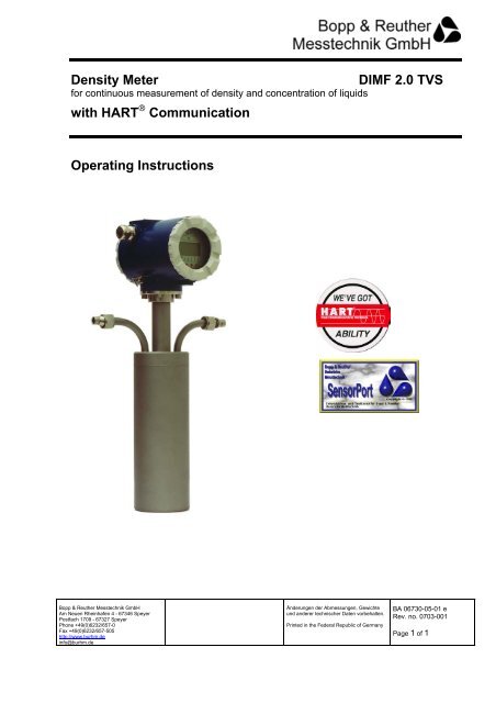
Density Meterfor continuous measurement of density and concentration of liquidswith HART ® CommunicationDIMF 2.0 TVSOperating InstructionsBopp & Reuther Messtechnik GmbHAm Neuen Rheinhafen 4 - 67346 SpeyerPostfach 1709 - 67327 SpeyerPhone +49(0)6232/657-0Fax +49(0)6232/657-505http://www.burhm.deinfo@burhm.deÄnderungen der Abmessungen, Gewichteund anderer technischer Daten vorbehalten.Printed in the Federal Republic of GermanyBA 06730-05-01 eRev. no. 0703-001Page 1 of 1
- Page 2 and 3: TABLE OF CONTENTSForeword 41 Techni
- Page 4 and 5: ForewordI. Transport, delievery, st
- Page 6 and 7: 1.2 Evaluation electronics of trans
- Page 8 and 9: 2 Intended useThe density transduce
- Page 11 and 12: 5.2 Piping- Inner diameter of conne
- Page 13 and 14: 6.2 Additional requirements in haza
- Page 15 and 16: 10.1.1 Process variableMeasured val
- Page 17 and 18: 10.1.4 Output signalUpper rangevalu
- Page 19 and 20: 10.2.5 Programming modeDepending on
- Page 21 and 22: 10.3 Channel overview/ channel assi
- Page 23 and 24: 11 Calculation methods11.1 Calculat
- Page 25 and 26: 12 MaintenanceTwo measures are reco
- Page 27 and 28: 13.2 Errors/defects caused by the t
- Page 29 and 30: 14 Self-monitoring functions14.1 Mo
- Page 31 and 32: 16.2 Application examples for safe
- Page 33: 16.4 Example of configuration logPa
<strong>Density</strong> <strong>Meter</strong>for continuous measurement of density and concentration of liquids<strong>with</strong> <strong>HART</strong> ® <strong>Communication</strong><strong>DIMF</strong> <strong>2.0</strong> <strong>TVS</strong><strong>Operating</strong> InstructionsBopp & Reuther Messtechnik GmbHAm Neuen Rheinhafen 4 - 67346 SpeyerPostfach 1709 - 67327 SpeyerPhone +49(0)6232/657-0Fax +49(0)6232/657-505http://www.burhm.deinfo@burhm.deÄnderungen der Abmessungen, Gewichteund anderer technischer Daten vorbehalten.Printed in the Federal Republic of GermanyBA 06730-05-01 eRev. no. 0703-001Page 1 of 1
TABLE OF CONTENTSForeword 41 Technical data 51.1 <strong>Density</strong> transducer type <strong>DIMF</strong> <strong>2.0</strong> 51.2 Evaluation electronics of transmitter type TR 61.3 Required differential pressure 72 Intended use 83 Measuring principle 84 Installation examples 84.1 By-pass installation 84.1.1 Standard configuration 84.1.2 <strong>with</strong> sampling 94.1.3 <strong>with</strong> sampling and sight glass 94.1.4 <strong>with</strong> sampling and calibration or flushing connection 94.2 Installation into the product line 104.3 Examples for installation positions 105 Mounting 105.1 <strong>Density</strong> transducer 105.2 Piping 115.3 Process connections 115.4 Relationship between permissible ambient temperature and temperature of liquid 116 Electrical connection 126.1 Power supply voltage 126.2 Additional requirements in hazardous area for intrinsically safe operation 137 Commissioning 138 Factory setting 139 On-site adjustment 1410 Configuration, operation 1410.1 Operation via <strong>HART</strong> ® communication 1410.1.1 Process variable 1510.1.2 Diagnosis 1510.1.3 Basic settings 1610.1.4 Output signal 1710.1.5 Special settings 1710.2 Operation <strong>with</strong> the keys (configuration via the control unit) 1710.2.1 Display 1710.2.2 Keys 1810.2.3 Access level 1810.2.4 <strong>Operating</strong> mode 1810.2.5 Programming mode 19We reserve all rights of ownership and exploitation in respect of thesedocuments, including industrial property rights. These documents may onlybe used <strong>with</strong> our express consent in writing, and only to the extent permittedin any such consent. The documents may not be duplicated or madeavailable to third parties. In case of violation of the aforementionedprovisions, we reserve all rights.2
10.2.6 <strong>Operating</strong> mode 1910.2.7 Short description of the control unit 2010.3 Kanalübersicht / Kanalbelegung 2111 Calculation methods 2311.1 Calculation of the operating density (meter calibration) 2311.2 Calculation of the reference density (temperature compensation) 2311.3 Calculation of the concentration through polynom approximation 2311.4 Determination of the hydrometer degrees 2411.5 Mesh point interpolation 2412 Maintenance 2513 Error detection/troubleshooting 2513.1 Errors/defects caused by the liquid 2613.2 Errors/defects caused by the transmitter 2713.2.1 Error code table 2813.3 Errors/defects caused by the density transducer 2814 Self-monitoring functions 2914.1 Monitoring supply voltage 2914.2 Error message 2915 Service 2916 Appendix 3016.1 Wiring diagram 3016.2 Application examples for safe areas 3116.3 Application examples for hazardous areas 3216.4 Example of configuration log 3316.5 EC prototype test certificate 33We reserve all rights of ownership and exploitation in respect of thesedocuments, including industrial property rights. These documents may onlybe used <strong>with</strong> our express consent in writing, and only to the extent permittedin any such consent. The documents may not be duplicated or madeavailable to third parties. In case of violation of the aforementionedprovisions, we reserve all rights.3
ForewordI. Transport, delievery, storageStorage and transport:Protect the devices against humidity, soiling, impact, and damage.Inspection of the delivery:Upon receipt, check the delivery for completeness. Compare the data of the device <strong>with</strong> the data on thedelivery note and in the order records.Report any transport damage immediately after delivery. Damage reported later cannot be recognized.II. WarrantyFor the scope and period of warranty, please refer to the contractual terms of delievery. Claims underwarranty shall be conditional to expert installation and startup in compliance <strong>with</strong> the operatinginstructions for the device.The electronics contains electrostatically sensitive parts. Therefore, electrostatic discharges must beavoided when the electronics housing is open.III. General safety informationRead and observe these <strong>Operating</strong> Instructions thoroughly and keep themavailable for reference.!Installation must be carried out by qualified personnel.For the installation and operation of the device, the regulations of ElexV, thegenerally recognized rules of engineering practice and the <strong>Operating</strong>Instructions must be observed.We do not assume liability for the improper handling, use, installation,operation, or maintenance of the device.In the case of corrosive media, resistance of the oscillating tube must bechecked.Damaged devices must be shut down.We reserve all rights of ownership and exploitation in respect of thesedocuments, including industrial property rights. These documents may onlybe used <strong>with</strong> our express consent in writing, and only to the extent permittedin any such consent. The documents may not be duplicated or madeavailable to third parties. In case of violation of the aforementionedprovisions, we reserve all rights.4
1 Technical data1.1 <strong>Density</strong> transducer type <strong>DIMF</strong> <strong>2.0</strong><strong>Density</strong> range0 to 5000 kg/m³Calibration range 400 to 2000 kg/m³ (Standard)see Configuration Data Sheet suppliedAccuracy better than ±0.02 % (±0.2 kg/m³) (Standard)(under reference condition)see Configuration Data Sheet suppliedRepeatabilitybetter than ± 0.005 % (± 0.05 kg/m³)Temperature range of liquid - 40°C to + 150°C (Standard)see Configuration Data Sheet suppliedTemperature influence <strong>with</strong>outcompensationTemperature compensationPressure influenceapprox. 2,8 kg/m³/°Cvia integral Pt1000in acc. <strong>with</strong> DIN Class Adirectly in the transmitterless than 0.02 kg/m³/bar<strong>Operating</strong> pressure 100 bar (Standard)see Configuration Data Sheet suppliedLiquidpumpable liquidssee Configuration Data Sheet suppliedMaterial: wetted parts 1.4571 (Standard)see Configuration Data Sheet suppliedMaterial: transmitter housing made of 1.4571Smallest inside diameterSpecialtiesWeightProcess connections∅ 10 mmGasket-free constructionon request. Material certificatesin acc. <strong>with</strong> DIN ISO10204-3.1B;see Configuration Data Sheet suppliedapprox. 4.2 kgSwagelok fittings forouter pipe diameter 12 mmsee Configuration Data Sheet supplied(Standard)All percentages are referenced to a density of 1000 kg/m³.For the exact specification of the device version, see the Configuration Data Sheet of the devicesupplied.We reserve all rights of ownership and exploitation in respect of thesedocuments, including industrial property rights. These documents may onlybe used <strong>with</strong> our express consent in writing, and only to the extent permittedin any such consent. The documents may not be duplicated or madeavailable to third parties. In case of violation of the aforementionedprovisions, we reserve all rights.5
1.2 Evaluation electronics of transmitter type TRFunctionsDisplay parametersProgrammable parameters<strong>HART</strong> ® protocolOutput signalPower supplyConnectionCable specificationAmbient temperatureStorage temperatureSafety classesExcites the oscillating element of the density transducer toits natural frequency.Equipped <strong>with</strong> a two-line display and four keys for displayingdata and configuring the on-site transmitter.<strong>HART</strong> ® communicationWhen the process data are changed, the user can perform asimple modification of the set parameters.<strong>Density</strong>, concentration, operating temperature, etc.Lower range and upper range value of the output signal(smallest measuring span approx. 5 kg/m³)Calibration constants, constants of liquid, referencetemperature, etc.Operation using a PC or laptop equipped <strong>with</strong> theSensorPort 2 configuration software together <strong>with</strong> the <strong>HART</strong> ®interface or operation using a <strong>HART</strong> ® hand-held terminal2.3 HC-275 of Rosemount4-20 mA, linearized and temperature-corrected,can be assigned to any display parameter(e.g. operating density, reference density, concentration, °Brix,°Plato or other magnitudes derived from density)24 V DC (min. 14 V DC / max. 30 V DC)2-wire technique via screw terminals;cable enters via cable gland <strong>with</strong> M 20 x 1.5or ½“ NPT thread for pipe installation (conduit system)2 wires, twisted and shielded-10°C to +58°C- 40°C to +70°C on request-40°C to +70°CExi (standard version):EEx ia IIC T4 ZELM 99 ATEX 0008 XDevice group IICategory 1/2 GMeasuring tube designed for Zone 0Exi (Tantalum version):EEx ia IIC T4 ZELM 99 ATEX 0008 XDevice group IICategory 2 GExd:see individual approval94/9/EG, FM, CSA in preparationDegree of protection (housing) IP 65Dimensions (housing)ø100 (D) x 155 (L) x 120 (H) mmMaterial (housing)Cast aluminumWeight1.2 kgCalibration and configurationAccording to customer data atBopp & Reuther Messtechnik GmbH factoryWe reserve all rights of ownership and exploitation in respect of thesedocuments, including industrial property rights. These documents may onlybe used <strong>with</strong> our express consent in writing, and only to the extent permittedin any such consent. The documents may not be duplicated or madeavailable to third parties. In case of violation of the aforementionedprovisions, we reserve all rights.6
1.3 Required differential pressure<strong>Density</strong> transducers of the <strong>DIMF</strong> series measure independently of flow rate and also at flow rate zero.Their application is therefore normally problem-free. Care must, however, be taken to ensure that theoperating flow rate in the transducer- updates the sample fast enough- equalizes the temperature in the tranducer- avoids air or gas bubbles ordeposits in the oscillating tube- does not cause cavitation in the oscillating tube- does not cause wear through abrasivesRecommended operating flow rate through the density transducer:<strong>DIMF</strong> <strong>2.0</strong>: approx. <strong>2.0</strong> l/minPressure loss diagramPressure loss∆P [bar](H 2 O; 20°C)101<strong>DIMF</strong><strong>2.0</strong>0.10.010.0010.1 1 10 100Flow rate [l/min]<strong>DIMF</strong><strong>2.0</strong>0 1.5 6 50 l/min2 l/minPermissible flow ratesRecommended flow0.1 110 1000.01 0.11 10l/minm³/hWe reserve all rights of ownership and exploitation in respect of thesedocuments, including industrial property rights. These documents may onlybe used <strong>with</strong> our express consent in writing, and only to the extent permittedin any such consent. The documents may not be duplicated or madeavailable to third parties. In case of violation of the aforementionedprovisions, we reserve all rights.7
2 Intended useThe density transducer type <strong>DIMF</strong> allows the continuous measurement of the density of liquids and liquidmixtures. The proven oscillating element principle ensures great accuracy in combination <strong>with</strong>outstanding long-term stability. The easy-to-get-on-<strong>with</strong>-construction assures reliable operation, evenunder tough process conditions.3 Measuring principleThe real sensor of the density transducer is an oscillating element in the form of a tube bent into a tuningfork. The liquid to be measured passes continuously through this element. Excited electromagnetically byan excitation coil, it will oscillate at its natural frequency. Changes in the density of the liquid lead tochanges in the natural frequency. This change in frequency, sensed by a pick-up coil, represents themeasurement effect. An additional built-in resistance thermometer measures the process temperature,which can also be used to equalize the temperature influence in the transducer.Each density transducer is calibrated <strong>with</strong> different liquids of different densities. The transducer constantsfor the calculation of the density from the frequency, the calibration temperature and the correctioncoefficients for temperature influence are given under section 16.4 Example of configuration log.4 Installation examplesIn principle, the density transducer can be installed directly into the product line (for permissible flowrates, see section 1.3). For higher flow rates or measurements at containers, installation in a by-pass isrecommended.4.1 By-pass installation4.1.1 Standard configurationPartShut-off valve ø12Straight tube fittingQty.22We reserve all rights of ownership and exploitation in respect of thesedocuments, including industrial property rights. These documents may onlybe used <strong>with</strong> our express consent in writing, and only to the extent permittedin any such consent. The documents may not be duplicated or madeavailable to third parties. In case of violation of the aforementionedprovisions, we reserve all rights.8
4.1.2 <strong>with</strong> samplingPartShut-off valve ø12Straight tube fitting ø12T-type connector ø12Screw cap ø12Qty.32114.1.3 <strong>with</strong> sampling and sight glassPartSight glass R3/8“Shut-off valve ø12Straight tube fitting ø12Male connector R3/8“- ø12T-type connector ø12Screw cap ø12Qty.1322114.1.4 <strong>with</strong> sampling and calibration or flushing connectionPartShut-off valve ø12Straight tube fitting ø12T-type connector ø12Screw cap ø12Qty.4222We reserve all rights of ownership and exploitation in respect of thesedocuments, including industrial property rights. These documents may onlybe used <strong>with</strong> our express consent in writing, and only to the extent permittedin any such consent. The documents may not be duplicated or madeavailable to third parties. In case of violation of the aforementionedprovisions, we reserve all rights.9
5.2 Piping- Inner diameter of connecting pipe: min. ø10- Sampling connection to be fitted laterally when product line is in horizontal position.- By-pass pipes should be as short as possible.- If necessary, provide both heat insulation and flushing connections (the latter close to thedensity transducer).5.3 Process connectionsEnsure that the density transducer connection is compatible <strong>with</strong> the by-pass connections.For the connection type of your density transducer, see the Configuration Data Sheet supplied.5.4 Relationship between permissible ambient temperature and temperature of liquid<strong>DIMF</strong> ... (interconnected version)ClassAmbienttemperatureTemperature ofliquidTypeT2T3T3464649210200170HHigh temperatureT3T4T4T45052545815013511060S+HStandard temperatureand high temperatureWe reserve all rights of ownership and exploitation in respect of thesedocuments, including industrial property rights. These documents may onlybe used <strong>with</strong> our express consent in writing, and only to the extent permittedin any such consent. The documents may not be duplicated or madeavailable to third parties. In case of violation of the aforementionedprovisions, we reserve all rights.11
6 Electrical connection6.1 Power supply voltage- The transmitter type TR must be supplied <strong>with</strong> 24 V DC, 2-wire technique.- Terminal voltage 14 to 30 V DC (terminals 1 and 2)- Recommendation: 2-wire cables, twisted and shielded(cable diameter 6-12 mm)- Ground cable shield according to section 16.1 Wiring diagram.- In order to ensure safe <strong>HART</strong> ® communication, the limits for theminimum load <strong>with</strong> R L ≥ 250 Ω must be observed.- For the maximum amount of line and load resistance, see diagram below.The maximum load depends on the supply voltage.Maximum load1000800Load [ohm]600400200014 16 18 20 22 24 26 28 30Supply voltage [V]ForUB< 15.2V:( UB− 14V)R =0.004AForUB≥ 15.2V:( UB− 8.5V)R =0.022AWe reserve all rights of ownership and exploitation in respect of thesedocuments, including industrial property rights. These documents may onlybe used <strong>with</strong> our express consent in writing, and only to the extent permittedin any such consent. The documents may not be duplicated or madeavailable to third parties. In case of violation of the aforementionedprovisions, we reserve all rights.12
6.2 Additional requirements in hazardous area for intrinsically safe operation- Observe installation requirement in accordance <strong>with</strong> DIN EN 60079-14 / VDE 0165, Part 1.- Connected loads power supply voltageUmax = 30 V Imax = 110 mA Pmax = 825 mWCi ≤ 34 nF Li ≤ 0.6 mH- Power supply must be provided by a certified, intrinsically safe supply unit or bysafety barriers.- In order to connect the bonding conductor safely, use theinternal and external bonding connector terminals, which have been designedfor a wire range of 1.5 mm² (inside) or 4 mm² (outside).- If barriers are part of the supply circuit, they must also be connected to the commonbonding conductor.7 Commissioning- Flush product lines before connecting the density transducer- Ensure that all connections are tight- Deaerate density transducer- Switch on power supply8 Factory settingThe density transducer <strong>DIMF</strong> <strong>2.0</strong> TR has been parameterized according to customer specifications. Afterswitching on the power supply, the specified parameters (e.g. density, reference density or concentration)and the operating temperature will be shown on the display.If these parameters have changed since the order was placed, the setting can be modified (seesection 10 Configuration, operation).We reserve all rights of ownership and exploitation in respect of thesedocuments, including industrial property rights. These documents may onlybe used <strong>with</strong> our express consent in writing, and only to the extent permittedin any such consent. The documents may not be duplicated or madeavailable to third parties. In case of violation of the aforementionedprovisions, we reserve all rights.13
9 On-site adjustmentAn on-site adjustment is carried out if an error has been detected due to certain changes in on-siteconditions, after the reasons according to section 13.1 have been checked. By changing the transducerconstant K 0 , a simple adjustment can be performed.Example:Measurement condition Temperature must be relatively stableRho (measured density) = 996.6 Kg/m³Rho (setpoint value) = 996.0 Kg/m³ (e.g. value stated in table)difference (misalignment) = +0.6 Kg/m³current K 0 value = -7360.708 Kg/m³setpoint K 0 valuecorrect K 0 value= K 0 (current) – misalignment= - 7360.708 Kg/m³ - 0.6 Kg/m³= -7361.308 Kg/m³Now this value must be entered into the transmitter type TR.If possible, the constants K 1 and K 2 should not be modified by the user.10 Configuration, operationThe transmitter can be configured (operated) in two different ways:1. <strong>HART</strong> ® communication2. On-site operation <strong>with</strong> keys and display10.1 Operation via <strong>HART</strong> ® communicationThe device can be operated using a PC or laptop and the SensorPort 2 configuration software inconnection <strong>with</strong> a <strong>HART</strong> ® interface.A <strong>HART</strong> ® Communicator is another operating element which can be used (e.g. model HC-275 ofRosemount). The operating functions of the HC-275 are defined in the <strong>HART</strong> "Device DescriptionLanguage" (DDL). Using the HC-275 the <strong>DIMF</strong> can be operated or configured on site. For the electricalconnection, see section 16.1.We reserve all rights of ownership and exploitation in respect of thesedocuments, including industrial property rights. These documents may onlybe used <strong>with</strong> our express consent in writing, and only to the extent permittedin any such consent. The documents may not be duplicated or madeavailable to third parties. In case of violation of the aforementionedprovisions, we reserve all rights.14
10.1.1 Process variableMeasured value: The current measured value is displayed. The measured value can be selectedfrom a list <strong>with</strong> density or concentration operating modes.The units are defined in this list. The measured value is firmly assigned to the<strong>HART</strong> ® primary variable and thus also to the current output.<strong>Operating</strong> density,reference density,frequency, temperature: The uncorrected or the temperature-corrected operating density, the referencedensity, the oscillation frequency and the medium temperature can also bedisplayed in the concentration operating mode and transmitted via <strong>HART</strong> ®variables 2 to 4. The assignment is free.Output range %: Display of the actual measured value in %Output current: The setpoint value of the present current output is displayed in mA.10.1.2 Diagnosis<strong>Communication</strong> statusDevice address: The device address for polling operation can be assigned a value between 1and 15. Address = 0 means analog operation, address > 0 means pollingoperation. If the <strong>DIMF</strong> is to be installed in a multidrop system,the address must be between 1 and 15. For this, the <strong>DIMF</strong> must firstbe configured <strong>with</strong> the desired address in a point-to-point connection.Number of preambles:The read value indicates how many preambles the master has to send to theslave in its inquiry. The written value indicates how many preamblesthe <strong>DIMF</strong> has to send to the master.Device statusConfiguration changed: If the configuration is changed during operation, the "configurationchanged" flag will be set and displayed.Reset "configurationchanged" flag: The "configuration changed" flag can be removed.Error codes:The error codes of the <strong>DIMF</strong> are displayed. The most recent erroris displayed. All previous error messages are no longeravailable.Limiting valuesTemperatures:The <strong>DIMF</strong> measures the product temperature and the temperature in theelectronics housing. The min. and max. limiting values are stored anddisplayed.We reserve all rights of ownership and exploitation in respect of thesedocuments, including industrial property rights. These documents may onlybe used <strong>with</strong> our express consent in writing, and only to the extent permittedin any such consent. The documents may not be duplicated or madeavailable to third parties. In case of violation of the aforementionedprovisions, we reserve all rights.15
10.1.3 Basic settingsDevice informationModel code:The model code of the device is displayed.Device identification: The serial number of the electronics is displayed.Device type:The device type is displayed.Sensor type: Defaults to 0.Manufacturer code: The manufacturer's name is displayed.Distributor code: The distributor's name is displayed.TAG:The TAG address (measuring point number) is displayed.Date:The date of the most recent configuration change will be displayed.(must be overwritten manually).Descriptor:A short text of 16 characters can be entered by the user or beread.Message:A short text of 32 characters can be entered by the user or beread.Write protection: The <strong>DIMF</strong> does not support write protection.Manufacturing no. sensor: The manufacturing number of the sensor can be read.Manufacturing no. device: The manufacturing number of the device can be read. It is identical <strong>with</strong>the sensor manufacturing number.Revision levels, universal,standard, software,hardware:The revision numbers are read.Tranducer dataTransducer factors:The factors K 0 , K 1 , K 2 , K T0 , K T1 , K T2 and T kal can be read and changed.Medium dataMedium factors:The factors α, K C0 , K C1 , K X0 , K X1 , K X2 and T ref can be read and changed.Process dataDamping:Upper/lowerrange value:Minimum measuringrange span:Damping affects the display and the output current.A value between 0 to 5 can be set. The increment isapprox. 0.25 s.The meter range is factory-set for eachapplication.The measuring range span can be freely defined <strong>with</strong>in the meter range.However, the set values must not be below the minimum measuring spanrange, as this may lead to step changes of the output current.We reserve all rights of ownership and exploitation in respect of thesedocuments, including industrial property rights. These documents may onlybe used <strong>with</strong> our express consent in writing, and only to the extent permittedin any such consent. The documents may not be duplicated or madeavailable to third parties. In case of violation of the aforementionedprovisions, we reserve all rights.16
10.1.4 Output signalUpper rangevalueLower rangevalue:Selection ofmeasured variable:Current simulation:Alarm 21.8 mA:Characteristic value for the 20-mA point.Characteristic value for the 4-mA point.The measured variable has been assigned to the <strong>HART</strong> ® primary variable andthus to the current output. When displaying density, the user can changebetween operating or reference density. When calculating the concentration,the user can select between the two different methods.In order to test the devices connected in series, a fixed outputcurrent of 3.9 to 22 mA can be set. After the test, the current value0 mA must be entered to end simulation.An alarm signal can be transmitted via the current loop.The current then rises to 21.8 mA. This alarm is generated due to amaloperation of the <strong>DIMF</strong>. The alarm function can be switched off.10.1.5 Special settingsElectronic adjustmentCalibrate current output: The characteristic of the analog current output can be calibrated in its zeropoint at 4 mA and in its slope at 20 mA. It must be observed that the zero pointwill be calibrated before the upper range value.Reset device:With this command, the device can be restored to a defined operating statepresent after the supply voltage was applied.10.2 Operation <strong>with</strong> the keys (configuration via the control unit)To access the keys, the screw cover of the longer end of the housing must be opened. When the housingcover has been opened, the degree of protection of the housing is not ensured.After the configuration has been completed, the housing cover must be remounted and the screws mustbe fastened fingertight (be careful not to damage the sealing ring).!For the Exd version the housing may only be removed after it has been ensured thatthere is no explosive atmosphere.The covers of the Exd version are secured against opening. In order to open the cover, the locking barmust be swiveled sideways and clamped in this position. After closing the covers, they must beresecured.10.2.1 DisplayThe transmitter type TR has a two-line display <strong>with</strong> 8 digits for each line. Each line is subdivided into twofields:- in the 1 st field the channel no. is displayed (1 digit)- in the 2 nd field the corresponding measured valuesor the constants are displayed (7 digits).The values displayed in the upper line cannot be changed. The values displayed in the lower line(programming line) can be changed.The activated line is marked <strong>with</strong> a triangle behind the channel number. By pressing the ENTER key, youcan toggle between the lines.We reserve all rights of ownership and exploitation in respect of thesedocuments, including industrial property rights. These documents may onlybe used <strong>with</strong> our express consent in writing, and only to the extent permittedin any such consent. The documents may not be duplicated or madeavailable to third parties. In case of violation of the aforementionedprovisions, we reserve all rights.17
10.2.2 KeysThe transmitter type TR has four operating keys:and- increases or decreases the channel no. in operating mode- increases or decreases the digits in the programming mode↵P- moves to the next input position (the corresponding digit blinks)- accepts the current channel contents whenshifting to the very right and leaving the display- toggles between the lower and the upper line (only in operating mode)- changes from the operating to the programming mode- in programming mode: places the comma next to the entry position (blinking digit)- deletes error message on channel "]"- pressing this key for a couple of seconds resets the entry position (blinking digit)10.2.3 Access levelIn the operating mode, the measured values and constants displayed cannot be changed. When thetransmitter type TR is switched on,- display level (operating mode)all configuration data and measuring values can be displayed- user level (programming mode)additionally the upper and lower range value can be configured, an on-siteadjustment (K 0 and K X0 ) is possible and the value for the current simulation isadjustable- service level (programming mode)all parameters are configurable (see table in section 10.3)10.2.4 <strong>Operating</strong> modeIn the operating mode, the measured values and constants displayed cannot be changed. When thetransmitter type TR is switched on,- a display test is carried out- the operating mode is activated automatically- the current measured variable, density (kg/m³) or concentration (%),depending on the operating mode, is displayed in the upper line- the current temperature (°C) is displayed in the lower line- the upper line is activatedIf a different value is to be displayed in the lower line, the lower line must be activated by pressing "↵".Then you select the corresponding channel no. (see table in section 10.3) by pressing " " or " " . Oncethe last channel number has been reached the display moves back to the first channel. Once the firstchannel number has been reached, the display moves to the highest channel no.We reserve all rights of ownership and exploitation in respect of thesedocuments, including industrial property rights. These documents may onlybe used <strong>with</strong> our express consent in writing, and only to the extent permittedin any such consent. The documents may not be duplicated or madeavailable to third parties. In case of violation of the aforementionedprovisions, we reserve all rights.18
10.2.5 Programming modeDepending on the operating mode, in programming mode, the device parameters and the mediumconstants can be programmed or modified on site. The constants can only be programmed in the lowerline. For this, the "P" key must be actuated until the first digit blinks in the display field. This digit can thenbe changed <strong>with</strong> the keys " " or " ". Pressing the ↵ key moves you to the next entry position(corresponding digit blinks). To place a comma, you press the P key for a short moment. After leaving thelast position, the channel is accepted <strong>with</strong> the current contents. By pressing the P key for approx. 3seconds the current input position can be reset to the previous position.- while programming the K 0 and K X0 values all measured andcalculated values are frozen;the upper display line will not be activated.- if the "programming" function has been initiated but not terminated,it will be terminated automatically after approx. 2 minutes;the old value will be restored.- channel no. "]“ is used for displaying error codes;these can be deleted by pressing the "P" key(see error code table in section 13.2.1).10.2.6 <strong>Operating</strong> modeBy selecting the operating mode (channel E) you define the calculation method according to which themeasured variable is to be acquired and the output signal is to be represented.By selecting the operating mode you define- the assignment of the primary <strong>HART</strong> ® variables (current output signal)- the measured value in "channel 0"- the calculation method (see section 11).The analog output signal (4 to 20 mA) can be freely assigned to the desired measuring range (lowerrange value: channel 5, upper range value: channel 6) <strong>with</strong>in the meter range.The minimum measuring range span should not be below a density range of 5 kg/m³.We reserve all rights of ownership and exploitation in respect of thesedocuments, including industrial property rights. These documents may onlybe used <strong>with</strong> our express consent in writing, and only to the extent permittedin any such consent. The documents may not be duplicated or madeavailable to third parties. In case of violation of the aforementionedprovisions, we reserve all rights.19
10.2.7 Short description of the control unitSelect channel Toggles between the lines ↵ChannelDisplayDigit7 6 5 4 3 2 1 0Programming line?2-line displayDigit blinks in P modeProgramming(activate programminglevelSelect position↵P Accept value ↵Set digitPlace commaPKey<strong>Operating</strong> modeProgramming modePChannel selectionActivateprogramming mode Increase channel no. Decrease channel no.Set decimal pointSet parametersProlonged pressingresets entry position Increase digit Decrease digit↵Toggle between linesProlonged pressing:Display testMove to next digitor accept valueExit programmingmodeWe reserve all rights of ownership and exploitation in respect of thesedocuments, including industrial property rights. These documents may onlybe used <strong>with</strong> our express consent in writing, and only to the extent permittedin any such consent. The documents may not be duplicated or madeavailable to third parties. In case of violation of the aforementionedprovisions, we reserve all rights.20
10.3 Channel overview/ channel assignmentchannel description symbol unit default value level- LCDdisplayed paramtersmeasuringrange0 0 measured valueρ resp. C kg/m³ resp. # - -(density ρ resp. concentration C)1 1 current output I mA - -2 2 oscillating frequency f Hz - -3 3 medium temperature t °C - -4 4 output range (I-4)/16 % - -5 5 lower range value ρ resp. C min 800 16 6 upper range value ρ resp. C max 1200 17 7 constant for density polynom K 0 kg/m³ -12000,00 1meter constants8 8 constant for density polynom K 1 kg/m³•s -190,0000 29 9 constant for density polynom K 2 kg/m³•s² -275,0000 210 A temperature-correction coefficient K T0 kg/m³•K -2,60 211 b temperature-correction coefficient K T1 10 -6 /K -50,00 212 C temperature-correction coefficient K T2 0 213 F calibration temperature t kal °C 20 214 E operating mode switch 0001-01 0system constants15 L current adjustment 4mA - 216 H current adjustment 20mA - 217 I Pt1000 offset - 218 J Pt1000 gradient - 219 n temperature compensation K C0 kg/m³•K 0,5 2medium constants20 o temperature compensation K C1 1/K 0 221 P temperature compensation K C2 kg/m³•K² 0 222 q constant for polynom approximation K X0 # 123 r constant for polynom approximation K X1 # / kg/m³ 224 U constant for polynom approximation K X2 #•10 -5 / (kg/m³)² 2servicevalues25 d reference temperature t Bez °C 15 126 t current simulation I mA 000 127 y service value (allocation see channel E) ρ kg/m³ - -28 ] status information error code 00 -#: unit according the requested application (for example: mass-%, Brix ...)We reserve all rights of ownership and exploitation in respect of thesedocuments, including industrial property rights. These documents may onlybe used <strong>with</strong> our express consent in writing, and only to the extent permittedin any such consent. The documents may not be duplicated or madeavailable to third parties. In case of violation of the aforementionedprovisions, we reserve all rights.21
<strong>Operating</strong> mode switch channel EDisplay lower line7 6 5 4 3 2 1 0E► - - -Access level012display level (operating mode )user level (programming mode)service level (programming mode)Service value (channel y)012operating density (not corrected)operating density (temperature corrected)reference density (operating mode 01)<strong>Operating</strong> mode00operating density in kg/m³01reference density in kg/m³02volume concentration in %- polynom approximation03volume concentration in %- mesh point interpolation30concentration mass/volume- polynom approximation31concentration mass/volume- mesh point interpolation32mass concentration in %- polynom approximation33mass concentration in %- mesh point interpolation04operating density in kg/m³- mesh point interpolation1212121226600112233456Brix - Fischer ρ < 1g/cm³ (lighter than water)ρ > 1g/cm³ (heavier than water)Baumé rationell ρ < 1g/cm³ (lighter than water)ρ > 1g/cm³ (heavier than water)Baumé (american) ρ < 1g/cm³ (lighter than water)ρ > 1g/cm³ (heavier than water)Balling ρ < 1g/cm³ (lighter than water)ρ > 1g/cm³ (heavier than water)Twaddle ρ > 1g/cm³ (heavier than water)API (linear)S. G. (specific gravity 60/60)We reserve all rights of ownership and exploitation in respect of thesedocuments, including industrial property rights. These documents may onlybe used <strong>with</strong> our express consent in writing, and only to the extent permittedin any such consent. The documents may not be duplicated or madeavailable to third parties. In case of violation of the aforementionedprovisions, we reserve all rights.22
11 Calculation methods11.1 Calculation of the operating density (meter calibration)density polynomρ B = K 0 + K 1 • τ + K 2 • τ 2equation 1ρ Boperating density not corrected [kg/m³]K 0 , K 1 , K 2meter constants from calibrationτ = 10000/Frequenz period [s -1 ]temperature corrected operating densityρ BT = ρ B + (K T0 + K T1 • 10 -6 • ρ B ) • (t - t Kal ) + K T2 • (t - t Kal )²equation 2aρ BTρ Btt KalK T0 , K T1 , K T2operating density temperature corrected [kg/m³]operating density not corrected [kg/m³]operating temperature [°C]calibration temperature [°C]meter constants from calibrationtemperature corrected operating density for standard calibration (K T2 =0)ρ BT = ρ B + (K T0 + K T1 • 10 -6 • ρ B ) • (t - t Kal )equation 2b11.2 Calculation of the reference density (temperature compensation)conversion of the operating density into reference temperatureρ Bez = ρ BT + (K C0 + K C1 • ρ BT ) • (t - t Bez ) + K C2 • (t – t Bez )²equation 3aρ Bezρ BTtt BezK C0 , K C1 , K C2reference density [kg/m³]operating density temperature corrected [kg/m³]operating temperature [°C]reference temperature[°C]meter constants for temperature compensation<strong>with</strong> simplified calculation method (K C1 = K C2 =0)ρ Bez = ρ BT + K C0 • (t - t Bez )equation 3bK C0 :temperature factor [kg/m³•K]11.3 Calculation of the concentration through polynom approximationconversion of the reference density into concentrationC = K X0 + K X1 • ρ Bez + K X2 • 10 -5 • ρ Bez ²equation 4C concentration at reference temperature (#)ρ Bezreference density [kg/m³]K X0 , K X1 , K X2medium constant for concentration# concentration unit according the requested application(for example masse-%, Brix ...)We reserve all rights of ownership and exploitation in respect of thesedocuments, including industrial property rights. These documents may onlybe used <strong>with</strong> our express consent in writing, and only to the extent permittedin any such consent. The documents may not be duplicated or madeavailable to third parties. In case of violation of the aforementionedprovisions, we reserve all rights.23
11.4 Determination of the hydrometer degreesFor the determination of hydrometer degrees the computation of the reference density is made byequation 3. The reference temperature is for this firmly given. The equations for the conversion of thehydrometer scales, as well as the respective reference temperature are arranged in the following table:hydrometer degreereference temp.t in °Cliquidsheavier than waterliquidslighter than waterBrix-Fischer15,625(12,3°R)400400400 − − 400ddBaumé (rationell) 15144,30 144,30144,30− − 144, 30ddBaumé (american)15,56(60°F)145140145 − − 130ddBalling 17,5Twaddle15,56(60°F)200200200 − − 200dd200(d− 1)-API (linear)S.G. (specific gravity 60/60)d: density ratiod t / tρt=ρwater,t15,56(60°F)15,56(60°F)141,5- − 131, 5dρρ60°Fwater,60°FThe calculation method determinate the choice of the operating mode (see table “<strong>Operating</strong> mode switchchannel E” section 10.3).11.5 Mesh point interpolationWith this calculation method the reference density resp. the concentration becomes over a mesh pointinterpolation from the measured operating density (equations section 11.1) determined. For this theconnection is given e.g. between concentration, density and temperature c=f(ρ•t) in tabular form. Thetable may contain maximally 400 mesh points, <strong>with</strong> maximally 80 lines or 80 columns. The materialvalues must be present as Excel table in the following form:ρttemperaturee.g. concentration tabledensityconcentrationc(max. 400 mesh points*)* e.g. 80 density values at 5 temperaturesThe calculation of the concentration takes place via linear interpolation. The unit results from the giventable codes. The mesh point tables from available material values and the transfer of the mesh pointvalues to the meter take place <strong>with</strong> SensorPort via program "<strong>DIMF</strong> table" (see for this operatinginstruction to the program "<strong>DIMF</strong> table").We reserve all rights of ownership and exploitation in respect of thesedocuments, including industrial property rights. These documents may onlybe used <strong>with</strong> our express consent in writing, and only to the extent permittedin any such consent. The documents may not be duplicated or madeavailable to third parties. In case of violation of the aforementionedprovisions, we reserve all rights.24
12 MaintenanceTwo measures are recommended: cleaning and zero point adjustment.CleaningThe density transducer should be cleaned when, for example, liquids tending to sedimentation aremeasured. The easiest method is to increase the flow velocity through the density transducer to themaximum permissible value for some minutes to flush away sediments and solids. If this measure doesnot prove successful, the density transducer should be cleaned <strong>with</strong> a special detergent if flushingconnections are provided. In this case the corrosion resistance of the wetted parts of the densitytransducer must be observed.Zero point adjustmentAbrasion, sedimentation or corrosion may shift the zero point of the density transducer. The zero pointshift can be established by a comparison measurement and rectified by an on-site adjustment (seesections 9 and 13.1).13 Error detection/troubleshootingPeriodical checks of the density transducer facilitate error detection and may provide information aboutpossible error sources.These checks can normally be limited to a comparison between the measured value and a referencemeasurement, using either lab equipment or a density transducer as a master.For this purpose it is essential that the test equipment is of sufficient reliability and accuracy (e.g. testequipment approved by the Weights and Measurement Authorities) to ensure correct results. During thetest, the conditions must be comparable to the actual operating conditions; if necessary, the temperaturecoefficient of the liquid must be taken into consideration.If the measured value does not match the result of the reference measurement, the following measuresshould be taken:- Check the evaluation electronis (transmitter):electrical connection, power supply, cabling to the transducer.- Ensure that the data of the calibration log or theservice list and the programmed parameters of the evaluation electronics are identical.- Inspect the density transducer for damage(temper colors on the transducer housing caused by high temperature and othermechanical defects such as damaged transmitter housing, damaged gaskets or terminals).- Look for disturbances from process side (e.g. empty product lines or gas bubbles).A seriously damaged density transducer should be dismounted and returned to the service department ofBopp & Reuther Messtechnik (see section 15).Otherwise, additional inspections should be performed. In general, there are three types of error sources:- errors/defects caused by the liquid- errors/defects caused by the transmitter- errors/defects caused by the density transducerWe reserve all rights of ownership and exploitation in respect of thesedocuments, including industrial property rights. These documents may onlybe used <strong>with</strong> our express consent in writing, and only to the extent permittedin any such consent. The documents may not be duplicated or madeavailable to third parties. In case of violation of the aforementionedprovisions, we reserve all rights.25
13.1 Errors/defects caused by the liquidSymptom Possible reason RemedyNegative measuring errorUnstable indicationPositive measuring errorLong-term driftNegative measuring errorLong-term driftIndication does not change oris moving too slowGas or air bubbles in theliquid or inside the densitytransducerDeposits inside thetransducerCorrosionAbrasionFlow velocity too low or zeroIncrease pressure in product lineDeaerate product lineIncrease flow velocity in the transducerIncrease flow velocity to approx.5 m/sec., for exampleFlush away sediments inside thedensity transducer <strong>with</strong> detergent(ensure that wetted parts are corrosionresistant)Clean transducer pipe various times<strong>with</strong> a sphere and by applying theappropriate pressureCheck material resistance of thedensity transducerReduce flow velocity in the transducer(recommende value < 1 m/s)Open all shut-off valvesIncrease flow velocity in the transducerDefects caused by sedimentation, corrosion or abrasion can often be seen after the density transducerhas been dismounted.If necessary, the density transducer should be returned to the service department of Bopp & ReutherMesstechnik for recalibration or an on-site adjustment (see section 9) should be performed using theoffset value K 0 .We reserve all rights of ownership and exploitation in respect of thesedocuments, including industrial property rights. These documents may onlybe used <strong>with</strong> our express consent in writing, and only to the extent permittedin any such consent. The documents may not be duplicated or madeavailable to third parties. In case of violation of the aforementionedprovisions, we reserve all rights.26
13.2 Errors/defects caused by the transmitterSymptom Possible reason RemedyCurrent output does not reactor reacts incorrectlyCurrent output is unsteadyDisplay blinks constantlyEmpty displayChannel ] shows errornumberWrong density orconcentration is displayed ortemperature is "not"compensatedNo frequency signal orsenseless frequency betweentest terminals on displayboardDisplayed temperature iswrongPower supply voltage too lowCable resistance too highTransmitter is defectiveUpper range value has beenreachedShield not grounded orbonding conductor notconnectedPower supply voltage too lowPower supply voltage too lowTransmitter is defectiveWrong parameterization (e.g.wrong unit for temperaturecoefficient alpha)Specified measuring rangehas been exceededAir or gas bubble in the liquidTransmitter is incorrectlyconnected to transducerDefective transducerTransmitter is defectiveTransmitter is incorrectlyconnected to transducerDefective transducerCheck power supply voltage(> 14 V DC, < 30 V DC)Larger cable cross sectionCheck current output(see section 14 Self-monitoringfunctions)Replace transmitter if necessaryExpand measuring range (channels 5and 6)Ground cable shield or connect bondingconductor in cable glandSupply voltage must be > 14 V DC atthe terminalCheck supply voltageReplace transmittersee error code table, section 13.2.1Check the programmed log data andtheir signs (equations in section 11might be helpful)Requires new programming datasee section 13.1 Errors/defects causedby the liquidCheck sensor connectionsCheck transducer coils if necessary(see section 13.3)Replace transmitterCheck Pt1000 connectionsCheck temperature sensor (see section13.3)We reserve all rights of ownership and exploitation in respect of thesedocuments, including industrial property rights. These documents may onlybe used <strong>with</strong> our express consent in writing, and only to the extent permittedin any such consent. The documents may not be duplicated or madeavailable to third parties. In case of violation of the aforementionedprovisions, we reserve all rights.27
13.2.1 Error code tableNo. Description Remedy0 No error occurred1Watchdog reset or interruption of powersupply2 P1000 line short-circuited3 P1000 line interruptedCheck power supply voltageResolve short-circuit, return device to Bopp &Reuther Messtechnik, if necessaryRe-establish connection, return device toBopp & Reuther Messtechnik, if necessary33 Error in <strong>HART</strong> ® protocol Contact Bopp & Reuther Messtechnik42 Data error in the A/D converter Contact Bopp & Reuther Messtechnik75Device temperature exceeds quartzcalibration intervalControl device environmentAll error messages can be deleted by pressing the "P" key when the programming line is activated inchannel "]". If the error number re-appears on the display, the error source has not been resolved.13.3 Errors/defects caused by the density transducerDisconnect the device, open the screw-down cover, loosen the two fastening screws of the electronicsand carefully remove the electronics. For the version <strong>with</strong> control unit, the digital display must be screwedoff first. Disconnect all coil and temperature sensor cables from the transducer in order to check theresistances in accordance <strong>with</strong> the following data:- Resistance of the transducer coil at 20°C between blue (BU) and yellow (YE) 60 Ω- Resistance of the excitation coil at 20°C between black (BK) and white (WH) 125 Ω- Resistance against mass > 100 MΩThe wires of the temperature transducer are marked <strong>with</strong> a black shrinkdown sleeve.Resistance levels PT1000 between blue (BU) and yellow (YE)Temperature (°C) -20 0 20 40 60 80 100 120 140Resistance (Ω) 922 1000 1078 1155 1232 1309 1385 1460 1536Symptom Possible reason RemedyCoil resistance is zero orinfiniteResistance of Pt1000 is zeroor infiniteShort circuit between cableand housingCoil is defectivePt1000 is defectiveFrame connectionReturn density <strong>with</strong> transmitter to Bopp& Reuther MesstechnikReturn density <strong>with</strong> transmitter to Bopp& Reuther MesstechnikReturn density <strong>with</strong> transmitter to Bopp& Reuther MesstechnikWe reserve all rights of ownership and exploitation in respect of thesedocuments, including industrial property rights. These documents may onlybe used <strong>with</strong> our express consent in writing, and only to the extent permittedin any such consent. The documents may not be duplicated or madeavailable to third parties. In case of violation of the aforementionedprovisions, we reserve all rights.28
14 Self-monitoring functions14.1 Monitoring supply voltageAfter a power failure a power-ON reset will be carried out, and the error code 1 will be displayed inchannel "[" or the error will be reported via <strong>HART</strong> ® .14.2 Error messageAn error code will be displayed on channel "]". The error that was reported last will be displayed.For the corresponding error description, see section 13.2.1 Error code table.15 ServiceBopp & ReutherMesstechik GmbHService Abt. MRV-SAm Neuen Rheinhafen 467346 SpeyerPhone: +49 (0) 6232 657-403Fax: +49 (0) 6232 657-401We reserve all rights of ownership and exploitation in respect of thesedocuments, including industrial property rights. These documents may onlybe used <strong>with</strong> our express consent in writing, and only to the extent permittedin any such consent. The documents may not be duplicated or madeavailable to third parties. In case of violation of the aforementionedprovisions, we reserve all rights.29
16 Appendix16.1 Wiring diagram<strong>DIMF</strong> densitytransducermeasurement of density and4 to 20mAR Lmin250ςTransmitterpower supplyunit<strong>HART</strong> 15 to 30VTP1 2 3 1- + 2 3 - +4Not used<strong>HART</strong>InterfaceSensorPortTestcircuit[V]<strong>HART</strong> CommunicatorGrounding the cableshieldDetail ABraided shieldA2-wire cable, twistedFor max. line resistance,see diagram section 6.1We reserve all rights of ownership and exploitation in respect of thesedocuments, including industrial property rights. These documents may onlybe used <strong>with</strong> our express consent in writing, and only to the extent permittedin any such consent. The documents may not be duplicated or madeavailable to third parties. In case of violation of the aforementionedprovisions, we reserve all rights.30
16.2 Application examples for safe areasLocal indication <strong>with</strong>out signal transmission<strong>DIMF</strong>Pulse4-20mA4 +3 -2 +1 -+24V-External groundterminalGround shield incable glandAnalog transmission 4 to 20mA to indicator or recorder<strong>DIMF</strong>Pulse4-20mA4 +3 -2 +1 -Indicator0 0 0 +24V-External groundterminalGround shield incable glandAnalog transmission 1 to 5V to indicator or recorder<strong>DIMF</strong>Pulse4-20mA4 +3 -2 +1 -Indicator0 0 0250ς+24V-External groundterminalGround shield incable glandWe reserve all rights of ownership and exploitation in respect of thesedocuments, including industrial property rights. These documents may onlybe used <strong>with</strong> our express consent in writing, and only to the extent permittedin any such consent. The documents may not be duplicated or madeavailable to third parties. In case of violation of the aforementionedprovisions, we reserve all rights.31
16.3 Application examples for hazardous areasLocal indication <strong>with</strong>out signal transmission<strong>DIMF</strong>Hazardous areaSafe areaPulse4-20mA4 +3 -2 +1 -BarrierStahl 9001/01-280-100-10or similar31+24V42-External groundterminalGround shield incable glandAnalog transmission 4 to 20mA, electrically isolated,to indicator or recorderPulse4-20mA<strong>DIMF</strong>4 +3 -2 +1 -Hazardous areaSafe area24V- +8 71+ - + 9+3 10- -Indicator0 0 0External groundterminalGround shield incable glandTransmitter power supplyunitP+F KFD2STC3Ex1Analog transmission 1 to 5V to indicator or recorder<strong>DIMF</strong>Hazardous areaSafe areaImpuls4-20mA4 +3 -2 +1 -External groundterminalGround shield incable glandEvaluation barrierStahl 9002/13-280-110-0031250ς4 20 0 0Indicator+24V-We reserve all rights of ownership and exploitation in respect of thesedocuments, including industrial property rights. These documents may onlybe used <strong>with</strong> our express consent in writing, and only to the extent permittedin any such consent. The documents may not be duplicated or madeavailable to third parties. In case of violation of the aforementionedprovisions, we reserve all rights.32
16.4 Example of configuration logPag 1/14/11/999:21:04Dichte/Konz. Transmitter <strong>DIMF</strong>(Bopp & Reuther Messtechnik GmbH)Configuration file:Measuring pointDenominator TEST Date 23/06/1999TAG no.TESTProduction no. 33105Message for user WITH TRANSDUCER COIL CONNECTIONManufacturer informationType name <strong>DIMF</strong> Universal command 5Manufacturer Bopp & Reuther Messtechnik GmbH Device-spec. command rev. 7Device type Typ 238 Software revision 1Device identification 14 Hardware revision <strong>2.0</strong>Measuring rangeUpper range value 10000.00 % Production no. 33105Lower range value 0.00 %Minimum meas. range 0.00 %Output (PV)Upper range value 1.20Lower range value 700.00Dimension of value %Transfer function LinearDamping in seconds 3.00Model code<strong>DIMF</strong><strong>2.0</strong>-TRV-EXI-71-S12-M-1-HOperationAlarm code<strong>Operating</strong> modeoff1:concentration f(t)Transducer constantsConstants of liquidK 0 -5806.77002 (-100000...100000) K C0 0.00000 (-100000...100000)K 1 16.19601 (-100000...100000) K C1 0.00000 (-100000...100000)K 2 41.28275 (-100000...100000) K C2 0.00000 (-100000...100000)K T0 -2.65598 (-10...10) K X0 0.00000 (-100000...100000)K T1 -5806.77002 (-100...0) K X1 0.00000 (-100000...100000)K T2 -5806.77002 (-10...10) K X2 0.00000 (-100000...100000)K X3 0.00000 (-100000...100000)alpha 0.00000 (0.0...10)Tref 20.00 (-50...210)Tkal 20.10 (-50...210)16.5 EC prototype test certificateWe reserve all rights of ownership and exploitation in respect of thesedocuments, including industrial property rights. These documents may onlybe used <strong>with</strong> our express consent in writing, and only to the extent permittedin any such consent. The documents may not be duplicated or madeavailable to third parties. In case of violation of the aforementionedprovisions, we reserve all rights.33


