Viola M4BL User Manual - Astra Security Systems Ltd
Viola M4BL User Manual - Astra Security Systems Ltd
Viola M4BL User Manual - Astra Security Systems Ltd

Create successful ePaper yourself
Turn your PDF publications into a flip-book with our unique Google optimized e-Paper software.
Table of Contents1. Product Overview………………….……………………….……...1.1 Features…………………..…….…………..…………………...2. Panels And Remote Controller…………...………………….…….2.1 Front Panel………….……….…………………………….…….2.2 Back Panel………………….…………………………….……..2.3 Remote Controller…………..…….……………………….……3. Installations…….…….……………………………………….……3.1 Basic Connections…………….………………………….……..3.2 Optional Connections…………..………………………….……4. Main Screen And Basic Operations………….……..……….…...4.1 Text Input……………………………………….………………4.2 Login And Logout………………………………………………4.3 Basic Operations…………………………….…………………4.4 Digital Zoom…….………………………….………….………778891013131415161717195. Menu Display………..……..………………………………….…...5.1 Video Adjustment….…………………………….………………5.2 VGA Display…………..……………..………………….………5.3 Backup Device…………..……………..…………………..……5.4 Software Upgrade (Administrator)……..………………………5.5 System Shutdown (Administrator)………..……………………6. Setup (Administrator)………………..….………………………...6.1 Camera Setup……………………..….………………………...6.1.1 Motion Setup……………………….………………………6.2 Scheduled Record Setup…………….…..…………….……….6.3 Password Setup……………………………..…………………..6.4 System Setup…………...………………………………………6.5 Network Setup……………..…………………………………..6.5.1 E-mail Setup……………..………………………………..6.5.2 Advanced Network Setup………………..…………………7. Search/Playback/Archive (Administrator/Supervisor) ………....7.1 Search By Time……………………………………….…………7.2 Search By Event / Log Display………………………….………7.3 Smart Search………………………..………….……….………7.4 Search Archived Files………………………….……….………2122242527282930323638424446485051525457- 5 -
7.5 Playback/Archive For Search By Time………….….….………7.6 Playback/Archive For Search By Event…………………………7.7 Playback/Archive For Smart Search……………………………7.8 Playback For Archived Files……………………………………8. Remote Access …………………………………………………..…8.1 PC Remote Access…………………………………….…………8.2 PDA/Mobile Phone Remote Access…………………….………58626263646472Appendix A – SpecificationsAppendix B – Time Zone TableAppendix C – Recording TableAppendix D – MS-Windows Utilities73757779- 6 -
1. Product OverviewThe H.264 digital video/audio recorders are designed for use within a surveillancesystem with limited space, and are a combination of a hard disk recorder, a videomultiplexer, and a web server. To achieve the highest inter-connectivity andinter-operability, this series of digital video/audio recorders are all based onindustry-leading front-end to back-end surveillance infrastructure. Withstate-of-the-art system architecture, powerful compression/decompression engine, andintelligent recording algorithms, sixfold operation can be easily achieved withoutsacrificing the increasing demands of functionality, performance, reliability, andavailability in the surveillance industry.1.1 Features• Up to 4 color and/or B/W cameras can be connected• H.264 video compression/decompression with configurable quality• ADPCM audio compression/decompression• Real sixfold operation - record, live, playback, backup, control, & remote access• 2X record capabilities –Full-D1: up to 60 (NTSC) / 50 (PAL) IPS (Images Per Second)Half-D1: up to 120 (NTSC) / 100 (PAL) IPSCIF: up to 120 (NTSC) / 100 (PAL) IPS• 2X playback capabilities• Realtime live display, 30 (NTSC) / 25 (PAL) IPS, for each channel• 1 st Stand-alone DVR with 3-D de-interlace and de-noise• Event recording, time-lapse recording or both• Playback search by time or event (motion & video loss)• Smart search & playback• Versatile display formats: full-screen & 4 split windows• Digital zoom, X2 & X4• Intelligent motion detection with programmable area and sensitivity• One 3.5” SATA hard disk drive with storage > 2TB• Support Advanced format HDD developed by Western Digital• Video/audio backup to USB2.0 storage devices, including pen drive, DVD+RW,DVD+R, and DVD-R• Ethernet interface for remote access through web browser or proprietary remotesoftware, remote alarm notification, remote setup, and remote software upgrade• Free DDNS server• 1 I.E./Firefox software for unlimited number of DVRs• Multi-lingual support• Multi-level password and authentication key protection to ensure high degree ofsecurity• Streaming video for mobile phone or PDA, no Apps required• N-Streaming internet/intranet remote access• Support mouse operation- 7 -
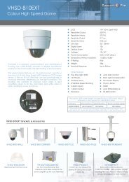
2. Panels and Remote Controller2.1 Front Panel1. LEDIndicators for POWER (LIGHT) and HDD (BLINK).2. Remote I/R SensorUsed to receive signal from I/R remote controller.- 8 -
2.2 Back Panel1. Video Input Connectors (1-4)Connect system cameras to these BNC connectors. The internal 75Ωtermination is always ON.2. Audio Input Connectors (AUDIO IN)The RCA connector accepts line-in audio signal supplied from externaldevices such as microphone amplifiers.3. Audio Output Connectors (AUDIO OUT)The connector supplies line-out audio signal to external devices such asspeakers. Recorded audio will be supplied from AUDIO OUT duringplayback.4. Main Video Output Connectors (MAIN VIDEO)Connect TV monitors to the BNC connector for main monitor display.5. VGA Connector (VGA)Connect VGA monitor to the D-SUB 15-pin female connector for mainmonitor display. Please note there won’t be video signal for MAINVIDEO BNC connector if VGA is connected.6. Ethernet ConnectorConnect this unit to a 10/100Base-T Ethernet network through this port.7. USB2.0 Connectors (USB)Connect one of the USB 2.0 connectors to USB mouse. Connect theother USB 2.0 connector to USB 2.0 compatible storage device, such asUSB 2.0 disk drive, DVD+RW, card reader, etc..8. Power Cord Inlet (DC 12V IN)Connect to DC +12V power source.- 9 -
2.3 Remote ControllerThe remote controller is an optional accessory to ease the user’s operations. You cando all the operations by the remote controller. The effective distance is about 10meters without any obstacle.The descriptions of the buttons are as below:1. Alpha-numeric Buttons (1-9, 0, *, #)Press these buttons for camera selection in most of the circumstances.These buttons can also be used to enter text and number in the waysimilar to most of the mobile phones.2. Alarm Reset ButtonPress this button to cancel alarm activation, and return the system to thecondition before the alarm was activated.3. REC ButtonPress this button to force manual recording. To stop manual recording,press it again.4. MUTE/NEXT ButtonPress this button to mute the audio.5. X2/GOTO ButtonIn full screen display, press this button for Digital Zoom (X2/X4).6. MENU / ESC ButtonPress this button to display the main menu or escape to the upper leveldisplay.7. Up/BS Button (▲/BS)Press this button to move the cursor or focus window in mostcircumstances. In text editing mode, this button is used as “backspace”key.- 10 -
8. Down/DEL Button (▼/DEL)Press this button to move the cursor or focus window in mostcircumstances. In text editing mode, this button is used as “del” key.9. Left/Right Buttons (◄,►)Press these buttons to move the cursor or focus window.10. ENTER ButtonThis button is used as “enter” key.11. (Split Windows) +/- Buttons ( )In split-window display, press these buttons for next/previous split-windowdisplay. In the others, press these buttons to change the contents.12. (Vol/Zoom) +/- Buttons ( / / )Press these buttons to change the volume.13. MODE ButtonPress this button to toggle between live mode and playback mode in mainscreen display. In some dialogs, this button is used as a miscellaneousfunction key. At playing, this button is used as “slow backward”.14. SEQ ButtonPress this button to switch to or return from SEQ display mode in mainscreen display. In some dialogs, this button is used as a miscellaneousfunction key. At playing, this button is used as “slow forward”.15. CALL ButtonPress this button to switch to or return from full screen display of the focuscamera in main screen display. In some dialogs, this button is used as amiscellaneous function key.16. SEARCH ButtonPress this button to display the search menu in main screen display. Insome dialogs, this button is used as a miscellaneous function key.17. Fast Backward Button ( )Press this button for fast backward playback.18. Fast Forward Button ( )Press this button for fast forward playback.19. Single Step Button ( )Press this button to play the recorded images frame by frame.20. Copy Button ( )- 11 -
Press this button to copy the playback images to the storage deviceconnected to the USB port. Press this button again to stop copying.21. Play/Pause Button ( )Press this button to play the recorded images, or pause the playback.22. Stop Button ( )Press this button to stop the playback.- 12 -
3. InstallationsThe installations described below should be made by qualified service personnel orsystem installers.3.1 Basic ConnectionsPlease refer to the following diagram for the connections.Please make sure to set the NTSC/PAL Selector Switch on the main boardaccording to the local TV system for the system to work correctly.• CamerasConnect the camera video input connectors to the video outputs from systemcameras or other composite video sources via coaxial cables. The internal 75Ωtermination is always ON.• Main monitorConnect the main monitor output connector (BNC) to a surveillance TV monitor,or connect the VGA output connector to a VGA monitor. The TV/VGAmonitor displays selected live or recorded cameras in any available split windowformat. Please note there won’t be video signal for MAIN VIDEO BNCconnector if VGA is connected.• PowerConnect DC 12V power source to DC 12V.- 13 -
3.2 Optional Connections• Audio inputConnect the audio input connector to the audio line-out from system cameras orother audio sources. Please make sure to associate the audio inputs with thecameras in Camera Setup as described in Section 6.1 accordingly.• Audio outputConnect the audio output connector to the audio line-in from speakers.• EthernetConnect the Ethernet connector to a standard twisted-pair Ethernet cable forremote access via LAN or internet. Please make sure to setup the relatedconfigurations as described in Section 6.5 Network Setup.• USB 2.0 disk drives, DVD+RW, card reader, etc.If the user wants to use USB2.0 peripheral device to retrieve important recordedimages and/or audio, please connect it to the USB2.0 port connector.• I/R remote controllerThe user may use I/R remote controller to control the digital video/audio recorder.- 14 -
4. Main Screen And Basic OperationsThe split-window screen, as shown above, is the main screen after system startup.There are two types of split-window screens, including 1-Window and 4-Window.The system will remember the last one before normal shutdown (as described inSection 5.5) of the system. In addition to the split windows, the system time isdisplayed on the lower-left corner, the system states on the lower-right corner, and therolling screen messages, if shown while certain event occurs, on the lower corner.The system states, from right to left, are described as the followings:(1) Recording percentage / total HDD size (GB),(2) Mute state – speaker icon shown for not mute, not shown for mute,(3) X2 state – X1, X2, or X4,(4) <strong>Manual</strong> record ON/OFF – REC icon shown for ON,(5) Backup state – Backup icon shown for backup, and(6) SEQ display ON/OFF or playback state – SEQ icon shown for SEQ display ON,other icons for different playback states.* If mouse is connected, the mouse operation icons will be shown when the mousecursor is moved to the bottom of the screen.* Recording icon & Motion for the camera may be shown after camera title.- 15 -
4.1 Text InputThere are certain circumstances that the system requires the user to enter text, such assystem login, camera title setup, and so on. Please follow the steps below to entertext:(1) Press ENTER to edit the highlighted option. The flashing cursor will be shownto indicate the editing point.(2) Press ◄► to move the cursor to the left/right.(3) Press code in text editing mode to change text case. (If this entry can acceptnumber only, pressing code will have no effects.) Indicators on the screen showthe current setting:123 = Number onlyabc = No capital lettersABC = All capital lettersCODE = Internal code for the selected language, such as Chinese, Japanese, etc.(4) Press a number key (1-9, 0) repeatedly until the character you want appears (1 for1 or space, 2 for 2, a/A, b/B, or c/C, etc.). If internal CODE is selected, aCODE box will be shown (after the first code is entered) for each new code to beentered. Please check the internal code table for the selected language. For2-byte code, e.g. Chinese or Japanese, the code accepted is from 0000 - FFFF.(5) Press mark to bring up a list of punctuation marks and special characters. Thehighlighted character in the list shows the selected one. Press ▲▼◄► tochange the selection.(6) If you make a mistake, press BS to remove the character to the left of the cursor,or press DEL to delete the character at the current cursor position.(7) In text editing mode, internal code box, and mark list, press ENTER to exit andsave changes, press ESC to exit without making changes.Note: If the user clicks on the left button of the mouse on the item, a KeyboardSimulator will be shown. Click on ‘#’ (or “abc”, ..) to change text case.Click on the alpha-numeric characters to enter text (or CODE). Click on ‘*’for mark.- 16 -
4.2 Login And LogoutThere are three password levels in the system, including Administrator (highest),Supervisor, and Operator (lowest). If the user does not login the system, he/shewill be treated as “Guest” and can only view live video display.The system allows up to 18 user accounts. The administrator can set up the loginname and password for each user. (Please refer to Section 6.3 for Password Setup.)The Operator can operate live video display, the Supervisor live video display, imageplayback and archive, and the Administrator everything.To login/logout the system,press MENU in split-windowdisplay to call up Menu display,and then press ENTER whenthe highlighted option isLogin/Logout to enterLogin/Logout display asshown.In Login/Logout display, follow the Text Input method described in Section 4.1 toenter the Login name and Password, press ▲▼ to highlight and select Login option,and then press ENTER to login the system. If the user wants to logout the system,just press ▲▼ to highlight and select Logout option, and then press ENTER. PressESC (Mouse: Right Click) to exit without making changes.There is one factory-preset login name/password aa/11 at Administrator level. Theuser can use it to login the system for the first time.Should the user have forgotten all the administrator-level passwords, pleasecontact the local dealer or installer to recover from it.4.3 Basic OperationsThe basic user’s operations after he/she has logged into the system are describedbelow:• Numeric (Mouse: )Press these buttons to switch to the full-window display for the camera.• Alarm Reset (Mouse: )Press this button to cancel alarm activation, i.e. reset the alarm outputs and silence- 17 -
the buzzer.• MODE (Mouse: ) (Administrator/Supervisor)In split-window display, press this button to change circularly the live/playbackmode for the focus window and the other windows that form a rectangle on thescreen.• SEQ (Mouse: )Press this button to switch to or return from SEQ display mode. In SEQ displaymode, each page in the sequence will be shown for the preset page dwelling time(about 5 seconds) sequentially, and SEQ icon will be shown on the lower-rightcorner of the screen.• CALL (Mouse: left-click in focus camera window)In split-window display, press this button to switch to or return from full screendisplay of the focus camera.• SEARCH (Mouse: ) (Administrator/Supervisor)In split-window display, press this button to display the search menus. Thesystem will remember the last one the user chose.• REC (Mouse: )Press this button to force manual recording. To stop manual recording, press itagain. All cameras will be recorded as if the scheduled record is A/V, and RECwill be shown on the lower-right corner of the screen if manual recording is ON.• MENU (Mouse: ) / ESC (Mouse: Right Click)In split-window display, press this button to display the versatile menu.• X2 (Mouse: )In full screen display, press this button to enter Digital Zoom mode. Please referto Section 4.4 Digital Zoom for the detailed operations in Digital Zoom mode.• ▲▼◄► (Mouse: left-click)Press these buttons to move focus. The title of the camera for the focus windowis highlighted as shown on the screen.• Vol+/- ( / ), MUTE (Mouse: )Press these buttons to control the volume.• +/- (Mouse: )Press these buttons to circulate up/down among the available split-windowdisplays.- 18 -
• ENTER (Mouse: )Press this button to display OSD display dialog. The user may enable/disableOSD display for certain fields in main screen. Press ENTER to save & exit, orESC to cancel.4.4 Digital ZoomThe system supports X2/X4 Digital Zoom function. To use this function, press X2button (Mouse: ) in full screen display to enter Digital Zoom mode. There willbe a zoom window shown in the video window as shown. The zoom window (a)will always be shown at zoom factor X1, (b) can be shown or hidden at zoom factorX2, and (c) will never be shown at zoom factor X4. The operations in Digital Zoommode are as below:• ▲▼◄► (Mouse: Click in the video window)Press these buttons to(a) move the zoom window if it’s shown in the video window, or(b) navigate the video window around if the zoom factor is X2 or X4.• ENTER (Mouse: Click in the video window)Press this button to zoom in the zoom window, from X1 to X2 or from X2 to X4,if the zoom window is shown in the video window.- 19 -
• X2 (Mouse: )Press this button to(a) show/hide the zoom window if the current zoom factor is X1/X2, or(b) zoom out the video window back to zoom factor X1 if the current zoom factoris X4.• ESC (Mouse: or Right Click)Press this button to escape from Digital Zoom mode, and return to normal fullscreen display. The video window will always return to zoom factor X1.- 20 -
5. Menu DisplayIn split-window display, press MENU (Mouse:shown.) to call up Menu display asThere are a variety of displays under Menu display. In Menu display and all thesubsequent displays, the items enabled are shown in black-colored text, and thosedisabled in white-colored text. Please refer to Section 4.2 for Login/Logout display.The user’s operations are described as the followings:• ▲▼◄►Press these buttons to change the highlighted item.• ENTER (Mouse: Click in the menu item)Press this button to enter the detailed display of the highlighted option. For thedetails of each option, please refer to the following sections.• ESC (Mouse: Right Click)Press this button to escape from Menu display, and return to split-window display.- 21 -
5.1 Video AdjustmentIn Menu display, press ▲▼◄► to change the highlighted option to VideoAdjustment, and then press ENTER to call up Video Adjustment display as shown.There are 4 items which can be adjusted, including Brightness, Contrast, Hue, andSaturation. The operations are as below:• ▲▼Press these buttons to select the items.• Numeric (Mouse: )Press these buttons to change the camera.• +/-Press these buttons to adjust the selected item.• SEQ (Mouse: )Press this button to reset the settings for this camera to factory default values.• CALL (Mouse: )Press this button to reset the settings for all cameras to factory default values.• MODE (Mouse: )Press this button to restore the values.- 22 -
• ESC (Mouse: or Right Click)Press this button to escape from this screen, and return to Menu display. Thesettings will be saved for future reference.- 23 -
5.2 VGA DisplayIn Menu display, press ▲▼◄► to change the highlighted option to VGA Display,and then press ENTER to call up VGA Display dialog as shown.There are 5 items which can be adjusted, including Resolution (only 1024x768 forthis model), Brightness, Contrast, Hue, and Saturation. The operations are as below:• ▲▼ (Mouse: Click in the respective item)Press these buttons to select the items.• +/-Press these buttons to adjust the selected item.• MODE (Mouse: Left click)Press this button to restore Brightness, Contrast, Hue, and Saturation to factorydefault values.• ESC (Mouse: Right Click)Press this button to escape from this screen, and return to Menu display. If thecontents have been modified, a Save dialog will be shown to ask the user to savethe changes, press ENTER to exit and save, ESC (Mouse: Right Click) to exitwithout saving.- 24 -
5.3 Backup DeviceIn Menu display, press ▲▼◄► to change the highlighted option to Backup Device,and then press ENTER to call up Backup Device display as shown below.The system supports a variety of USB 2.0 storage devices, including Storage DiskDrives and DVD Disc (including DVD+RW, DVD+R, and DVD-R). (DVD-RW isnot supported.) The operations are as below:• ▲▼◄►Press these buttons to select the items.• ESC (Mouse: Right Click)Press this button to escape from this screen, and return to previous display.• Connect/Disconnect – If the backup device is disconnected (as shown in CurrentStatus), please plug the device in the USB port and/or insert a DVD for DVDdevice, and then press ENTER (Mouse: Left click) to command the system toconnect with it. If the device is already connected (EX. R/W - Read/write, asshown in Current Status), please press ENTER (Mouse: Left click) tocommand the system software to disconnect with the device, and then unplug thedevice from the backup port.Note 1: DO NOT format the DVD disc for better performance and compatibility.Note 2: Before using USB pen drive, please format it to FAT32 file system byMS-Windows.Note 3: The backup device has to be connected by the system software before itcan be used to read/write. If it failed to connect, please unplug thedevice, and then plug the device in the USB port again.Note 4: Some backup devices may have compatibility problems. Please contactyour local dealer or installer for the supported devices.• BackupPress ENTER (Mouse: Left click) when this item is selected to backup the- 25 -
configurations of this unit to the corresponding USB device. The user mayenter the directory to backup the configurations to.• RestorePress ENTER (Mouse: Left click) when this item is selected to restore theconfiguration files in the corresponding backup device to this unit. The usermay enter the directory to restore the configurations from.Some USB 2.0 Devices TestedUSB-Storage Enclosures 5.25” –Macpower’s Alumni Prefect USB 2.0 - PF-U2MSUSB-Disk Storage –Transcend’s JetFlash 150/V60 Series, JetFlash V33 8GBApacer’s Handy Steno AH220Pretec’s i-Disk Wave 512M-BlackKingston’s DataTraveler USB Flash Driver(DTI/512FE)Kingston’s DataTraveler DT100 8GBSanDisk’s Cruzer micro USB Flash DriverSandisk’s Cruzer Titanium 4GB, Cruzer Contour 4GBSony’s MICRO VAULT Classic SeriesOCZ’s ATV 4GB, Rally2 4GBDVD Writer –Asus DRW-1608P SeriesPioneer DVR-A11, DVR-X152 SeriesBenQ EW200G SeriesLITEON LightScribe DVD Writer SHM-165H6S, 20X DVD Writer DX-20A4PSony DVD/CD Rewritable Drive Model DRX-810UL SeriesNEC DVD/CD Rewritable Drive Model ND-4550A SeriesHP dvd9404e External 18X Super Multi DVD Writer SeriesSome DVD Discs Tested – Only single-side, single-layer disc supportedInfomedia DVD+R 16XMitsubishi DVD+RW 1-4XPhilips DVD+RW 1-4XRitek DVD-R 8X, DVD+RW 1-4XVerbatim DVD+RW 1-4X- 26 -
5.4 Software Upgrade (Administrator)In Menu display, press ▲▼◄► to change the highlighted option to SoftwareUpgrade, and then press ENTER to call up Software Upgrade display as shown.The operations are as below:• ▲▼◄► (Mouse: Left click)Press these buttons to select the items.• ESC (Mouse: Right Click)Press this button to escape from this screen, and return to Menu display.Following is a brief description for each item and its specific operations:• Backup Device – press ENTER (Mouse: Left click) to call up Backup Devicedialog (if there’s no backup device connected).• Disk Storage – to select the disk storage to upgrade. Press +/- buttons to selectthe available storage.• Upgrade File – press ENTER (Mouse: Left click) to start the upgrade processwhen the highlighted file is a correct upgrade file. A confirmation dialog will beshown on the screen, press ENTER to confirm to upgrade the system software.Note : After the software is upgraded, the system will restart immediately. Thesplit window display will be shown after restart, please wait a moment.- 27 -
5.5 System Shutdown (Administrator)In Menu display, press ▲▼◄► to change the highlighted option to Shutdown, andthen press ENTER (Mouse: Left click) to shutdown the system. A confirmationdialog will be shown on the screen, press ENTER to confirm the shutdown. Thesystem will save all the files and all the states, and then display a power-off messagein the rolling screen message area. The user may power off the system safely whenthe power-off message is shown.- 28 -
6. Setup (Administrator)In Menu display, press ▲▼◄► to change the highlighted option to Setup, and thenpress ENTER to call up Setup Menu display as shown. (To enter Setup Menudisplay of the system, please login as Administrator first.)The user’s operations are described as the followings:• ▲▼◄►Press these buttons to change the highlighted item.• ENTER (Mouse: Left click)Press this button to enter the setup of the highlighted option. For the details ofeach option, please refer to the following sections.• ESC (Mouse: Right Click)Press this button to escape from Setup Menu display, and return to Menu display.If the user wants to reset all the settings to factory default values, he/she may press▲▼◄► to change the highlighted option to Factory Defaults, and then pressENTER. A confirmation dialog will be shown, press ENTER again to make thechanges, ESC (Mouse: Right Click) to not do it.If the user wants to clear the HDD, he/she may press ▲▼◄► to change thehighlighted option to Clear HDD, and then press ENTER. A confirmation dialogwill be shown, press ENTER to confirm, or ESC (Mouse: Right Click) to cancel.- 29 -
6.1 Camera SetupIn Setup Menu display, press ▲▼◄► to change the highlighted option to Camera,and then press ENTER (Mouse: Left click) to call up Camera Setup display.The Camera Setup allows the administrator to define the attributes for all cameras.There are up to 4 cameras which can be connected to the system.The general operations are as below:• ▲▼◄► (Mouse: Left click)Press these buttons to select the items. The display will scroll left/right if theselected item is not shown on the screen.• NumericPress these buttons to select the camera.• COPY ( )Press this button to copy all the settings - excluding detailed Motion settings,Title/Audio - of the focus camera to all the following cameras. (EX. focuscamera is 1, its settings will be copied to those of cameras 2-4.)• ESC (Mouse: Right Click)Press this button to escape from this screen, and return to Setup Menu display. Ifthe contents have been modified, a Save dialog will be shown to ask the user tosave the changes, press ENTER to exit and save, ESC (Mouse: Right Click) to- 30 -
exit without saving.Following is a brief description for each item and its specific operations:• REC Resolution – the record resolution for all the cameras in the system. ForNTSC, it can be 720x480, 720x240, or 360x240; for PAL, 720x576, 720x288, or360x288. Press +/- buttons to select the resolution.• Watermark – to record with digital watermark or not. If yes, all the recordedimages for all the cameras will have digital watermark embedded. PressENTER or +/- (Mouse: Left click) to check/uncheck this item. The defaultsetting is “ˇ” - checked.• Installed – whether this camera is installed or not. If installed, the followingitems will be settable. Press ENTER or +/- (Mouse: Left click) tocheck/uncheck this item. The default setting is “ˇ” - checked.• Title – The title (Max. 8 characters) of this camera. Please follow the Text Inputmethod described in Section 4.1 to modify this item.• Motion Detection – whether the motion detection of this camera is enabled or not.(Note : this field has no effect for the Smart Search information.) PressENTER or +/- to check/uncheck this item. The default setting is “ˇ” - checked.• Motion Settings.. – used to setup the motion settings, used for Motion Detectionor Smart Search, for this camera. Press ENTER (Mouse: Left click) inSettings.. to call up Motion Setup display for the camera. Please refer to Section6.1.1 for the details. Please note that if the Motion Detection is disabled, thedefault factory motion settings should work fine for Smart Search.• Covert – covert or not. If the camera is covert, the video of this camera can onlybe seen if the user has logged in as Administrator. Press ENTER or +/- (Mouse:Left click) to check/uncheck this item. The default setting is “–” - unchecked.• Audio – the AUDIO IN corresponding to this camera. The audio data for theselected AUDIO IN will be recorded with the video data for this camera. Press+/- buttons to select none (N/A) or AUDIO Input (1). The default setting is“N/A”.• Record Quality – the record quality for this camera. Press +/- buttons to selectthe value (1-9, with 1 the lowest (rough) quality, 9 the highest (fine) quality).• Event Record IPS – the IPS (Images Per Second) for this camera if Motion eventoccurs for this camera. This camera will be recorded at this rate for Post-recordtime since the event occurs. (Please refer to the following sections forPost-record time.) Press +/- buttons to select the value (0 – 25 (PAL) / 30- 31 -
(NTSC), discrete).Please note that the total Event Record IPS should not exceed the systemrecording capacity (NTSC: 240/CIF, 120/Half-D1, 60/Full-D1; PAL: 200/CIF,100/Half-D1, 50/Full-D1), or the system will lower the actual rate automaticallyat recording.• Normal Record IPS – the normal record IPS for this camera. This camera willbe recorded at this rate if no event occurs. Press +/- buttons to select the value(0 – Event Record IPS for this camera, discrete).6.1.1 Motion SetupIn Camera Setup, press ENTER to call up Motion Setup as shown when thehighlighted option is Motion Settings.. of the camera to setup. The Motion setupallows the administrator to define how the system responds to the detected motion forthe camera.The general operations are as below:• ▲▼ (Mouse: Left click)Press these buttons to select the items.• NumericPress these buttons to select the camera.• COPY ( )Press this button to copy the Motion settings, including Detection settings, of thefocus camera to all the following cameras. (EX. focus camera is 1, its Motion- 32 -
settings will be copied to those of cameras 2-4.)• ESC (Mouse: Right Click)Press this button to escape from this screen, and return to Camera Setup display.If the Save dialog is shown, press ENTER to exit and save, ESC (Mouse:Right Click) to exit without saving.Following is a brief description for each item and its specific operations:• Duration – response duration to define at most how long (in seconds) the Buzzerwill keep being triggered after motion is detected for this camera. However, theBuzzer will be reset immediately once the camera returns to normal. Press +/-buttons to adjust the value (3 seconds - 60 minutes, discrete, ‘-‘ for ‘Forever’).• Pre-record – to define how long before motion is detected this camera shall beintensively recorded at Event Record IPS. Press +/- buttons to adjust the value(0-10 seconds, discrete). Please note that the actual pre-record time may beshorter than the value set if the total size of the pre-record pictures exceeds thepre-record buffer size of the system.• Post-record – to define how long after motion is detected this camera shall beintensively recorded at Event Record IPS. Press +/- buttons to adjust the value(0 second - 60 minutes, discrete).• Buzzer – to activate the internal Buzzer or not when motion of this camera isdetected. Press ENTER or +/- (Mouse: Left click) to check/uncheck this item.The default setting is “ˇ” - checked.• Log – to log to event logs or not. Press ENTER or +/- to check/uncheck thisitem. The default setting is “ˇ” - checked.• E-mail – to send the event e-mail to remote station or not. The e-mail will besent to the predefined receivers when the event is triggered. Press ENTER or+/- to check/uncheck this item. The default setting is “–” - unchecked.• Detection Settings.. – used to setup the motion detection settings, includingdetection area and sensitivity, when motion is detected for this camera. Pleasenote that the detection area and sensitivity are also used for the Smart Searchinformation. There won’t be any Smart Search information stored outsidethe detection area. So, it’s better to enable the whole area if the motiondetection for the camera is disabled (and only Smart Search is used). PressENTER in Settings.. to call up Motion Detection Setup (as shown) for thiscamera. In Motion Detection Setup, the video area is divided into many smallgrids, and the area with gray grids is the area which will be detected for motion,while transparent grids not detected for motion. Besides, there is a (yellow)Mask window.- 33 -
Following is a brief description for the operations:• Numeric (Mouse: )Press these buttons to select the camera.• ▲▼◄►Press these buttons to move the Mask window.• +/- (Mouse: Left click and drag)Press these buttons to resize the Mask window.• ENTER (Mouse: )Press this button to set/reset the area under the Mask window.• MODE (Mouse: )Press this button to set/reset the whole video area.• SEQ (Mouse: ) / CALL (Mouse: )Press this button to decrease/increase the sensitivity, 1 – 10, for the motiondetection of this camera.• Vol+/- ( / ) (Mouse: )Press this button to increase/decrease the “number of grids treated as motion”- 34 -
for the motion detection of this camera.• SEARCH (Mouse: )Press this button to test the motion detection of this camera. The detectedmotion will be shown on the screen. Press this button again to stop testing.• ESC (Mouse: or Right Click)Press this button to escape from Motion Detection Setup, and return to MotionSetup.- 35 -
6.2 Scheduled Record SetupIn Setup Menu display, press ▲▼◄► to change the highlighted option toScheduled Record, and then press ENTER to call up Scheduled Record Setup.The Scheduled Record Setup allows the administrator to define when and how torecord for the system. In Scheduled Record Setup, there are Four SelectableRecording Modes: Motion+Normal, Motion, Normal, and No Record. Video &Audio are all recorded for the selectable Recording Modes except “No Record”.The operations are as below:• ▲▼◄►Press these buttons to move the focus.• Numeric 1-4 (Mouse: Left click)Press these buttons to select the active Recording Mode. The user may alsopress ENTER when the focus is on the Recording Mode to activate it. TheRecording Modes are : “1” – Motion+Normal, “2” – Motion, “3” – Normal,“4” – No Record, and Others (which is not selectable).• +/- (Mouse: Left click and drag)Press these buttons to set the focus interval (one grid for one hour)upwardly/downwardly to the Active Recording Mode. The user may also pressENTER to set the focus interval to the Active Recording Mode.• ESC (Mouse: Right Click)- 36 -
Press this button to escape from this screen, and return to Setup Menu display. Ifthe Save dialog is shown, press ENTER to exit and save, ESC (Mouse: RightClick) to exit without saving.- 37 -
6.3 Password SetupIn Setup Menu display, press ▲▼◄► to change the highlighted option to Password,and then press ENTER to call up Password Setup as shown.The Password Setup allows the administrator to add new users, delete existing ones,and/or modify the user’s name, password, and/or level.There are three default password levels in the system, including Administrator(highest), Supervisor, and Operator (lowest). The Operator can operate live videodisplay, the Supervisor live video display, image playback and archive, and theAdministrator everything. Beside the default password levels, the user can also set“Customized” user level as described in the following paragraphs. The systemallows up to 18 user accounts.There is one factory-preset login name/password aa/11 at Administrator level. Theuser can use it to login the system for the first time.The general operations are as below:• ▲▼◄► (Mouse: Left click)Press these buttons to select the items. The display will scroll up/down if theselected item is not shown on the screen.• MODE => Select/Deselect as default (Mouse: Left click)Press this button to select this user as the default one at login, or deselect if thisuser is the default login user. An asterisk (*) will be shown preceding thenumber for the default login user. And this login name/password will be thedefault one each time the login dialog is shown, so the user doesn’t bother to enterthe text to login the system.- 38 -
• ESC (Mouse: Right Click)Press this button to escape from this screen, and return to Setup Menu display. Ifthe Save dialog is shown, press ENTER to exit and save, ESC (Mouse: RightClick) to exit without saving.Following is a brief description for each item and its specific operations:• Guest Level – the access level (Administrator, Supervisor, Operator, or -)without login the system. Press +/- buttons to change the level.• Auto Logout – auto logout, if there’s no user’s operation in 1 minute to 24 hours,or not (“-“). Press +/- buttons to change the value.• Login Name – please follow the Text Input method described in Section 4.1 tomodify this item.• Password – this item accepts numbers only. Please follow the Text Inputmethod described in Section 4.1 to modify this item.• Level – the password level (Administrator, Supervisor, Operator, orCustomized) for this user. Press +/- buttons to change the level.• Adv. – press ENTER (Mouse: Left click) to call up Advanced <strong>User</strong> Setup asshown below.The Advanced <strong>User</strong> Setup allows the administrator to setup each user’s detailedaccess right of the system.The general operations are as below:• ▲▼◄►- 39 -
Press these buttons to move the focus. If the selected item is not shown onthe screen, the screen will scroll up or down.• ESC (Mouse: Right Click)Press this button to escape from this screen, and return to Password Setupdisplay. The Password Setup contents will be updated accordingly.Following is a brief description for each item and its specific operations:• Monitor Channel 1-4 – the user can only monitor those channels “checked”.Press ENTER or +/- (Mouse: Left click) to check/uncheck this item.• X2 – to enable the user to do X2 operation for live/playback video if“checked”. Press ENTER or +/- (Mouse: Left click) to check/uncheckthis item.• OSD Display – to enable the user to change OSD Display if “checked”.Press ENTER or +/- (Mouse: Left click) to check/uncheck this item.• Video Adjustment – to enable the user to do video adjustment operation if“checked”. Press ENTER or +/- (Mouse: Left click) to check/uncheckthis item.• VGA Display – to enable the user to change VGA settings if “checked”.Press ENTER or +/- (Mouse: Left click) to check/uncheck this item.• Playback – to enable the user to playback video/audio if “checked”. PressENTER or +/- (Mouse: Left click) to check/uncheck this item.• Backup – to enable the user to backup video/audio if “checked”. PressENTER or +/- (Mouse: Left click) to check/uncheck this item.• Configuration Backup/Restore – to enable the user to backup/restoreconfigurations if “checked”. Press ENTER or +/- (Mouse: Left click) tocheck/uncheck this item.• Setup Camera – to enable the user to do Camera Setup if “checked”. PressENTER or +/- (Mouse: Left click) to check/uncheck this item.• Setup Scheduled Record – to enable the user to do Scheduled Record Setupif “checked”. Press ENTER or +/- (Mouse: Left click) to check/uncheckthis item.• Setup Password – to enable the user to do Password Setup if “checked”.Press ENTER or +/- (Mouse: Left click) to check/uncheck this item.- 40 -
• Setup System – to enable the user to do System Setup if “checked”. PressENTER or +/- (Mouse: Left click) to check/uncheck this item.• Setup Network – to enable the user to do Network Setup if “checked”.Press ENTER or +/- (Mouse: Left click) to check/uncheck this item.• Setup Factory Defaults – to enable the user to restore factory defaults to allsetup related configurations if “checked”. Press ENTER or +/- (Mouse:Left click) to check/uncheck this item.• Software Upgrade – to enable the user to upgrade DVR software if“checked”. Press ENTER or +/- (Mouse: Left click) to check/uncheckthis item.• Shutdown – to enable the user to shutdown the DVR if “checked”. PressENTER or +/- (Mouse: Left click) to check/uncheck this item.- 41 -
6.4 System SetupIn Setup Menu display, press ▲▼◄► to change the highlighted option to System,and then press ENTER to call up System Setup as shown.The System Setup allows the administrator to set the system time, time zone, timesynchronization, language, etc.The general operations are as below:• ▲▼◄► (Mouse: Left click)Press these buttons to select the items.• ESC (Mouse: Right Click)Press this button to escape from this screen, and return to Setup Menu display. Ifthe Save dialog is shown, press ENTER to exit and save, ESC (Mouse: RightClick) to exit without saving. Please note that if the selected language ischanged, the user will be asked to reboot the system for the newly selectedlanguage to take effect.Following is a brief description for each item and its specific operations:• Time Zone – press +/- buttons to select the time zone for the system. Pleaserefer to Appendix B for the time zone table.• Daylight Saving Time – press ENTER or +/- to check/uncheck this item. Thedefault value is set by selecting a different time zone, but the user maycheck/uncheck this item if the default setting is checked.- 42 -
• System Time –• Synchronization – time synchronized with TSP Server or not. PressENTER or +/- to check/uncheck this item. The default setting is “–” -unchecked.• TSP Server – TSP (Time Synchronization Protocol) server name if TimeSynchronization is enabled. The system will try to do time synchronizationwith the specified TSP server at the system preset interval. Please follow theText Input method described in Section 4.1 to modify this item.• Date – system date.Press +/- buttons to modify each of these items.• Time – system time. Press +/- buttons to modify each of these items.• Display Format – format used for the system time displayed on the lower-leftcorner of the main screen. Press +/- buttons to select the desired format.• Language – press +/- buttons to select the language for the system. Thelanguages supported include: English, Russian, Simplified Chinese,Spanish, Traditional Chinese, Polish, Turkish, etc.• Protection Key – the protection key for the remote access of the system. Pleasefollow the Text Input method described in Section 4.1 to modify these items.Note: This protection key will be used for authentication when any remote stationwants to connect with the system from Ethernet interface, either LAN orinternet. So, the same protection key must be entered to install the remotesoftware if it is to be used to access the system.- 43 -
6.5 Network SetupIn Setup Menu display, press ▲▼◄► to change the highlighted option to Network,and then press ENTER to call up Network Setup as shown.The Network Setup allows the administrator to setup all Ethernet network relatedparameters. Please check with your network administrator to set these parameterscorrectly.The general operations are as below:• ▲▼◄► (Mouse: Left click)Press these buttons to select the items.• ESC (Mouse: Right Click)Press this button to escape from this screen, and return to Setup Menu display. Ifthe Save dialog is shown, press ENTER to exit and save, ESC (Mouse: RightClick) to exit without saving.Following is a brief description for each item and its specific operations:• Net Type – Static IP, PPPoE, or DHCP. DHCP can only be used for intranet(LAN) access, while Static IP and PPPoE can be used for both internet & intranetaccess. Press +/- buttons to change the Net Type.• IP Address – Ethernet IP address for the system. To get the static IP address,please contact your local ISP (Internet Service Provider). Please follow the TextInput method described in Section 4.1 to modify these items.- 44 -
• Net Mask – Net Mask for the IP address. Please follow the Text Input methoddescribed in Section 4.1 to modify these items.• Gateway – Gateway IP address for the system. Please follow the Text Inputmethod described in Section 4.1 to modify these items.• DNS – DNS (Domain Name Server) IP address for the system. Please followthe Text Input method described in Section 4.1 to modify these items.• <strong>User</strong>name – PPPoE username for the system if PPPoE is used. Please followthe Text Input method described in Section 4.1 to modify this item.• Password – PPPoE password for the system if PPPoE is used. Please follow theText Input method described in Section 4.1 to modify this item.• DDNS Type – Dynamic, Static, Custom DDNS (Dynamic Domain Name Server)type, etc. Please contact your local DDNS Service Provider to get the DDNSURL, username, and password. Press +/- buttons to change this item. Ifinternet is accessible, the user can select “Fly2DNS” for free built-in DDNSserver, URL/DDNS <strong>User</strong>name/DDNS Password will be filled in automaticallyafter the user exits and saves the settings. The user can change the prefix ofthe URL afterwards.• URL – the URL (Uniform Resource Locators) for the system if PPPoE is used.Please follow the Text Input method described in Section 4.1 to modify this item.• DDNS <strong>User</strong>name – DDNS username for the DVR for Static IP, PPPoE, or DHCP.Please follow the Text Input method described in Section 4.1 to modify this item.• DDNS Password – DDNS password for the DVR for Static IP, PPPoE, or DHCP.Please follow the Text Input method described in Section 4.1 to modify this item.• E-mail – press ENTER (Mouse: Left click) to call up E-mail Setup. Pleaserefer to Section 6.5.1 for the details.• Adv. – press ENTER (Mouse: Left click) to call up Advanced Network Setup.Please refer to Section 6.5.2 for the details.Note: If DDNS Type is FreeDNS, the URL must be appended with “,hash”,where hash is extracted from the grab URL batch file that is downloadedfrom freedns.afraid.org.- 45 -
6.5.1 E-mail SetupIn Network Setup, press ENTER to call up E-mail Setup as shown when thehighlighted option is E-mail.The E-mail Setup allows the administrator to set e-mail related parameters. Whenan event occurs and E-mail is enabled for the corresponding action, an e-mail will besent based on the parameters set here.The general operations are as below:• ▲▼ (Mouse: Left click)Press these buttons to select the items.• ESC (Mouse: Right Click)Press this button to escape from this screen, and return to Network Setup display.If the Save dialog is shown, press ENTER to exit and save, ESC (Mouse:Right Click) to exit without saving.Following is a brief description for each item and its specific operations:• SMTP Server – SMTP mail server name. Please follow the Text Input methoddescribed in Section 4.1 to modify this item.• SMTP Port – the SMTP port for e-mail transmission. The default value is 25.Please follow the Text Input method described in Section 4.1 to modify this item.• Authentication – whether the SMTP mail server requires authentication. PressENTER or +/- to check/uncheck this item.- 46 -
• <strong>User</strong>name – username if the SMTP mail server requires authentication. Pleasefollow the Text Input method described in Section 4.1 to modify this item.• Password – password if the SMTP mail server requires authentication. Pleasefollow the Text Input method described in Section 4.1 to modify this item.• Mail From – the e-mail address of this DVR unit, i.e. the sender of the e-mailsoriginated from the triggered events. Please follow the Text Input methoddescribed in Section 4.1 to modify this item.• Mail To #1-5 – the receivers’ e-mail addresses. The system can send the e-mailsoriginated from the triggered events to up to 5 different receivers. Please followthe Text Input method described in Section 4.1 to modify these items.• Attachment – attached picture for the e-mail sent. The value could be (N/A,Original picture, QCIF picture). Press +/- buttons to change this item.- 47 -
6.5.2 Advanced Network SetupIn Network Setup, press ENTER to call up Advanced Network Setup as shown whenthe highlighted option is Adv..The Advanced Network Setup allows the administrator to set advanced networkparameters. If the user is not familiar with network administration, please DONOT modify the items in this dialog.The general operations are as below:• ▲▼ (Mouse: Left click)Press these buttons to select the items.• ESC (Mouse: Right Click)Press this button to escape from this screen, and return to Network Setup display.If the Save dialog is shown, press ENTER to exit and save, ESC (Mouse:Right Click) to exit without saving.Following is a brief description for each item and its specific operations:• Control Port – the control port for remote access. The default value is 67.Please follow the Text Input method described in Section 4.1 to modify this item.• Data Port – the data port for remote access. The default value is 68. Pleasefollow the Text Input method described in Section 4.1 to modify this item.• HTTP Port – the HTTP (web page) port for remote access. The default value is- 48 -
80. Please follow the Text Input method described in Section 4.1 to modify thisitem.• WAP Picture Quality – the WAP picture quality if WAP access is supported forthe DVR. Press +/- buttons to change the value.• Video Stream – network live video stream is the same as “Record” stream, or theothers for dual streaming. If dual streaming is used, the total system recordingrate will be lowered. The default value is “Record”, which means that dualstreaming is not used. Press +/- buttons to change the value. To use dualstreaming in I.E. or CMS, the user must select “Extra” in “Video Stream” in the“Device List” in remote PC (Sec. 8.1).• IP Filter #1-4 – the IP filters #1-4 for remote access. Only those PCs with IPaddresses matching one of the IP filters can access the DVR remotely. Pleasefollow the Text Input method described in Section 4.1 to modify these items.Note: If the Control Port or Data Port is not available or accessible duringremote access, the system will reset the ports to their default values, i.e.67/68.- 49 -
7. Search/Playback/Archive (Administrator, Supervisor)There are four ways to search the recorded video/audio for playback:(a) Search by time,(b) Search by event,(c) Smart search, and(d) Search archived files.In split-window display, press SEARCH button (Mouse:Menu display as shown.) to call up SearchThe user’s operations are described as the followings:• ▲▼◄►Press these buttons to change the highlighted item.• ENTER (Mouse: Left click)Press this button to enter the corresponding Search display of the highlighted item.The Search displays and their operations are described in the following sections,followed by the playback operations of the searched video/audio.• ESC (Mouse: Right Click)Press this button to escape from Search Menu display, and return to split-windowdisplay.Note: In split-window display, the user can press PLAY button (Mouse: ) tocall up Instant Playback Menu, and then select the time for instantplayback.- 50 -
7.1 Search By TimeThe screen for Search By Time isshown on the right side:The Status field will show the‘Recorded from’ time based on theselected Video/Audio beforesearching.The general operations are as below:• ▲▼ (Mouse: Left click)Press these buttons to select theitems.• ESC (Mouse: Right Click)Press this button to escape from this screen, and return to split-window display.• Play Button ( ) (Mouse: Left click)Press this button to start playing the recorded video/audio with the selected searchtime and video/audio type. If there’s no camera in playback mode, all thecameras in the current split window will be set to playback mode.• Copy Button ( ) (Mouse: Left click)Press this button to backup (copy) the selected type of recorded video/audiostarting from the Search Time (described below) in the HDD to the connectedbackup device without playback. The Backup display (described in Section 7.5)will be shown. Please note that this kind of backup is performed in thebackground, and the user can still do almost all the operations.Following is a brief description for each item and its specific operations:• Search Time – (Year, Month, Date, Hour, Minute) for the recorded video/audio.The playback (or backup) will start from the time entered here when the userpress the playback buttons (or Copy button) later. Press +/- buttons to modifyeach item.• Video/Audio – (Motion, Video Loss, Normal). Check the types of the recordedvideo/audio you want to search for playback. Press ENTER or +/- tocheck/uncheck each item.- 51 -
7.2 Search By Event / Log DisplayThe screen for Search By Event - Log display, is shown below:There are three different types of event logs, including Motion, Video Loss, andSystem. And up to 3000 most recent event logs can be stored in the system.The general operations are as below:• ▲▼◄► (Mouse: Left click)Press these buttons to select the items.• ESC (Mouse: Right Click)Press this button to escape from this screen, and return to split-window display.• MODE => Refresh (Mouse: Left click)Press this button to refresh the log display. If there are new event logs after thescreen is last updated, the log list shown will be updated accordingly.• SEARCH => Log (Mouse: Left click)Press this button to export the event log to backup device. The Log File dialogwill be shown as below.- 52 -
Please select the backup device, and enter the directory name you want, and thenpress COPY to copy the event log to the selected backup device.• SEQ => Page Up (Mouse: Left click)• CALL => Page Down (Mouse: Left click)Press SEQ/CALL to Page Up/Down the Log display.• Numeric (ENTER) (Mouse: Left click in the page number shown)Press these buttons to select the display page of the event logs, the log list willalso be updated.Following is a brief description for each item and its specific operations:• Event Type – the type of the events (Motion, Video Loss, System) to be shownin the log list. The Event Type “System” includes all system related events, suchas power on/off, and will not trigger recording. Press ENTER or +/- tocheck/uncheck the event type for the log list.• Source ID – the source which triggered the event. For Motion and Video Loss,it’s the camera number. It’s used to filter the events to be shown in the log list.Press ENTER or +/- to check/uncheck each item. You may check/uncheck“All” for faster operation.• Log List – the event logs according to the Event Type and Source ID selected.The user may (1) press ENTER (Mouse: Left click) to select/deselect thehighlighted log in this list, (multiple logs can be selected in this way) (2) pressPlay Buttons ( , ) (Mouse: Left click) to playback all the selected logs,or (3) press Copy Button ( ) (Mouse: Left click) to backup (copy) all theselected recorded video/audio to the connected backup device without playback.The Backup display (described in Section 7.5) will be shown. Please note thatthis kind of backup without playback is performed in the background, andthe user can still do almost all the operations. Please refer to Section 7.6Playback For Search By Event for the detailed operations for event playback.- 53 -
7.3 Smart SearchThe screen for Smart Search is shown below:The Status field will show the ‘Recorded from’ time in the HDDs before searching orthe search result after searching.The general operations are as below:• ▲▼◄► (Mouse: Left click)Press these buttons to select the items.• ESC (Mouse: Right Click)Press this button to escape from this screen, and return to split-window display.• SEARCH / MODE (Mouse: Left click)Press this button to start searching the recorded video/audio with the selectedsearch time, camera, and motion masks. The search result will be shown on theright half of this dialog. To prevent the system from overloading by SmartSearch, up to 500 matched files or 200 GB of HDD storage for each recordpartition, alarm or normal, from the start time will be searched.• SEQ => Page Up (Mouse: Left click)• CALL => Page Down (Mouse: Left click)Press SEQ/CALL to Page Up/Down the Matched file display.• Numeric (ENTER) (Mouse: Left click in the page number shown)- 54 -
Press these buttons to select the display page of the matched files in the list.Following is a brief description for each item and its specific operations:• Camera ID – the camera to be searched for matched files. Its title is shown onits right side. Press +/- buttons to change the camera ID.• Start/End Time – (Year, Month, Date, Hour, Minute) for the recordedvideo/audio. The files will be searched from the start time to the end timeentered here when the user press the SEARCH/MODE button later for thematched files. Press +/- buttons to modify each item.• Matched file List – the matched files (HDD ID & time are shown) according tothe selected search time, camera, and motion masks. The files are shown fromthe oldest to the newest, and its page number is shown on the lower-left corner.The user may (1) press ENTER to enter Smart Search Playback display of theselected matched file in this list, (2) press Play Button ( ) (Mouse: Leftclick twice) to playback it directly, or (3) press Copy Button ( ) (Mouse:Left click) to backup (copy) the selected recorded video/audio to the connectedbackup device without playback. The Backup display (described in Section 7.5)will be shown. Please note that this kind of backup without playback isperformed in the background, and the user can still do almost all theoperations. Please also note that the playback (or backup) can walk acrossall the matched files. Please refer to Section 7.7 Playback For Smart Search forthe detailed operations for smart search playback.• Area.. – the motion areas for the camera to be searched for matched files. Thefiles with motion covering all the motion areas will be selected as matched.Press ENTER (Mouse: Left click) in Area.. to call up Motion Area Settingscreen as shown below. In Motion Area Setting screen, the video area is dividedinto many small grids, and the gray areas shown on the screen are the areaswhich will be checked for matched motion. Besides, there is a (yellow) Maskwindow. Please note that based on the search algorithm, there will be morematched files for smaller areas.- 55 -
Following is a brief description for the operations:• ▲▼◄►Press these buttons to move the Mask window.• +/- (Mouse: Left click and drag)Press these buttons to resize the Mask window.• ENTER (Mouse: )Press this button to set/reset the area under the Mask window. The area setwill be shown with semi-transparent gray area.• MODE (Mouse: )Press this button to set/reset the whole video area.• ESC (Mouse: or Right Click)Press this button to escape from Motion Area Setting screen, and return toSmart Search screen.- 56 -
7.4 Search Archived FilesThe screen for Search Archived Files is shown below:The operations are as below:• ▲▼◄► (Mouse: Left click)Press these buttons to select the items.• ESC (Mouse: Right Click)Press this button to escape from this screen, and return to split-window display.Following is a brief description for each item and its specific operations:• Backup Device – press ENTER (Mouse: Left click) to call up Backup Devicedialog (if there’s no Backup device connected).• Disk Storage – to select the disk storage to search the archived files. Press +/-buttons to select the available storage.• Archived File List – the archived files in the selected Disk Storage. Pleaseselect the file, and then press ENTER to enter Archived File Playback display ofthe selected file in this list, or press Play Button ( ) (Mouse: Left clicktwice) to playback it directly. Please refer to Section 7.8 Playback For ArchivedFiles for the detailed operations. Besides, you may press MODE (Mouse: Leftclick) to delete the selected file.Note : The format of the filename is camNN-YYYYMMDD-hhmmss.h264, whereNN stands for camera number, YYYY year, MM month, DD date, hhhour, mm minute, and ss second.- 57 -
7.5 Playback/Archive For Search By TimeIn split-window display, press MODE button (Mouse: ) to change circularly thelive/playback mode for the focus window and the other windows that form a rectangleon the screen. The video windows for the windows in playback mode are grayed,while those in live mode display live video.Please refer to Section 4.3 Basic Operations for how to change the camera(s) in theplayback windows(s). After the playback windows and cameras are all set as youwant, you may use the following buttons to control the playback:• Play/Pause ( ) (Mouse: )Press this button to play the recorded video/audio searched at forward speed 1X,or pause the playback. If the playback is paused, press this button again toresume playing. Note that audio can only be played at forward speed 1X.• Stop ( ) (Mouse: )Press this button to stop playing the recorded video/audio.button later, the playback will start from the beginning.If the user press• Fast Forward( /► on remote controller, ► on front panel) (Mouse: ),Slow Forward Button (SEQ) (Mouse: ) => (Mouse: to toggle)Press this button for fast/slow forward playback. Each time this button ispressed, the forward playback speed will become faster/slower, from 2X, 4X, 8X,up to 64/16X, and then back to 2X.• Fast Backward( /◄ on remote controller, ◄ on front panel) (Mouse: ),Slow Backward Button (MODE) (Mouse: ) => (Mouse: to toggle)Press this button for fast/slow backward playback. Each time this button ispressed, the backward playback speed will become faster/slower, from 2X, 4X,8X, up to 64/16X, and then back to 2X.• Single Step ( /▼ on remote controller, ▼ on front panel) (Mouse: )Press this button to play the recorded images frame by frame.• Copy ( ) (Mouse: )Press this button to copy or stop copying the playback video/audio to the storagedevice connected to the USB port. The Backup display will be shown as below.- 58 -
Following is a brief description for the operations in Backup display:• ▲▼◄► (Mouse: Left click)Press these buttons to select the items.• Copy Button ( ) (Mouse: Left click)Press this button to start backup (copy) or apply the revised settings if it’scopying, and return to the previous display. There will be a Copy icon onthe lower-right corner indicating that the selected video/audio is beingarchived to the storage device. For DVD disc, the files won’t be written tothe disc until the storage size reaches 1 GB or the user stop copying.Writing to the disc may take more than 1 minute for every 100 MB(depending on the disc type).• Stop ( ) (Mouse: Left click)Press this button to stop copying and return to the previous display. TheCopy icon will be disappeared.• ESC (Mouse: Right Click)Press this button to cancel, and return to the previous display.The description for each item and its specific operations is as below:• Backup Device – the backup device connected to the system. Press ENTER(Mouse: Left click) on the left button to call up Backup Device dialog ifthere’s no backup device connected. Press +/- buttons on the right selectionto select the connected device. Please follow the steps described in Section5.3 Backup Device to connect the backup device before copying.• Backup Speed – 1-9, with 1 the lowest speed, 9 the highest speed. Press +/-buttons to select the value.- 59 -
• Directory – the directory to store the archived files. Please follow theText Input method described in Section 4.1 to input the directory.• Cameras – the video/audio of the cameras to be archived.or +/- to select/deselect each of the selectable cameras.Press ENTER• End Time – (Year, Month, Date, Hour, Minute) for the recordedvideo/audio for the backup without playback of Search By Time. Thefiles will be backup from the start time to the end time when the user press theCOPY button (Mouse: Left click) to start copying. Press +/- buttons tomodify each item.• Search Button ( ) (Mouse: )Press this button to display the playback slider bar as shown below.The left-most is the start time and its slider, the right-most is the end time and itsslider, and the middle is the current playback time and its slider. Following is abrief description for the operations in playback slider bar:• ▲▼ (Mouse: Left click)Press these buttons to select the focus slider.• ◄► repeatedly & ENTER Button (Mouse: Left click and drag)Press ◄► repeatedly and then press ENTER to move the focus slider to anew time. The whole playback slider bar will be updated accordingly.• Playback Buttons ( , , , , )These playback buttons are still operational as described above.• ESC (Mouse: Right Click)Press this button to not show the playback slider bar.Except the playback buttons, the user can still do all the other operations insplit-window display as if there is no playback. Please refer to Section 4.3 BasicOperations for the operations of the other buttons.Note : For each camera and each backup, a batch file will be generated as well asthe backup files. A directory “/SelfPlayer” will also be generated if it’snot existing in the backup storage device. The user can use the batch- 60 -
file to self-playback the corresponding backup files in a PC. If the PChas not been installed with the required player components, thosecomponents will be installed by running the batch file except WindowsVista. For Windows Vista, please run /SelfPlayer/SelfPlayerInstall.exemanually to install the required player components. To copyself-playback files, please copy the batch file and the backup files to thedestination directory, and copy the whole directory “/SelfPlayer” to theroot directory of the destination device.- 61 -
7.6 Playback/Archive For Search By EventIn Log display, press Play Buttons ( ) (Mouse: Left click) to playback theselected logs. This display is the same as full screen display of the main display, andthe playback buttons are effective.The operations are as below:• Playback Buttons ( , , , , , , ENTER, MODE, SEQ,SEARCH) (Mouse: , ..)These buttons are all the same as in Section 7.5 Playback/Archive For Search ByTime.• The Other ButtonsAll the other buttons are the same as in Section 4.3 Basic Operations.7.7 Playback/Archive For Smart SearchIn Smart Search display, press ENTER to enter Smart Search Playback display of theselected matched file, or press Play Button ( ) (Mouse: Left click twice) toplayback it directly. Please note that the playback can walk across all the (up to500 per record partition) matched files. So, it’s not necessary for the user torepeat the process of Smart Search & Playback just for a single file. This display isthe same as full screen display of the main display, and the playback buttons areeffective.The operations are as below:• Playback Buttons ( , , , , , , ENTER, MODE, SEQ,SEARCH) (Mouse: , ..)These buttons are all the same as in Section 7.5 Playback/Archive For Search ByTime.• CALLAt playing the video, press this button to call up (show) or hide the MotionAreas set by the user.• The Other ButtonsAll the other buttons are the same as in Section 4.3 Basic Operations.- 62 -
7.8 Playback For Archived FilesIn Search Archived Files display, press ENTER to enter Archived File Playbackdisplay of the selected file, or press Play Button ( ) (Mouse: Left click twice)to playback it directly. This display is the same as full screen display of the maindisplay, and the playback buttons are effective.The operations are as below:• Playback Buttons ( , , , , , ENTER, MODE, SEQ, SEARCH)(Mouse: , ..)These buttons are all the same as in Section 7.5 Playback/Archive For Search ByTime. Please note that COPY button () is not effective in this display.• The Other ButtonsAll the other buttons are the same as in Section 4.3 Basic Operations.- 63 -
8. Remote Access8.1 PC Remote AccessThe digital video/audio recorder can be accessed by using a web browser installed ona PC if this unit is connected to a network, either internet or intranet.Before Logging OnBefore accessing this unit through web browser, please make sure the followings (Formost PCs, only step 4 & 7 is needed!):1. This unit is connected to the network correctly, and the configurations are all setupcorrectly. Please refer to Section 6.5 Network Setup for the detailedconfigurations.2. DirectX ® End-<strong>User</strong> Runtime 9.0 or above has been installed in your PCsuccessfully. If not, please logon to http://www.microsoft.com to get the freedownload of it.3. Windows XP KB319740 Package has been installed in your PC successfully if thePC is running Windows XP SP2. If not, please logon tohttp://www.microsoft.com/downloads/details.aspx?FamilyId=9B5EDFC8-A4BB-4080-9063-6518166E2DAB&amp;displaylang=en to get the free downloadof it, or install it from the corresponding directory in the CD. (This package is abug fix for Windows XP SP2.)4. The domain name or IP address of the digital video/audio recorder has been set astrusted web site in your PC, and the (https:) server verification for trusted website is unchecked. If not, please go to Tools->Options-><strong>Security</strong> in your I.E. todo the settings. For I.E. 7, please set the <strong>Security</strong> level for this zone to Low.5. The ActiveX control in your PC is not disabled. If you are not sure, please go toTools->Options-><strong>Security</strong>->Custom in your I.E. to enable ActiveX control.6. Port 67 (control port) or port 68 (data port) is not blocked out by your router or ISP(Internet Service Provider).7. If the PC has used I.E. to access earlier software version of DVR, please go toTools->Options->General in your I.E. to delete “Temporary Internet files” andall offline contents.8. To have better look-&-feel for your PC, please go to Start->Setup->Control, andselect Display->Visual Style->Windows XP Style.- 64 -
9. Please go to Start->Setup->Control, select Display->Settings, and set the ScreenResolution to at least 1024x768 and Color to 32-bit.FirefoxTo use Firefox to access the DVR, please do the followings:1. Launch Firefox.2. Visit the web site "http://ietab.mozdev.org" to download and install IE Tab Plugin.1. Select Tools->IE Tab Options.2. Select Sites Filter.3. Check the option "Sites list here will always render using embedded IE", and addDVR's URL into sites list.LogonAfter the above-mentioned items have been done correctly, restart your web browserand enter the domain name or IP address (EX. http://192.168.1.100 if HTTP port is 80,or http://192.168.1.100:800 if HTTP port is 800) of the digital video/audio recorder inthe Location/Address field of the web browser. The plug-in software in the systemwill be downloaded and run automatically in the web browser. Please note that upto 6 users can logon this DVR simultaneously.- 65 -
Remote Display and OperationsAfter the plug-in software is downloaded and run in the web browser, you will beasked (1) to install redistributable software, and (2) for ActiveX control to interactwith your PC. Please select Yes, and the remote login display will be shown.Please note that the PC user must have system administrator password for thePC; otherwise, the process will fail, and an error dialog will be shown. For somePCs, it may be necessary to click in the window with the message in red color, butoutside the Login Dialog before the next step. Please enter the correct login nameand password (and control port & data port if they have been changed) for the DVRto login the system. And the main remote display will be shown as below.The video images can be displayed in several types of split-window screens,including 1/4/9/16-Window for single DVR and 25/36/49/64 for multiple DVRs.And the focus window is surrounded by a frame border. In addition to the videowindows, there are different icons on the lower corner and the right corner of thescreen for status display and control. (The “.L” following the camera title standsfor Live display, “.P” for Playback, and the camera title with white background hasdetected motion.)Note 1: The frame rate is limited by the bandwidth of the network and theEvent Record IPS of the camera (Section 6.1).Note 2: The picture quality depends on the recording resolution and recordingquality of the camera (Section 6.1).When the user leaves I.E., he/she may be asked to save changes to files, please clickon OK or Yes to save the changes. The operations and descriptions for these iconsare as below:- 66 -
• In video window, right-click the mouse button to call up Camera/Playback/PrintDialog. (Left) click on Playback or Camera number to change the window to thecorresponding camera and live/playback mode. The user may click on the“Print” button to print the video to the printer, or “Snapshot” the video. Theuser may also double click for 1-Window display.Click on these icons for 1/4/9/16/25/36/49/64-Window display.Click on this icon to switch to or return from SEQ display mode.Click on this icon to toggle between live mode and playback mode for all the videowindows.Click on this icon to freeze/unfreeze the video images for all the video windows.Click on this icon to enable/mute the audio input from the PC, button down for enable,button up for mute. If enabled, the audio input from the PC will be sent to the DVR.The default setting is ‘mute’.Click on this icon to enable/mute the audio output from the camera for the focuswindow, button down for enable, button up for mute. The default setting is ‘mute’.Click on this icon to backup video/audio, and the Backup dialog will be shown.Please select the DVR, cameras, event type, destination directory, execution time, anddata range, and then click on “Apply” or “OK” to backup, or “Cancel” to cancel.- 67 -
Please note that Execution of “Now” or “Once” is one-time backup, while “Daily” isdaily backup.Click on this icon for snapshot of the focus camera.Click on this icon for audio broadcasting to all connected DVRs.Click on this icon to toggle between full screen display and normal I.E. display.Click on this icon for full video display (without any icon).The device name of the selected DVR is shown. Click on this icon, and theavailable DVRs will all be shown. Click in one of them to select a new DVR. The1/4/9/16 split-window video display, the camera status, and the alarm input/outputwill all switch to correspond to the newly selected DVR. There’s “Multiple” in thedevice list, the user can select it to display camera video from different DVRs in4/9/16 split window display.Playback panel for playback buttons, including Fast Backward, Fast Forward, SingleStep, Play, Pause, Stop, and Copy (from left to right). Please note that the Copyfunction can be used to archive both live and playback streams. Pleasecheck/uncheck the cameras to be archived when the Copy Dialog is shown, and thenclick on OK or Apply button. If the user click on Apply button and select &highlight one of the cameras, the current copying status for that camera will be shownin the dialog. For “SelfPlayer” (described in Sec. 7.5) to work correctly, pleasecopy the file “vcredist_x86.exe” in the CD to Windows directory such as“/WINDOWS” or “WINNT”.Camera /Status indicators for cameras 1-4 (GREEN for normal, RED for motion) for the- 68 -
selected DVR. Click on any of these icons to select the corresponding camera of theselected DVR to be displayed in the focus window.Click on this icon to call up Search-by-time dialog. Please select the time (Year,Month, Date, Hour, and Minute) and recorded video/audio type (Alarm, Motion,Video Loss, and Normal) to search for playback. Click on Search button to start thesearch of the recorded video/audio. (If it failed, the result will be shown on the titleof the dialog.) Now, you may use the playback buttons to play the recordedvideo/audio. If there not any camera in playback mode, all cameras will besearched and played.Click on this icon to call up Search-by-event dialog. The event logs will be shownon the screen. Please select the DVR device, event type, and source ID to search forthe event logs. Click on Refresh, Up, or Down to update the event logs. Click onthe desired event log to highlight and select it. Click on the OK button to search therecorded video/audio for the highlighted event log. Now, you may use the playbackbuttons to play the recorded video/audio.Click on this icon to call up search-PC-video dialog. Please select the file(s), andthen click on Open. Now, you may use the playback buttons to play the recordedvideo/audio in the file(s).Click on this icon to call up Setup dialog. Unlimited number of DVRs can beadded to the device list. Following is a brief description for each item:• Device Name – any meaningful name for the (DVR) device.• Address – IP address or URL domain name for the (DVR) device. It should bethe same as the IP address (for Static IP) or URL (for PPPoE) in Network Setupfor the (DVR) device.• Control Port – the control port for the (DVR) device. The default value is 67.- 69 -
• Data Port – the data port for the (DVR) device. The default value is 68.• Video Stream – “Record” – live video same as recording stream, or “Extra” –extra network stream (set as in Sec. 6.5.2 Advanced Network Setup) if dualstreaming is supported for the (DVR) device. The default value is “Record”.• <strong>User</strong> Name – the login user name for the (DVR) device. It must be in the listin Password Setup for the (DVR) device. Please note that different levels ofusers have different available operations.• Password – the corresponding password for the login user name for the (DVR)device.• Auto Connection – whether the user wants to connect automatically to this(DVR) device.• Connected – whether this PC is connected with the (DVR) device now. If aDVR is connected, the user may select it, and click on “Reboot” to reboot it.The other properties in the dialog are similar to those described in Chapter 6. Pleaserefer to Chapter 6 for the detailed descriptions. Besides, the user candownload/upload the configurations from/to the connected DVR, or open/save theconfigurations from/to the designated directory.Click on this icon to call up remote Software Upgrade dialog. The current softwareversion of the DVR(s) will be shown in the “status” field. Please select the DVRdevice and upgrade file in the PC, and then click on Start button to start the softwareupgrade process. The Upgrade status will be updated according to the progress.When the upgrade file is uploading, the user may click on Stop/Close button to stopthe upgrade process.Note : There must be at least one formatted HDD in the DVR for the remoteupgrade to succeed. After the software in the DVR is upgraded, the DVR willrestart immediately and the PC will be disconnected from the DVR. Please dostep 7 in Before Logging On, and then re-run the I.E. to connect to the DVRagain.System Requirements of Remote PCIt is recommended to access the digital video/audio recorder using a PC that meets thefollowing system requirements. If you use a PC that does not meet the followingsystem requirements, it may cause problems such as slow imaging or the browserunable to operate.- 70 -
• PCIBM PC/AT compatible with Intel ® Pentium ® 4, 1.7 GHz or above CPU.• OSMicroSoft® Windows® XP, Windows® 2000 with SP4, Windows® Vista, orWindows ® 7.• Monitor1024 x 768 or above.• Memory (DRAM)512MB, or 1024MB for Windows® Vista.• Web BrowserMicroSoft ® Internet Explorer ® 6.0 or above.• DirectXMicroSoft® DirectX® 9.0 or above.• OthersWindows XP KB319740 Package if Windows XP SP2 is installed.- 71 -
8.2 PDA/Mobile Phone Remote AccessThe digital video/audio recorder can also be remotely accessed by using a webbrowser installed on a PDA or mobile phone (EX. Nokia 5300, 6120C, SonyEricsson W850i, Z610i) that (1) supports xHTML and MJPEG file format, and (2)has screen resolution at 240x320 or above.Please enter the domain name or IP address of the digital video/audio recorder in theLocation/Address field of the web browser, and the remote login display will beshown. (For most of the mobile devices, the DVR will automatically redirect to thecorrect web page, EX. http://192.168.1.89/wap.htm for IP address http://192.168.1.89.If not, please enter the full address with /wap.htm. The user may need to enterhttp://192.168.1.89:800/wap.htm if HTTP port has been changed to 800.) Pleaseenter the correct login name and password for the digital video/audio recorder to loginthe system, and the screen will be shown as below.Following is a brief description for each item and its specific operations:Click on this button to submit the content to the digital video/audio recorder.The new settings will take effect, and the screen will refresh.Selection of Quad or 1-Window display.-- for snapshot, 1P-10P for streaming of 1-10FPS (Safari, Firefox), 1S-30Sfor auto-refresh of 1 second to 30 seconds, 0S for fast auto-refresh thatsupports HTML4.01.- 72 -
Appendix A – SpecificationsSystemVideoAudioRecordDisplayPlaybackStorageAlarmNetworkO.S. Embedded Linux 2.6Multiplex Sixfold operation - simultaneous record, live,playback, backup, control, & remote accessCertification FCC, CE, LVDS, etc.FormatNTSC/EIA or PAL/CCIRInput4-CH, BNC, 1Vp-p/75ohmMain monitor BNC x 1, 1Vp-p/75ohmVGA D-SUB 15-pin connector3-D de-interlace Yes& de-noiseLoss detection YesMotion detection Yes, with configurable detection area & sensitivityInput1 RCA-jack connector, line-in level (100mV-2Vrms)Output1 RCA-jack connector, line-out level (up to 2Vrms)Compression Video: H.264Audio: ADPCMFrame rate (IPS) NTSC – 60 / 720*480, 120 / 720*240, 120 / 360*240& Resolution PAL – 50 / 720*576, 100 / 720*288, 100 / 360*288Mode<strong>Manual</strong>/Schedule/MotionPre-record time 0 - 10 secondsPost-record time 0 - 60 minutesResolution NTSC – 720*480, PAL – 720*576Split windows 1/4Frame rate Up to 30 (NTSC) / 25 (PAL) IPS per display windowFreezeYesSequential switch YesDigital Zoom X2, X4Frame rate (IPS) NTSC – 60 / 720*480, 120 / 720*240, 120 / 360*240& Resolution PAL – 50 / 720*576, 100 / 720*288, 100 / 360*288SearchSmart search, Date/time, Camera, Motion, & VideoLossOperation Play, Fast Forward, Backward, Pause, Stop, etc.Remote I.E. and HEM can also Print, SnapshotHDD1 set of 3.5” SATA type HDD,> 2TB of HDD storage size,Advanced format HDD supportedBackup1 USB 2.0 port for USB 2.0 disk drives, DVD+RW,DVD+R, DVD-R, card readers, HDD, etc.Self playback for backup filesBuzzerYesTriggered by Video loss & MotionEvent log YesEthernet 1 RJ-45 10/100BaseT Ethernet connectorWebRemote setup, monitoring, backup, alarm notification,- 73 -
DDNSE-mailVideoAudioProtocolRemote usersBandwidthRemote stations& remote software upgrade1 I.E./Firefox for multiple DVRsConfigurable HTTP/e-mail/FTP/Control/Data portFree DDNS serverAlarm notification to stationary or mobile devices1/4 split-window & SEQ mode for I.E. and HEMDynamic electronics maps for HEMN-Streaming live viewBidirectionalTCP/IP, HTTP, PPPoE, DHCP, DDNS, FTP, TSPUp to 6 users simultaneouslyTCP/IP type dynamic sliding window controlStreaming video for PC, mobile phone, PDA, etc.,no Apps requiredControl I/R 1 I/R remote controllerSetup LocalOn screen setup via I/R remote controller and/ormouseRemote Setup & upload via Windows application softwareMulti-lingual YesReliability System recovery Auto power on after power loss recoveryWatch Dog Timer YesTimerBuilt-in real time clock<strong>Security</strong> Multi-level password (3 levels, up to 18 accounts)protection with authentication key for remote accessWeights &MeasuresDimensionWeight185(W) x 195(D) x 44(H)mm1.2 KG (without HDD)Power Source+12 VDCConsumption 30W Max.Operating Temperature 0 o C ~ +45 o C- 74 -
Appendix B – Time Zone TableTime Zone Offset DST Start EndSamoa GMT – 11:00Hawaii GMT – 10:00Alaska GMT – 09:00 ˇ Mar, 2nd Sun, 2:00 Nov, 1st Sun, 2:00Pacific Time (US & Canada) GMT – 08:00 ˇ Mar, 2nd Sun, 2:00 Nov, 1st Sun, 2:00Arizona, US Mountain GMT – 07:00Chihuahua, La Paz, Mazatlan GMT – 07:00 ˇ May, 1st Sun, 2:00 Sep, last Sun, 2:00Mountain Time (US & Canada) GMT – 07:00 ˇ Mar, 2nd Sun, 2:00 Nov, 1st Sun, 2:00Central America, Saskatchewan GMT – 06:00Central Time (US & Canada) GMT – 06:00 ˇ Mar, 2nd Sun, 2:00 Nov, 1st Sun, 2:00Guadalajara, Mexico City,MonterreyGMT – 06:00 ˇ May, 1st Sun, 2:00 Sep, last Sun, 2:00Bogota, Lima, Quito, Indiana (East) GMT – 05:00Eastern Time (US & Canada) GMT – 05:00 ˇ Mar, 2nd Sun, 2:00 Nov, 1st Sun, 2:00Atlantic Time (Canada) GMT – 04:00 ˇ Mar, 2nd Sun, 2:00 Nov, 1st Sun, 2:00Caracas, La Paz GMT – 04:00Santiago GMT – 04:00 ˇ Oct, 2nd Sun, 0:00 Mar, 2nd Sun, 0:00Newfoundland GMT – 03:30 ˇ Apr, 1st Sun, 2:00 Oct, last Sun, 2:00Brasilia GMT – 03:00 ˇ Oct, 3rd Sun, 2:00 Feb, 3rd Sun, 2:00Buenos Aires, Georgetown GMT – 03:00 ˇ Oct, 3rd Sun, 2:00 Feb, 2nd Sun, 2:00Greenland GMT – 03:00 ˇ Mar, last Sun, 1:00 Oct, last Sun, 1:00Mid-Atlantic GMT – 02:00 ˇ Mar, last Sun, 2:00 Sep, last Sun, 2:00Azores GMT – 01:00 ˇ Mar, last Sun, 2:00 Oct, last Sun, 3:00Cape Verde GMT – 01:00Casablanca, Monrovia GMT + 00:00Dublin, London GMT + 00:00 ˇ Mar, last Sun, 1:00 Oct, last Sun, 2:00Western Europe, Central Europe GMT + 01:00 ˇ Mar, last Sun, 2:00 Oct, last Sun, 3:00West Central Africa GMT + 01:00Eastern Europe GMT + 02:00 ˇ Mar, last Sun, 0:00 Oct, last Sun, 1:00Cairo GMT + 02:00 ˇ Apr, last Fri, 2:00 Sep, last Fri, 2:00Harare, Pretoria GMT + 02:00Helsinki, Kyiv, Riga, Sofia, Tallinn GMT + 02:00 ˇ Mar, last Sun, 2:00 Oct, last Sun, 3:00Jerusalem GMT + 02:00 ˇ Apr 1, 2:00 Oct, 2nd Sun, 2:00Baghdad GMT + 03:00 ˇ Apr 1, 3:00 Oct 1, 4:00Kuwait, Riyadh, Nairobi GMT + 03:00Moscow, St. Petersburg, Volgograd GMT + 03:00 ˇ Mar, last Sun, 2:00 Oct, last Sun, 3:00Tehran GMT + 03:30 ˇ Mar, 4th Tue, 2:00 Sep, 4th Thu, 2:00Abu Dhabi, Muscat GMT + 04:00Baku, Tbilisi, Yerevan GMT + 04:00 ˇ Mar, last Sun, 2:00 Oct, last Sun, 3:00- 75 -
Time Zone Offset DST Start EndKabul GMT + 04:30Ekaterinburg GMT + 05:00 ˇ Mar, last Sun, 2:00 Oct, last Sun, 3:00Islamabad, Karachi, Tashkent GMT + 05:00Chennai, Mumbai, New Delhi GMT + 05:30Kathmandu GMT + 05:45Almaty, Novosibirsk GMT + 06:00 ˇ Mar, last Sun, 2:00 Oct, last Sun, 3:00Astana, Dhaka, Sri Lanka GMT + 06:00Rangoon GMT + 06:30Bangkok, Hanoi, Jakarta GMT + 07:00Krasnoyarsk GMT + 07:00 ˇ Mar, last Sun, 2:00 Oct, last Sun, 3:00Irkutsk, Ulaan Bataar GMT + 08:00 ˇ Mar, last Sun, 2:00 Oct, last Sun, 3:00Beijing, Chingqing, H. K., Urumqi GMT + 08:00Kuala Lumpur, Perth, Singapore GMT + 08:00Taipei GMT + 08:00Osaka, Seoul, Tokyo GMT + 09:00Yakutsk GMT + 09:00 ˇ Mar, last Sun, 2:00 Oct, last Sun, 3:00Adelaide GMT + 09:30 ˇ Oct, last Sun, 2:00 Mar, last Sun, 3:00Darwin GMT + 09:30Brisbane, Guam, Port Moresby GMT + 10:00Canberra, Melbourne, Sydney GMT + 10:00 ˇ Oct, last Sun, 2:00 Mar, last Sun, 3:00Hobart GMT + 10:00 ˇ Oct, 1st Sun, 2:00 Mar, last Sun, 3:00Vladivostok GMT + 10:00 ˇ Mar, last Sun, 2:00 Oct, last Sun, 3:00Magadan, Solomon Is. GMT + 11:00Auckland, Wellington GMT + 12:00 ˇ Oct, 1st Sun, 2:00 Mar, 3rd Sun, 2:00Fiji GMT + 12:00Kamchatka GMT + 12:00 ˇ Mar, last Sun, 2:00 Oct, last Sun, 3:00Anadyr GMT + 13:00 ˇ Mar, last Sun, 2:00 Oct, last Sun, 3:00Nuku’alofa GMT + 13:00- 76 -
Appendix C – Recording TableNTSC Recording Time (in Hour) - For Reference OnlySystem Storage (GB): 200AverageRecording Rate (IPS)Resolution QualityPicture Size (KB)* 120 60 30 15 10 5720x480 9 32.2 58 115 173 345(Full D1) 8 27.7 67 134 201 4017 21.0 88 176 265 5296 18.4 101 201 302 6045 14.0 132 265 397 7944 11.3 164 328 492 9833 7.7 241 481 722 14432 5.6 331 661 992 19841 3.6 514 1029 1543 3086720x240 9 16.1 58 115 230 345 690(Half D1) 8 13.9 67 133 266 400 7997 10.5 88 176 353 529 10586 9.2 101 201 403 604 12085 7.0 132 265 529 794 15874 5.7 162 325 650 975 19493 3.9 237 475 950 1425 28492 2.8 331 661 1323 1984 39681 1.8 514 1029 2058 3086 6173360x240 9 8.0 58 115 230 463 694 1389(CIF) 8 7.0 67 133 266 529 794 15877 5.2 88 176 353 712 1068 21376 4.6 101 201 403 805 1208 24155 3.5 132 265 529 1058 1587 31754 2.9 162 325 650 1277 1916 38313 2.0 237 475 950 1852 2778 55562 1.4 331 661 1323 2646 3968 79371 0.9 514 1029 2058 4115 6173 12346* Average Picture Size is estimated based on typical camera scene, and averaged by H.264 I/P/Pframes.- 77 -
PAL Recording Time (in Hour) - For Reference OnlySystem Storage (GB): 200AverageRecording Rate (IPS)Resolution QualityPicture Size (KB)* 100 50 25 12.5 8 4720x576 9 42.0 53 106 165 331(Full D1) 8 36.0 62 123 193 3867 27.3 81 163 254 5096 21.3 104 209 326 6525 18.3 121 243 379 7594 14.7 151 302 472 9453 10.0 222 444 694 13892 7.3 304 609 951 19031 4.7 473 946 1478 2955720x288 9 21.0 53 106 212 331 661(Half D1) 8 18.0 62 123 247 386 7727 13.6 82 163 327 511 10216 10.7 104 208 415 649 12985 9.2 121 242 483 755 15104 7.4 150 300 601 938 18773 5.0 222 444 889 1389 27782 3.7 300 601 1201 1877 37541 2.4 463 926 1852 2894 5787360x288 9 10.5 53 106 212 423 661 1323(CIF) 8 8.5 62 123 247 494 772 15437 7.2 82 163 327 654 1021 20426 5.7 103 206 412 823 1286 25725 5.0 121 242 483 966 1510 30194 4.0 150 300 601 1201 1877 37543 2.8 222 444 889 1778 2778 55562 2.2 292 585 1170 2339 3655 73101 1.4 463 926 1852 3704 5787 11574* Average Picture Size is estimated based on typical camera scene, and averaged by H.264 I/P/Pframes.- 78 -
Appendix D – MS-Windows UtilitiesThere are several MS-Windows utility programs in the bundled CD, including CMS,CMS Player, and M4V/H.264 to AVI Conversion Utility. Please insert the CD inthe CD-ROM or DVD-ROM drive in your PC, and then double click onCMS/Setup.exe in the CD to install CMS, and Utilities/Setup.exe to install theutility programs. Please follow the instructions on the screen to install the software inthe default directory “Program Files\Hyper Electronics Mappers” or the directory enteredby the user. For CMS, please refer to the bundled manual. For the other utilityprograms, please refer to the following paragraphs.CMS PlayerBefore running CMS Player in your PC, please make sure the followings:1. DirectX ® End-<strong>User</strong> Runtime 9.0 or above has been installed in your PC successfully.If not, please logon to http://www.microsoft.com to get the free download of it.2. Please go to Start->Setup->Control, select Display->Settings, and set the ScreenResolution to at least 1024x768 and Color to 32-bit.To run the CMS Player under MicroSoft ® Windows ® XP or Windows ® 2000, pleaseselect Start->Programs->Hyper Electronics Mappers->HemPlayer, and the screen will beshown as below.Since this utility is a free player utility for the archived files, from USB backup or remotebackup, some of the functions are disabled. The mouse cursor will change to “Hand”type if it’s on those enabled function icons. The operations and their descriptions are thesame as in Chapter 8. Remote Access.- 79 -
To select an archived file for playback, please click on File menu, and then select Open.After an archived file is opened, the user may click on the player buttons to play the file.The following diagram shows the screen after the Play button is pressed.The user may print the whole player screen (including the current video image) or thecurrent video image by selecting File menu, and then select Print or Print Videorespectively.- 80 -
M4V/H.264 to AVI Conversion UtilityTo run the M4V/H.264 to AVI Conversion Utility under MS-Windows, please selectStart->Programs->Hyper Electronics Mappers->AVI Converter or double-click on the fileAVI_Converter.EXE, and the screen will be shown as below.Please select the source files – .M4V/.H264 files archived from DVR, remote I.E., HEM,and FTP file transfer – to be converted from, select the target directory to save theconverted files, and check “Merge files” if you want chained backup files to be convertedinto one AVI file, and then click on OK to do the conversion. The converted .AVI filescan be played by Windows Media Player if DivX or the other MPEG-4 decoder(for .M4V) or H.264 decoder (for .H264) is installed in the PC.- 81 -