
You also want an ePaper? Increase the reach of your titles
YUMPU automatically turns print PDFs into web optimized ePapers that Google loves.
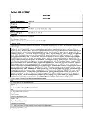
JSC-48024-114<strong>EVA</strong> <strong>Checklist</strong>STS-114 Flight SupplementMission Operations Directorate<strong>EVA</strong>, Robotics, and Crew SystemsOperations DivisionFinal, Rev AAugust 19, 2004NOTEThis supplement is to be integrated into the generic editionto provide a complete document for the specific flight.Some pages in the generic edition may be replaced withsupplemental pages identified as ‘TEMP’. These genericpages, if any, must be retained for use on future flights.National Aeronautics andSpace AdministrationLyndon B. Johnson Space CenterHouston, TexasVerify this is the correct version for the pending operation (training, simulation or flight).Electronic copies of FDF books are available. URL: http://mod.jsc.nasa.gov/do3/FDF/index.html
Incorporates the following:482#: None – Establishes baselineAREAS OF TECHNICAL RESPONSIBILITYBook Manager DX32/M. Myers 281-483-7501Alternate Book Manager DX32/C. Begley 281-483-7495FS ii <strong>EVA</strong>/114/FIN A
<strong>EVA</strong> CHECKLISTSTS-114 FLIGHT SUPPLEMENTLIST OF EFFECTIVE PAGESFINAL 12/06/02REV A 08/19/04Sign Off ........................... * 114/FIN AFS ii................................. * 114/FIN Aiii...................................... * genericiv ..................................... * genericFS v................................. * 114/FIN AFS vi................................ * 114/FIN AFS vii ............................... * 114/FIN AFS viii .............................. * 114/FIN AFS ix................................ 114/FIN AFS x................................. 114/FIN AFS xi................................ 114/FIN AFS xii ............................... 114/FIN AFS xiii .............................. 114/FIN AFS xiv .............................. 114/FIN A1-1................................... generic1-2................................... generic1-3................................... generic1-4................................... generic1-5................................... generic1-6................................... generic1-7................................... generic1-8................................... generic1-9................................... generic1-10................................. generic2-1................................... generic2-2................................... generic2-3................................... generic2-4................................... generic2-5................................... generic2-6................................... generic3-1................................... generic3-2................................... generic3-3................................... generic3-4................................... generic3-5................................... generic3-6................................... generic3-7................................... generic3-8................................... genericCC 3-9............................. genericCC 3-10........................... generic3-11................................. generic3-12................................. genericTEMP FS 4-1 .................. 114/FIN ATEMP FS 4-2 .................. ALL/FIN A4-3................................... generic4-4 ................................... generic4-5 ................................... generic4-6 ................................... generic4-7 ................................... generic4-8 ................................... generic4-9 ................................... generic4-10 ................................. genericFS CC 4-11...................... 114/FIN AFS CC 4-12...................... 114/FIN A5-1 ................................... generic5-2 ................................... generic5-3 ................................... generic5-4 ................................... genericA6-1................................. genericCC A6-2........................... generic6-3 ................................... genericCC 6-4 ............................. genericFS 7-1.............................. 114/FIN AFS 7-2.............................. 114/FIN AFS 7-3.............................. 114/FIN AFS 7-4.............................. 114/FIN AFS 7-5.............................. 114/FIN AFS 7-6.............................. 114/FIN AFS 7-7.............................. 114/FIN AFS 7-8.............................. 114/FIN AFS 7-9.............................. 114/FIN AFS 7-10............................ 114/FIN AFS 7-11............................ 114/FIN AFS 7-12............................ 114/FIN AFS 7-13............................ 114/FIN AFS 7-14............................ 114/FIN AFS 7-15............................ 114/FIN AFS 7-16............................ 114/FIN AFS 7-17............................ 114/FIN AFS 7-18............................ 114/FIN AFS 7-19............................ 114/FIN AFS 7-20............................ 114/FIN AFS 7-21............................ 114/FIN AFS 7-22............................ 114/FIN AFS 7-23............................ 114/FIN AFS 7-24............................ 114/FIN AFS 7-25............................ 114/FIN AFS 7-26............................ 114/FIN AFS 7-27............................ 114/FIN AFS 7-28............................ 114/FIN A* – Omit from flight bookFS v <strong>EVA</strong>/114/FIN A
FS 7-29 ........................... 114/FIN AFS 7-30 ........................... 114/FIN AFS 7-31 ........................... 114/FIN AFS 7-32 ........................... 114/FIN AFS 7-33 ........................... 114/FIN AFS 7-34 ........................... 114/FIN AFS 7-35 ........................... 114/FIN AFS 7-36 ........................... 114/FIN A8-1................................... generic8-2................................... generic8-3................................... generic8-4................................... generic8-5................................... generic8-6................................... generic9-1................................... generic9-2................................... generic9-3................................... generic9-4................................... generic9-5................................... generic9-6................................... generic10-1................................. generic10-2................................. generic10-3................................. generic10-4................................. generic10-5................................. generic10-6................................. generic10-7................................. generic10-8................................. generic10-9................................. generic10-10............................... generic11-1................................. generic11-2................................. generic11-3................................. generic11-4................................. generic12-i .................................. generic12-ii ................................. generic12-1................................. generic12-2................................. generic12-3................................. generic12-4................................. generic12-5................................. generic12-6................................. generic12-7................................. generic12-8................................. generic12-9................................. generic12-10............................... generic12-11............................... generic12-12............................... generic12-13............................... generic12-14............................... generic12-15............................... generic12-16............................... generic12-17 ............................... generic12-18 ............................... generic13-1 ................................. generic13-2 ................................. generic13-3 ................................. generic13-4 ................................. generic14-1 ................................. generic14-2 ................................. generic14-3 ................................. generic14-4 ................................. generic14-5 ................................. generic14-6 ................................. generic14-7 ................................. generic14-8 ................................. generic14-9 ................................. generic14-10 ............................... generic14-11 ............................... generic14-12 ............................... generic14-13 ............................... generic14-14 ............................... generic14-15 ............................... generic14-16 ............................... generic14-17 ............................... generic14-18 ............................... generic14-19 ............................... generic14-20 ............................... generic14-21 ............................... generic14-22 ............................... generic15-1 ................................. generic15-2 ................................. generic15-3 ................................. generic15-4 ................................. generic15-5 ................................. generic15-6 ................................. generic15-7 ................................. generic15-8 ................................. generic15-9 ................................. generic15-10 ............................... generic15-11 ............................... generic15-12 ............................... generic15-13 ............................... generic15-14 ............................... generic16-i .................................. generic16-ii.................................. genericTEMP FS 16-1................. 114/FIN ATEMP FS 16-2................. ALL/FIN AFS 16-3............................ 114/FIN AFS 16-4............................ 114/FIN AFS 16-5............................ 114/FIN AFS 16-6............................ 114/FIN AFS 16-7............................ 114/FIN AFS 16-8............................ 114/FIN AFS vi <strong>EVA</strong>/114/FIN A
FS 16-9 ........................... 114/FIN AFS 16-10 ......................... 114/FIN AFS 16-11 ......................... 114/FIN AFS 16-12 ......................... 114/FIN AFS 16-13 ......................... 114/FIN AFS 16-14 ......................... 114/FIN AFS 16-15 ......................... 114/FIN AFS 16-16 ......................... 114/FIN AFS 16-17 ......................... 114/FIN AFS 16-18 ......................... 114/FIN AFS 16-19 ......................... 114/FIN AFS 16-20 ......................... 114/FIN A17-1................................. * generic17-2................................. * genericFS 18-1 ........................... 114/FIN AFS 18-2 ........................... 114/FIN AFS 18-3 ........................... 114/FIN AFS 18-4 ........................... 114/FIN AFS 18-5 ........................... 114/FIN AFS 18-6 ........................... 114/FIN AFS 18-7 ........................... 114/FIN AFS 18-8 ........................... 114/FIN AFS 18-9 ........................... 114/FIN AFS 18-10 ......................... 114/FIN AFS 18-11 ......................... 114/FIN AFS 18-12 ......................... 114/FIN AFS 18-13 ......................... 114/FIN AFS 18-14 ......................... 114/FIN AFS 18-15 ......................... 114/FIN AFS 18-16 ......................... 114/FIN AFS 18-17 ......................... 114/FIN AFS 18-18 ......................... 114/FIN AFS 18-19 ......................... 114/FIN AFS 18-20 ......................... 114/FIN AFS 18-21 ......................... 114/FIN AFS 18-22 ......................... 114/FIN AFS 18-23 ......................... 114/FIN AFS 18-24 ......................... 114/FIN AFS 18-25 ......................... 114/FIN AFS 18-26 ......................... 114/FIN AFS 18-27 ......................... 114/FIN AFS 18-28 ......................... 114/FIN AFS 18-29 ......................... 114/FIN AFS 18-30 ......................... 114/FIN AFS 18-31 ......................... 114/FIN AFS 18-32 ......................... 114/FIN AFS 18-33 ......................... 114/FIN AFS 18-34 ......................... 114/FIN AFS 18-35 ......................... 114/FIN AFS 18-36 ......................... 114/FIN AFS 18-37 ......................... 114/FIN AFS 18-38 ......................... 114/FIN AFS 18-39.......................... 114/FIN AFS 18-40.......................... 114/FIN AFS 18-41.......................... 114/FIN AFS 18-42.......................... 114/FIN AFS 18-43.......................... 114/FIN AFS 18-44.......................... 114/FIN AFS 18-45.......................... 114/FIN AFS 18-46.......................... 114/FIN A19-i .................................. generic19-ii.................................. generic19-1 ................................. generic19-2 ................................. generic19-3 ................................. generic19-4 ................................. generic19-5 ................................. generic19-6 ................................. generic19-7 ................................. generic19-8 ................................. generic19-9 ................................. generic19-10 ............................... generic20-1 .................................* generic20-2 .................................* generic* – Omit from flight bookFS vii <strong>EVA</strong>/114/FIN A
<strong>EVA</strong> CUE CARDSTitle Ref. Page Card No.SAFER CHECKOUT RESULTS (Front)....................... CC 3-9 genericSAFER STATUS TROUBLESHOOTING (Back) ......... CC 3-10 generic<strong>EVA</strong> PREBREATHE CUE CARD (Front)..................... FS CC 4-11 <strong>EVA</strong>-5a/114/O/B<strong>EVA</strong> PREBREATHE CUE CARD (Back) ..................... FS CC 4-12 <strong>EVA</strong>-5b/114/O/BDEPRESS/REPRESSNominal Configuration(Front)................................................................... CC A6-2 genericFAILED LEAK CHECK(Back of DEPRESS/REPRESS)............................. CC 6-4 genericFS viii <strong>EVA</strong>/114/FIN A
CONTENTSPAGE10.2 PSI CABIN ......................................................................................................... 1-1MASK PREBREATHE INITIATE ........................................................................... 1-2PREP FOR 10.2 PSI CABIN ................................................................................. 1-3CABIN DEPRESS TO 10.2 PSI............................................................................. 1-410.2 PSIA DEPRESS CHART............................................................................... 1-510.2 PSI CABIN CONFIG...................................................................................... 1-6MASK PREBREATHE TERMINATE ..................................................................... 1-610.2 PSI MAINTENANCE...................................................................................... 1-7CABIN REPRESS TO 14.7 PSI............................................................................. 1-814.7 PSI CABIN CONFIG...................................................................................... 1-9AIRLOCK CONFIG .................................................................................................... 2-1AIRLOCK PREP.................................................................................................... 2-2EMU SWAP........................................................................................................... 2-3BOOSTER FAN DEACTIVATION/REMOVAL....................................................... 2-4BOOSTER FAN INSTALLATION/ACTIVATION.................................................... 2-4<strong>EVA</strong> TOOL TRANSFER ........................................................................................ 2-4EMU REMOVAL.................................................................................................... 2-4EMU INSTALLATION............................................................................................ 2-4EMU CHECKOUT PREP....................................................................................... 2-5LTA RESTRAINT STRAP REMOVAL ................................................................... 2-6LTA RESTRAINT STRAP INSTALLATION ........................................................... 2-6CHECKOUTS............................................................................................................. 3-1EMU CHECKOUT ................................................................................................. 3-2EMU POWERUP .............................................................................................. 3-2COMM CHECK................................................................................................. 3-2PRIMARY REGULATOR/FAN/PUMP CHECK................................................. 3-3SOP CHECK..................................................................................................... 3-5BATTERY CHARGE CHECK INIT ................................................................... 3-5BATTERY CHARGE CHECK TERM ................................................................ 3-6EMU SWAP DURING CHECKOUT.................................................................. 3-6POST EMU C/O RECONFIG............................................................................ 3-7SAFER CHECKOUT ............................................................................................. 3-7SELF TEST SEQUENCE ...................................................................................... 3-8SAFER CHECKOUT RESULTS....................................................................... CC 3-9SAFER STATUS TROUBLESHOOTING ......................................................... CC 3-10REBA POWERED HARDWARE CHECKOUT ...................................................... 3-11<strong>EVA</strong> PREP ................................................................................................. TEMP FS 4-1MIDDECK PREP .................................................................................... TEMP FS 4-2<strong>EVA</strong> PREP............................................................................................. TEMP FS 4-2PREP FOR DONNING ..................................................................... TEMP FS 4-2EMU DONNING................................................................................................ 4-4EMU CHECK .................................................................................................... 4-5EMU PURGE......................................................................................................... 4-6EMU PREBREATHE ............................................................................................. 4-6SAFER DONNING............................................................................................ 4-6<strong>EVA</strong> COMM CONFIG............................................................................................ 4-8<strong>EVA</strong> COMM DECONFIG ....................................................................................... 4-8CO2 RMVL SYS DEACT....................................................................................... 4-9CO2 RMVL SYS ACT............................................................................................ 4-9<strong>EVA</strong> PREBREATHE CUE CARD ................................................................ FS CC 4-11EMU STATUS ............................................................................................................ 5-1EMU STATUS ....................................................................................................... 5-2FS ix <strong>EVA</strong>/114/FIN A
DEPRESS/REPRESS............................................................................................... A6-1DEPRESS/REPRESS (NOM A/L) .................................................................. CC A6-2FAILED LEAK CHECK............................................................................................... 6-3FAILED LEAK CHECK (5 PSI) ......................................................................... CC 6-4FAILED LEAK CHECK (14.7/10.2 PSI) ............................................................ CC 6-4TIMELINES ........................................................................................................... FS 7-1<strong>EVA</strong> 1 (TBD)..................................................................................................... FS 7-3<strong>EVA</strong> 2<strong>EVA</strong> 2 INHIBIT PAD .................................................................................... FS 7-5NOTES, CAUTIONS, AND WARNINGS ..................................................... FS 7-6<strong>EVA</strong> 2 BRIEFING CARD ............................................................................. FS 7-7<strong>EVA</strong> 2 SUMMARY TIMELINE...................................................................... FS 7-8<strong>EVA</strong> 2 TOOL CONFIG................................................................................. FS 7-9<strong>EVA</strong> 2 EGRESS/SETUP.............................................................................. FS 7-10CMG R&R (HC) ........................................................................................... FS 7-12CLEANUP/INGRESS................................................................................... FS 7-17<strong>EVA</strong> 3<strong>EVA</strong> 3 INHIBIT PAD .................................................................................... FS 7-19NOTES, CAUTIONS, AND WARNINGS ..................................................... FS 7-20<strong>EVA</strong> 3 BRIEFING CARD ............................................................................. FS 7-21<strong>EVA</strong> 3 SUMMARY TIMELINE...................................................................... FS 7-22<strong>EVA</strong> 3 TOOL CONFIG................................................................................. FS 7-23<strong>EVA</strong> 3 EGRESS/SETUP.............................................................................. FS 7-24ESPAD INSTALL (HC) ................................................................................ FS 7-25PRIMARY CABLE ROUTING ...................................................................... FS 7-28MISSE 1 AND 2 RETRI<strong>EVA</strong>L ...................................................................... FS 7-29MISSE 5 INSTALL ....................................................................................... FS 7-30SECONDARY CABLE ROUTING................................................................ FS 7-31ESP2 INSTALLATION ................................................................................. FS 7-33ESP2 FRGF REMOVE AND STOW............................................................ FS 7-35CLEANUP/INGRESS................................................................................... FS 7-36TOOLS AND STOWAGE ........................................................................................... 8-1PGT CHECKOUT .................................................................................................. 8-3760XD PGSC-PGT CONNECTION....................................................................... 8-4PROGRAM PGT SETTINGS................................................................................. 8-4DOWNLOAD/ERASE EVENT LOG....................................................................... 8-5PGT CONTINGENCIES ........................................................................................ 8-6POST <strong>EVA</strong> ................................................................................................................. 9-1POST <strong>EVA</strong>............................................................................................................. 9-2SUIT DOFFING ................................................................................................ 9-2SAFER DOFFING............................................................................................. 9-2EMU WATER RECHARGE .............................................................................. 9-3SAFER STOW .................................................................................................. 9-4SUIT DRYING/SEAL WIPE .............................................................................. 9-4OXYGEN RECHARGE VERIFICATION........................................................... 9-4WATER FILL VERIFICATION .......................................................................... 9-4EMU POWERDOWN........................................................................................ 9-5EMU MAINT/RECHARGE.......................................................................................... 10-1WATER RECHARGE ............................................................................................ 10-2EMU POWERUP .............................................................................................. 10-2WATER FILL..................................................................................................... 10-2OXYGEN RECHARGE VERIFICATION........................................................... 10-3WATER FILL VERIFICATION .......................................................................... 10-3FS x <strong>EVA</strong>/114/FIN A
EMU LiOH CHANGEOUT ..................................................................................... 10-4MIDDECK EMU BATTERY RECHARGE/LiOH REPLACEMENT......................... 10-5INITIATE ........................................................................................................... 10-5TERMINATE ..................................................................................................... 10-5IN-SUIT EMU BATTERY RECHARGE/CHARGE VERIFICATION ....................... 10-6INITIATE ........................................................................................................... 10-6TERMINATE ..................................................................................................... 10-6EMU POWERDOWN............................................................................................. 10-6HELMET LIGHT/PGT BATTERY RECHARGE ..................................................... 10-7INITIATE ........................................................................................................... 10-7TERMINATE ..................................................................................................... 10-7REBA BATTERY INSTALLATION......................................................................... 10-8EMU BATTERY REMOVAL/INSTALL................................................................... 10-8HELMET LIGHT BULB CHANGEOUT .................................................................. 10-9REBA BATTERY RECHARGE.............................................................................. 10-10INITIATE ........................................................................................................... 10-10TERMINATE ..................................................................................................... 10-10POST <strong>EVA</strong> ENTRY PREP ......................................................................................... 11-1POST <strong>EVA</strong> ENTRY PREP..................................................................................... 11-2SAFER ENTRY STOW..................................................................................... 11-2POST ISS <strong>EVA</strong> ENTRY PREP.............................................................................. 11-3SAFER ENTRY STOW..................................................................................... 11-3OFF-NOMINAL PROCEDURES..................................................................................... 12-iEMU CONTINGENCY PROCS.................................................................................. 12-1DISPLAY LOSS DURING POWER TRANSFER(WARM RESTART) ............................................................................................. 12-2VACUUM H2O RECHARGE (MANNED) .............................................................. 12-2LIOH REPLACEMENT (MANNED) ....................................................................... 12-3BATTERY REPLACEMENT (MANNED) ............................................................... 12-4WATER DUMP...................................................................................................... 12-5SCU SWAP (UNMANNED) ................................................................................... 12-6SCU SWAP (MANNED) ........................................................................................ 12-6EMU COLD RESTART (MANNED)....................................................................... 12-612.1 CHEMICAL CHECK/DECONTAMINATION ................................................ 12-7CONTAMINATION TEST ...................................................................................... 12-10SAFER BATTERY CHANGEOUT ......................................................................... 12-11BENDS TREATMENT ADAPTER (BTA) INSTALLATION (IN-SUIT).................... 12-12BTA PREP ........................................................................................................ 12-12BTA TREATMENT............................................................................................ 12-12BENDS TREATMENT ADAPTER (BTA) INSTALLATION(POST SUIT DOFFING) ...................................................................................... 12-14BTA PREP ........................................................................................................ 12-14BTA TREATMENT............................................................................................ 12-14EMU RESIZE......................................................................................................... 12-17DAP/<strong>EVA</strong> RESCUE/RETRIEVE ..................................................................................... 13-1<strong>EVA</strong> ORBITER CONFIGURATION............................................................................ 13-2<strong>EVA</strong> RESCUE/RETRIEVE ......................................................................................... 13-4ORBITER CONTINGENCY <strong>EVA</strong> .................................................................................... 14-1PAYLOAD BAY <strong>EVA</strong> NOMENCLATURE................................................................... 14-2RMS/PRLA CONTINGENCY <strong>EVA</strong> ............................................................................. 14-396 BOLT PRE-<strong>EVA</strong> TOOL CONFIG .......................................................................... 14-1396 BOLT <strong>EVA</strong> TIMELINE ........................................................................................... 14-14CAPTURE LATCH MANUAL RELEASE (ODS/PMA)................................................ 14-1996 BOLT <strong>EVA</strong> LAYOUT ............................................................................................. 14-21FS xi <strong>EVA</strong>/114/FIN A
<strong>EVA</strong> CUFF CHECKLIST (CIL) ........................................................................................ 15-1NORMAL <strong>EVA</strong> STATUS ............................................................................................ 15-2<strong>EVA</strong> COMM FREQUENCIES..................................................................................... 15-2EMU MAL INDEX....................................................................................................... 15-2DECOMPRESSION SICKNESS (DCS) ..................................................................... 15-3ABORT <strong>EVA</strong>............................................................................................................... 15-3TERMINATE <strong>EVA</strong> ...................................................................................................... 15-3SOP O2 ON ............................................................................................................... 15-4BATT AMPS HIGH..................................................................................................... 15-4BATT VDC LOW ........................................................................................................ 15-4SUIT P LOW .............................................................................................................. 15-4SUIT P HIGH.............................................................................................................. 15-5SOP P LOW ............................................................................................................... 15-5O2 USE HIGH ............................................................................................................ 15-5SUBLM PRESS.......................................................................................................... 15-5H2O GP LOW ............................................................................................................ 15-6RESRV H2O ON ........................................................................................................ 15-6NO VENT FLOW........................................................................................................ 15-6CO2............................................................................................................................ 15-6COMM FAILURE........................................................................................................ 15-7MISC MSGS............................................................................................................... 15-7AIR FLOW CONTAMINATION................................................................................... 15-7RADIATOR ACTUATOR DISCONNECT ................................................................... 15-8PLBD DRIVE CUT ..................................................................................................... 15-8DOOR DRIVE RESTRAINT ....................................................................................... 15-8DOOR DRIVE DISCONNECT.................................................................................... 15-9WINCH OPERATIONS .............................................................................................. 15-93-PT TOOL INSTALLATION ...................................................................................... 15-9CL LATCH TOOL ....................................................................................................... 15-10TOOL RESET ............................................................................................................ 15-10AIRLOCK LATCH DISCONNECT.............................................................................. 15-10HINGE DISCONNECT ............................................................................................... 15-10RMS JOINT ALIGN .................................................................................................... 15-10RMS SHOULDER BRACE RELEASE ....................................................................... 15-10MPM STOW/DEPLOY ............................................................................................... 15-10RMS TIEDOWN ......................................................................................................... 15-11RMS FLIGHT RELEASABLE GRAPPLE FIXTURE RELEASE ................................. 15-11PRLA OPEN/CLOSE ................................................................................................. 15-11KU ANTENNA STOW ................................................................................................ 15-12AIRLOCK EGRESS ................................................................................................... 15-12AIRLOCK INGRESS .................................................................................................. 15-12FLIGHT SPECIFIC REFERENCE .................................................................................. 16-iUNSCHEDULED/CONTINGENCY <strong>EVA</strong> TASKS ..................................... TEMP FS 16-1LF1 <strong>EVA</strong> FAILURE WORKAROUND CRIBSHEET....................................... FS 16-3RELEASE ROEU LATCHES .......................................................................... FS 16-10LATCH ROEU LATCHES............................................................................... FS 16-11STOW ROEU ARM ........................................................................................ FS 16-12MATE ROEU ARM ......................................................................................... FS 16-13ROEU OVERVIEW......................................................................................... FS 16-14MANUALLY OPEN/CLOSE CBM PETAL ...................................................... FS 16-15CLEAR/RESTRAIN CBM CAPTURE LATCH ................................................ FS 16-16REMOVE/REPLACE CBM CONTROLLER ASSEMBLY ............................... FS 16-17REMOVE/REPLACE MMOD CENTER COVER ............................................ FS 16-19GENERIC <strong>EVA</strong> REFERENCE ..................................................................... NOT FLOWNFS xii <strong>EVA</strong>/114/FIN A
FLIGHT SPECIFIC <strong>EVA</strong> REFERENCE .............................................................. FS 18-1STS-114 PAYLOAD BAY LAYOUT................................................................ FS 18-3ESP2 LAUNCH CONFIGURATION (TOP VIEW) .......................................... FS 18-4ESP2 LAUNCH CONFIGURATION (BOTTOM VIEW) .................................. FS 18-5ESPAD COMPONENTS................................................................................. FS 18-6ACTIVE ESPAD ............................................................................................. FS 18-7ESPAD LAUNCH BOLTS............................................................................... FS 18-8EUTAS COMPLIANT BOLTS......................................................................... FS 18-9ESPAD INSTALL............................................................................................ FS 18-10EUTAS............................................................................................................ FS 18-11ESPAD STRUT .............................................................................................. FS 18-12ESPAD STRUT DEPLOY............................................................................... FS 18-13ESPAD V-GUIDE ........................................................................................... FS 18-14ESPAD V-GUIDE CLOSEUP ......................................................................... FS 18-15ESP2 INSTALL............................................................................................... FS 18-16ESP2 POWER FROM ESP2 TO ORBITER ................................................... FS 18-17ESP2 ORBITER POWER CABLE STOWED ................................................. FS 18-18ESP2 POWER CABLES................................................................................. FS 18-19ESP2 FLIGHT CABLES ................................................................................. FS 18-20ESP2 CABLE TIES......................................................................................... FS 18-21PRIMARY POWER CABLE ROUTING .......................................................... FS 18-22SECONDARY CABLE INSTALL – PANEL A119 ........................................... FS 18-23SECONDARY CABLE ROUTING .................................................................. FS 18-24ACTIVE ESPAD HR LABELS......................................................................... FS 18-26PASSIVE ESPAD HR LABELS ...................................................................... FS 18-27HR AND WIF LAYOUT (ZENITH) .................................................................. FS 18-28HR AND WIF LAYOUT (NADIR) .................................................................... FS 18-29MISSE LOCATIONS....................................................................................... FS 18-30ESP2 FRGF.................................................................................................... FS 18-31LMC WITH CMG ............................................................................................ FS 18-32CMG NOMENCLATURE................................................................................ FS 18-33CMG LOCATION............................................................................................ FS 18-34AFT Z1 PRE-LAUNCH WITH BLANKET........................................................ FS 18-35CMG ON Z1.................................................................................................... FS 18-36CMG SHIMS AT Z1........................................................................................ FS 18-37BLANKET CLOSED ON CMG IN FSE ........................................................... FS 18-38NEW CMG WITH BLANKET .......................................................................... FS 18-39CMG IN FSE WITH MLI ................................................................................. FS 18-40CMG SHIMS ON FSE .................................................................................... FS 18-41CMG FSE WITHOUT MLI OR CMG............................................................... FS 18-42CMG SWAP IN PLB ....................................................................................... FS 18-43<strong>EVA</strong> EMERGENCY......................................................................................................... 19-iEMERGENCY PROCEDURES.................................................................................. 19-1EMERGENCY AIRLOCK REPRESS .................................................................... 19-3EMERGENCY AIRLOCK REPRESS................................................................ 19-4POST EMERGENCY AIRLOCK REPRESS..................................................... 19-4SAFER RESCUE................................................................................................... 19-5SAFER RESCUE.............................................................................................. 19-619.1 DCS TREATMENT...................................................................................... 19-7CUE CARD CONFIGURATION ................................................................................. 20-1FS xiii <strong>EVA</strong>/114/FIN A
This Page Intentionally BlankFS xiv <strong>EVA</strong>/114/FIN A
<strong>EVA</strong> PREPMIDDECK PREP........................................................................................... TEMP FS 4-2<strong>EVA</strong> PREP.................................................................................................... TEMP FS 4-2PREP FOR DONNING............................................................................. TEMP FS 4-2EMU DONNING.......................................................................................................... 4-4CHECK.............................................................................................................. 4-5EMU PURGE .................................................................................................................. 4-6EMU PREBREATHE....................................................................................................... 4-6SAFER DONNING ..................................................................................................... 4-6<strong>EVA</strong> COMM CONFIG...................................................................................................... 4-8DECONFIG................................................................................................. 4-8CO2 RMVL SYS DEACT ................................................................................................ 4-9ACT ..................................................................................................... 4-9<strong>EVA</strong> PREBREATHE CUE CARD...................................................................... FS CC 4-11<strong>EVA</strong> PREP114TEMP FS 4-1 <strong>EVA</strong>/114/FIN A
MIDDECK PREP (30 min)WARNINGPayload bay floods exceed EMU thermal limitsduring operation. If <strong>EVA</strong> crew will be operatingin vicinity of PLB floods, floods must be turnedoff now. Cooldown time may be as long as 6 hrAW18AHUT1. LTG FLOOD (four) – ON2. √<strong>EVA</strong> Bag installed in airlock3. √REBA sw – OFFIf EMU TV:4. Demate EMU TV power cable; connect ground plug5. Disconnect helmets; Velcro to lockers6. Remove Drink Bag restraint bag7. Fill Drink Bag from galley, remove gas and insert Drink Bag in restraintbag8. Install Drink Bag restraint bag in HUT and dispose of fill tool in wet trash9. Apply anti-fog (EMU Servicing Kit), wipe off:Helmets (not Fresnel lens)EV glasses, attach to comm cap10. Stow EMU Servicing Kit11. Install Helmets; lock12. Attach Cuff C/L to EMUs<strong>EVA</strong> PREP (90 min)MET / : MET / : MET / :<strong>EVA</strong> PREPPREP FOR DONNING (30 min)If internal airlock:ML31C1. √VAC VENT ISOL VLV CNTL tb – OP√NOZ HTR – ONIf external airlock:BOTH DCM2. Retrieve, position SCU; remove DCM cover3. Connect SCU to DCM, √lockedAW82B4. EV-1,EV-2 O2 vlv (two) – opMO13Q5. √ARLK H2O S/O VLV – OP (tb-OP)MD(flr)6. √EMU O2 ISOL VLV – OPML86B:C7. √cb MNC EXT ARLK HTR ZN 1,2 (two) – opL28. √O2 XOVR SYS 1,2 (two) – OPBOTH DCM9. PWR – BATTCAUTIONEMU must be on BATT pwr whenairlock power supply turned onAW18H 10. PWR/BATT CHGR EMU 1,2 MODE (two) – PWRBUS SEL (two) – MNA(MNB)DCM11. PWR – SCU12. Verify panels as shown next page114TEMP FS 4-2 <strong>EVA</strong>/ALL/FIN <strong>EVA</strong>/114/FIN A
(reduced copy)FS CC 4-11 <strong>EVA</strong>/114/FIN A
(reduced copy)FS CC 4-12 <strong>EVA</strong>/114/FIN A
TIMELINES<strong>EVA</strong> 1 (TBD) ............................................................................................................ FS 7-3<strong>EVA</strong> 2<strong>EVA</strong> 2 INHIBIT PAD............................................................................................ FS 7-5NOTES, CAUTIONS, AND WARNINGS............................................................. FS 7-6<strong>EVA</strong> 2 BRIEFING CARD..................................................................................... FS 7-7<strong>EVA</strong> 2 SUMMARY TIMELINE ............................................................................. FS 7-8<strong>EVA</strong> 2 TOOL CONFIG ........................................................................................ FS 7-9<strong>EVA</strong> 2 EGRESS/SETUP ..................................................................................... FS 7-10CMG R&R (HC)................................................................................................... FS 7-12CLEANUP/INGRESS .......................................................................................... FS 7-17<strong>EVA</strong> 3<strong>EVA</strong> 3 INHIBIT PAD............................................................................................ FS 7-19NOTES, CAUTIONS, AND WARNINGS............................................................. FS 7-20<strong>EVA</strong> 3 BRIEFING CARD..................................................................................... FS 7-21<strong>EVA</strong> 3 SUMMARY TIMELINE ............................................................................. FS 7-22<strong>EVA</strong> 3 TOOL CONFIG ........................................................................................ FS 7-23<strong>EVA</strong> 3 EGRESS/SETUP ..................................................................................... FS 7-24ESPAD INSTALL (HC)........................................................................................ FS 7-25PRIMARY CABLE ROUTING ............................................................................. FS 7-28MISSE 1 AND 2 RETRI<strong>EVA</strong>L ............................................................................. FS 7-29MISSE 5 INSTALL .............................................................................................. FS 7-30SECONDARY CABLE ROUTING ....................................................................... FS 7-31ESP2 INSTALLATION ........................................................................................ FS 7-33ESP2 FRGF REMOVE AND STOW ................................................................... FS 7-35CLEANUP/INGRESS .......................................................................................... FS 7-36TIMELINESFS 7-1 <strong>EVA</strong>/114/FIN A
TIMELINESThis Page Intentionally BlankFS 7-2 <strong>EVA</strong>/114/FIN A
<strong>EVA</strong> 1TBD<strong>EVA</strong> 1FS 7-3 <strong>EVA</strong>/114/FIN A
This Page Intentionally Blank<strong>EVA</strong> 1FS 7-4 <strong>EVA</strong>/114/FIN A
<strong>EVA</strong> 2 INHIBIT PADMCSMCC-M1. √FGB Main Engine Thruster Valves (4) – closed2. √FGB Manifold Valves (18) – closed3. √FGB MCS unpowered4. √SOYUZ manifolds (ten) closed5. √SOYUZ MCS unpoweredRCSIf EV crew < 27 ft from FRCS:IV1. √DAP: √FREE, LO ZO14,15,16 2. √RJDF F1, F2, F3, F4 MANF DRIVER (four) – OFFMCC 3. √Above RCS configOrbiter AntennasNOTEPossible loss of comm when forced LLFWD antennaIV If EV crew < 1.6 ft from S-Band antenna:A1R 1. S-BAND FM ANT – XMIT LOWER/RCVR UPPERO14,15,16 2. √MCC, lower antenna selectedIf no comm, or on MCC call:C3 3. S-BAND PM ANT – LL FWDWhen <strong>EVA</strong> crewmember at least 1.6 ft away from all S-Bandupper antennas:C3 4. S-BAND PM ANT – GPCMCC-H5. √KU-BAND Mask activeLAB WindowIV If EV crew near window, close window shutterFGB AntennasMCC-M 1. √TORU [TOPY] – Deactivate2. √TV System [TBC] – Deactivate3. √KURS P [Kurs] – Deactivate4. √KURS A [Kurs] – Deactivate5. √Sirius – DeactivateSOYUZ AntennasMCC-M 1. √KURS – DeactivateSM Antennas (MCC-M)MCC-M 1. Global Timing Sys 1 & 2 [GTS] – DeactivatePCUMCC-HNOTEPCUs may require up to 1 hr warm-upperiod before they are operational1. √PCUs (two) operational, in discharge modeOR√1 PCU operational in discharge modeOR√One solar arrays oriented at least 105 deg from velocityvectorUSOS AntennasMCC-H 1. SGANT (KU) – Mask for <strong>EVA</strong> WorksitesCMG InhibitsMCC-H 1. Verify EA Power Removal and InhibitS0:EPS:RPCM S01A D: RPC 17RPCM S01A D RPC 17√RPC Position – Op√Close Cmd – Inh2. Verify THA Power Removal and InhibitZ1:EPS:RPCM Z13B B: RPC 10RPCM Z13B B RPC 10√RPC Position – Op√Close Cmd – InhNOTE: EV crew should not go more zenith than the IEA bulkhead to avoidS-band antenna high gain keep-out zone (3.6 ft in high gain, 1.3 ftin low gain)FS 7-5<strong>EVA</strong>/114/FIN A<strong>EVA</strong> 2
<strong>EVA</strong> 2NOTES, CAUTIONS, AND WARNINGS <strong>EVA</strong> 2NOTESVerify connectors for debris, bent pins, and cablebend radiiCAUTIONAvoid inadvertent contact with:Grapple fixture shafts (have coating)Grapple fixture target pinSVS TargetsSSRMS/MBS operating cameras & lights (heatsource)MBSVDU, MCU, CRPCMs & Cameras (silverTeflon tape radiative surface)Passive UMADeployed TUS cablePMA1 MDM sunshadePMA2 TCS Reflector<strong>EVA</strong> craneAPAS hardwareDeployed MISSEs (A/L)CID SwitchesZ1 PCU Cathode PortsZ1 heat pipe radiators/coldplatesSASA – Antenna and Z-93 paint (Z1 & P6)P6 FPPS0 Radiators (silver Teflon tape)Avoid inadvertent contact with:S0 GPS Antenna (Z-93 paint)Lights (Z-93 paint)CAUTION (Cont)<strong>EVA</strong> connectors may become hot if leftuncovered. Limited handling may beneededPMA handrails may be hot. Handling mayneed to be limitedKeepout zone:<strong>EVA</strong> UHF PLBAntenna (stbd sill) Low power = 0.5ft (nominal) High power =2.3 ft above 1.3 ft sidesKeepout zone:WVS Antenna(stbd sill) – noneFor structural reasons:Avoid vigorous body motions, quickgrabs, and kickoff tether restraintsAvoid performing shaking motions(sinusoidal functions) more than fourcyclesIf any of these occur, wait 2-5 min toallow structural response to dissipateAvoid contact with ROEU power connectorsthat are below the payload bay sill. Lowimpact force or contact can cause hardwaredamageWARNINGPMA umbilical launch restraints haveexposed bolt threads (sharp)<strong>EVA</strong> connectors present a pinch hazard.Caution should be used whenmating/locking connectorsFuse tether buckles stowed in Node bagmay have sharp edgesDuring Lab window shutter operations,the EV crew must be clear of the LabwindowEV side of crew lock hatch is a potentialpinch point and snag hazard during hatchoperationsAvoid inner edges of WIF sockets due topotential sharp edgesTBD PRLA grounding wiper is a sharpedge hazardFS 7-6<strong>EVA</strong>/114/FIN A
<strong>EVA</strong> 2 BRIEFING CARDEV1 – Soichi EV2 – Steve IV – AndySSRMS: M1 – Wendy M2 – Vegas<strong>EVA</strong> Prep start MET:Start dressing at MET:____ / ____ ____ : ____ ________ / ____ ____ : ____ ____ i.e., _____ hours after wake up<strong>EVA</strong> PrepGet-up plan – Clothing and WCS usage in post-sleep period Food/Drink in A/L ?IDB fills (night before)Equipment lock activities – Overall big picturePrebreathe protocol reviewSuit donning plan – any special requests ? Boot Bladder Manipulation ?SAFER, MWS, tools, CL positions, bag stowage – any deviations from standard ?Airlock depress reviewEV/IV comm protocolSRMS/SSRMS initial position – any deviations from training ?Crib sheet review – only big ticket items (CMG rapid-safing, CIPAA gun safing)EV Crew Procedure ReviewOverall Timeline – just talk big picture, initial tether config, critical opsAny deviations from trained plan ?Any late additions from the Ground ?Any unplanned constraints ?Any get ahead tasks ?RMS operations – comm protocol/clearances – any off-nominal operations ?Specific Items to remember (clearances, tether ops, interference opportunities, photos, etc)Unplanned ActivitiesAny late requests from ISS expected ?Emergencies ReviewLost comm. – check location, show cuff C/L in WVS or bend backwardsEMU malfunctions – call it out, all get on same pageLost tools – don’t rush, don’t chase unless easy reachLost crewmember – Call Code L, IV to give location directions etc.SAFER ops remindersDCS procedures – Call Cuff <strong>Checklist</strong>, or potential Cuff <strong>Checklist</strong>Incapacitated crewmember – work slow, bring him in, safe sitePost <strong>EVA</strong>Suit doffing responsibilitiesPost <strong>EVA</strong> planAny special food/drink requests ?Make sure WCS and galley are available to EV crewAny lessons learned from prior <strong>EVA</strong>’s:FS 7-7<strong>EVA</strong>/114/FIN A
<strong>EVA</strong> 2 SUMMARY TIMELINEPET <strong>EVA</strong> 2TIME(HR : MIN)IV/SSRMS EV1 (SSRMS) EV2 (FF)00:00 ---SSRMS: APFR INGRESS <strong>EVA</strong> 2 EGRESS/SETUP (01:15) <strong>EVA</strong> 2 EGRESS/SETUP (01:15)- ■ POST DEPRESS and EGRESS (00:15) ■ POST DEPRESS and EGRESS (00:15)- ■ SETUP (01:00) ■ SETUP (01:00)--SSRMS: NODE LIGHT REMOVAL SSRMS APFR setup and ingress Node gap spanner install-- Temp stow Node Light Stanchion01:00 ---SSRMS: Z1 ACCESS (GCA) CMG shroud removal-- CMG R & R (04:15) CMG R & R (04:15)-- ■ REMOVE FAILED CMG (00:40) ■ REMOVE FAILED CMG (00:40)- Demate connectors Unbolt CMG, shims- Unbolt CMG, shims, remove from soft dock02:00 ---SSRMS: MANEUVERING TO PAYLOAD BAY ■ REMOVE NEW CMG (01:30) ■ REMOVE NEW CMG (01:30)- SSRMS translation to PLB TPS durometer test- Ballstack setup-- Temp stow failed CMG Temp stow failed CMG- Unbolt new CMG, temp stow Unbolt new CMG, temp stow-03:00 ------- ■ INSTALL FAILED CMG (01:00) ■ INSTALL FAILED CMG (01:00)- Retrieve failed CMG Retrieve failed CMG- Bolt failed CMG to FSE Bolt failed CMG to FSE04:00 --- Retrieve new CMG-SSRMS: MANEUVERING TO Z1 SSRMS translation to Z1 CMG PLB tool cleanup--- ■ INSTALL NEW CMG (00:45) ■ INSTALL NEW CMG (00:45)- Bolt new CMG to Z1 Bolt new CMG to Z1- Mate CMG connectors Mate CMG connectors05:00 ---- ■ REPLACE THERMAL SHROUD (00:20) ■ REPLACE THERMAL SHROUD (00:20)---SSRMS: NODE LIGHT STANCHION INSTALLATION CLEANUP/INGRESS (01:00) CLEANUP/INGRESS (01:00)- ■ CLEANUP (00:35) ■ CLEANUP (00:35)-SSRMS: APFR EGRESS Install node light stanchion Install node light stanchion06:00 --- SSRMS APFR cleanup- ■ INGRESS and PRE REPRESS (00:25) ■ INGRESS and PRE REPRESS (00:25)---<strong>EVA</strong> Time 6:30FS 7-8<strong>EVA</strong>/114/FIN A
<strong>EVA</strong> 2 TOOL CONFIGAIRLOCK! Fuse Tether! Spare PGT! WIF Extender w/Adj Tether! (zenith HR)! F5 Camera! Digital Camera! Crewlock <strong>EVA</strong> Bag #1 (Aft UIA D-ring)! 11/16” box end wrench! Durometer! Ball Stack! MUT EE (2)! Trash Bag! Gap Spanner (72-in) (2)! Gap Spanner (21-in)! RET (lg-sm) (2)! Adj Tether (2)! Safety Tether! AL D-ring Extender! RETCrewlock Endcone BagsStaging Bag! Connector Cleaner Tool Kit! MUT EE! Wire Tie Caddy (long and short)IV Bag! ISS Contamination Sampler (2)! Draeger Tubes (6)! Gold Salt Kit! Socket Caddy! Socket, 6-in ext! Socket, 1/2 in drive, 8-in ext! GP Caddy (2)! Thermal Mitten pairs (2)! <strong>EVA</strong> Ratchet! DCM plug! Ziplock bag w/2 towelsPMA1-WIF 02! Ballstack (on tool stanchion)Pre-<strong>EVA</strong> 2 Tool ConfigurationEV1! MWS! Right Swing Arm! PGT, RET! T-Bar w/wire ties (2)Trash Bag (sm)! Socket Caddy! Socket, 12-in ext! RAD, 2-in ext! Socket, 6-in ext! RET Tether (2)! Adj Tether (2)! BRT w/2 wire ties, RET! RET (sm/lg)! Adj Tether (2, each wrist)! Waist Tether (2)! D-ring Extenders (2)! Safety Tether (L)! Safety Tether (R)! Ingress AidEV2! MWS! Right Swing Arm! PGT w/6-in ext, RET! T-Bar w/wire tie (2)! Socket Caddy! RET Tether (2)! Adj Tether (2)! BRT w/2 wire ties, RET! Adj Tether (left wrist)! Waist Tether (2)! D-ring Extenders (2)! Safety tether (85 ft) (R)Record:Spare PGT (serial ______, bat # ______)EV1 PGT (serial ______, bat # ______)EV2 PGT (serial ______, bat # ______)RAD (serial # _______)AIRLOCK! Fuse Tether! Spare PGT! Wire Tie Caddy! F5 Camera (2)! MUT EE! Crewlock <strong>EVA</strong> Bag #1! Durometer! 11/16” box end wrench! F5 Camera! Adj Tether (2)! MUT EE (2)! Ball stack! RET tether (lg/sm) (2)PMA1-WIF 02! Ballstack (on tool stanchion)AIRLOCK TOOLBOX #1! APFRPost-<strong>EVA</strong> 2 Tool ConfigurationEV1! MWS! Right Swing Arm! PGT, RET Tether! T-Bar w/wire ties (2)! Trash Bag (sm)! Socket Caddy! Socket, 12-in ext! RAD, 2-in ext! Socket, 6-in ext! WIF Adapter, RET Tether (sm/lg)! RET Tether (sm-sm) (2)! Adj Tether (3)! BRT w/2 wire ties, RET Tether! Adj Tether (2)! Waist Tether (2)! D-ring Extenders (2)! Safety TetherEV2! MWS! Right Swing Arm! PGT w/6-in ext, RET Tether! T-Bar w/wire tie (2)! Socket Caddy! Trash Bag (sm)! RET Tether (sm-sm) (2)! Adj Tether (2)! BRT w/1 Wire Tie, RET Tether! Adj Tether (1 left wrist)! Waist Tether (2)! D-ring Extenders (2)! Safety tether (85 ft)! Safety tetherSSRMS! APFR w/WIF adapterFS 7-9<strong>EVA</strong>/114/FIN A
<strong>EVA</strong> 2 EGRESS/SETUPIV/RMS EV1 (SSRMS) EV2 (FF)1. SSRMS: APFR INGRESS (ROBOTICS FS, <strong>EVA</strong> 2)2. ISS views for Egress/Setup: PLB C, DInitial Configuration: Waist tether (L) to EV2 Safety Tether (R)POST DEPRESS (00:05)Perform POST DEPRESS (<strong>EVA</strong>, DEPRESS/REPRESS)Initial Configuration: Waist tether (L) to A/L D-ring extender.Safety Tether (R) to EV1 Waist tether (L)POST DEPRESS (00:05)Perform POST DEPRESS (<strong>EVA</strong>, DEPRESS/REPRESS)Waist TetherA/L D-Ring ExtenderWaist TetherEV1EV2D-Ring ExtenderD-Ring ExtenderSafety Tether (85 ft)Safety Tether3. ISS view for EV1 Ingress: PLB A, B4. MCC-H: perform CMG Power Inhibits5. SSRMS: NODE LIGHT REMOVAL (ROBOTICS FS, <strong>EVA</strong> 2)EGRESS (00:10)1. Open A/L thermal cover2. Egress airlock3. Check SAFER valves (down)4. Attach right safety tether to fwd external A/L D-ring, verifyhook locked5. Attach EV2 safety tether to aft external A/L D-ring, verifyhook locked6. Give EV2 GO for egressSETUP (01:00)7. Translate to SSRMS setup worksite (port Z1, via fwd A/Ltranslation path)8. Perform Safety tether swap to SSRMS, verify hook locked9. Remove A/L safety tether from EV1 D-ring extender, stowon Node HR 601310. Configure SSRMS APFR[12,PP,F,4]11. Install Ingress aid12. Ingress APFR13. Assist EV2 with Node stanchion light removal; light’s whitepaint is no touch area14. GCA SSRMS to shroud removal worksiteEGRESS (00:10)1. Hold for EV1 GO2. Release left waist tether from A/L D-ring extender3. Retrieve Crewlock bag4. Egress A/L w/Crewlock bag on BRT5. Check SAFER valves (down)6. Close hatch thermal coverSETUP (01:00)7. Verify Crewlock bag on BRT8. Translate to Z1 worksite (via aft translation path)9. Watch all SSRMS clearances at Z1 worksite as required10. Temp stow Crewlock bag on Node HR 012211. Remove box end wrench from Crewlock bag; stow onNode HR 0122 w/RET from MWS12. Remove gap spanners/trash bag from Crewlock bag; stowon MWS13. Install gap spanners in series on Node HRs 0122 (aftstandoff) and 0121 (aft standoff), adj. end towardsmiddle. Rotate buckle of gap spanner 90 degrees toensure tension load is not too great14. Remove Node light stanchion, light’s white paint is notouch area15. PGT[B6, CCW2, 30.5]-6Ext-7/16: Release stanchion bolt,11 turns, fold stanchion towards Node, tether stanchionto Node HR 0106 away from Z1 worksiteFS 7-10<strong>EVA</strong>/114/FIN A
<strong>EVA</strong> 2 EGRESS/SETUP (Cont)IV/RMS EV1 (SSRMS) EV2 (FF)SSRMS: Z1 ACCESS (ROBOTICS FS, <strong>EVA</strong> 2)15. Remove Velcro and peel back Z1 CMG thermal shroud togain access to CMG 1. Attach adj equip tether to MLI.Hand off to EV216. Perform WVS survey of failed CMG on Z1! WVS complete16. Restrain CMG thermal shroud by attaching adj equiptether to Z1 short HR 6002. Attach 2nd adj equip tetherto MLI and stbd IAPFR17. Retrieve ball stack from TS on PMA1, WIF02, stow increwlock bag. Inspect ball stack sleeve and report if thesleeve is torn; ball stack will be NO GOFS 7-11<strong>EVA</strong>/114/FIN A
CMG R&RIV/RMS EV1 (SSRMS) EV2 (FF)1. IV: Verify with MCC inhibits for CMG 1 prior to EV1 action2. MCC: Confirm CMG EA/THA Power Removal and Inhibitsfrom CMG R & R Task Data SheetREMOVE FAILED CMG (00:40)REMOVE FAILED CMG (00:40)3. SSRMS: On <strong>EVA</strong> GO, MANEUVERING TO PAYLOADBAY (ROBOTICS FS, <strong>EVA</strong> 2)1. On IV GO, demate connector:!J6 – tuck behind CMG #2 HR2. Demate connectors:!J1 !J2 !J33. Temp stow connectors (3) with wire tie to Z1 HR 60214. PGT[B7, CCW2, 30.5] –12Ext-7/16: Loosen CMG bolts (4),2 turns each, any order:!3 !4!1 !25. PGT[A6, CCW2, 10.5] –12Ext-7/16: Remove shims (2),place in trash bag, expect 10-14 turns, any order!3c !3d6. Tether to CMG HR using lg/sm RET equip tether beforeremoving last bolt7. PGT[B7, CCW2, 30.5] –12Ext-7/16: Remove CMG bolts(4), expect 9-13 turns, any order:!3 !4!1 !28. Remove CMG from soft dock. Expect 16 lb force9. Replace CMG into soft dock and remove to verify alignment10. Give SSRMS GO to translate to LMC1. Assist EV1 as required2. BRT to CMG HR3. PGT[B7, CCW2, 30.5] –6Ext-7/16: Loosen CMG bolts (2),2 turns each, any order:!5 !64. When all 6 bolts loosened, wiggle CMG5. PGT[A6, CCW2, 10.5] –6Ext-7/16: Remove shims (2),place in trash bag, expect 10-14 turns, any order!6c !6d6. Release BRT from CMG HR7. PGT[B7, CCW2, 30.5] –6Ext-7/16: Remove CMG bolts (2),expect 9-13 turns, any order:!5 !68. Assist EV1 until CMG clear of structure, verify EV1 hasgood EMU boot to APFR bootplate mate9. Perform WVS survey of CMG location after removal offailed CMG! WVS survey complete4. ISS views while in PLB: PLB A, B, no big picture needed5. Record STA-54 Hardness Check Results:Reading #Reading123REMOVE NEW CMG (01:30)REMOVE NEW CMG (01:30)10. Retrieve Crewlock bag from Node HR 0102, stow on BRT11. Translate to shuttle ODS truss, via stbd ISS12. Remove spare safety tether from Crewlock bag, attach toODS truss, verify hook locked13. Attach spare safety tether to EMU D-ring extender, verifyhook locked14. Remove A/L 85 ft safety tether from D-ring, stow on PMAstructure15. Translate to LMC, fairlead safety tether on sill16. Temp stow Crewlock bag on LMC, retrieve durometer17. Remove pip pins (2) and open test port on DTO box18. Measure TPS repair hardness (3 readings)19. Close test port, install pip pins (2)20. Stow durometer in Crewlock bagFS 7-12<strong>EVA</strong>/114/FIN A
CMG R & R (Cont)IV/RMS EV1 (SSRMS) EV2 (FF)11. Hold failed CMG on lower inboard ball stack/MUT EE12. GCA SSRMS to new CMG13. PGT[B7, CCW2, 30.5] –12Ext-7/16: Loosen CMG bolts(4), 2 turns each, any order:!3 !4 !214. PGT[A6, CCW2, 10.5] –12Ext-7/16: Remove shims (2),place in trash bag, expect 10-14 turns, any order!3c !3d15. Tether to CMG HR using lg/sm RET equip tether beforelast bolt16. PGT[B7, CCW2, 30.5] –12Ext-7/16: Remove CMG bolts(4), expect 9-13 turns, any order:!3 !4 !217. Remove CMG 3 in from soft dock. Expect 16 lb force18. Replace CMG into soft dock and remove to verifyalignment19. GCA SSRMS to temp stow location20. Hold new CMG on upper ball stack/MUT EE21. Remove tether from new CMG21. Install ball stack and MUT EE to upper outboard LMCECOM, attach lg/sm RET to LMC HR standoff, positionball stack 15 degrees to port22. Route safety tether over lower ball stack23. Install 2nd ball stack and MUT EE to lower inboard LMCECOM, attach lg/sm RET to LMC HR standoff24. Assist EV1 with CMG temp stow, attach MUT EE to CMG,attach lg hook of RET to CMG25. Open CMG FSE thermal shroud, restrain as required26. PGT[B7, CCW2, 30.5] –6Ext-7/16: Loosen CMG bolts (2),2 turns each, any order:!1 !5 !627. PGT[A6, CCW2, 10.5] –6Ext-7/16: Remove shims (2),place in trash bag, expect 10-14 turns, any order!6c !6d28. PGT[B7, CCW2, 30.5] –6Ext-7/16: Remove CMG bolts (2),expect 9-13 turns, any order:!1 !5 !6CAUTIONAvoid CMG contact with orbiter aft bulkhead WVSantenna29. GCA EV1 to avoid WVS antenna30. BRT to LMC, turn on left side, feet to sill31. Assist EV1 with CMG temp stow, attach MUT EE to CMG,attach lg hook of RET to CMG32. Release BRT, slide feet down on port side PLBINSTALL FAILED CMG (01:00)22. GCA to failed CMG23. Tether to failed CMG24. Remove failed CMG from ball stack/MUT EE after EV2releases MUT EE25. Insert CMG into FSE soft dock position on LMC, expect16 lb force26. PGT[B7, CW2, 30.5] – 12Ext-7/16: Install CMG bolts (3),2 turns each:!3 !4 !227. Remove RET tether from CMGINSTALL FAILED CMG (01:00)33. Release failed CMG RET tether from failed CMG after EV1tether to CMG34. Release CMG from MUT EE35. Route safety tether under ballstack, translate to FSE36. GCA EV1 to avoid WVS antenna37. Assist EV1 as required38. PGT[B7, CW2, 30.5] –6Ext-7/16: Install CMG bolts (3),2 turns each:!1 !5 !6FS 7-13<strong>EVA</strong>/114/FIN A
CMG R & R (Cont)IV/RMS EV1 (SSRMS) EV2 (FF)6. IV: Record Installation values:Bolt Turns TorqueCMG02 Bolt 3CMG02 Bolt 4CMG02 Bolt 5CMG02 Bolt 6CMG02 Bolt 1CMG02 Bolt 2ADJ SHIM 3AADJ SHIM 6AADJ SHIM 3BADJ SHIM 6B7. SSRMS: On <strong>EVA</strong> GO, MANEUVER TO Z1 (ROBOTICS FS,<strong>EVA</strong> 2)8. ISS views while moving to Z1: PLB A, B28. PGT[B7, CW2, 30.5] –12Ext-7/16: Torque CMG bolts (3),expect 9-13 turns to a torque stall:!3 !4 !2Report torque/turns29. PGT: Swap 12Ext-7/16 to RAD, 2Ext-7/1630. PGT[A1, CCW1, 5.5] –RAD,2Ext-7/16: Drive adjustableshim bolts bolts (2) to contact or torque stall, no pattern:!3a !3b31. GCA to new CMGReport torque/turns32. Tether to new CMG33. Give EV2 GO for ballstack release34. Retrieve new CMG (MUT EE/Ballstack w/RET remain onCMG) after EV2 releases ball stack from LMC35. Give SSRMS GO for Z1 install positionINSTALL NEW CMG (00:45)36. Hold CMG for EV2 to remove ball stack/MUT EE37. Insert CMG into soft dock position on Z1. Expect 16 lbforce38. PGT[B7, CW2, 30.5] –12Ext-7/16: Install CMG bolts (4),2 turns each:!3 !4!1 !239. Remove tether from CMG21. PGT[B7, CW2, 30.5] –6Ext-7/16: Torque CMG bolts (3),expect 9-13 turns to a torque stall:!1 !5 !6Report torque/turns22. PGT[A1, CCW1, 5.5] –6Ext-7/16: Drive adjustable shimbolts bolts (2) to contact or torque stall, no pattern:!6a !6bReport torque/turns23. Move lg/sm RET from LMC HR to ball stack on new CMG24. Release new CMG w/ball stack from LMC on EV1 GO25. Verify EV1 has good EMU boot to APFR bootplate mate26. Retrieve lower LMC ball stack/MUT EE and lg/sm RET, stowin Crewlock bag27. Stow Crewlock bag on BRT28. Survey worksite for tool inventory, retrieve sill fairleadINSTALL NEW CMG (00:45)29. Translate to PMA, retrieve A/L 85ft safety tether, attach toEMU D-ring extender, verify locked30. Remove spare safety tether from ODS truss and EMU D-ring, stow in Crewlock bag31. Translate to Z1 worksite32. Watch all SSRMS clearances at Z1 worksite as required33. Temp stow Crewlock bag on Node HR 012234. Remove Ballstack/MUT EE/RET from CMG. Temp stow35. Check for FOD in CMG receptacle before installation36. Assist EV1 with CMG soft dock37. PGT[B7, CW2, 30.5] –6Ext-7/16: Install CMG bolts (2),2 turns each:!5 !6FS 7-14<strong>EVA</strong>/114/FIN A
CMG R & R (Cont)IV/RMS EV1 (SSRMS) EV2 (FF)9. IV: Record installation valuesBolt Turns TorqueCMG05 Bolt 3CMG05 Bolt 4CMG05 Bolt 5CMG05 Bolt 6CMG05 Bolt 1CMG05 Bolt 210. IV: Give MCC-H GO for THA power-up11. If MCC-H unable, ISS crew perform VERIFYING CMGTHERMAL HOUSING ASSEMBLY (THA) CONNECTORMATE (ASSY OPS, CMG 1 On Orbit Checkout, Steps 1-2)12. IV: Give MCC-H GO for EA power-up13. If MCC-H unable, ISS crew perform VERIFYING CMGELECTRONICS ASSEMBLY (EA) CONNECTOR MATE(ASSY OPS, CMG 1 On Orbit Checkout, Step 3)14. IV: Report CMG R & R complete to MCC40. PGT[B7, CW2, 30.5] –12Ext-7/16: Torque CMG bolts (4),expect 9-13 turns to a torque stall:!3 !4!1 !2Report torque/turns41. De-configure PGT socket42. Demate connector caps (1), stow in trash bag:!J643. Mate connector:!J644. Confirm J6 complete, GO for THA power-up45. Demate connector caps (3), stow in trash bag:!J1 !J2 !J346. Mate connectors:!J1 !J2 !J347. Confirm J1, J2, J3 complete, GO for EA power-up48. Perform WVS survey of final CMG configuration! WVS survey completeREPLACE Z1 THERMAL SHROUD (00:20)49. Replace Z1 thermal shroud and attach Velcro50. Give IV CMG INSTALL COMPLETE38. PGT[B7, CW2, 30.5] –6Ext-7/16: Torque CMG bolts (2),expect 9-13 turns to a torque stall:!5 !6Report torque/turns39. Stow ball stack on PMA TS, MUT EE, and sm/lg RET inCrewlock bag40. Assist EV1 if required41. Retrieve 11/16” box end wrench from Node HR 0122REPLACE Z1 THERMAL SHROUD (00:20)42. Replace Z1 thermal shroud and attach Velcro (use box endwrench as required)FS 7-15<strong>EVA</strong>/114/FIN A
CMG R & R – TASK DATATools:EV1 (SSRMS)EV2 (FF)PGTPGT7/16 (wobble) socket-12 ext 7/16 (wobble) socket-6 extRAD<strong>EVA</strong> Fasteners:FastenerNameCMG at Z1BoltsCMG Shims(fixed, Z1)CMG Shims(fixed, FSE)CMG at FSEBoltsCMG Shims(adjustable)Node LightStanchion BoltLabelHeadSizeQtyInstallTorque(ft-lb)ReleaseTorque(ft-lb)FailureTorque(ft-lb)7/16 6 22.92 21.7 26.7 10Turns7/16 4 5.0 8.0 9.17 10.97/16 4 5.0 8.0 9.17 10.97/16 6 22.92 21.7 26.7 107/16 4 2.5 N/A 5.6 2-57/16 1 23.0 22.5 37.5 10,16.5<strong>EVA</strong> Connectors:Harness From To Conn FunctionSizeCMG J6 Failed CMG, P6 New CMG, P6 15 PWR to THACMG J1 Failed CMG, P1 New CMG, P1 15 PWR to EACMG J2 Failed CMG, P2 New CMG, P2 15 Primary Data Bus, LBGNC-1, Channel ACMG J3 Failed CMG, P3 New CMG, P3 15 Secondary Data Bus,LB GNC-1, Channel BWarnings:1. The pop-up spring on the CMG captive <strong>EVA</strong> fasteners (CMG Bolts1-6) presents a puncture hazardCautions:1. Avoid inadvertent contact with CMG2. CMG Shims must be removed within 2 hrs of CMG powerdown onZ13. Equal force should be exerted by crew in order to prevent bindingwhen removing/installing the CMG from its mounting on Z1 andthe FSE4. CMG may have oily residue around the Torque Module Assembly,avoid contact (may cause damage to other ORUs through crosscontamination)5. Avoid contact with Optical Solar Reflector Tiles on Z1 heat piperadiators at the DDCU-HP and RPDAs. These items can bedamaged by kick loadsCMG Inhibits:MCC-H1. Verify EA Power Removal and InhibitS0:EPS:RPCM S01A D: RPC 17RPCM S01A D RPC 17√RPC Position – Op√Close Cmd – Inh2. Verify THA Power Removal and InhibitZ1:EPS:RPCM Z13B B: RPC 10RPCM Z13B B RPC 10√RPC Position – Op√Close Cmd – InhFoot Restraints:Task WIF APFR SettingALL SSRMS 12, PP, F, 4FS 7-16<strong>EVA</strong>/114/FIN A
CLEANUP/INGRESSIV/RMS EV1 EV21. SSRMS: NODE LIGHT STANCHION INSTALLATION(ROBOTICS FS, <strong>EVA</strong> 2)Bolt Turns TorqueNode Light2. SSRMS: APFR EGRESS (ROBOTICS FS, <strong>EVA</strong> 2)3. IV: Record WIF # where WIF extender is stowed:ItemWIF Extender4. IV: Perform tool inventoryWIFCLEANUP (00:35)1. Assist EV2 with node light install. Position stanchion asrequired2. Egress SSRMS3. Perform tether swap to A/L tether4. Configure APFR[6, XX,L,2] to low profile5. Receive WIF extender from EV26. Stow WIF extender in WIF ____INGRESS (00:20)7. Translate to Airlock8. Perform tool inventory9. Remove spare left safety tether, stow on aft external A/LD-ring and aft A/L HR, verify locked10. After EV2 GO, remove EV2 85 ft safety tether from aftexternal A/L D-ring, attach to EV1 left waist tether11. Remove EV1 right safety tether from EMU D-ring extenderand stow on fwd A/L HR12. √Reels unlocked, retract cable slack13. Ingress A/L14. Connect SCU to DCM; check SCU locked15. Water – OFF16. Close thermal cover, attach Velcro strapCAUTIONDo not close hatch until EMU water off for 2 min17. EV Hatch – close and lock18. Go to PRE REPRESS portion of {CREWLOCKDEPRESS/REPRESS CUE CARD} (SODF: ISS <strong>EVA</strong>SYS: <strong>EVA</strong> PREP/POST)CLEANUP (00:35)1. Stow 11/16” box end wrench in Crewlock bag2. Install Node light stanchion: Release tether from HR 0106.Hand off stanchion to EV1 to posn3. PGT[B5, CW2 30.5]-6Ext-7/16: Install stanchion bolt, 11turns to a torque stall – if required: PGT[B2, CW2 30.5]-RAD-6Ext-7/16: Install stanchion bolt, 11 turns to atorque stall4. Perform WVS survey of final Node Light configuration! WVS survey complete5. Retrieve Crewlock bag from Node HR 0102INGRESS (00:20)6. Translate to Airlock7. Perform tool inventory8. Open thermal cover9. Ingress A/L10. Retrieve WIF extender from A/L, hand to EV111. Attach left waist tether to A/L D-ring extender12. Give EV1 GO for tether ops13. Connect SCU to DCM; check SCU locked14. Water – OFF15. Go to PRE REPRESS portion of {CREWLOCKDEPRESS/REPRESS CUE CARD} (SODF: ISS <strong>EVA</strong>SYS: <strong>EVA</strong> PREP/POST)FS 7-17<strong>EVA</strong>/114/FIN A
This Page Intentionally BlankFS 7-18<strong>EVA</strong>/114/FIN A
<strong>EVA</strong> 3 INHIBIT PADMCSMCC-M1. √FGB Main Engine Thruster Valves (4) – closed2. √FGB Manifold Valves (18) – closed3. √FGB MCS unpowered4. √SOYUZ manifolds (ten) closed5. √SOYUZ MCS unpoweredRCSIf EV crew < 27 ft from FRCS:IV1. √DAP: √FREE, LO ZO14,15,16 2. √RJDF F1, F2, F3, F4 MANF DRIVER (four) – OFFMCC3. √Above RCS configOrbiter AntennasIVA1RO14,15,16NOTEPossible loss of comm when forced LL FWD antennaIf EV crew < 1.6 ft from S-Band antenna:1. S-BAND FM ANT – XMIT LOWER/RCVR UPPER2. √MCC, lower antenna selectedIf no comm, or on MCC call:C3 3. S-BAND PM ANT – LL FWDWhen <strong>EVA</strong> crewmember at least 1.6 ft away from all S-Bandupper antennas:C3MCC-H4. S-BAND PM ANT – GPC5. √KU-BAND Mask activeLAB WindowIV If EV crew near window, close window shutterFGB AntennasMCC-M 1. √TORU [TOPY] – Deactivate2. √TV System [TBC] – Deactivate3. √KURS P [Kurs] – Deactivate4. √KURS A [Kurs] – Deactivate5. √Sirius – DeactivateSOYUZ AntennasMCC-M 1. √KURS – DeactivateSM Antennas (MCC-M)MCC-M 1. Global Timing Sys 1 & 2 [GTS] – DeactivatePCUMCC-HESP2 Primary PowerMCC-HESP2 Secondary PowerNOTEPCUs may require up to 1 hr warm-up periodbefore they are operational1. √PCUs (two) operational, in discharge modeOR√1 PCU operational in discharge modeOR√One solar arrays oriented at least 105 deg from velocity vector√RPCM N1RS2 B RPC 1 – Open √RPCM N1RS2 B RPC 10 – Open√RPCM N1RS2 B RPC 2 – Open √RPCM N1RS2 B RPC 11 – Open√RPCM N1RS2 B RPC 3 – Open √RPCM N1RS2 B RPC 12 – Open√RPCM N1RS2 B RPC 4 – Open √RPCM N1RS2 B RPC 13 – Open√RPCM N1RS2 B RPC 5 – Open √RPCM N1RS2 B RPC 14 – Open√RPCM N1RS2 B RPC 6 – Open √RPCM N1RS2 B RPC 15 – Open√RPCM N1RS2 B RPC 7 – Open √RPCM N1RS2 B RPC 16 – OpenMCC-H √RPCM S04B F RPC 10 – Open√RPCM S04B F RPC 11 – Open√RPCM S04B F RPC 12 – Open√RPCM S04B F RPC 13 – Open√RPCM S04B F RPC 14 – OpenNOTE: EV crew should not go more zenith than the IEA bulkhead to avoid S-band antennahigh gain keep-out zone (3.6 ft in high gain, 1.3 ft in low gain)FS 7-19<strong>EVA</strong>/114/FIN A<strong>EVA</strong> 3
<strong>EVA</strong> 3NOTES, CAUTIONS, AND WARNINGS <strong>EVA</strong> 3NOTESVerify connectors for debris, bent pins, and cablebend radii.If EV crewmember within 10 ft of lab window,window shutter must be closedCAUTIONAvoid inadvertent contact with:Grapple fixture shafts (have coating)Grapple fixture target pinSVS TargetsSSRMS/MBS operating cameras & lights (heatsource)MBSVDU, MCU, CRPCMs & Cameras (silverTeflon tape radiative surface)Passive UMADeployed TUS cablePMA1 MDM sunshadePMA2 TCS Reflector<strong>EVA</strong> craneAPAS hardwareDeployed MISSEs (A/L)CID SwitchesZ1 PCU Cathode PortsZ1 heat pipe radiators/coldplatesSASA – Antenna and Z-93 paint (Z1 & P6)P6 FPPS0 Radiators (silver Teflon tape)Avoid inadvertent contact with:S0 GPS Antenna (Z-93 paint)Lights (Z-93 paint)CAUTION (Cont)<strong>EVA</strong> connectors may become hot if leftuncovered. Limited handling may beneededPMA handrails may be hot. Handling mayneed to be limitedKeepout zone:<strong>EVA</strong> UHF PLBAntenna (stbd sill) Low power = 0.5ft (nominal) High power =2.3 ft above 1.3 ft sidesKeepout zone:WVS Antenna(stbd sill) – noneFor structural reasons:Avoid vigorous body motions, quickgrabs, and kickoff tether restraintsAvoid performing shaking motions(sinusoidal functions) more than fourcyclesIf any of these occur, wait 2-5 min toallow structural response to dissipateAvoid contact with ROEU power connectorsthat are below the payload bay sill. Lowimpact force or contact can cause hardwaredamageWARNINGPMA umbilical launch restraints haveexposed bolt threads (sharp)<strong>EVA</strong> connectors present a pinch hazard.Caution should be used whenmating/locking connectorsFuse tether buckles stowed in Node bagmay have sharp edgesDuring Lab window shutter operations,the EV crew must be clear of the LabwindowEV side of crew lock hatch is a potentialpinch point and snag hazard during hatchoperationsAvoid inner edges of WIF sockets due topotential sharp edgesTBD PRLA grounding wiper is a sharpedge hazardFS 7-20<strong>EVA</strong>/114/FIN A
<strong>EVA</strong> 3 BRIEFING CARDEV1 – Soichi EV2 – Steve IV – AndySSRMS: M1 – Wendy M2 – Vegas<strong>EVA</strong> Prep start MET:Start dressing at MET:____ / ____ ____ : ____ ________ / ____ ____ : ____ ____ i.e., _____ hours after wake up<strong>EVA</strong> PrepGet-up plan – Clothing and WCS usage in post-sleep period Food/Drink in A/L ?IDB fills (night before)Equipment lock activities – Overall big picturePrebreathe protocol reviewSuit donning plan – any special requests ? Boot Bladder Manipulation ?SAFER, MWS, tools, CL positions, bag stowage – any deviations from standard ?Airlock depress reviewEV/IV comm protocolSRMS/SSRMS initial position – any deviations from training ?Crib sheet review – only big ticket items (CMG rapid-safing, CIPAA gun safing)EV Crew Procedure ReviewOverall Timeline – just talk big picture, initial tether config, critical opsAny deviations from trained plan ?Any late additions from the Ground ?Any unplanned constraints ?Any get ahead tasks ?RMS operations – comm protocol/clearances – any off-nominal operations ?Specific Items to remember (clearances, tether ops, interference opportunities, photos, etc)Unplanned ActivitiesAny late requests from ISS expected ?Emergencies ReviewLost comm. – check location, show cuff C/L in WVS or bend backwardsEMU malfunctions – call it out, all get on same pageLost tools – don’t rush, don’t chase unless easy reachLost crewmember – Call Code L, IV to give location directions etc.SAFER ops remindersDCS procedures – Call Cuff <strong>Checklist</strong>, or potential Cuff <strong>Checklist</strong>Incapacitated crewmember – work slow, bring him in, safe sitePost <strong>EVA</strong>Suit doffing responsibilitiesPost <strong>EVA</strong> planAny special food/drink requests ?Make sure WCS and galley are available to EV crewAny lessons learned from prior <strong>EVA</strong>’s:FS 7-21<strong>EVA</strong>/114/FIN A
<strong>EVA</strong> 3 SUMMARY TIMELINEPET <strong>EVA</strong> 3TIME(HR : MIN)IV/SSRMS EV1 (FF) EV2 (SSRMS)00:00 --- SSRMS: MANEUVERING TO AIRLOCK EGRESS <strong>EVA</strong> 3 EGRESS/SETUP (00:50) <strong>EVA</strong> 3 EGRESS/SETUP (00:50)- ■ POST DEPRESS and EGRESS (00:25) ■ POST DEPRESS and EGRESS (00:25)- SSRMS: APFR RECONFIG/INGRESS ■ SETUP (00:25) ■ SETUP (00:25)---- SSRMS: MANEUVERING TO ESP2 FOR PRIMARY CABLE ROUTING (00:45) ESPAD INSTALL (01:45)01:00 --- ESPAD REMOVAL ■ ESPAD REMOVAL (00:45)---- SSRMS: MANEUVERING TO A/L TRUNNION MISSE 1 AND 2 RETRI<strong>EVA</strong>L (01:00)- FOR ESPAD INSTALL ■ ESPAD INSTALL (01:00)-02:00 --- SSRMS: MANEUVER TO APFR- EGRESS/REMOVAL- SSRMS: ESP2 GRAPPLE-- MISSE 5 INSTALL (01:00) MISSE 5 INSTALL (01:00)--03:00 ------- SECONDARY CABLE ROUTING (01:00) SECONDARY CABLE ROUTING (01:00)--04:00 ----- SSRMS: ESP2 PRE-INSTALL-- ESP2 INSTALL (00:45) ESP2 INSTALL (00:45)- ■ GCA ESP2 TO BERTHING (00:15) ■ GCA ESP2 TO BERTHING (00:15)- ■ ATTACH ESP2 TO ESPAD (00:30) ■ ATTACH ESP2 TO ESPAD (00:30)05:00 --- ■ CONNECT ESP2 POWER (00:40)-- ESP2 FRGF REMOVE AND STOW (00:40)----06:00 --- CLEANUP/INGRESS (00:30) CLEANUP/INGRESS (00:30)-- ■ INGRESS and PRE REPRESS (00:15) ■ INGRESS and PRE REPRESS (00:15)-- <strong>EVA</strong> Time 6:30FS 7-22<strong>EVA</strong>/114/FIN A
<strong>EVA</strong> 3 TOOL CONFIGAIRLOCK! Fuse Tether #2 (Fwd W-bungee)! Spare PGT! Wire Tie Caddy (with long and short)! Fuse Tether #1 (Aft UIA D-ring, aft UIAHR)! F5 Camera (2, 28mm)! Ratchet! 2-in ext! Wire tie caddy! MISSE PEC 5 on Stbd zenith bungee! RET! Adj! MISSE Clamp Assembly # 3! Adj! D-ring extender! ESP2 Power cables (2)! Adj Tether (2)! Wire Ties (4)! IV Bag! ISS Contamination Sampler (2)! Drager Tubes (6)! Gold Salt Kit! Socket Caddy! Socket, 6-in ext! Socket, 1/2 in drive, 8-in ext! GP Caddy (2)! Thermal Mitten pairs (2)! <strong>EVA</strong> Ratchet! DCM plug! Ziplock bag w/2 towelsPre-<strong>EVA</strong> 3 Tool ConfigurationEV1! MWS! Right Swing Arm! PGT w/6-in ext, RET! Trash Bag! T-Bar w/wire tie (2)! Socket Caddy! RAD! Adj Tether (2)! RET (2) (one to D-ring extender)! BRT w/wire ties (2) w/RET, adj! D-ring Extender (2)! Waist Tether (2)! Adj Tether (2) (1 each wrist)! Safety tether (85 ft)EV2! MWS! Right Swing Arm! PGT w/6-in ext, RET! T-Bar w/wire tie (2) w/RET to wire tie! Trash bag! Socket Caddy! Adj Tether (2)! RET (2)! BRT w/wire ties (2) w/RET! D-ring Extender (2)! Waist Tether (2)! Safety Tether (R)SSRMS! APFR [6,XX,L,2]! WIF AdapterAIRLOCK! Fuse Tether #2! Spare PGT! Wire Tie Caddy! Fuse Tether #1! F5 Camera (2, 28mm)! WIF Adapter! A/L trunnion thermal covers (2)! Wire Tie Caddy! PEC 1, 2! RET! D-ring extender with crew hook lockEV1! MWS! Right Swing Arm! PGT w/6-in ext, RET! T-Bar w/wire tie (2)! Round Scoop! Trash Bag! Socket Caddy! RAD! Adj Tether (2)! RET (2)! BRT w/wire ties (2) w/RET! D-ring Extender (2)! Waist Tether (2)! Adj Tether (2) (1 each wrist)Post-<strong>EVA</strong> 3 Tool ConfigurationEV2! MWS! Right Swing Arm! PGT w/6-in ext, RET! Trash Bag! T-Bar w/wire tie (2)! Socket Caddy! BRT w/wire ties (2) w/RET! RET (sm-sm) (3)! Adj Tether (2)! D-ring Extender (2)! Waist Tether (2)! Safety TetherRecord:Spare PGT (serial # _______, bat # ______)EV1 PGT (serial # ________, bat # ______)EV2 PGT (serial # ________, bat # ______)RAD (serial # _______)FS 7-23<strong>EVA</strong>/114/FIN A
<strong>EVA</strong> 3 EGRESS/SETUPIV/RMS EV1 (FF) EV2 (SSRMS)1. SSRMS: MANEUVERING TO AIRLOCK EGRESS(ROBOTICS FS, <strong>EVA</strong> 3)2. ISS views: PLB B on monitor 2, focus on ESPADPLB C on downlink, focus at A/LA/L D-Ring ExtenderD-Ring ExtenderWaist TetherEV2Safety Tether (R)Waist TetherEV1D-Ring Extender3. IV: When EV1 complete with step 5, give SSRMS GO forAPFR RECONFIG/INGRESS maneuver4. SSRMS: After <strong>EVA</strong> GO, APFR RECONFIG/INGRESS(ROBOTICS FS, <strong>EVA</strong> 3)Initial Configuration: Waist tether (L) to EV2 Safety tetherPOST DEPRESS (00:05)Perform POST DEPRESS (DEPRESS/REPRESS Cue Card)EGRESS (00:20)1. Open A/L thermal cover2. Egress airlock3. Check SAFER valves down4. Attach safety tether (85 ft) to A/L ring, verify hook locked5. Attach EV2 Safety Tether to SSRMS, verify locked6. Give EV2 GO for EV2 step 27. Receive fuse tether #1 and primary and secondary ESP2cables (2) from EV2; temp stow at A/L HR 0554Initial Configuration: Waist tether (L) to A/L D-ring extender,Safety tether (R) to EV1 Waist tether (L)POST DEPRESS (00:05)Perform POST DEPRESS (DEPRESS/REPRESS Cue Card)EGRESS (00:20)1. Hold for EV1 GO2. Release Waist tether from A/L D-ring3. Hand out fuse tether #1 and primary and secondary ESP2cables (2) to EV14. Egress A/L5. Check SAFER valves down6. Close thermal hatch5. SSRMS: After <strong>EVA</strong> GO, MANEUVERING TO ESP2 FORESPAD REMOVAL (ROBOTICS FS, <strong>EVA</strong> 3)SETUP (00:25)8. Remove A/L trunnion covers (2). Temp stow covers onfuse tether9. Retrieve ESP2 primary cable10. Translate to primary cable worksite on Node endcone,connector J602SETUP (00:25)7. Verify/configure SSRMS APFR[12,PP, F, 6]8. Ingress SSRMS9. Verify feet in APFR10. Give SSRMS GO for motion to ESPAD REMOVALFS 7-24<strong>EVA</strong>/114/FIN A
ESPAD INSTALLIV/RMS EV2 (SSRMS)1. IV: Verify orbiter ESP 2 power cable inhibitedL12U √APCU 1, 2 CONV (two) – OFF (tb-bp)√OUTPUT RLY tb (two) – bp√OUTPUT RLY (two) – OP2. ISS views: PLB B for ESPAD Removal3. SSRMS: MANEUVERING TO A/L TRUNNION FORESPAD INSTALL (ROBOTICS FS, <strong>EVA</strong> 3), confirm inposition hold prior to ESPAD soft docking4. ISS views: PLB C for ESPAD InstallStrutPip PinLaunch Bolt BLaunch Bolt A(under strut)Launch Bolt CCompliant BoltsLocking BoltESPAD REMOVAL (00:45)1. GCA SSRMS to ESP2 pwr cable2. On IV GO, demate orbiter power cable from ESP2!P1 from J13. Mate connector to dummy panel on KYA, stow cable slackon bracket! P1 to dummy panel J34. Verify ESPAD claw open5. GCA SSRMS to ESPAD6. Deploy ESPAD strut clear of launch bolt A. Remove wireties (2) and stow in trash bag. Remove pip pin from strutFSE7. PGT[B7, CCW2, 30.5] –6Ext-7/16: Release Launch Bolt A.Expect 9 turns8. Stow ESPAD strut, insert pip pin9. PGT[B7, CCW2, 30.5] –6Ext-7/16: Release EUTASprimary compliant mount lock release. Expect approx25 turns10. PGT[B7, CCW2, 30.5] –6Ext-7/16: Release Launch Bolt C.Expect 9 turns11. Tether to active ESPAD HR 8032 inboard using ret12. PGT[B7,CCW2,30.5] –6Ext-7/16: Release EUTASsecondary compliant mount lock release. Expect approx7 turns13. PGT[B7, CCW2, 30.5] –6Ext-7/16: Release Launch Bolt B.Expect 9 turns14. Remove active ESPAD from passive ESPAD. Expect toovercome 8 lb of soft dock force15. Positively control ESPAD and give GO to IV/SSRMS16. Flip ESPAD into A/L mating position17. If required, fold down MWSESPAD INSTALL (01:00)18. On SSRMS GO, soft dock ESPAD into A/L trunnion. Expectsoft dock force of 46 lb19. Hand tighten port and starboard EUTAS center bolts withhand knobs5. IV: Record final torque values:Bolt Turns TorquePort EUTASReport torque and turnsPort EUTAS lockboltStbd EUTASStbd EUTAS lockboltEUTAS Bolt20. PGT[B7, CW2, 30.5] –6Ext-7/16: Torque down port EUTASbolt to a torque stall21. PGT[B7, CW2, 30.5] –6Ext-7/16: Torque down stbdEUTAS bolt to a torque stall22. PGT[A6, CW2, 10.5] –6Ext-7/16: Lock down stbd EUTASlock bolt to a torque stallFS 7-25<strong>EVA</strong>/114/FIN A
ESPAD INSTALL (Cont)IV/RMS EV2 (SSRMS)6. SSRMS: On <strong>EVA</strong> GO, maneuver to APFREGRESS/REMOVAL (ROBOTICS FS, <strong>EVA</strong> 3)7. SSRMS: On <strong>EVA</strong> GO, CLEAR STRUCTURE and performESP2 GRAPPLE (ROBOTICS FS, <strong>EVA</strong> 3)23. PGT[A6, CW2, 10.5] –6Ext-7/16: Lock down port EUTASlock bolt to a torque stall24. Open starboard and port V guide latches25. Perform WVS survey of ESPAD! WVS survey complete26. Give SSRMS GO to APFR EGRESS/RECONFIG27. Egress APFR28. Verify A/L toolbox # 2 WIF is [6, GG]29. Tether to APFR, remove from SSRMS30. Stow APFR in A/L Toolbox # 2 WIF[6, PP, C, 12]31. Remove WIF adapter from SSRMS32. Place waist tether on A/L HR, verify hook locked33. Remove safety tether from SSRMS, attach to A/L HR,verify hook locked34. Remove waist tether from A/L HR35. Give SSRMS GO for ESP2 GRAPPLE36. Stow WIF adapter on fuse tether37. Open socket access flap on A/L FRGF thermal cover38. Deploy ESPAD strut and connect to A/L FRGF. Moveslidelocks into locked position (2)39. Close MLI flap around strut and A/L FRGF40. Open nadir V guide latchFS 7-26<strong>EVA</strong>/114/FIN A
ESPAD INSTALL – TASK DATAEstimated Task Duration:WithSSRMSWithoutSSRMSTwo EV Crew 1:45 N/ATools:EV1 (FF)EV2 (SSRMS)PGT7/16 (wobble) socket-6 extESPAD/ESP2/ ESP2<strong>EVA</strong> Fasteners:Fastener NameESPAD LaunchBoltsESPAD Comp.Bolt (primary)ESPAD Comp.Bolt (secondary)ESPAD EUTASBoltsEUTAS lockdown boltsHeadSizeQtyInstallTorque(ft-lb)ReleaseTorque(ft-lb)FailureTorque(ft-lb)Turns7/16 3 20.8 21.6 97/16 1 8.3 12.5 77/16 1 8.3 12.5 257/16 2 25.5 25.0 101.7 7.57/16 2 8.3 8.3 23.6 2.6ESPAD Claw 7/16 1 20.8 20.8 60<strong>EVA</strong> Connectors:Harness From To Conn FunctionSizeESP2 Shuttle Pwr ESP2 ICC Keel 25 ESP2 Orbiter PowerESP2 PrimaryPower CableDust Cap Node J602 21 ESP2 Prime PowerFoot Restraints:Task WIF APFR SettingALL SSRMS 12, PP, F, 6FS 7-27<strong>EVA</strong>/114/FIN A
PRIMARY CABLE ROUTINGIV/RMS EV1 (FF)1. IV: Verify with MCC-H ISS ESP2 power inhibits in placeper <strong>EVA</strong> Inhibit padESP2 ISS power, primary and secondary inhibitsPRIMARY CABLE ROUTING (00:30)1. Translate to Node J6022. Remove dust covers, stow in trash bag! P602 (ESP2 cable) ! J602 (Node)3. On IV GO, mate connector:!ESP2 P602 to Node J6024. Wire tie J602 pig tail as required, route primary cableusing wire ties as required! Node 0134 ! Node 0135 ! A/L 05195. Temp stow cable bundle on A/L 0531ESP2 Primary CablePRIMARY CABLE ROUTING – TASK DATATools:EV1 (FF)Wire tiesTrash Bag<strong>EVA</strong> Connectors:Harness From To Conn FunctionSizeESP2 P602 Dust Cap Node J602 PowerESP2 J602 Dust Cap Node HR (wire tie) Future UseFS 7-28<strong>EVA</strong>/114/FIN A
MISSE 1 AND 2 RETRI<strong>EVA</strong>LIV/RMS EV1 (FF)MISSE #1 RETRIEVE1. Translate to MISSE #1 on ONTO #2 (equipment locknadir)2. Provide WVS survey of MISSE #13. Release pip pins (2) securing MISSE #1 open4. Close MISSE #1; reinsert pip pins (2) to secure MISSE #1closed5. Tether to MISSE #16. Release probe pip pins (2) on handrail clamp7. Remove MISSE #1 from HR clamp8. Translate to airlock hatch; temp stowMISSE #2 RETRIEVE9. Translate to MISSE #2 on C-Lk endcone10. Provide WVS survey of MISSE #211. Release pip pins (2) securing MISSE #2 open12. Close MISSE #2; reinsert pip pins (2) to secure MISSE #2closed13. Tether to MISSE #214. Release probe pip pins (2) on handrail clamp15. Remove MISSE #2 from HR clamp16. Translate to airlock, open thermal cover17. Stow MISSE (2) in A/LMISSE 1 AND 2 RETRI<strong>EVA</strong>L – TASK DATA<strong>EVA</strong> Fasteners (contingency bolts only):Fastener Name HeadSizeQty InstallTorque(ft-lb)MISSE StemContingency BoltReleaseTorque(ft-lb)FailureTorque(ft-lb)Turns7/16 2 1.7 2.1 6.0 16FS 7-29<strong>EVA</strong>/114/FIN A
MISSE 5 INSTALLIV/RMS EV1 (FF) EV2 (FF)MISSE CLAMP ASSEMBLYMISSE #5 INSTALL1. Retrieve MISSE clamp assembly #3 from A/L, hand to EV22. Retrieve MISSE 53. Place MISSE 5 in BRT4. Egress A/L, close thermal cover5. Retrieve safety tether from A/L ring6. Translate to P6 handrail 53127. Perform safety tether swap8. Attach extra safety tether to HR 5312 and right D-ringextender; verify both hooks locked9. Temp stow airlock safety tether on HR 531210. Translate to P6 aft trunnion HR 538911. Install MISSE #5 into handrail clamp pointer; checkalignment12. Insert probe pip pins (2)13. Release pip pins (2) securing MISSE #5 closed14. Open MISSE #5; reinsert pip pins (2) to secure MISSE open15. Install grounding strap into handrail standoff16. Release antenna Velcro restraints; deploy antennas17. Verify electronics switch – OFF18. Swap MISSE safe and arm plugs19. Move electronics switch to ON20. Provide WVS survey of MISSE #5 and clamp assy21. Translate to P6 handrail 531222. Perform safety tether swap to airlock safety tether; verifyhook locked23. Remove spare safety tether from HR24. Translate to joint airlock; stow spare safety tetherMISSE #5 INSTALL1. Translate to A/L2. Retrieve safety tether from A/L ring3. Receive MISSE clamp assembly #34. Stow clamp and safety tether on MWS5. Translate to P6 handrail 53096. Perform safety tether swap7. Attach extra safety tether to HR 5309 and right D-ringextender; verify both hooks locked8. Temp stow airlock safety tether on HR 53099. Translate to P6 aft trunnion HR 538910. Verify clamp assy handle in UNLOCK11. Release capture plate (1 pip pin); open12. Install clamp pointer around HR 538913. Verify capture plate pip pin installed14. Push LEVER LOCK; place clamp assy lever to LOCK15. Pull MISSE probe latching pip pins (2)16. Assist EV1 w/MISSE deploy17. Translate to P6 handrail 530918. Perform safety tether swap onto airlock safety tether; verfiyhook locked19. Remove spare safety tether from HR20. Translate to joint airlock; stow spare safety tetherMISSE 5 INSTALL – TASK DATA<strong>EVA</strong> Fasteners (contingency bolts only):Fastener Name HeadSizeQty InstallTorque(ft-lb)MISSE Stemcontingency BoltsReleaseTorque(ft-lb)FailureTorque(ft-lb)7/16 2 1.7 2.1 6.0 16TurnsFS 7-30<strong>EVA</strong>/114/FIN A
SECONDARY CABLE ROUTINGIV/RMS EV1 (FF) EV2 (FF)SECONDARY CABLE ROUTING (01:00)1. Translate to S0 face 1, bay 3 (stbd)2. Uncouple CETA cart from MT3. Reposition CETA carts for bay 3 ingress, set brake4. Enter bay 3, BRT to HR 34215. Receive pigtail cable from EV2; temp stow6. Verify enough slack for connector operations, give EV2GO for cable routing7. Release TA clamps on P59 and P57 if required8. Remove dust caps from ESP2 cable P57A and J57A andstow in trash bag9. On IV GO, demate connector:! S0 P57 from S0 panel J6410. Mate connectors:! ESP2 J57A to S0 P57! ESP2 P57A to S0 panel J6411. Restow P59 and P57 in TA clamps if required12. Restrain remaining slack and perform WVS closeout! WVS survey complete13. Egress bay and replace CETA carts. Confirm brakesreleased14. Assist EV2 as required, watch for helmet and PLSSclearance, stay stbd on CETA spurSECONDARY CABLE ROUTING (01:00)1. Retrieve wire tie caddy from fuse tether2. Retrieve secondary power cable bundle from A/L3. Fair lead at A/L end of CETA spur, stay port on CETA spur4. Translate to S0 face 6, bay 3, near HR 34235. Feed cable with pigtail end to EV16. Route secondary power cable. Restrain with wire ties asrequired! Keel strut HR (stbd end)! S0 3437 (stbd end)! MTS strut very short HR (stbd end)! MTS strut long HR (stbd end)! MTS strut short HR (port end)! Very short HR on Lab at port end of MTS strut! Lab 0215 (zenith end)! A/L 0519 (zenith end)7. Temp stow remaining cable at A/L HR 0519S0 Panel J64FS 7-31<strong>EVA</strong>/114/FIN A
SECONDARY CABLE ROUTING – TASK DATAWith WithoutSSRMS SSRMSTwo EV Crew N/A 1:00Tools:EV1 (FF)Wire tiesTrash BagEV2 (FF)Wire tiesS0 CablePre LF-1<strong>EVA</strong> Fasteners:<strong>EVA</strong> Connectors:Harness From To Conn FunctionSizeESP2 P57A Dust Cap S0 panel J64 15 PowerESP2 J57A Dust Cap S0 P57 15 PowerS0 P59 S0 J59 S0 panel J65 15 PowerS0 P57 S0 panel J57 ESP2 J57A 15 PowerP57J64Foot Restraints:Task WIF APFR SettingS0 connector mates (if required) S0- 12, YY, G, 12S0 CablePost LF-1P57J57AESP2 CableP57AJ64FS 7-32<strong>EVA</strong>/114/FIN A
ESP2 INSTALLATIONIV/RMS EV1 (FF) EV2 (FF)1. SSRMS: When 10 min from ESP2 PRE-INSTALL, give<strong>EVA</strong> a ten-min warning2. ISS views: PLB C for ESP2 Install3. SSRMS: Give IV GO to close capture claw to capture barcontact4. IV: Record number of turns: _______5. IV: Give SSRMS GO for limp mode after capture clawcontact and EV1 and EV2 verifications6. SSRMS: On IV GO, go to limp mode, give IV GO for finalcapture claw close, remind EV1 to stop if SSRMS callsbrakes on7. Comm protocol: EV1 “Comm check”; “IV GO”; “M1 GO”8. IV: Record number of turns: ________9. SSRMS: On IV GO, apply brakes, give IV GO for guidevanes10. Give EV GO for guide vanes11. IV: Record final torque values: _______12. Record number of turns: _______13. IV: Give SSRMS GO for ESP2 ungrapple whentorque/turn values are recordedBolt Turns TorqueStbd Guide VanePort Guide VaneNadir Guide VaneGCA ESP2 BERTHING (00:15)1. Translate to A/L HR 0502 location for ESP2 berthing (stbdnadir of the ESPAD)2. Confirm in position and safety tethers clear, verify ESPADclaw and latches open3. Provide GCA to SSRMS, verify nadir RTL indicatorsATTACH ESP2 TO ESPAD (00:30)4. BRT to A/L HR 05035. PGT[B7, CW2, 30.5] –6Ext-7/16: On IV GO, closecapture claw to contact, inform IV GO for limp modeReport Turns6. Verify ESP2 still within V-guides7. PGT[A3, CW1, 30.5] –6Ext-7/16: On SSRMS GO, closecapture claw to hard stop, using pulses of 1.5 turns andverify comm after each pulse (EV1 “Comm check”, “IVGO”, “M1 GO”)Report Turns8. Give IV GO for brakes9. On IV GO, manually close nadir guide vane lock down bar10. PGT[B7, CW2, 30.5] –6Ext-7/16: Torque down nadirguide vane lock down bar to a hard stop, lock knobReport Torque and Turns11. PGT[B1, CCW2, 30.5] –6Ext-7/16: After EV2 GO, backoff ESPAD capture claw 30 turnsReport Turns12. Perform WVS survey of ESPAD/ESP2! WVS survey completeGCA ESP2 BERTHING (00:15)1. Translate to MT strut HR location for ESP2 berthing(ESPAD port zenith, on Lab)2. Confirm in position and safety tethers clear, verify ESPADclaw and latches open3. Provide GCA to SSRMS, verify port and stbd RTL indicators(2)ATTACH ESP2 TO ESPAD (00:30)4. Verify ESP2 still within V-guides5. On IV GO, manually close port guide vane lock down bar6. Manually close starboard guide vane lock down bar7. PGT[B7, CW2, 30.5] –6Ext-7/16: Torque starboard guidevane lock down bar to a hard stop, lock knobReport Torque and Turns8. PGT[B7, CW2, 30.5] –6Ext-7/16: Torque port guide vanelock down bar to a hard stop, lock knob9. Give EV1 GO for claw opsCONNECT ESP2 POWER10. Retrieve and route primary and secondary ESP2 cables (2)to ESPAD HR11. Remove dust covers! P1 (Pri Cable) !P2 (Sec Cable) !J2 (ESP2)12. Mate connectors:! P1 (Cable) to J1 (ESP2)! P2 (Cable) to J2 (ESP2)13. Perform WVS closeout of connectors! WVS survey complete14. Cleanup, coil remaining cable at HR 803215. Retrieve adj tethers, stow on fuse tether16. Give IV GO for ESP2 powerFS 7-33<strong>EVA</strong>/114/FIN A
ESP2 INSTALLATION – TASK DATAEstimated Task Duration:WithSSRMSTwo EV Crew 0:45 N/ATools:EV1 (FF)WithoutSSRMSEV2 (FF)PGTPGT7/16 (wobble) socket-6 ext 7/16 (wobble) socket-6 extWire tiesWire ties<strong>EVA</strong> Fasteners:FastenerNameHeadSizeQtyInstallTorque(ft-lb)FailureTorque(ft-lb)TurnsESPAD Lock 7/16 3 25.0 N/Adown boltsESPAD Claw 7/16 1 10.0 10<strong>EVA</strong> Connectors:Harness From To Conn FunctionSizeESP2 cable P1 Dust cover ESP2 J1 25 Power (prime)ESP2 cable P2 Dust cover ESP2 J2 25 Power (secondary)ESPAD ComponentsActive ESPADPassive ESPADV-Guide<strong>EVA</strong> GCA Capture IndicatorKnob LockLock Down BoltFS 7-34<strong>EVA</strong>/114/FIN A
ESP2 FRGF REMOVE AND STOWIV/RMS EV1 (FF)ESP2 FRGF REMOVE1. IV: Record number of turns RAD is used:BoltTurnsFRGF 1FRGF 2FRGF 3FRGF 41. Retrieve ratchet w/2-in ext from A/L fuse tether2. Translate to ESP2 FRGF3. BRT to ESP2 HR 80114. Ratchet: Break torque on ESP2 FRGF stbd bolts (2).Expect 10 turns5. PGT[B1, CCW2, 30.5] –RAD-2Ext-7/16: Release ESP2FRGF stbd bolts (2). Expect 12 turnsReport # of RAD turns6. BRT to ESP2 HR 80127. Tether to ESP2 FRGF8. Ratchet: Break torque on ESP2 port FRGF bolts (2)9. PGT[B1, CCW2, 30.5] –RAD-2Ext-7/16: Release ESP2FRGF port bolts (2). Expect 12 turnsReport # of RAD turns10. Temp stow ratchet on ESP2 HR11. Place FRGF in BRT12. Translate to stbd TSAESP2 FRGF STOW13. Open stbd TSA latches (4)14. Stow FRGF15. Close TSA latches (4)16. Translate to A/LESP2 FRGF REMOVE AND STOW – TASK DATA<strong>EVA</strong> Fasteners:Fastener NameHeadSizeQtyInstallTorque(ft-lb)ReleaseTorque(ft-lb)FailureTorque(ft-lb)FRGF Bolts 7/16 4 12TurnsFS 7-35<strong>EVA</strong>/114/FIN A
CLEANUP/INGRESSIV/RMS EV1 (FF) EV2 (FF)CLEANUP (00:15)1. Photo opsCLEANUP (00:15)1. Photo ops1. Perform EV1 and EV2 tool inventoryINGRESS (00:15)2. Translate to hatch3. Perform tool inventory4. Hand in fuse tether5. On EV2 GO, remove EV2 safety tether, attach to left waisttether6. Remove safety tether from A/L ring and stow on MWS7. Ingress A/L8. Connect SCU to DCM; check SCU locked9. Water – OFF10. Close thermal cover, attach Velcro strapCAUTIONDo not close hatch until EMU water off for 2 min11. EV Hatch – close and lock12. Go to PRE REPRESS portion of {CREWLOCKDEPRESS/REPRESS CUE CARD} (SODF: ISS <strong>EVA</strong>SYS: <strong>EVA</strong> PREP/POST)INGRESS (00:15)2. Translate to hatch3. Open thermal cover4. Perform tool inventory5. Ingress A/L6. Attach left waist tether to A/L D-ring7. Give EV1 GO for tether ops8. Connect SCU to DCM; check SCU locked9. Water – OFF10. Go to PRE REPRESS portion of {CREWLOCKDEPRESS/REPRESS CUE CARD} (SODF: ISS <strong>EVA</strong>SYS: <strong>EVA</strong> PREP/POST)FS 7-36<strong>EVA</strong>/114/FIN A
UNSCHEDULED/CONTINGENCY <strong>EVA</strong> TASKSLF1 <strong>EVA</strong> FAILURE WORKAROUND CRIBSHEET ................................................. FS 16-3RELEASE ROEU LATCHES ................................................................................... FS 16-10LATCH ROEU LATCHES ........................................................................................ FS 16-11STOW ROEU ARM.................................................................................................. FS 16-12MATE ROEU ARM................................................................................................... FS 16-13ROEU OVERVIEW .................................................................................................. FS 16-14MANUALLY OPEN/CLOSE CBM PETAL................................................................ FS 16-15CLEAR/RESTRAIN CBM CAPTURE LATCH.......................................................... FS 16-16REMOVE/REPLACE CBM CONTROLLER ASSEMBLY......................................... FS 16-17REMOVE/REPLACE MMOD CENTER COVER...................................................... FS 16-19UNSCH/CONT<strong>EVA</strong> TASKS114TEMP FS 16-1 <strong>EVA</strong>/114/FIN A
UNSCH/CONT<strong>EVA</strong> TASKSThis Page Intentionally Blank114TEMP FS 16-2 <strong>EVA</strong>/ALL/FIN <strong>EVA</strong>/114/FIN A
LF1 <strong>EVA</strong> FAILURE WORKAROUND CRIBSHEETProcedure Failure Work-Around Steps CommentsI. GENERIC A. TA clamps fail to release Use tether hook for additional leverage to open clampB. Connector fails to mateC. Connector pin bentDetach from soft dock and inspect, cycle disengagedconnector:! Bent pins! FOD! EMI band! Cable bend radius! Bail linkages/rivets (both passive and activeconnector sides)! Soft dock spring! O-ring seal on non-active side! Connector keying features1. Describe bent pin location to MCC! Rotate connector to bail up position, describepin condition! If possible, obtain WVS view of interface2. On MCC GO, Obtain connector pin straightener(16,21,22 gage) or needle nose pliers. Attempt pinrepairD. Connector FOD On MCC GO, obtain connector cleaner tool from A/Lstaging bag. Attempt removal of FODE. Connector EMI band bent On MCC GO, obtain needle nose pliers or forceps.Remove EMI band from connectorF. Connector bail linkage On MCC GO, re-attempt connector mate with broken bail.failureVice grips may be used for additional leverageG. Connector soft dock springbentH. Connector O-ring seal looseOn MCC GO, obtain needle nose pliers. Attempt toremove bent springMCC determine if repair isnecessary. Repair maydamage other pinsMCC determine necessity oftime to retrieve toolsMCC determine necessity oftime to retrieve toolsMCC determine potentialsafety hazards and necessityof time to retrieve toolsMCC determine necessity oftime to retrieve tools. Lowprobability of success1. Remove seal with tether hook Common occurrence2. On MCC GO, obtain needle nose pliers. Attempt toremove sealMCC determine necessity oftime to retrieve toolsFS 16-3<strong>EVA</strong>/114/FIN A
LF1 <strong>EVA</strong> FAILURE WORKAROUND CRIBSHEET (Cont)Procedure Failure Work-Around Steps CommentsI. MMOD shield fastener failsto releaseOn MCC GO,Concurrence obtained post 5Avia <strong>EVA</strong> AITWARNINGDo not touch back side of MMOD Shields orhandle any fastener fragments due to sharp edgesFastener and Shield/Tool interface must becovered to avoid potential projectilesJ. MMOD shield fastenerdoesn’t engageK. T-handle tool fails toengage shield for handling! Retrieve ISS prybar from Node Bag and RPCM MLI! Release all other fasteners on MMOD shield! Assess clearance between the MMOD shield andthe tools! If possible, rotate fastener to position tangs off ofwire (unlock)! Place MLI cover over MMOD shield and toolinterface! Insert tool under MMOD shield by failed fastenerand pry the shield away from the structure until thefastener is freed! If required, place tape over the failed fastenerUse alternate fastener(s). Two total fasteners per shieldshould be engaged. For non-overlapping shields,fasteners should be diagonally opposite. Overlappingshields should use fasteners opposite of the overlappingend1. Remove adjacent fasteners, attempt reinstallation oftool into shield2. Use only one shield tool for handling1. Verify knob in release positionL. PAD release knob fails torotate to close 2. Stow PAD, retrieve backup PAD from Node bagM. PAD release knob fails to 1. Verify knob in release positionrotate to open2. Attempt to rotate release knob using 7/16” ratchet onknob’s 7/16” hex stud3. To remove PAD from SRMS, release contingencyrelease bar by rotating 7/16” captive release bolts (2)ccwFS 16-4<strong>EVA</strong>/114/FIN A
LF1 <strong>EVA</strong> FAILURE WORKAROUND CRIBSHEET (Cont)Procedure Failure Work-Around Steps CommentsN. APFR doesn’t install in WIF 1. Verify APFR collar in install position2. Attempt APFR installation in adjacent WIF3. If APFR installs in adjacent WIF, use backup WIFO. Safety tether doesn’t tend4. If APFR doesn’t install in adjacent WIF, use alternateAPFR1. Pull out small amount of cable, allow reel to retractwhile holding cable slightly tensioned2. Use alternate safety tetherP. TSA latch failed closed Release 7/16” <strong>EVA</strong> bolt on latch bracket, rotate bracketclear of latch tongueQ. TSA latch failed open Close remaining latches (3 of 4 required for landing)II. INSTALLHANDRAILA. Handrail will not install inseat track1. Verify rigid BRT2. Verify handrail shoe is completely released3. PGT[A4 5.0ft-lb, CCW2 30RPM]-6Ext-7/16: Verifyhandrail bolt completely releasedB. Fastener will not engagecompletelyIII. ESPADINSTALLA. EUTAS compliant mountlock fastener (outboard)fails to releaseB. EUTAS compliant mountlock fastener (inboard) failsto releaseC. ESPAD Launch bolt (A, Bor C) fail to releaseRelease bolt, verify alignment, re-attempt nominalinstallation1. If less than one turn, set PGT to manual ratchet mode2. If less than one turn, use ratchet with cheater bar3. If less than one turn, do not remove from FSE1. If less than 15 turns, set PGT to manual ratchet mode2. If less than 15 turns, use ratchet with cheater bar3. If less than 15 turns, do not remove from FSE1. Increase PGT torque setting to B7, ensure lockingsleeve is fully depressed2. Contingency Release:Remove contingency bolt from pallet side of passiveESPAD PGT[B7, CC2, 30.5], expect 12 turns. Ballsocket housing remains attached to ESPADAfter installation to A/L, remove FSE housing fromESPAD. Retrieve ratchet, cheater bar (Z1 ETSD)and release 4 contingency bolts. Expect 38 ft-lband 14 CCW turnsOne turn is sufficient toachieve compliance forinstallation15 turns is sufficient to achievecompliance for installationFS 16-5<strong>EVA</strong>/114/FIN A
LF1 <strong>EVA</strong> FAILURE WORKAROUND CRIBSHEET (Cont)Procedure Failure Work-Around Steps CommentsD. Unable to mate ESPAD toA/L1. Back off and reattempt. Confirm ESPAD compliantbolts release and no jamming has occurred2. Manipulate/rotate EUTAS by hand to push overtrunnionEUTAS has 3 shear pins thatengage with mating holes inthe tip of the trunnion. EUTASis mounted on a compliantmount which allows for5 degrees of rotational freedomas well as 6 degrees of coningangle provided by the EUTASgimbal mount3. Allow 5-10 minute thermal equalization ESPAD my require thermalE. Unable to deploy strutF. Unable to engage EUTASlocking boltdwell time4. Retrieve PRDs (2) and strap down ESPAD to engageEUTAS:Stbd: PRD strap from A/L HR 0501 to ESPAD HR 8033nadir under ESPAD HR 8031 through the openingin ESPAD then back to A/L HR 0502, hook the endsof the PRD togetherPort: PRD box hook to A/L HR 0531 then strap nadir overfront of ESPAD in between 8036 and port EUTASthen nadir to hook (strap end) on A/L HR 05301. Verify both wire ties are released Wire ties installed at CEIT2. Release hinge bolt: PGT[B7, CCW2, 30.5] Expect14 ft-lb and 21 turns1. Install wire ties:ESPAD HR 8036 (port) or 8035 (stbd) attach 2 wireties together then attach to lock nutF. Unable to mate strut to A/L Adjust strut length:Open MLIDisengage two slide locks at end of adjustment handleRotate CW to extend, CCW to retractEngage locks and replace MLIG. Unable to open V-guides Loosen tie down pin: PGT[B7, CCW2, 30.5] Expect22 turns. After installation of ESP2, V-guide will beattached in reverse order: PGT[B7, CW2, 30.5] 22 turnsFS 16-6<strong>EVA</strong>/114/FIN A
LF1 <strong>EVA</strong> FAILURE WORKAROUND CRIBSHEET (Cont)Procedure Failure Work-Around Steps CommentsIV. ESP2 DEPLOY A. ESP2 PRLAs will notreleaseB. ESP2 will not release fromKYAPerform contingency override on PRLA. Refer to genericPRLA release procedure1. Close PRLAs (IV) then <strong>EVA</strong> perform:Release Lock Bolt, PGT[B5(21 ft-lb), CCW1, 30.5]8 turnsTurn shaft bolt from ENGAGE to DISENGAGE:PGT[B7(25 ft-lb), CCW1, 30.5] ¼ turnLock down Lock Bolt, PGT[B5(21 ft-lb), CW2, 30.5]8 turnsOpen PRLAsV. ESP2BERTHINGA. Unable to achieve captureenvelopeB. ESPAD claw fails to close2. Close PRLAs (IV) then <strong>EVA</strong> perform:Release Fork Bearing Release PGT[B2(13.5 ft-lb),CCW2, 30.5] 9.5 turnsOpen PRLAs, fwd aft sequence, release ESP2(SSRMS)Release fork bearing protection cover from KYAand secure fork bearing on shaft1. Back off and reattempt2. TBD other method3. Return ESP2 to PLB. <strong>EVA</strong> required to verify ESP2within capture envelope using marks on the keel yokeassembly1. If possible, close V guide latches2. GCA SSRMS to full capture3. Retrieve PRD: PRD box hook to A/L HR 0502 overcapture bar to port A/L 0534 (inside diagonal HR onESPAD 8031 and 8000)C. Unable to close V-guide latch 1. Nadir: PRD from ESPAD HR 8029 to ESPAD HR 8030Stbd: around the pin near ESPD HR 8033, box aft ofESPAD on back face, hooks togetherPort: around the pin under ESPAD HR 8032, box aft ofESPAD on aft face, hooks togetherD. Unable to close V-guidelocksD. ESPAD claw fails to open1. If J-slot lock fails to engage, torque down report toMCC1. Increase torque setting to PGT[B7(25.5), CCW2, 30.5]2. Tether to and loosen capture bar, 10 to 12 turns oneach passive ESPAD capture bar contingency releasebolt (2)Bar may or may not come freeFS 16-7<strong>EVA</strong>/114/FIN A
LF1 <strong>EVA</strong> FAILURE WORKAROUND CRIBSHEET (Cont)Procedure Failure Work-Around Steps CommentsVI. ESP2 CABLES A. Unable to reach ESP2 with 1. Reroute as requiredprimary cable2. Only secondary cable is required-no action necessaryVII. MISSEA. Unable to release PEC from 1. Remove clamp from HR, report to MCCMISSE clampVIII. VSSA NodeLight StanchionReleaseA. Unable to release Nodelight stanchionContact MCC. Light will not be temporarily removedIX. CMG Removalfrom Z1X. CMGREMOVALFROM FSEA. Unable to release fixedshim boltB. Unable to remove fixed shimC. Unable to release CMG boltD. Unable to remove CMGA. Unable to release fixedshim boltB. Unable to remove fixed shimC. Unable to release CMG boltD. Unable to remove CMG1. Increase PGT torque setting to PGT[A7(9.2 ft-lb),CCW1, 30.5]2. Increase PGT torque setting to PGT[B7(25.5 ft-lb),CCW1, 30.5]1. Remove other shims first, reattempt2. Tether shim, continue with nominal plan, remove shimafter CMG is removed3. Use bolt puller to pry shim out1. Re-tighten all bolts and attempt stuck bolt first,continue nominal plan if successful2. Set PGT to manual ratchet, contact MCC3. Use ratchet wrench with cheater bar1. Verify all bolts, connectors released2. Use bolt puller and pry CMG out, contact MCC1. Increase PGT torque setting to PGT[A7(9.2 ft-lb),CCW1, 30.5]2. Increase PGT torque setting to PGT[B7(25.5 ft-lb),CCW1, 30.5]1. Remove other shims first, reattempt2. Tether shim, continue with nominal plan, remove shimafter CMG is removed1. Re-tighten all bolts and attempt stuck bolt first,continue nominal plan if successful2. Set PGT to manual ratchet, contact MCC1. Verify all bolts released, MLI clear2. Use bolt puller and pry out CMG, contact MCCBolt may shear, causing loosehardwareInsert in Z1 stanchion maytorque out. This will cause aninterference with the FSEinstallationBolt may shear, causing loosehardwareFS 16-8<strong>EVA</strong>/114/FIN A
LF1 <strong>EVA</strong> FAILURE WORKAROUND CRIBSHEET (Cont)Procedure Failure Work-Around Steps CommentsXI. CMG INSTALLAT THE FSEA. Unable to drive CMG bolt 1. If 5 of 6 bolts complete, notify MCC and continue2. Verify alignment, release other bolts, reattempt boltfirst3. Remove CMG and verify no obstruction, reinstallXII. CMG INSTALLAT Z1XIII. Z1 THERMALSHROUDINSTALLXVIII. ESP2 FRGFREMOVEB. Unable to drive adjustableshim boltC. Unable to release ball stackfrom LMCA. Unable to drive CMG boltA. Unable to reattach shroudA. Unable to release bolt4. Contact MCC1. Increase torque setting to PGT[B7 (25.5 ft-lb), CCW1,30.5] ½ turn only, return to nominal setting2. Contact MCC, TBD temp stow1. PGT[TBD] remove contingency bolts (4) from LMC ECOM will release from LMC1. If 4 of 6 bolts complete, notify MCC and continue2. Verify alignment, release other bolts, reattempt bolt first3. Remove CMG and verify no obstruction, reinstall4. Contact MCC1. Notify MCC of condition and continue1. Ratchet collar to RCCW, apply manual torque2. Retrieve cheater bar and ratchet from Z1 ETSD,manually break torqueFS 16-9<strong>EVA</strong>/114/FIN A
RELEASE ROEU LATCHESIV1. √MPLM ROEU DEACT complete (TBD book)2. ROEU SAFINGR13L√PL BAY MECH PWR SYS 1,2 (two) – OFFA6U √RETEN LOGIC PWR SYS 1,SYS 2 (two) – OFFPL SEL – 3√LAT 1,2,3 (three) – OFF√1 tb – REL (LAT)√2 tb – bpTools reqd:Ratchet with 3-in Ext (Airlock)EVWARNINGFor release, do not close access cover until ROEU stowed.Latches may not snap back to closed posnA6UR13LA6UR13LGive EV GO to release ROEU3. VERIFY TALKBACKS√PL RETEN LAT 1 tb – REL√2 tb – bp√3 tb – REL4. DEMATE ROEUPL BAY MECH PWR SYS 1,2 (two) – ONPL RETEN LOGIC PWR SYS 1,SYS 2 (two) – ONPL RETEN LAT 2 – REL (tb-REL, 36 sec max)PL RETEN LAT 3 – OFFPL RETEN LOGIC PWR SYS 1, SYS 2 (two) – OFFPL BAY MECH PWR SYS 1,2 (two) – OFF1. On IV GO, open latch drive access cover:Break safety cord, release access cover (3/4 turn ccw)Open access cover (~120°)Manual drive to RELEASE:Rotate control lever to RELEASERotate latch drive cw (~9 ft-lb) to hard stop (~3/4 turn)Remove drive ratchet, clear worksiteWARNINGFor release, remain clear of latches during access cover closing.Latches may snap back to closed posn2. Reengage latch actuator:Rotate control lever to neutral posnClose, secure access cover (3/4 turn cw)Clear worksiteFS 16-10<strong>EVA</strong>/114/FIN A
LATCH ROEU LATCHESR13LA6UIV1. √MPLM ROEU DEACT complete (TBD book)2. MATE ROEU√PL BAY MECH PWR SYS 1,2 (two) – OFFPL RETEN LOGIC PWR SYS 1, SYS 2 (two) – ONPL RETEN PL SEL – 2PL RETEN PL LAT 2 – LAT (tb-LAT, 60 sec max)PL RETEN PL LAT 2 – OFFTools reqd:Ratchet with 3-in Ext (Airlock)EV3. ROEU SAFINGR13L PL BAY MECH PWR SYS 1,2 (two) – OFFA6UPL RETEN LOGIC PWR SYS 1, SYS 2 (two) – OFF√LAT 1,2,3 (three) – OFF√1 tb – bp√2 tb – LATGive EV GO to release ROEU4. VERIFY TALKBACKSA6U√PL RETEN LAT 1 tb – bp√2 tb – LAT√3 tb – LAT√RDY 3 tb – gray5. RELAX ROEUR13LPL BAY MECH PWR SYS 1,2 (two) – ONA6UPL RETEN LOGIC PWR SYS 1,SYS 2 (two) – ONPL RETEN LAT 1 – REL (tb-REL, 24 sec max)PL RETEN LAT 1 – OFF√2 tb – bpPL RETEN LOGIC PWR SYS 1,2 (two) – OFFR13L PL BAY MECH PWR SYS 1,2 (two) – OFF1. On IV GO, open latch drive access cover:Break safety cord, release access cover (3/4 turn ccw)Open access cover (~120°)Manual drive to LATCH:Rotate control lever to LATCHRotate latch drive ccw (~9 ft-lb) to hard stop (~3/4 turn)Remove drive ratchet, clear worksite2. Reengage latch actuator:Rotate control lever to neutral posnClose, secure access cover (3/4 turn cw)Clear worksiteFS 16-11<strong>EVA</strong>/114/FIN A
STOW ROEU ARMR13LA6UIV1. √MPLM ROEU DEACT complete (TBD book)2. RELEASE ROEU LATCHES√PL BAY MECH PWR SYS 1,2 (two) – ONPL RETEN LOGIC PWR SYS 1, SYS 2 (two) – ONPL RETEN PL SEL – 2PL RETEN PL LAT 3 – REL (tb-REL, 40 sec max)PL RETEN PL LAT 2 – OFFTools reqd:Ratchet with 3-in Ext (Airlock)EVR13LA6U3. ROEU SAFINGPL BAY MECH PWR SYS 1,2 (two) – OFFPL RETEN LOGIC PWR SYS 1, SYS 2 (two) – OFF√LAT 1,2,3 (three) – OFF√1 tb – REL√2 tb – bp√3 tb – RELA6UGive EV GO to stow ROEU4. VERIFY TALKBACKS√PL RETEN LAT 1 tb – REL√2 tb – bp√3 tb – REL1. On IV GO, open latch drive access cover:Break safety cord, release access cover (3/4 turn ccw)Open access cover (~120°)Manual drive to STOW:Rotate control lever to STOWRotate arm drive ccw (~23 ft-lb) to hard stop and pull arm inboard to verifyRemove drive ratchet2. Reengage arm actuator:Rotate control lever to neutral posnClose, secure access cover (3/4 turn cw)Clear worksiteFS 16-12<strong>EVA</strong>/114/FIN A
MATE ROEU ARMIV1. MPLM ROEU DEACT complete (TBD book)2. ROEU SAFINGR13L√PL BAY MECH PWR SYS 1,2 (two) – OFFA6U √RETEN LOGIC PWR SYS 1,SYS 2 (two) – OFFPL SEL – 2√LAT 1,2,3 (three) – OFF√1 tb – REL√2 tb – REL (bp)√3 tb – RELTools reqd:Ratchet with 3-in Ext (Airlock)<strong>EVA</strong>6UR13LA6UR13LGive EV GO to mate ROEU3. VERIFY TALKBACKS√PL RETEN LAT 1 tb – bp√2 tb – LAT√3 tb – REL4. LATCH ROEU LATCHESPL BAY MECH PWR SYS 1,2 (two) – ONPL RETEN LOGIC PWR SYS 1,SYS 2 (two) – ONPL RETEN LAT 3 – LAT (tb-LAT, 40 sec max)PL RETEN LAT 3 – OFF√RDY 3 tb – grayPL RETEN LOGIC PWR SYS 1,SYS 2 (two) – OFFPL BAY MECH PWR SYS 1,2 (two) – OFF5. RELAX ROEU (<strong>EVA</strong>)Monitor PL RETEN LAT 1 tbGive EV GO to STOW arm, halt once LAT 1 tb – REL1. On IV GO, open arm drive access cover:Break safety cord, release access cover (3/4 turn ccw)Open access cover (~120°)Manual drive to MATE:Rotate control lever to MATERatchet arm drive cw (~25 ft-lb) until “READY TO LATCH” posn indicated oninterface guideRemove drive ratchetClear worksite (for latching)2. RELAX ROEU (<strong>EVA</strong>)On IV GO, Rotate control lever to STOW:Ratchet arm drive ccw until IV receives LAT 1 tb – REL. Remove drive ratchet3. Reengage arm actuator:Rotate control lever to neutral posnClose, secure access cover (3/4 turn cw)Clear worksiteFS 16-13<strong>EVA</strong>/114/FIN A
ROEU OVERVIEWFS 16-14<strong>EVA</strong>/114/FIN A
MANUALLY OPEN/CLOSE CBM PETAL (00:30)TIME(HR:MN)00:00IV/RMS EV1 EV2CAUTIONDuring any CBM operation, avoidcontact with sealing surfaceTools reqd:PGT (or <strong>EVA</strong> ratchet) w/6-in extNOTEFor stbd, nadir, or zenith CBM, EV1 willoperate from RMS: CBM ACCESS(PDRS OPS, CONTINGENCY <strong>EVA</strong>).PETAL OPEN1. Configure/set up APFR, TS, tools as reqd; transferto worksitePETAL OPEN1. Configure/set up APFR, TS, tools as reqd; transferto worksiteFor port CBM, EV1 will operate fromAPFR, using following settings:For fwd half of CBM use WIF:NOD1/03-05, C=11:00, P=RR, R=G,Y=12:00For aft half of CBM use WIF:NOD1/03-03, C=11:00, P=QQ, R=G,Y=1:002. √Launch restraints (two) for failed petal locked(button pushed in)2. √Launch restraints (two) for failed petal locked(button pushed in)3. Disengage petal mechanism from capture latch: 3. Assist EV1 as reqdTurn innermost bolt (one going thru petal) w/PGTccw until capture latch disengaged (~6-8 turns)Turn innermost bolt cw to retighten4. While holding petal, release launch restraint 4. While holding petal, release 2nd launch restraint5. Slowly, allow petal to open 5. Slowly, allow petal to open00:20 6. Clean up worksite 6. Clean up worksite00:00 PETAL CLOSE PETAL CLOSE7. Close petal, hold 7. Close petal, hold8. Reengage launch restraint (push in button) 8. Reengage 2nd launch restraint (push in button)00:10FS 16-15<strong>EVA</strong>/114/FIN A
CLEAR/RESTRAIN CBM CAPTURE LATCH (00:30)TIME(HR:MN)00:00IV/RMS EV1 EV2CAUTIONDuring any CBM operation, avoidcontact with sealing surfaceTools reqd:Wire Tie CaddySm-sm Retract Tethers (2)Adj Equip Tethers (2)NOTEFor stbd, nadir, or zenith CBM, EV1 willoperate from RMS: CBM ACCESS(PDRS OPS, CONTINGENCY <strong>EVA</strong>).1. Configure/set up APFR, TS, tools as reqd; transferto worksite1. Configure/set up APFR, TS, tools as reqd; transferto worksiteFor port CBM, EV1 will operate fromAPFR, using following settings:For fwd half of CBM use WIF:NOD1/03-05, C=11:00, P=RR, R=G,Y=12:00For aft half of CBM use WIF:NOD1/03-03, C=11:00, P=QQ, R=G,Y=1:002. Restrain failed capture latch with wire ties, sm-sm 2. Assist EV1 as reqdretract tethers, or adj equip tethers out of contactzone of CBM ring (latch can be secured toturnbuckle or cable for center MMOD cover)00:30 3. Clean up worksite 3. Clean up worksiteFS 16-16<strong>EVA</strong>/114/FIN A
REMOVE/REPLACE CBM CONTROLLER ASSEMBLY (02:00)TIME(HR:MN)00:00IV/RMS EV1 EV2CAUTIONDuring any CBM operation, avoidcontact with sealing surfaceTools reqd:Airlock:PGTRAD6-in ext5/32-in Allen DriverSeat Track Tether Points (2)Connector ToolTSA:<strong>EVA</strong> RatchetNOTEFor stbd, nadir, or zenith CBM, EV1 willoperate from the RMS: CBM ACCESS(PDRS OPS, CONTINGENCY <strong>EVA</strong>).For Lab stbd, zenith, nadir CBM, EV1 willoperate from RMS. LAB FWD CBMACCESS (PDRS OPS, <strong>EVA</strong>CONTINGENCY).For port CBM, EV1 will operate fromAPFR, using following settings:For fwd half of CBM use WIF:NOD1/03-05, C=11:00, P=RR, R=G,Y=12:00For aft half of CBM use WIF:NOD1/03-03, C=11:00, P=QQ, R=G,Y=1:00.For Lab, port CBM, EV1 will operate fromAPFR using following settings:WIF: LAB-13, C=2, P=XX, R=F, Y=12CONTROLLER REMOVAL1. Configure/set up APFR, TS, tools as reqd; transferto worksiteCONTROLLER REMOVAL1. Configure/set up APFR, TS, tools as reqd; transferto worksiteFS 16-17<strong>EVA</strong>/114/FIN A
REMOVE/REPLACE CBM CONTROLLER ASSEMBLY (02:00) (Cont)TIMEIV/RMS EV1 EV2(HR:MN)2. Remove MMOD center cover as reqd:2. Assist EV1 as reqdREMOVE/REPLACE MMOD CENTER COVER(<strong>EVA</strong>, ISS <strong>EVA</strong> CONTINGENCIES), COVERREMOVAL, steps 1-63. Attach tether point to seat track on failed controller4. Disconnect cable connectors J1-J9 on controller(use connector tool as reqd)5. Disconnect grounding straps (two) from controllerwith <strong>EVA</strong> ratchet, 5/32-in Allen Driver6. Tether to tether point on controller7. Release fasteners (five) on controller assembly withPGT, 5/32-in Allen Driver (15 ft-lb, 7-8 turns ccw;PGT: A5,CCW2,15.5); detach from bulkhead01:00 8. Stow controller00:00 CONTROLLER REPLACE CONTROLLER REPLACE9. Install new controller; tighten fasteners (five) on 3. Assist EV1 as reqdcontroller assembly with PGT, 5/32-in Allen Driver(10 ft-lb, 7-8 turns cw, PGT: A5,CW2,10.5)10. Remove tether point11. Connect grounding straps (two) to controllerassembly with <strong>EVA</strong> ratchet, 5/32-in Allen Driver12. Mate cable connectors J1-J9 to controller (useconnector tool as reqd)13. Reinstall MMOD center cover as reqd:REMOVE/REPLACE MMOD CENTER COVER(<strong>EVA</strong>, ISS <strong>EVA</strong> CONTINGENCIES), COVERREINSTALL, steps 1-701:00 14. Clean up worksite 4. Clean up worksiteFS 16-18<strong>EVA</strong>/114/FIN A
REMOVE/REPLACE MMOD CENTER COVER (00:30)TIME(HR:MN)00:00IV/RMS EV1 EV2CAUTIONDuring any CBM operation, avoidcontact with sealing surfaceTools reqd:Airlock:Wire-tie caddySm-sm retract tethers (2)Adj equip tethers (2)TSA:Large cable cuttersVelcro/Tape caddyNOTEFor stbd, nadir, or zenith CBM, EV1 willoperate from RMS: CBM ACCESS(PDRS OPS, CONTINGENCY <strong>EVA</strong>).For port CBM, EV1 will operate fromAPFR, using following settings:For fwd half of CBM use WIF:NOD1/03-05, C=11:00, P=RR, R=G,Y=12:00For aft half of CBM use WIF:NOD1/03-03, C=11:00, P=QQ, R=G,Y=1:00COVER REMOVAL1. Configure/set up APFR, TS, tools as reqd; transferto worksite2. Attach Adj Eqp Tether to cover near cut point and atan additional location on cover3. Cut cable at pulley opening:Cut cable next to pulley using large cable cutter4. Release cover quadrant near affected area:Remove pip pins on pulleys (1 per pulley)Push pulley towards CBM ring, slide pulley towardhatch from slot; repeat for adjacent pulleyCinch tether to pull cover away from mating surfaceRemove pip pins on each end of standoff bar(2 per standoff)Rotate standoff bar towards hatch center 45 deg,unhook from receptaclesCinch tether to restrain cover for worksite accessCOVER REMOVAL1. Configure/set up APFR, TS, tools as reqd; transferto worksite2. Assist EV1 as reqdFS 16-19<strong>EVA</strong>/114/FIN A
REMOVE/REPLACE MMOD CENTER COVER (00:30) (Cont)TIMEIV/RMS EV1 EV2(HR:MN)5. Repeat step 6 as reqd for other CBM quadrants;restrain cover open with sm-sm retract tethers oradj equip tethers00:1500:00 COVER REINSTALL COVER REINSTALL6. Release/stow tethers used to restrain cover 3. Assist EV1 as reqd7. Reinstall cover quadrant:Reattach standoff bar, rotate outward 45 deg;reinstall pip pins if time permits (2 per standoff)Insert pullies (two) back into slots (two); reinstallpip pins if times permits (1 per pulley)8. Repeat step 3 as reqd for other removed CBMquadrants9. Secure cover using tethers or wire ties as reqd00:30 10. Clean up worksite 4. Clean up worksiteFS 16-20<strong>EVA</strong>/114/FIN A
FLIGHT SPECIFIC <strong>EVA</strong> REFERENCESTS-114 PAYLOAD BAY LAYOUT ........................................................................ FS 18-3ESP2 LAUNCH CONFIGURATION (TOP VIEW)................................................... FS 18-4ESP2 LAUNCH CONFIGURATION (BOTTOM VIEW)........................................... FS 18-5ESPAD COMPONENTS......................................................................................... FS 18-6ACTIVE ESPAD...................................................................................................... FS 18-7ESPAD LAUNCH BOLTS ....................................................................................... FS 18-8EUTAS COMPLIANT BOLTS ................................................................................. FS 18-9ESPAD INSTALL .................................................................................................... FS 18-10EUTAS.................................................................................................................... FS 18-11ESPAD STRUT....................................................................................................... FS 18-12ESPAD STRUT DEPLOY ....................................................................................... FS 18-13ESPAD V-GUIDE.................................................................................................... FS 18-14ESPAD V-GUIDE CLOSEUP.................................................................................. FS 18-15ESP2 INSTALL ....................................................................................................... FS 18-16ESP2 POWER FROM ESP2 TO ORBITER ........................................................... FS 18-17ESP2 ORBITER POWER CABLE STOWED.......................................................... FS 18-18ESP2 POWER CABLES......................................................................................... FS 18-19ESP2 FLIGHT CABLES.......................................................................................... FS 18-20ESP2 CABLE TIES................................................................................................. FS 18-21PRIMARY POWER CABLE ROUTING................................................................... FS 18-22SECONDARY CABLE INSTALL – PANEL A119.................................................... FS 18-23SECONDARY CABLE ROUTING........................................................................... FS 18-24ACTIVE ESPAD HR LABELS................................................................................. FS 18-26PASSIVE ESPAD HR LABELS............................................................................... FS 18-27HR AND WIF LAYOUT (ZENITH)........................................................................... FS 18-28HR AND WIF LAYOUT (NADIR)............................................................................. FS 18-29MISSE LOCATIONS ............................................................................................... FS 18-30ESP2 FRGF............................................................................................................ FS 18-31LMC WITH CMG..................................................................................................... FS 18-32CMG NOMENCLATURE ........................................................................................ FS 18-33CMG LOCATION .................................................................................................... FS 18-34AFT Z1 PRE-LAUNCH WITH BLANKET ................................................................ FS 18-35CMG ON Z1............................................................................................................ FS 18-36CMG SHIMS AT Z1 ................................................................................................ FS 18-37BLANKET CLOSED ON CMG IN FSE ................................................................... FS 18-38NEW CMG WITH BLANKET................................................................................... FS 18-39CMG IN FSE WITH MLI.......................................................................................... FS 18-40CMG SHIMS ON FSE............................................................................................. FS 18-41CMG FSE WITHOUT MLI OR CMG ....................................................................... FS 18-42CMG SWAP IN PLB................................................................................................ FS 18-43FLIGHT SPECIFIC<strong>EVA</strong> REFFS 18-1 <strong>EVA</strong>/114/FIN A
FLIGHT SPECIFIC<strong>EVA</strong> REFThis Page Intentionally BlankFS 18-2 <strong>EVA</strong>/114/FIN A
STS-114 PAYLOAD BAY LAYOUTFS 18-3 <strong>EVA</strong>/114/FIN A
ESP2 LAUNCH CONFIGURATION (TOP VIEW)VSSAStaged UCPESPADKYAFS 18-4 <strong>EVA</strong>/114/FIN A
ESP2 LAUNCH CONFIGURATION (BOTTOM VIEW)UTAFHRCKYAEmpty FRAM SiteKYAStaged UCPESPADFS 18-5 <strong>EVA</strong>/114/FIN A
ESPAD COMPONENTSActive ESPADPassive ESPADFS 18-6 <strong>EVA</strong>/114/FIN A
ACTIVE ESPAD<strong>EVA</strong> HandrailsHandrails3X Guide Vane Assy withLock Down and Ready toLatch IndicatorCompliant Mount Launch Lock Interface2X 5/8” UTAS on Compliant MountHandrailsMechanical Berthing Claw Assy<strong>EVA</strong> Deployable Strut, Interfaceswith Airlock Girth Ring3X Active FSEFS 18-7 <strong>EVA</strong>/114/FIN A
ESPAD LAUNCH BOLTSLaunch Bolt A, under strutLaunch Bolt BLaunch Bolt CFS 18-8 <strong>EVA</strong>/114/FIN A
EUTAS COMPLIANT BOLTSFS 18-9 <strong>EVA</strong>/114/FIN A
ESPAD INSTALLFS 18-10 <strong>EVA</strong>/114/FIN A
EUTASLock BoltEUTAS BoltFS 18-11 <strong>EVA</strong>/114/FIN A
ESPAD STRUTCont. ReleasePip PinFS 18-12 <strong>EVA</strong>/114/FIN A
ESPAD STRUT DEPLOYLength AdjustmentSlide LocksA/L SocketAdjustment LocksFS 18-13 <strong>EVA</strong>/114/FIN A
ESPAD V-GUIDERTL IndicatorV-guideLatch closed, should be open for berthingRTL Indicator BarFS 18-14 <strong>EVA</strong>/114/FIN A
ESPAD V-GUIDE CLOSEUPLock Down BoltKnob LockFS 18-15 <strong>EVA</strong>/114/FIN A
ESP2 INSTALLClawClaw BoltFS 18-16 <strong>EVA</strong>/114/FIN A
ESP2 POWER FROM ESP2 TO ORBITERLaunch ConfigurationLanding ConfigurationFS 18-17 <strong>EVA</strong>/114/FIN A
ESP2 ORBITER POWER CABLE STOWEDFS 18-18 <strong>EVA</strong>/114/FIN A
ESP2 POWER CABLESNode-1P602Primary Power CablePower outto PMA-3ShellHeatersISSPowerJ60244”40”8 splicesESP2-W117.1 ftP1PrimaryPower toESP-2ESP2S0 TrussISSPowerPlug to J64deadfacingconnector forfuture userJ57AP57A32”8 splices18”Secondary Power CableESP2-W244.5 ftSecondaryPower toESP-2P2FS 18-19 <strong>EVA</strong>/114/FIN A
ESP2 FLIGHT CABLESESP2 Primary ConnectorsESP2 Primary CableESP2 Secondary CableESP2 Secondary ConnectorsFS 18-20 <strong>EVA</strong>/114/FIN A
ESP2 CABLE TIES20” - 37”1.5”ReleaseTabLoop Velcro withIndicator FrameHook Velcro withIndicator FrameTetherLoopSSBuckleCrewLabelAreaCable Tie ID LabelFS 18-21 <strong>EVA</strong>/114/FIN A
PRIMARY POWER CABLE ROUTINGN1-J602FS 18-22 <strong>EVA</strong>/114/FIN A
SECONDARY CABLE INSTALL – PANEL A119P57J64Panel A119FS 18-23 <strong>EVA</strong>/114/FIN A
SECONDARY CABLE ROUTINGVery Short Lab HRMTS Strut Long HRS0 HR 3437Keel Strut HRMTS Strut Short HRLab HR 0215MTS Strut Very Short HRFS 18-24 <strong>EVA</strong>/114/FIN A
SECONDARY CABLE ROUTING (Cont)MTS Strut Short HRVery Short Lab HRLab HR 0215A/L HR 0519FS 18-25 <strong>EVA</strong>/114/FIN A
ACTIVE ESPAD HR LABELS802980308000803180338034 803580368032FS 18-26 <strong>EVA</strong>/114/FIN A
PASSIVE ESPAD HR LABELS802880278026800180248025FS 18-27 <strong>EVA</strong>/114/FIN A
HR AND WIF LAYOUT (ZENITH)FS 18-28 <strong>EVA</strong>/114/FIN A
HR AND WIF LAYOUT (NADIR)FS 18-29 <strong>EVA</strong>/114/FIN A
MISSE LOCATIONSPEC # 2PEC # 1FS 18-30 <strong>EVA</strong>/114/FIN A
ESP2 FRGFTether Point<strong>EVA</strong> BoltHandholdFS 18-31 <strong>EVA</strong>/114/FIN A
LMC WITH CMGFS 18-32 <strong>EVA</strong>/114/FIN A
CMG NOMENCLATUREFS 18-33 <strong>EVA</strong>/114/FIN A
CMG LOCATIONFS 18-34 <strong>EVA</strong>/114/FIN A
AFT Z1 PRE-LAUNCH WITH BLANKETFS 18-35 <strong>EVA</strong>/114/FIN A
CMG ON Z1FS 18-36 <strong>EVA</strong>/114/FIN A
CMG SHIMS AT Z1FS 18-37 <strong>EVA</strong>/114/FIN A
BLANKET CLOSED ON CMG IN FSEFS 18-38 <strong>EVA</strong>/114/FIN A
NEW CMG WITH BLANKETFS 18-39 <strong>EVA</strong>/114/FIN A
CMG IN FSE WITH MLIFS 18-40 <strong>EVA</strong>/114/FIN A
CMG SHIMS ON FSEFS 18-41 <strong>EVA</strong>/114/FIN A
CMG FSE WITHOUT MLI OR CMGFS 18-42 <strong>EVA</strong>/114/FIN A
CMG SWAP IN PLBNewOldFS 18-43 <strong>EVA</strong>/114/FIN A
This Page Intentionally BlankFS 18-44 <strong>EVA</strong>/114/FIN A
JSC-48024-114FINAL, REV A<strong>EVA</strong>CHECKLISTSTS114Flight Cover (trim bottom to expose tabs)