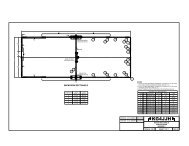
needed. Ensure that the spreaders are fully inserted into the hub and spreader clamps.Tension created from the flexed spreaders will keep the assembly secure. Repeat thisprocess for the remaining three elements, taking care to place the Driven <strong>Element</strong>feedpoint at the bottom.Carefully measure the element to element spacing on the assembly and slide the hubs asnecessary to meet the dimensions in Table 1. Assemble the boom to mast bracketbetween the Driven <strong>Element</strong> and Director-1 and adjust the position to balance theantenna. For the prototype, the center of the boom was in line with the Director-1element. Secure the hubs to the boom with the hub setscrews and mark the final hub andmounting bracket positions on the boom for future reference. Attach the coax to thefeedpoint and secure it to the mast or boom for minimum pull on the driven element.For portability, the antenna breaks down into easily transportable pieces:• 2 ea – 1 1 / 2 ”OD x 5’ boom with hubs and mounting bracket• 1 ea – 1 3 / 8 ”OD x 3’ boom connector• 16 ea – 3 / 8 ”OD spreaders (various lengths less than 4 feet long)• 4 ea – <strong>Element</strong>/Spreader clamp assembliesField DayOn the day before Field Day 2010, the antenna was assembled and hung from a treebranch at my campsite with the boom at 21 feet. An MFJ-259B antenna analyzer wasused to generate the data in Figure 2.Figure 2Although the resulting plot revealed resonance 200 KHz below the EZNEC prediction Idecided to give it the acid test and drive the antenna from a battery powered FT-817. If I<strong>6m</strong> 4-<strong>Element</strong> <strong>Quad</strong>, <strong>KG4JJH</strong> Page 4 of 5
could make contacts with 5 watts I would consider the antenna a success. Deviations inthe SWR resonance were noted when the quad was pointed toward or away from the treetrunk which was about 12 feet from the center of the antenna. I suspect that the coaxpigtail wires increased the length of the driven element and lowered resonance. If this isthe case, the driven element should be shortened to 240.375”.I took a different approach to Field Day this year. Instead of hanging around 20m wherethere was sure to be lots of activity, I chose to limit the bands to <strong>6m</strong> and 10m. I was verysurprised to see PSK activity on 10 meters and worked as many as possible. On 6 metersthe quad exhibited excellent directivity and gain. Several QSOs were completed using 5watts into New York and Canada from my campsite at Norris Dam Sate Park inTennessee. While my <strong>6m</strong> signal reports weren’t 59s I was nonetheless elated. Comparedto my 4 dBd Moxon antenna 4 , the quad has more than double the gain and appears to bequieter.SummaryThe <strong>6m</strong> 4-<strong>Element</strong> <strong>Quad</strong> is about 38% smaller in area than the <strong>6m</strong> 6-<strong>Element</strong> OWA Yagiand weighs about 16 1 / 2 pounds. Compared to the Yagi, the quad has the same gain, lessaverage F/B, and a narrower bandwidth. However, bandwidth isn’t critical for CW andSSB operation centered around 50.150 MHz. This was my first quad and I heartilyrecommend it to anyone looking to improve their 6 meter station. To aid in constructionand setup, detailed drawings are available at my website. 5Allen Baker211 Brochardt Blvd.Knoxville, TN 37934http://www.kg4jjh.comReferences1. “Route 66, 6-Meter 6-<strong>Element</strong> OWA Yagis in 9 Versions”, L.B. Cebik, W4RNL,http://cebik.com/content/a10/vhf/66.html2. Max-Gain Systems, Inc., Fiberglass Products, http://www.mgs4u.com/fiberglasstube-rod.htm3. “G0KSC SC0604Q 4el 50MHz OWA <strong>Quad</strong> <strong>Antenna</strong> with a 2.988 Metre LengthBoom”, Justin Johnson, G0KSC, http://www.g0ksc.co.uk/sc0604q.html4. “A 6 Meter Moxon”, Allen Baker, <strong>KG4JJH</strong>, QST April 2004, pp 65-69.5. “<strong>6m</strong> 4-<strong>Element</strong> <strong>Quad</strong>”, Allen Baker, <strong>KG4JJH</strong>, http://www.kg4jjh.com/quad<strong>6m</strong> 4-<strong>Element</strong> <strong>Quad</strong>, <strong>KG4JJH</strong> Page 5 of 5