
Create successful ePaper yourself
Turn your PDF publications into a flip-book with our unique Google optimized e-Paper software.
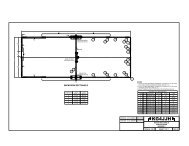
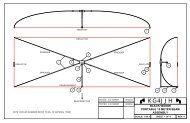
When the wire element is threaded though the 1 / 8 ” hole and the thumbscrew is tightenedto hold the wire the spreader clamps become part of the element assembly. Label the fourspreader clamp/element assemblies to shorten assembly time.BoomThe 10’ boom is made from two 1 1 / 2 ”OD x 6’ aluminum tubes joined together with athree foot length of 1 3 / 8 ”OD aluminum tubing and hardware. If the tubing is slit on oneend, install them with the slit ends on the outside and then trim to length after the antennais assembled and tested. An 8” x 12” x 3 / 16 ” thick aluminum plate with stainless steel U-bolts forms the boom to mast bracket.Spreader HubThe four spreader hubs are cut from a piece of 2 x 4 synthetic lumber on a table saw.Drill the 1 1 / 2 ” and 3 / 8 ” holes with a Forstner bit and drill press. Enlarge the 1 1 / 2 ” boomholes using a dowel wrapped with sandpaper to allow the hubs to slide onto the boom. A1 / 4 -20 x 1” long setscrew secures each hub to the boom.<strong>Element</strong>sMeasure the #12 Flexweave elements and cut them to the lengths in Table 1. Avoidstretching the Flexweave wire when measuring or else the elements will be too long.Mark the wire corners with a permanent marker and place marks 3 / 8 ” on either side of thecorner marks. The next step is to thread the element wire through four spreader clamps.Center each clamp between the 3 / 4 ” wide marks made earlier and tighten the thumbscrewto lock the elements in place. Uninsulated butt splices were used for completing theReflector, Director-1 and Director-2 loops and they seem to work well. Tin 1 / 4 ” of theelement wire ends, insert them fully into the butt splices, secure with Sta-Kon® typecrimpers, and solder both sides.Table 1<strong>6m</strong> 4-<strong>Element</strong> <strong>Quad</strong> Dimensions(All dimensions in inches)Ref DE Dir-1 Dir-2Spreader Length 45.375 44.25 43.375 42.75Circumference 250.0 242.0 237.5 234.0Side Length 62.5 60.50 59.375 58.51 st Corner Mark 31.25 30.25 29.6875 29.252 nd Corner Mark 93.75 90.75 89.0625 87.753 rd Corner Mark 156.25 151.25 148.4375 146.254 th Corner Mark 218.75 211.75 207.8125 204.75Total Wire Length 250.0 244.0 237.5 234.0For the Driven <strong>Element</strong>, insert the wires through the center insulator and wrap and solderboth sides. The middle of the center insulator should be 30 1 / 4 ” from each corner mark.The feedpoint should be fabricated to minimize extra wire lengths to the antennaconnector. Long coax pigtails will detune the Driven <strong>Element</strong> and lower resonance. Forthe prototype, a one foot length of RG8X coax with a female SO-239 connector on one<strong>6m</strong> 4-<strong>Element</strong> <strong>Quad</strong>, <strong>KG4JJH</strong> Page 2 of 5