
Create successful ePaper yourself
Turn your PDF publications into a flip-book with our unique Google optimized e-Paper software.
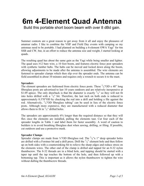
<strong>6m</strong> 4-<strong>Element</strong> <strong>Quad</strong> <strong>Antenna</strong>Build this portable short boom beam with over 8 dBd gain.Summer contests are a great reason to get away from it all and enjoy the pleasures ofamateur radio. I like to combine the VHF and Field Day events with camping so myantennas need to be portable. I had planned on building a 6-element OWA Yagi 1 for <strong>6m</strong>SSB and CW, but, in an effort to reduce the antenna size and weight, I started looking atquads.The resulting quad has about the same gain as the Yagi while being smaller and lighter.The quad uses #12 bare wire, a 10 foot boom, and features electric fence post spreaderswith synthetic lumber hubs. The hubs can be moved and locked down along the boom,allowing adjustments to be made after the antenna is assembled. The wire elements arefastened to spreader clamps which then slip over the spreader ends. The antenna can befield assembled in about 10 minutes and requires only a wrench to secure it to the mast.SpreadersThe element spreaders are fashioned from electric fence posts. These 3 / 8 ”OD x 48” longfiberglass posts are advertised to last 10 years outdoors and are relatively inexpensive at$1.09 apiece. The only drawback is that the diameter is exactly 3 / 8 ” so they will not fitinto holes drilled with a 3 / 8 ” bit. Therefore, the last inch on both ends is reduced toapproximately 0.370”OD by chucking the rod into a drill and holding a file against therod. Alternatively, 3 / 8 ”OD fiberglass tubing 2 can be used in lieu of the electric fenceposts. Although more expensive, they are manufactured with a reduced diameter thatallows them to fit in 3 / 8 ” drilled holes.The spreaders are approximately 6% longer than the required distance so that they willflex once the elements are installed, pulling the elements taut. Cut four each of thespreader lengths in Table 1 and label them for faster assembly. A word of caution tobuilders is to avoid breathing fiberglass dust when sawing, drilling, or filing. If possible,cut outdoors and use a protective mask.Spreader ClampsSpreader clamps are made from ¾”OD fiberglass rod. The 3 / 8 ”x 1” deep spreader holesare drilled with a Forstner bit and a drill press. Drill the 1 / 8 ” element hole and then followup on both sides with a countersinking bit to relieve the sharp edges and reduce stress onthe elements wires. The other end of the clamp is drilled and tapped for an 8-32 nylonthumbscrew. The 8-32 threads are in a blind hole, and tapping should be started with ataper tap until the tap touches the bottom of the hole, and then followed up with abottoming tap. This is important as it allows the nylon thumbscrew to tighten the wirewithout dulling the thumbscrew threads.<strong>6m</strong> 4-<strong>Element</strong> <strong>Quad</strong>, <strong>KG4JJH</strong> Page 1 of 5
When the wire element is threaded though the 1 / 8 ” hole and the thumbscrew is tightenedto hold the wire the spreader clamps become part of the element assembly. Label the fourspreader clamp/element assemblies to shorten assembly time.BoomThe 10’ boom is made from two 1 1 / 2 ”OD x 6’ aluminum tubes joined together with athree foot length of 1 3 / 8 ”OD aluminum tubing and hardware. If the tubing is slit on oneend, install them with the slit ends on the outside and then trim to length after the antennais assembled and tested. An 8” x 12” x 3 / 16 ” thick aluminum plate with stainless steel U-bolts forms the boom to mast bracket.Spreader HubThe four spreader hubs are cut from a piece of 2 x 4 synthetic lumber on a table saw.Drill the 1 1 / 2 ” and 3 / 8 ” holes with a Forstner bit and drill press. Enlarge the 1 1 / 2 ” boomholes using a dowel wrapped with sandpaper to allow the hubs to slide onto the boom. A1 / 4 -20 x 1” long setscrew secures each hub to the boom.<strong>Element</strong>sMeasure the #12 Flexweave elements and cut them to the lengths in Table 1. Avoidstretching the Flexweave wire when measuring or else the elements will be too long.Mark the wire corners with a permanent marker and place marks 3 / 8 ” on either side of thecorner marks. The next step is to thread the element wire through four spreader clamps.Center each clamp between the 3 / 4 ” wide marks made earlier and tighten the thumbscrewto lock the elements in place. Uninsulated butt splices were used for completing theReflector, Director-1 and Director-2 loops and they seem to work well. Tin 1 / 4 ” of theelement wire ends, insert them fully into the butt splices, secure with Sta-Kon® typecrimpers, and solder both sides.Table 1<strong>6m</strong> 4-<strong>Element</strong> <strong>Quad</strong> Dimensions(All dimensions in inches)Ref DE Dir-1 Dir-2Spreader Length 45.375 44.25 43.375 42.75Circumference 250.0 242.0 237.5 234.0Side Length 62.5 60.50 59.375 58.51 st Corner Mark 31.25 30.25 29.6875 29.252 nd Corner Mark 93.75 90.75 89.0625 87.753 rd Corner Mark 156.25 151.25 148.4375 146.254 th Corner Mark 218.75 211.75 207.8125 204.75Total Wire Length 250.0 244.0 237.5 234.0For the Driven <strong>Element</strong>, insert the wires through the center insulator and wrap and solderboth sides. The middle of the center insulator should be 30 1 / 4 ” from each corner mark.The feedpoint should be fabricated to minimize extra wire lengths to the antennaconnector. Long coax pigtails will detune the Driven <strong>Element</strong> and lower resonance. Forthe prototype, a one foot length of RG8X coax with a female SO-239 connector on one<strong>6m</strong> 4-<strong>Element</strong> <strong>Quad</strong>, <strong>KG4JJH</strong> Page 2 of 5
end and wire pigtails on the other end was fabricated. Remove 2” of outer insulator andinstall heat shrink tubing over the shield. Seal the open coax with silicone and heat shrinktubing over of the insulation cut. Solder the coax wires to the element on each side of thecenter insulator and use wire ties to secure the coax to the center insulator.Dimensions and ModelingThe dimensions for the quad are based on a design by G0KSC 3 . I modeled his antenna inEZNEC and was delighted with the wide flat bandwidth, similar to an OWA Yagi.Using EZNEC 4, the free space model indicates a gain of 10.25 dBi and 20 dB F/B ratioat 50.150 MHz. In reference to a free space dipole (2.15 dBi), the quad gain is 8.1 dBd.For the region of interest (50 to 50.5 MHz), the gain and SWR are relatively flat with a22.5 dB F/B peak at 50.45 MHz. The modeled 50Ω SWR for 50, 50.15, and 50.5 MHz is1.08, 1.09, and 1.11, respectively (Figure 1). With the boom mounted at 25 feet elevationover average ground the modeled gain is 15.4 dBi, 21.4 dB F/B, with an 11° take-offangle.252015105050.0 50.1 50.2 50.3 50.4 50.5Gain (dBi) F/B (dB) SWRFigure 1Initial Assembly & AdjustmentSlide the hubs onto the boom to their approximate positions and assemble the boom usingfour thread-cutting stainless steel screws. Raise the boom to a convenient height andinsert the Reflector spreaders into the Reflector hub. Next, slide the corner clamps withattached Reflector element over the spreader tips, flexing the spreaders toward the rear as<strong>6m</strong> 4-<strong>Element</strong> <strong>Quad</strong>, <strong>KG4JJH</strong> Page 3 of 5
needed. Ensure that the spreaders are fully inserted into the hub and spreader clamps.Tension created from the flexed spreaders will keep the assembly secure. Repeat thisprocess for the remaining three elements, taking care to place the Driven <strong>Element</strong>feedpoint at the bottom.Carefully measure the element to element spacing on the assembly and slide the hubs asnecessary to meet the dimensions in Table 1. Assemble the boom to mast bracketbetween the Driven <strong>Element</strong> and Director-1 and adjust the position to balance theantenna. For the prototype, the center of the boom was in line with the Director-1element. Secure the hubs to the boom with the hub setscrews and mark the final hub andmounting bracket positions on the boom for future reference. Attach the coax to thefeedpoint and secure it to the mast or boom for minimum pull on the driven element.For portability, the antenna breaks down into easily transportable pieces:• 2 ea – 1 1 / 2 ”OD x 5’ boom with hubs and mounting bracket• 1 ea – 1 3 / 8 ”OD x 3’ boom connector• 16 ea – 3 / 8 ”OD spreaders (various lengths less than 4 feet long)• 4 ea – <strong>Element</strong>/Spreader clamp assembliesField DayOn the day before Field Day 2010, the antenna was assembled and hung from a treebranch at my campsite with the boom at 21 feet. An MFJ-259B antenna analyzer wasused to generate the data in Figure 2.Figure 2Although the resulting plot revealed resonance 200 KHz below the EZNEC prediction Idecided to give it the acid test and drive the antenna from a battery powered FT-817. If I<strong>6m</strong> 4-<strong>Element</strong> <strong>Quad</strong>, <strong>KG4JJH</strong> Page 4 of 5
could make contacts with 5 watts I would consider the antenna a success. Deviations inthe SWR resonance were noted when the quad was pointed toward or away from the treetrunk which was about 12 feet from the center of the antenna. I suspect that the coaxpigtail wires increased the length of the driven element and lowered resonance. If this isthe case, the driven element should be shortened to 240.375”.I took a different approach to Field Day this year. Instead of hanging around 20m wherethere was sure to be lots of activity, I chose to limit the bands to <strong>6m</strong> and 10m. I was verysurprised to see PSK activity on 10 meters and worked as many as possible. On 6 metersthe quad exhibited excellent directivity and gain. Several QSOs were completed using 5watts into New York and Canada from my campsite at Norris Dam Sate Park inTennessee. While my <strong>6m</strong> signal reports weren’t 59s I was nonetheless elated. Comparedto my 4 dBd Moxon antenna 4 , the quad has more than double the gain and appears to bequieter.SummaryThe <strong>6m</strong> 4-<strong>Element</strong> <strong>Quad</strong> is about 38% smaller in area than the <strong>6m</strong> 6-<strong>Element</strong> OWA Yagiand weighs about 16 1 / 2 pounds. Compared to the Yagi, the quad has the same gain, lessaverage F/B, and a narrower bandwidth. However, bandwidth isn’t critical for CW andSSB operation centered around 50.150 MHz. This was my first quad and I heartilyrecommend it to anyone looking to improve their 6 meter station. To aid in constructionand setup, detailed drawings are available at my website. 5Allen Baker211 Brochardt Blvd.Knoxville, TN 37934http://www.kg4jjh.comReferences1. “Route 66, 6-Meter 6-<strong>Element</strong> OWA Yagis in 9 Versions”, L.B. Cebik, W4RNL,http://cebik.com/content/a10/vhf/66.html2. Max-Gain Systems, Inc., Fiberglass Products, http://www.mgs4u.com/fiberglasstube-rod.htm3. “G0KSC SC0604Q 4el 50MHz OWA <strong>Quad</strong> <strong>Antenna</strong> with a 2.988 Metre LengthBoom”, Justin Johnson, G0KSC, http://www.g0ksc.co.uk/sc0604q.html4. “A 6 Meter Moxon”, Allen Baker, <strong>KG4JJH</strong>, QST April 2004, pp 65-69.5. “<strong>6m</strong> 4-<strong>Element</strong> <strong>Quad</strong>”, Allen Baker, <strong>KG4JJH</strong>, http://www.kg4jjh.com/quad<strong>6m</strong> 4-<strong>Element</strong> <strong>Quad</strong>, <strong>KG4JJH</strong> Page 5 of 5