下载: dSPACE Magazine 3/2009
下载: dSPACE Magazine 3/2009
下载: dSPACE Magazine 3/2009

You also want an ePaper? Increase the reach of your titles
YUMPU automatically turns print PDFs into web optimized ePapers that Google loves.
<strong>dSPACE</strong><br />
magazine<br />
Hyundai – The fast track<br />
to variable valve control<br />
Mitsubishi Motors –<br />
i-MiEV runs on electricity<br />
Liebherr – Fuel cells deliver<br />
emergency power for aircraft<br />
www.dspace.com<br />
3/<strong>2009</strong><br />
<strong>dSPACE</strong> <strong>Magazine</strong> 3/<strong>2009</strong> · © <strong>dSPACE</strong> GmbH, Paderborn, Germany · info@dspace.com · www.dspace.com
PAGE 2<br />
Headschneller<br />
Aktive<br />
Schwingungsdämpfung<br />
für<br />
<strong>dSPACE</strong> <strong>Magazine</strong> 3/<strong>2009</strong> · © <strong>dSPACE</strong> GmbH, Paderborn, Germany · info@dspace.com · www.dspace.com
The automotive industry is well<br />
aware that it must invest in green<br />
technology. Not always necessarily<br />
for plausible reasons of physics or<br />
because it is always cost-efficient,<br />
but because of ever-present public<br />
and political pressure. What people<br />
tend to overlook is that reducing<br />
fuel consumption is one of the<br />
most expensive means of climate<br />
protection. In automotives, the cost<br />
of cutting emissions by one ton of<br />
CO 2 is one order of magnitude<br />
higher than in the power industry.<br />
From an economic viewpoint, our<br />
priorities should be different.<br />
As it is, some serious scientists are<br />
challenging the apocalyptic CO 2<br />
theories, and there are just as competent<br />
experts who do not see the<br />
age of oil ending so soon. They can<br />
point to numerous incorrect predictions<br />
from doom-and-gloom prophets<br />
in the past. There are even<br />
some people, not just hair-brained<br />
eccentrics, who say that the earth’s<br />
mantle also contains non-fossil<br />
(abiotic) oil, which is still forming<br />
today. Researchers recently verified<br />
that, in principle, anorganic carbohydrate<br />
synthesis is possible in the<br />
earth’s mantle (as published in the<br />
scientific journal “nature geoscience”).<br />
No matter who’s right, saving<br />
energy is always a good thing,<br />
especially whenever energy is being<br />
wasted or when saving it can be<br />
done at a comparatively low cost.<br />
But we shouldn’t ignore the issue<br />
of cost. The first place to make reductions<br />
is wherever they have the<br />
most effect. It cannot be said often<br />
enough – road vehicles are not the<br />
best place for that. In Europe, for<br />
example, they contribute only 12%<br />
to overall CO 2 emissions, and changing<br />
this percentage effectively is a longterm<br />
endeavor. The burning coal<br />
seams in India and China are each<br />
estimated to emit as much CO 2 as<br />
50 million cars. These things have to<br />
be viewed in proportion.<br />
Whatever viewpoint is correct,<br />
<strong>dSPACE</strong> is already actively involved<br />
in green technology. Our prototyp-<br />
Dr. Herbert Hanselmann<br />
President<br />
ing systems and code generator<br />
have been used in ecotechnology<br />
for quite a few years now. By the<br />
way, this <strong>Magazine</strong> issue comes<br />
with a special supplement edition<br />
on TargetLink, our code generator:<br />
TargetLink is celebrating 10 years<br />
of success!<br />
For green cars we offer special solutions<br />
for HIL simulation. Numerous<br />
hybrid and electric vehicle concepts<br />
were and are being tested with<br />
<strong>dSPACE</strong> systems. Our support for<br />
electric drive development goes<br />
back 20 years – we’re building test<br />
benches with real or simulated<br />
electric motors to electrify cars and<br />
aircraft systems. Battery simulation<br />
is one area we focus on. We have<br />
simulation models for electrical<br />
engineering, we have experts in<br />
power electronics, and we are<br />
constantly expanding these fields.<br />
If you need help, just ask us.<br />
Dr. Herbert Hanselmann<br />
President<br />
eDitorial<br />
<strong>dSPACE</strong> <strong>Magazine</strong> 3/<strong>2009</strong> · © <strong>dSPACE</strong> GmbH, Paderborn, Germany · info@dspace.com · www.dspace.com<br />
page 3
page 4 CoNteNtS<br />
IMPRInt<br />
hyuNDai Motor europe teChNiCal CeNter | page6<br />
page6<br />
<strong>dSPACE</strong> MAGAZINE is published periodically by:<br />
<strong>dSPACE</strong> GmbH · Technologiepark 25<br />
33100 Paderborn · Germany<br />
Tel.: +49 52 51 16 38-0<br />
Fax: +49 52 51 6 65 29<br />
dspace-magazine@dspace.com<br />
www.dspace.com<br />
Project Manager: André Klein<br />
Responsible in terms of the press law:<br />
Bernd Schäfers-Maiwald<br />
Authors: Ralf Lieberwirth, Sonja Lillwitz,<br />
Julia Reinbach, Nina Riedel, Dr. Gerhard Reiß<br />
Co-Workers on this issue: Dr. Ulrich Eisemann,<br />
Jürgen Klahold, Dr. Klaus Lamberg,<br />
Hisako Masuhara, Markus Plöger, Tino Schulze<br />
Editors and Translators:<br />
Robert Bevington, Stefanie Bock,<br />
Dr. Michelle Kloppenburg, Christine Smith<br />
Design: Krall & Partner, Düsseldorf<br />
Layout: Sabine Stephan<br />
Print: Merkur Druck, Detmold, Germany<br />
14<br />
MitSubiSHi MotoRS | page<br />
48<br />
EMH Solution | page<br />
© Copyright <strong>2009</strong><br />
All rights reserved. Written permission is<br />
required for reproduction of all parts of this<br />
publication. The source must be stated in<br />
any such reproduction.<br />
This publication and the contents hereof are<br />
subject to change without notice. Brand<br />
names or product names are trademarks or<br />
registered trademarks of their respective<br />
companies and organizations.<br />
<strong>dSPACE</strong> <strong>Magazine</strong> 3/<strong>2009</strong> · © <strong>dSPACE</strong> GmbH, Paderborn, Germany · info@dspace.com · www.dspace.com
liebherr-aeroSpaCe<br />
24<br />
liNDeNberg | page<br />
28<br />
EbERSpäcHER | page<br />
Contents<br />
3 eDitorial<br />
by Dr. Herbert Hanselmann,<br />
President<br />
Customers<br />
6 hyuNDai Motor europe teChNiCal CeNter<br />
Virtual Engine test Bench<br />
Test Bench of the Future: Real-time-capable<br />
thermodynamic engine models<br />
14 MitSubiShi MotorS<br />
Driving with no Emissions<br />
First Mitsubishi electric vehicle ready<br />
for launch<br />
18 VolVo teChNology<br />
Climate Under Control<br />
Volvo Technology Develops Climate<br />
Control Software with TargetLink<br />
24 liebherr-aeroSpaCe liNDeNberg<br />
never Without Power<br />
Developing an aircraft emergency power<br />
system based on a fuel cell<br />
28 eberSpäCher<br />
Silence is golden<br />
Active exhaust silencers in vehicles<br />
34 Delphi DieSel SySteMS<br />
Plug & Play<br />
ECU variants tested by automated<br />
sequences<br />
Products<br />
40 DS5203 Fpga boarD<br />
Speed and Flexibility<br />
For applications with extremely short<br />
latencies and cycle times<br />
44 hil api<br />
Platform Independence<br />
thanks to new Standard<br />
Standardized HIL API enables platformindependent<br />
HIL tests<br />
46 rti autoSar paCkage 1.0<br />
AUtOSAR now Boosts Rapid<br />
Prototyping and HIL<br />
Performing AUTOSAR components on<br />
<strong>dSPACE</strong> real-time hardware<br />
48 eMh SolutioN<br />
All Under One Roof<br />
EMH Solution – New integrated HIL simulation<br />
of electric motors<br />
52 rapiDpro MoDule<br />
Full Power<br />
Universal RapidPro Power Stage Modules<br />
for Electric Motors<br />
Business<br />
54 teStiNg at DSpaCe – iNterView<br />
Getting Better and Better<br />
The past, present, and future of test<br />
automation<br />
56 japaN uSer CoNFereNCe<br />
Japan Meets the Challenges<br />
The news from the <strong>dSPACE</strong> Japan User<br />
Conference <strong>2009</strong><br />
60 CoMpaCt NewS<br />
<strong>dSPACE</strong> <strong>Magazine</strong> 3/<strong>2009</strong> · © <strong>dSPACE</strong> GmbH, Paderborn, Germany · info@dspace.com · www.dspace.com<br />
page 5
page 6<br />
hyuNDai Motor europe teChNiCal CeNter<br />
Virtual<br />
Engine Test Bench<br />
Test bench of the future: Real-time-capable thermodynamic engine<br />
models at Hyundai Motor Europe Technical Center GmbH<br />
<strong>dSPACE</strong> <strong>Magazine</strong> 3/<strong>2009</strong> · © <strong>dSPACE</strong> GmbH, Paderborn, Germany · info@dspace.com · www.dspace.com
Variable valve systems improve the efficiency of<br />
modern gasoline engines. Testing the engine<br />
control units designed for them requires novel,<br />
detailed simulation models with high physical<br />
resolution. Rapid prototyping systems can be used<br />
in such precise simulation environments to test<br />
engine control functions in very early stages when<br />
no control units are available: another step towards<br />
a virtual test bench.<br />
Direct injection reduced fuel consumption<br />
in diesel engines, and<br />
new control concepts now promise<br />
to do the same for gasoline engines.<br />
Among them are homogeneous<br />
charged compression ignition<br />
(HCCI), variable valve control timing<br />
(VVT), and continuous variable<br />
valve lift (CVVL). These replace the<br />
classic throttle-based cylinder charge<br />
control and reduce gas exchange<br />
losses, which greatly improves fuel<br />
consumption (see Technology Background<br />
on page 11). However, this<br />
new freedom to control valve<br />
opening and closing events and<br />
also valve lift (CVVL) involves extra<br />
work in developing and calibrating<br />
engine control functions. It also<br />
creates new demands on hardwarein-the-loop<br />
simulation (HIL) on a<br />
virtual engine test bench. Up to<br />
now, mean value models were used,<br />
but these need now to be extended<br />
to represent the effects of the new<br />
control organs on engine processes.<br />
On the positive side, the new detailed<br />
engine models will also allow<br />
some classic calibration tasks to be<br />
moved from a real engine test<br />
bench to a HIL test bench. Thus, the<br />
new physical, real-time-capable engine<br />
models streamline the modelbased<br />
development process and<br />
make development as a whole lot<br />
more efficient.<br />
<strong>dSPACE</strong> <strong>Magazine</strong> 3/<strong>2009</strong> · © <strong>dSPACE</strong> GmbH, Paderborn, Germany · info@dspace.com · www.dspace.com<br />
page 7
page 8<br />
hyuNDai Motor europe teChNiCal CeNter<br />
Figure 1: Design of the HIL system with a production ECU, a rapid prototyping system for the new CVVL functions, and a real load for determining<br />
the actual valve train value.<br />
Development of Continuously<br />
Variable Valve Lift<br />
In an advanced engineering project<br />
at the Hyundai Motor Europe Technical<br />
Center (HMETC) in Rüsselsheim,<br />
Germany, engine control<br />
functions are being analyzed for a<br />
gasoline engine with continuously<br />
variable valve lift. An existing gasoline<br />
engine electronic control unit<br />
(ECU) has been extended by an ECU<br />
function for variable valve lift by using<br />
a <strong>dSPACE</strong> AutoBox as a prototyping<br />
system in bypass mode (see Technology<br />
Background). The new ASM<br />
Gasoline Engine InCylinder models<br />
are based on in-cylinder pressure,<br />
and are used to test and calibrate<br />
the new functions on the HIL test<br />
Patrizio Agostinelli<br />
Production ECU<br />
I/O signals<br />
HIL simulator<br />
Patrizio Agostinelli is responsible for<br />
developing new control concepts for<br />
advanced gasoline engines at Hyundai<br />
Motor Europe Technical Center in<br />
Rüsselsheim, Germany.<br />
LVDS<br />
AutoBox CVVL ECU<br />
CAN gateway<br />
bench at an early stage of development.<br />
ASM Gasoline InCylinder models are<br />
part of the Automotive Simulation<br />
Models (ASM) from <strong>dSPACE</strong>.<br />
Structure of the Controller<br />
Prototype<br />
To develop the new engine controls,<br />
the existing production ECU for a<br />
throttle-controlled gasoline engine<br />
is being used alongside a <strong>dSPACE</strong><br />
AutoBox that executes the new<br />
functions. The throttle-based cylinder<br />
charge control on the production<br />
ECU was deactivated. The new variable<br />
valve lift functions on the prototyping<br />
system replace the old cylinder<br />
charge control and are executed by<br />
the ECU in bypass mode (see Technology<br />
Background). Most of the<br />
existing structure of the production<br />
ECU can therefore be left as it was.<br />
Functions of the HIL Simulator<br />
The task of the HIL system is to simulate,<br />
in real time, the interaction<br />
between the charge request on the<br />
production ECU, the charge control<br />
on the prototyping system, and the<br />
engine charge calculated by the<br />
model. The new in-cylinder-based<br />
engine models in ASM Gasoline In-<br />
Cylinder are used to calculate the<br />
effect of variable valve lift on the<br />
engine process. This new generation<br />
of engine models calculates the<br />
cylinder charge as a function of the<br />
gas mix flowing through the inlet<br />
CAN<br />
I/O signals<br />
Mechanical CVVL<br />
assembly<br />
and outlet valves, making it easy to<br />
include the effect of variable valve<br />
trains in the simulation. In this project,<br />
the modular structure of the<br />
open model made the integration of<br />
the valve lift variability on the inlet<br />
side easy.<br />
Technical Implementation<br />
The production engine ECU was<br />
extended by a DCI-GSI bypass and<br />
calibration module to make a development<br />
ECU, which was connected<br />
to the prototyping system <strong>dSPACE</strong><br />
AutoBox via a fast low-voltage differential<br />
signaling (LVDS) connection<br />
(figure 1). The required cylinder<br />
charge is calculated on the production<br />
ECU and is transferred to the<br />
functions under development on<br />
the AutoBox via the LVDS connection.<br />
The functions calculate the required<br />
valve lift and send it via CAN<br />
bus to another satellite ECU, the<br />
CVVL driver, which contains the<br />
valve lift position controller. To implement<br />
realistic feedback for the<br />
CVVL driver’s position sensors, the<br />
mechatronic part of the valve train<br />
was constructed as a real load so<br />
that the CVVL driver ECU can operate<br />
in a closed control loop. In addition,<br />
a substitute model of the<br />
CVVL system was installed on the<br />
HIL system. The HIL simulation of<br />
the variable valve lift can therefore<br />
use either the measured lift from<br />
the real load, or the modeled lift.<br />
<strong>dSPACE</strong> <strong>Magazine</strong> 3/<strong>2009</strong> · © <strong>dSPACE</strong> GmbH, Paderborn, Germany · info@dspace.com · www.dspace.com
“ By using the HIL simulator and the new in-cylinder pressure-based engine<br />
models, we were able to develop and validate new algorithms for the<br />
charge control of a gasoline engine with continuously variable valve lift<br />
very quickly and very efficiently, and then to use them successfully<br />
in a prototype vehicle.”<br />
The necessary signals between the<br />
AutoBox and the CVVL driver are<br />
passed to the HIL simulation via a<br />
CAN gateway. This means that the<br />
HIL system can also be put into operation<br />
without a real load plus<br />
CVVL driver, which increases maintainability<br />
and flexibility, and helps<br />
pinpoint possible sources of error.<br />
Function Structure of Controller<br />
and Controlled System<br />
The production ECU calculates the<br />
driver torque demand from the current<br />
engine speed and accelerator<br />
position, after which the required<br />
reference variable, the cylinder<br />
charge, is determined (figure 2). The<br />
task of the charge control consists in<br />
calculating the appropriate charge<br />
influencing control variables for any<br />
given required cylinder charge. Leaving<br />
aside the effect of valve timing<br />
for the sake of simplicity, it can be<br />
said that in conventional systems,<br />
the main control variable is the<br />
throttle. In CVVL operation, the control<br />
variable is the lift of the inlet<br />
valve. The conversion from one variable<br />
to the other is executed on the<br />
AutoBox, usually via a model-based<br />
feedforward control overlaid by an<br />
Patrizio Agostinelli, Hyundai Motor Europe Technical Center<br />
Figure 2: The development ECU, consisting of a production ECU and the AutoBox, is connected to an HIL simulator.<br />
Production ECU<br />
Calculate<br />
desired engine<br />
torquet<br />
HFM sensor<br />
Calculate<br />
charge setpoint<br />
Calculate<br />
charge -> throttle<br />
position<br />
Position<br />
controller<br />
ASM Gasoline Engine<br />
InCylinder Model<br />
Calculate<br />
charge -><br />
valve lift<br />
adaptation algorithm that compensates<br />
for any model error. The calculated<br />
reference valve lift is sent to the<br />
CVVL driver, which is in charge of<br />
the valve lift control and returns the<br />
actual lift. The actual lift is used together<br />
with other variables, such as<br />
intake pressure/temperature, engine<br />
speed, and valve timing, to calculate<br />
the actual cylinder charge. For adaptation,<br />
the measured cylinder charge<br />
is also required. To obtain it, the ECU<br />
evaluates the mass flow in the air<br />
intake system via a hot film air mass<br />
meter (HFM).<br />
In this set-up of a production ECU<br />
AutoBox CVVL ECU<br />
Mechanical<br />
CVVL assembly<br />
Valve lift<br />
Measured<br />
valve lift<br />
Position<br />
controller<br />
Sensor<br />
Actuator<br />
ECU-internal signals<br />
CAN<br />
<strong>dSPACE</strong> <strong>Magazine</strong> 3/<strong>2009</strong> · © <strong>dSPACE</strong> GmbH, Paderborn, Germany · info@dspace.com · www.dspace.com<br />
page 9
page 10<br />
hyuNDai Motor europe teChNiCal CeNter<br />
with rapid prototyping and HIL<br />
systems, all the necessary measurement<br />
variables can be obtained<br />
from the plant model executed on<br />
an HIL simulator. For example, the<br />
engine model provides the simulated<br />
mass flow in the air intake system.<br />
Physically based simulation<br />
makes it possible to simulate the<br />
mass flow as a function of the controlled<br />
inlet valve lift (figure 3).<br />
Evaluation of the Development<br />
System<br />
This combination of an HIL simulator,<br />
a prototyping bypass system<br />
and physical engine models enables<br />
Conclusion<br />
The new valve adjustment techniques<br />
also necessitate new methods<br />
and models for HIL testing. The<br />
physical engine models made it<br />
possible to test the ECU project<br />
on the HIL system at a very early<br />
stage of development, without<br />
the new functionalities being implemented<br />
in the production ECU.<br />
Instead, a bypass system was used<br />
in conjunction with a production<br />
ECU. The in-cylinder pressurebased<br />
engine models made it<br />
possible to perform not only pure<br />
function tests but also precalibration<br />
tasks for the new controller<br />
concept on the HIL test bench,<br />
which reduced the number of<br />
real test bench trials that were<br />
necessary. In downstream development<br />
steps, being able to reuse<br />
test scenarios is a great advantage.<br />
Since they were already implemented<br />
for the production ECU<br />
with the rapid control prototyping<br />
system, they can now be used for<br />
the subsequent prototype phase.<br />
Valve Lift [mm]<br />
10<br />
8<br />
6<br />
4<br />
2<br />
0<br />
0 30 60 90 120 150 180<br />
Cam Angle [deg]<br />
Figure 3: Variable valve lifts for CVVL integrated into ASM Gasoline Engine InCylinder Models.<br />
plausible real-time simulation of<br />
new engine ECU functions in a very<br />
early development phase. The engine<br />
model was parameterized relatively<br />
quickly by means of test bench<br />
measurement data, so that the<br />
modeled and the measured values<br />
were a good match. The in-cylinder<br />
pressure model calculates the pressure<br />
and mass flow values with sufficient<br />
precision, and the ECU can<br />
be operated without errors. Even<br />
engine operating conditions with<br />
valve timing and lift combinations<br />
that were not measured on the<br />
engine test bench can also be simulated<br />
plausibly.<br />
The open models make it easy to<br />
extend the simulation model. The<br />
required parameters and measurement<br />
variables can easily be found<br />
and visualized in real-time calibration.<br />
Benefit: Precalibration by<br />
Simulator<br />
Not only pure function tests can be<br />
performed. The parameters of the<br />
controller can also be precalibrated<br />
at an early stage on the HIL system,<br />
so the rapid control prototyping<br />
system goes into operation on the<br />
engine test bench with a suitably<br />
parameterized controller. This<br />
means that some of the necessary<br />
experimenting activities can be<br />
moved from the expensive engine<br />
test bench to the comparatively inexpensive<br />
HIL simulator. By combining<br />
HIL and rapid control prototyping in<br />
controller development, users have<br />
more flexibility in calibrating and<br />
structuring the controller. Moreover,<br />
it also enables them to modify the<br />
parameters and submodels in the<br />
plant itself, making it easy to study<br />
different variants. This task would<br />
require time-consuming and costintensive<br />
adaptation work on the<br />
test bench.<br />
Benefit: Frontloading by Linking<br />
RCP and HIL<br />
Another advantage is that the models,<br />
layouts and automated tests from<br />
the HIL test bench can be reused<br />
after the extended functionality has<br />
been transferred from the rapid<br />
prototyping ECU to the production<br />
ECU. This new ECU also has to be<br />
tested thoroughly. Developers can<br />
use the existing model and the experiment<br />
environment from the<br />
earlier development phase for this.<br />
In other words, the new physical<br />
models improve integration between<br />
the development process on the HIL<br />
system and the development process<br />
on the real test bench, both during<br />
the controller development phase<br />
and during subsequent function<br />
testing.<br />
Patrizio Agostinelli<br />
Hyundai Motor Europe Technical Center<br />
GmbH, Germany<br />
<strong>dSPACE</strong> <strong>Magazine</strong> 3/<strong>2009</strong> · © <strong>dSPACE</strong> GmbH, Paderborn, Germany · info@dspace.com · www.dspace.com
Technology Background<br />
The technologies and development methods used in the CVVL<br />
engine test bench<br />
Future Gasoline Engine<br />
Concepts<br />
Combustion engines run on a<br />
mixture of fuel and air. Engine<br />
designers use two characteristics<br />
to describe the mixture. The first<br />
is the air/fuel ratio that is required<br />
to burn off precisely the injected<br />
quantity of fuel, called the stoichiometric<br />
ratio. In a gasoline<br />
engine, it is 14.6, though it also<br />
depends on the fuel. In other<br />
words, 14.6 kg of air is required<br />
to burn 1 kg of fuel. The second<br />
important characteristic is the<br />
lambda value. This indicates the<br />
extent to which the mixture already<br />
taken in deviates from the<br />
stoichiometric ratio. In gasoline<br />
engines, the engine performance<br />
is controlled via the quantity of<br />
gas mixture that is taken in. The<br />
appropriate amount of fuel for<br />
the fresh air quantity is injected<br />
before the cylinders, where it<br />
mixes with the air. This fuel/air<br />
mixture is mostly stoichiometric,<br />
i.e., there is always precisely the<br />
right amount of air to burn the<br />
fuel. Thus, in gasoline engines<br />
with their gas mixture intake,<br />
there is no direct way of controlling<br />
engine performance via the<br />
injected fuel quantity, as the con-<br />
trol always maintains a lambda<br />
value of one. To allow a specific<br />
quantity of fuel to be injected,<br />
the quantity of fresh air has to be<br />
controlled.<br />
The classic method of implementing<br />
this type of charge control is<br />
to use a throttle. This reduces the<br />
cross-section area in the engine’s<br />
intake system, thereby controlling<br />
the air pressure before the inlet<br />
valves. The appropriate fuel for<br />
the given air pressure is injected<br />
before the inlet valves to form the<br />
fuel/air mixture. When the inlet<br />
valves open, this mixture is sucked<br />
into the cylinder at the currently<br />
set air pressure. The lower the air<br />
pressure that the throttle sets, the<br />
lower the mass of the mixture in<br />
the cylinder after the inlet valve<br />
closes. The volume of the mixture<br />
remains approximately constant.<br />
This means that the mass of fuel<br />
that is taken in is also lower, as it<br />
is in a constant ratio to the mass<br />
of the air. The setting of the intake<br />
manifold pressure can therefore<br />
be used to implement a charge<br />
control. The disadvantage of this<br />
method is that the lower the air<br />
pressure before the valves, the<br />
more work is needed to draw in<br />
The Hyundai Motor Europe Technical Center (HMETC) in Rüsselsheim, Germany.<br />
the mixture. This so-called gas<br />
exchange work has to be performed<br />
by the cylinders in which<br />
combustion takes place, so it<br />
reduces the power available at<br />
the crankshaft.<br />
With variable valve trains, i.e.<br />
with variable valve timing and/or<br />
variable valve lift, the quantity of<br />
mixture in the gasoline engine<br />
can be set for the entire load/engine<br />
speed map without using a<br />
throttle. The gas exchange work,<br />
and therefore also fuel consumption,<br />
can be reduced because the<br />
mixture can be taken in under<br />
ambient conditions across the<br />
entire load/engine speed range<br />
(figure 4).<br />
In addition, the internal exhaust<br />
gas recirculation and the proportion<br />
of residual gas in the cylinder<br />
can be controlled by varying the<br />
spread of the inlet and outlet<br />
valves. Removing the throttle and<br />
improving the air/fuel mix increases<br />
the gasoline engine’s efficiency<br />
and reduces fuel consumption.<br />
HIL Tests<br />
Hardware-in-the-loop (HIL) simulators<br />
allow reproducible and automatable<br />
function testing of elec-<br />
<strong>dSPACE</strong> <strong>Magazine</strong> 3/<strong>2009</strong> · © <strong>dSPACE</strong> GmbH, Paderborn, Germany · info@dspace.com · www.dspace.com<br />
page 11
page 12<br />
hyuNDai Motor europe teChNiCal CeNter / teChNology baCkgrouND<br />
Cylinder pressure<br />
Throttle control<br />
IVO<br />
EVC<br />
TDC volume BDC TDC volume BDC TDC volume BDC<br />
EVO: exhaust valve opens<br />
EVC: exhaust valve closes<br />
EVO<br />
tronic control units with a virtual<br />
engine. The ECU actuator signals<br />
are read by I/O boards and provided<br />
to a real-time engine model,<br />
which calculates the engine<br />
behavior from the available information<br />
and generates plausible<br />
sensor values that are returned to<br />
the ECU as electric signals. This<br />
makes it possible to run tests in a<br />
closed control loop with a simulated<br />
engine.<br />
Engine Simulation Models<br />
Real-time engine simulation currently<br />
uses what are called mean<br />
value models. With these, all the<br />
simulated engine operating data<br />
is averaged across one working<br />
cycle, i.e. for two crankshaft rotations<br />
of the engine, and simulated.<br />
This type of model provides<br />
sufficient quality for the majority<br />
of HIL test benches. It is a sensible<br />
compromise between simulation<br />
precision, computing time<br />
require ment and parameterization<br />
effort. However, future engine<br />
concepts will make tougher<br />
Cylinder pressure<br />
IVC EVC<br />
IVO: inlet valve opens<br />
IVC: inlet valve closes<br />
CVVL control<br />
Early inlet valve closing<br />
IVO<br />
IVC<br />
EVO<br />
TDC: top dead center<br />
BDC: bottom dead center<br />
demands on real-time-capable<br />
simulation models. Diesel engines<br />
with in-cylinder pressure measurement<br />
and gasoline engines<br />
with variable valve control times<br />
and valve lift require new, realtime-capable<br />
models that describe<br />
the engine process far<br />
more precisely than the current<br />
mean value models. These in-cylinder<br />
pressure models make it<br />
possible to calculate the cylinder<br />
charge, for example, by simulating<br />
the flows through the inlet<br />
and outlet valves. No look-up<br />
tables for cylinder charging are<br />
used. Instead, the mass flow<br />
between the air system and the<br />
cylinder is calculated as a function<br />
of the valve opening and closing<br />
timing and the current valve lift,<br />
so that the quantity of the mixture<br />
in the cylinder is provided<br />
automatically by the simulation.<br />
This means that the simulation<br />
can also take into account changes<br />
in valve lift and valve timing.<br />
Figure 5 shows the basic simulation<br />
approach, which is based on<br />
CVVL control<br />
Late inlet valve closing<br />
Figure 4: Gas exchange work for gasoline engines with throttle (left) and with variable valve lift (center and right).<br />
Cylinder pressure<br />
EVC<br />
IVO<br />
IVC<br />
EVO<br />
the first law of thermodynamics,<br />
mass balances for fresh air, fuel<br />
and exhaust gas, and the ideal<br />
gas law. The states inside the cylinder<br />
are calculated as functions<br />
of the combustion, piston work,<br />
wall heat losses and enthalpy<br />
flows through the inlet and outlet<br />
valves. This enables values such<br />
as pressure, temperature and<br />
masses to be represented as timedependent<br />
behaviors with a step<br />
size of 100 µs for now.<br />
Rapid Prototyping<br />
Rapid prototyping is a proven<br />
technology for implementing and<br />
testing new control algorithms on<br />
the real plant. A control algorithm<br />
that was developed in Simulink<br />
can be downloaded directly to<br />
powerful prototyping hardware<br />
via autocoding. The algorithm<br />
can be connected to the plant via<br />
the I/O interfaces already defined<br />
in the Simulink model. In the ECU<br />
development process, a distinction<br />
is made between fullpassing and<br />
bypassing.<br />
<strong>dSPACE</strong> <strong>Magazine</strong> 3/<strong>2009</strong> · © <strong>dSPACE</strong> GmbH, Paderborn, Germany · info@dspace.com · www.dspace.com
Energy balance<br />
Thermal equation of states Mass balance<br />
P Cyl<br />
dU<br />
dφ<br />
=<br />
= –<br />
Fullpassing<br />
Bypassing<br />
p<br />
m Cyl R Cyl T Cyl<br />
V Cyl<br />
Host PC<br />
Rapid prototyping<br />
systems<br />
Bypass<br />
interfaces<br />
Production controller (ECU)<br />
m Throttle<br />
m inMan<br />
work hot release rate wall heat enthalpy<br />
Figure 5: Equations in the in-cylinder pressure model.<br />
In fullpassing, an entire ECU is represented<br />
on the prototyping hardware<br />
and controls an engine, etc.<br />
In bypassing, an existing engine<br />
ECU is extended by a functionality<br />
on the prototyping hardware<br />
Signal conditioning,<br />
power stages<br />
T inMan P inMan<br />
dV dQFuel dQWall dm In<br />
+ – + hIn –<br />
dφ dφ dφ dφ dφ<br />
Figure 6: Rapid prototyping in fullpassing and bypassing.<br />
dm i, Cyl<br />
dt<br />
dmOut hOut = m i, In + m i, Inj + m i, Out ± m i, Burned<br />
(figure 6). For example, cylinder<br />
charging is not controlled by<br />
means of the throttle. Instead, the<br />
desired charge is forwarded to the<br />
new control algorithm on the prototyping<br />
ECU as a reference value.<br />
Plant<br />
m In<br />
m Cyl’<br />
dQ Fuel<br />
T Cyl’<br />
Glossary<br />
dW<br />
w<br />
m Out<br />
dQ Wall<br />
The algorithm then calculates the<br />
necessary valve lift. This set-up<br />
allows the previous ECU to remain<br />
in use.<br />
CVVL – Continuous variable valve lift<br />
allows the lift, duration or timing of intake<br />
and exhaust valves to be changed<br />
while the engine is in operation.<br />
DCI GSI – Low-latency bypass interface<br />
for connecting <strong>dSPACE</strong> prototyping systems<br />
to a host PC<br />
HCCI – Homogeneous charged compression<br />
ignition. A form of combustion in<br />
which well-mixed fuel and air are compressed<br />
to the point of self-ignition in<br />
the entire combustion chamber.<br />
LVDS – Low-voltage differential signalling,<br />
an interface standard for highspeed<br />
data transmission.<br />
<strong>dSPACE</strong> <strong>Magazine</strong> 3/<strong>2009</strong> · © <strong>dSPACE</strong> GmbH, Paderborn, Germany · info@dspace.com · www.dspace.com<br />
page 13
page 14<br />
MitSubiShi MotorS<br />
Driving<br />
with no emissions<br />
First Mitsubishi electric vehicle ready for launch<br />
<strong>dSPACE</strong> <strong>Magazine</strong> 3/<strong>2009</strong> · © <strong>dSPACE</strong> GmbH, Paderborn, Germany · info@dspace.com · www.dspace.com
Dr. Kazuya Hayafune, Vice<br />
Corporate General Manager,<br />
MiEV Development, Development<br />
Engineering Office<br />
Mitsubishi’s new electric vehicle, i-MiEV, lives and breathes by its complex<br />
electronics. Mitsubishi ran rigorous tests to ensure the quality of the software,<br />
yet still managed to cut the time-to-market.<br />
<strong>dSPACE</strong> <strong>Magazine</strong> 3/<strong>2009</strong> · © <strong>dSPACE</strong> GmbH, Paderborn, Germany · info@dspace.com · www.dspace.com<br />
page 15<br />
Masahiro Kaneda, Manager,<br />
Electronics Engineering Dept.,<br />
Development Engineering<br />
Office
page 16<br />
MitSubiShi MotorS<br />
Figure 1: The battery pack and electric motor of the i-MiEV enable emission-free driving.<br />
Development Outline<br />
The i-MiEV (Mitsubishi innovative<br />
electric vehicle) next-generation<br />
electric vehicle is literally an aggregation<br />
of electric and electronic<br />
components. Because its various<br />
functions are achieved by distributed<br />
control using an onboard network,<br />
ensuring the quality of the total<br />
vehicle system as well as that of the<br />
electronic control unit (ECU) software<br />
is vital. And at the production<br />
development stage, the quality of<br />
complex systems has to be verified<br />
within the limited time available.<br />
As a means of ensuring quality in<br />
the shortest possible time, software<br />
reliability testing was conducted<br />
Figure 2: Recharging the battery.<br />
“ In accordance with design content, <strong>dSPACE</strong><br />
Simulator offers a very high level of general<br />
versatility and can be used for almost any<br />
vehicle and ECU.”<br />
Dr. Kazuya Hayafune, MITSUBISHI MOTORS CORPORATION<br />
using a hardware-in-the-loop (HIL)<br />
simulator made by <strong>dSPACE</strong>.<br />
ECU Structure and System<br />
Specifications<br />
The i-MiEV’s electronic platform<br />
is characterized by a distributed<br />
control format that uses five<br />
dedicated ECUs.<br />
Figure 3: Schematic of the power train.<br />
Battery<br />
In addition to performing the<br />
conventional vehicle functions of<br />
driving, cornering, and stopping,<br />
electric vehicles also need the ability<br />
to recharge from a home power<br />
socket and rapid charger, and to<br />
run on an electric motor.<br />
For all this to be possible, the ECUs<br />
that control the electric vehicle<br />
Motor and<br />
transmission<br />
<strong>dSPACE</strong> <strong>Magazine</strong> 3/<strong>2009</strong> · © <strong>dSPACE</strong> GmbH, Paderborn, Germany · info@dspace.com · www.dspace.com<br />
Inverter<br />
On-board charger
Technical Details for <strong>2009</strong><br />
Japan Spec<br />
Max. power 64PS/47kW<br />
Max. torque 180 Nm<br />
Max. speed 130 km/h<br />
Battery Lithium ion<br />
Total voltage 330 V<br />
Total energy 16 kWh<br />
Range 160 kilometers<br />
(Japan 10-15<br />
driving pattern)<br />
Curb weight 1100 kg<br />
Battery recharge Approx. 7 hours<br />
(AC 200V/15A)<br />
Fast battery Approx. 30<br />
recharge minutes (80%<br />
charged)<br />
require reliable means to transmit<br />
vehicle control information.<br />
System Design Outline<br />
The five ECUs are connected<br />
through a key bus – a controller<br />
area network (CAN) bus. Multiple<br />
communication lines are provided<br />
as backups for when the key bus<br />
malfunctions.<br />
Issues and Corresponding<br />
Requirement<br />
n Issue 1: Ensure the quality of the<br />
software of Mitsubishi’s first dedicated<br />
electric vehicle ECUs.<br />
n Issue 2: Ensure the quality of the<br />
software of the overall electric<br />
vehicle system.<br />
n Issue 3: Achieve issue 2 within<br />
a limited development period.<br />
n Requirement: No defect should<br />
occur during any user operation<br />
whatsoever.<br />
Solutions<br />
n Issues 1 and 2: In line with the<br />
requirement specifications, the<br />
focus was on software processing<br />
as well as the branch conditions<br />
and state transitions of the vehicle’s<br />
total system. Specifically, we designed<br />
software tests for all inputs<br />
to the ECUs and vehicle systems.<br />
Figure 4: Team members responsible for electrical reliability of the i-MiEV.<br />
“ A <strong>dSPACE</strong> HIL simulator consists of visually easyto-understand<br />
components like Automation Desk.<br />
We found that this test automation software is<br />
extremely easy to use.”<br />
n Issue 3: Targeting all inputs resulted<br />
in an enormous number of<br />
test patterns. To reduce this number<br />
efficiently, an orthogonal design<br />
was used. <strong>dSPACE</strong> Simulator was<br />
used to reduce the number of<br />
testing man hours by automatic<br />
test execution.<br />
The Role of, and Expectations<br />
for <strong>dSPACE</strong> Simulator<br />
In executing the testing, it was<br />
necessary to adapt the test design<br />
content for the test patterns quickly<br />
and accurately. For the sake of<br />
analysis, a high level of replication<br />
was needed when software bugs<br />
were detected.<br />
Therefore, a <strong>dSPACE</strong> Simulator Mid-<br />
Size was used to simulate user operation<br />
and the inputs to the ECUs<br />
accompanying it during the design<br />
process. An actual vehicle was used<br />
for the real load on the HIL simulator.<br />
Masahiro Kaneda, MITSUBISHI MOTORS CORPORATION<br />
The test automation software AutomationDesk<br />
was used as a means<br />
of creating test patterns quickly.<br />
Evaluation of <strong>dSPACE</strong> Simulator<br />
<strong>dSPACE</strong> Simulator proved extremely<br />
effective in ensuring the quality of<br />
the software of the i-MiEV on<br />
schedule. If it had not been for the<br />
<strong>dSPACE</strong> Simulator, verifying software<br />
quality within the time available<br />
would have been problematic.<br />
Future Development<br />
While HIL-based verification was<br />
used on the right-hand side of the<br />
V-cycle in vehicle development, in<br />
the future a means of assuring software<br />
quality at a more upstream<br />
stage (left-hand side of the V-cycle)<br />
will be sought.<br />
Dr. Kazuya Hayafune, Masahiro Kaneda<br />
MITSUBISHI MOTORS CORPORATION, Japan<br />
<strong>dSPACE</strong> <strong>Magazine</strong> 3/<strong>2009</strong> · © <strong>dSPACE</strong> GmbH, Paderborn, Germany · info@dspace.com · www.dspace.com<br />
page 17
page 18<br />
VolVo teChNology<br />
Climate<br />
Under Control<br />
Volvo Technology develops climate control software with TargetLink<br />
<strong>dSPACE</strong> <strong>Magazine</strong> 3/<strong>2009</strong> · © <strong>dSPACE</strong> GmbH, Paderborn, Germany · info@dspace.com · www.dspace.com
Volvo Technology, the center for innovation, research and development<br />
in the Volvo Group, has been continuously refining and extending its<br />
established Climate Control Module (CCM) over the years. The software<br />
is used by several international car, truck and construction equipment<br />
brands. Volvo Technology makes intense use of TargetLink during the<br />
controller development, autocoding and tuning phases.<br />
<strong>dSPACE</strong> <strong>Magazine</strong> 3/<strong>2009</strong> · © <strong>dSPACE</strong> GmbH, Paderborn, Germany · info@dspace.com · www.dspace.com<br />
page 19
page 20<br />
VolVo teChNology<br />
Outside air<br />
Blower<br />
Recirculated<br />
air<br />
Expansion valve<br />
Simplified view of the climate unit (HVAC: heat, ventilation and air condition).<br />
Better Climate with CCM<br />
Volvo Technology’s main role for<br />
climate control developments is<br />
to deliver software which fulfils<br />
modern climate comfort requirements<br />
and addresses issues such as air<br />
demisting, odor and noise control,<br />
and energy efficiency. Current<br />
development is focused on improved<br />
efficiency in calibration for new<br />
vehicles and incorporation of new<br />
features and requirements. The<br />
development cycles are highly testdriven,<br />
and testing and tuning<br />
using prototypes and pre-series<br />
vehicles are common. <strong>dSPACE</strong>’s<br />
production code generator TargetLink<br />
plays a major role in Volvo Technology’s<br />
development process for<br />
function design, autocoding,<br />
tuning and testing.<br />
What Makes a Good Climate<br />
Control?<br />
Good climate control lets drivers<br />
select their preferred setting and<br />
then get exactly the comfort they<br />
expect. This means that the temperature<br />
in the passenger compartment<br />
is kept within a predefined<br />
range, there is no draught, the fan<br />
is not too noisy, it does not get<br />
cold when the sun goes in, the<br />
windscreen does not mist up, and so<br />
A/C<br />
Heater<br />
Condenser<br />
Evaporator<br />
on. To achieve all this, a climate controller<br />
has several control objectives:<br />
n Temperature Control<br />
This controls the heating, cooling,<br />
blower and air distribution to<br />
achieve fast heat-up/cool-down<br />
and a stable interior temperature in<br />
the passenger compartment during<br />
different driving conditions. It also<br />
compensates for disturbances such<br />
as high/low ambient temperature,<br />
sun load and vehicle speed.<br />
n Demisting Control<br />
The purpose is to keep the windscreen<br />
free from ice and mist. The<br />
control mainly uses the blower,<br />
defroster and cool/reheat with air<br />
conditioner (A/C) and heating<br />
system.<br />
n Odor Control<br />
The odor control, commonly<br />
known as AQS (Air Quality System),<br />
prevents unpleasant odors from<br />
entering the compartment via the<br />
outside/recirculated air flaps.<br />
n Parking Climate<br />
Passenger cars and commercial<br />
vehicles both have functions for<br />
controlling the interior climate<br />
while parked. In trucks, where the<br />
Floor<br />
Defroster<br />
Ventilation<br />
Compressor<br />
driver often stays in the cab overnight,<br />
this is particularly important<br />
and sets strict requirements on<br />
temperature comfort and noise.<br />
Typical Hardware for Climate<br />
Control<br />
Climate control requires a number<br />
of hardware items to make the<br />
control software work the way<br />
intended. One of them is the climate<br />
unit, often referred to as HVAC<br />
(heat, ventilation and air Condition).<br />
The recirculation enabled by<br />
the climate unit is primarily used for<br />
improving the cooling performance<br />
in a hot climate by recycling the air<br />
already cooled and dried. Another<br />
use of recirculation is for preventing<br />
odors and pollution from entering<br />
the compartment. The part of the<br />
HVAC that cools the air is the air<br />
conditioner (A/C), consisting of<br />
compressor, condenser, expansion<br />
valve and evaporator. A number of<br />
sensors are also important for climate<br />
control. Some of them, such<br />
as the passenger compartment<br />
temperature sensor and the evaporator<br />
temperature sensor, are typical<br />
of an Electronic Climate Controller<br />
(ECC). Other sensors such as the<br />
vehicle speed sensor or the ambient<br />
temperature sensor primarily exist<br />
<strong>dSPACE</strong> <strong>Magazine</strong> 3/<strong>2009</strong> · © <strong>dSPACE</strong> GmbH, Paderborn, Germany · info@dspace.com · www.dspace.com
for other systems in the vehicle, but<br />
are also important to the ECC.<br />
Inside the CCM<br />
The CCM is part of the electronic<br />
system in the vehicle and is connected<br />
to other subsystems on the networks<br />
via CAN and LIN. Some sensors and<br />
actuators are also hardwired to the<br />
CCM. The Climate Control itself<br />
provides all the functions described<br />
above, i.e., temperature control,<br />
demisting control, odor control, and<br />
parking climate. The CCM has been<br />
modularized into several functions.<br />
The controller input signals are processed<br />
first. This includes basic filtering<br />
and error handling as well as<br />
some sensor fusion and modeling<br />
to the data needed for the control<br />
algorithms. The controller structure<br />
is then function-oriented rather<br />
than actuator-oriented. This means<br />
that the modules for temperature,<br />
demisting and odor control all request<br />
actuator actions. After controller<br />
actions are prioritized, manual<br />
overrides from the driver are<br />
taken care of, and finally actuator<br />
actions are sent.<br />
Overview of the Development<br />
Process<br />
The CCM is an established product<br />
and so is the development process<br />
for it with TargetLink. Typically,<br />
new developments require the finetuning<br />
or extension of functionalities<br />
already present in the CCM, so<br />
that existing resources like software<br />
requirements, TargetLink models<br />
and test cases from previous projects<br />
are reused and adapted to<br />
meet the new requirements.<br />
In a simplified view, four different<br />
types of activities can be identified<br />
in the process:<br />
“ We autocode almost 100% of the application<br />
layer of our Climate Control Module with<br />
TargetLink.”<br />
Dr. Mats Andersson, Volvo Technology<br />
n Software requirement<br />
specification<br />
n Control design and<br />
implementation<br />
n Controller tuning<br />
n Test & validation.<br />
The development process is highly<br />
test- and experiment-driven and<br />
iterative. This is because a lot of<br />
the testing and fine-tuning for the<br />
CCM can only be done in-vehicle<br />
due to the difficulty in modelling<br />
the subjective perception of occupant<br />
comfort. This means that changes<br />
and updates to the control design<br />
need to be made iteratively to compensate<br />
for behavior overlooked in the<br />
initial stages of software require ment<br />
specifications and control design.<br />
Software Requirement<br />
Specification<br />
Requirements are supplied by the<br />
customer on a system level. These<br />
are often end customer use cases<br />
in the form of “Head level temperature<br />
must be between X and<br />
Y °C”. During the first iteration<br />
of the requirement specification<br />
phase, the system requirements are<br />
decomposed into meaningful software<br />
requirements. Some software<br />
requirements are also reused from<br />
previous projects. In subsequent<br />
iterations, some software require-<br />
Controller model and code: TargetLink was used to autocode almost<br />
the entire application layer of the CCM.<br />
<strong>dSPACE</strong> <strong>Magazine</strong> 3/<strong>2009</strong> · © <strong>dSPACE</strong> GmbH, Paderborn, Germany · info@dspace.com · www.dspace.com<br />
page 21
page 22<br />
VolVo teChNology<br />
ments need to be adapted as a<br />
result of in-vehicle tests and tuning.<br />
Controller Implementation<br />
The core functionality of the CCM<br />
exists in the form of a TargetLink<br />
model from which code has been<br />
deployed for various production<br />
projects. The actual control design<br />
is carried out entirely by Volvo<br />
Technology using the TargetLink<br />
Stand-Alone Blockset. The largest<br />
part of the control design work is<br />
done in the first iteration of the<br />
development process, where the<br />
existing TargetLink model is adapted<br />
to meet the new software requirements.<br />
In subsequent iterations,<br />
the control design is modified to<br />
reflect necessary changes in software<br />
requirements during the<br />
course of the project.<br />
LIN Sensors &<br />
Actuators<br />
Signal<br />
Processing<br />
Temperature<br />
Control<br />
Demisting<br />
Control<br />
Odor<br />
Control<br />
CCM<br />
Prioritize<br />
CAN<br />
Control design and implementation<br />
with TargetLink almost go hand in<br />
hand. Close to 100% of the application<br />
layer of the CCM is autocoded<br />
by TargetLink in the form of efficient<br />
fixed-point code. Moreover,<br />
TargetLink’s flexibility enables the<br />
generation of interfaces that are<br />
very well suited to a later integration<br />
into the software architecture of<br />
the CCM.<br />
Open loop and closed loop simulations<br />
are used to inspect the basic<br />
behavior of the controller as well as<br />
the generated code. Actual stimuli<br />
which were captured in vehicles and<br />
some simplified plant models are<br />
used for the simulations.,The overall<br />
system behavior of the controller is<br />
examined in floating-point arithmetic<br />
with Model-in-the-Loop (MIL)<br />
simulations. Software-in-the-loop<br />
Manual<br />
Overrides<br />
Actuators<br />
Hardwired Sensors &<br />
Actuators<br />
Physical interfaces to the Climate Control Module (CCM) and CCM controller modularization.<br />
Dr. Mats Andersson (left)<br />
Manager of Control and Simulation<br />
group at Volvo Technology, Sweden<br />
Björn Fridholm, M.Sc. (center)<br />
Control developer at Volvo Technology,<br />
Sweden<br />
Henrik Weiefors, M.Sc. (right)<br />
Control developer at Volvo Technology,<br />
Sweden<br />
(SIL) simulations are used to verify<br />
the behavior of the generated code<br />
for the controller. TargetLink’s integrated<br />
simulation concept is used to<br />
compare MIL with SIL simulations to<br />
detect improper scalings in the<br />
implementation model. The result of<br />
the Control Design and Implementation<br />
phase is a properly scaled<br />
TargetLink model and code generated<br />
from it.<br />
Controller Tuning<br />
Climate control essentially means<br />
controlling the air into the passenger<br />
compartment. The plant models<br />
used during the control design and<br />
implementation phase do not capture<br />
all of the subjective aspects of<br />
comfort and noise. Consequently<br />
the final tuning of the controller is<br />
performed in-vehicle, often starting<br />
in a prototype vehicle where some<br />
of the hardware is changed from an<br />
existing vehicle. In order to carry out<br />
the tuning, the TargetLink code<br />
generated for the implementation<br />
model is integrated into the realtime<br />
frame of the application,<br />
compiled, and flashed to the climate<br />
ECU of the vehicle. Moreover, a<br />
TargetLink-generated ASAP2 file is<br />
used to adapt the calibration parameters,<br />
so that the CCM can be<br />
tuned efficiently and its functionality<br />
verified. Initial tuning experiments<br />
and tests are performed in a controlled<br />
environment such as a climatic<br />
wind tunnel. Later in the project,<br />
road tests are most common. The<br />
refined controller tuning is gradually<br />
refined as the overall project evolves.<br />
<strong>dSPACE</strong> <strong>Magazine</strong> 3/<strong>2009</strong> · © <strong>dSPACE</strong> GmbH, Paderborn, Germany · info@dspace.com · www.dspace.com
Code coverage analysis with TargetLink.<br />
Test and Validation<br />
Extensive testing is done before the<br />
software is delivered for vehicle production.<br />
Typically, model-in-the-loop<br />
and software-in-the-loop tests in<br />
TargetLink are executed for module<br />
testing. This involves functional as<br />
well as structural tests. TargetLink’s<br />
code coverage feature is used extensively<br />
to ensure sufficient coverage<br />
of the generated code. There<br />
are also general tests, and the results<br />
of those are compared to previous<br />
simulations and evaluated together<br />
with tuning. This is often<br />
done manually, since the tests are<br />
Updated<br />
New System Requirements<br />
Requirement Specification<br />
Control Design & Implementation<br />
Controller Tuning<br />
Test & Validation<br />
Software Release<br />
Start of Production (SOP)<br />
TargetLink<br />
TargetLink<br />
TargetLink<br />
Iterative development process for the Climate Control Module (CCM).<br />
general and need to be evaluated<br />
by a highly skilled climate control<br />
engineer. System and software<br />
integration testing is carried out on<br />
the actual ECU using a <strong>dSPACE</strong><br />
hardware-in-the-loop simulator.<br />
Generally, many test cases are<br />
reused throughout the different<br />
develop ment phases in model-in-theloop,<br />
software-in-the-loop and hardware-in-the-loop<br />
mode which makes<br />
the testing process efficient.<br />
Dr. Mats Andersson,<br />
Björn Fridholm,<br />
Henrik Weiefors,<br />
Volvo Technology, Sweden<br />
Conclusion<br />
n Volvo Technology’s Climate<br />
Control Module (CCM) has been<br />
refined and extended over the<br />
years<br />
n Successful use of TargetLink for<br />
controller development, autocoding<br />
and tuning<br />
n Almost the entire application<br />
layer of the CCM was auto coded<br />
with TargetLink<br />
n CCM is used by several international<br />
car, truck and construction<br />
equipment brands<br />
Requirements from<br />
Previous Projects<br />
Controller from<br />
Previous Projects<br />
<strong>dSPACE</strong> <strong>Magazine</strong> 3/<strong>2009</strong> · © <strong>dSPACE</strong> GmbH, Paderborn, Germany · info@dspace.com · www.dspace.com<br />
page 23
page 24<br />
liebherr-aeroSpaCe liNDeNberg<br />
A flock of birds colliding with an aircraft<br />
can knock out its engines and its power<br />
supply. When this happens, emergency<br />
power systems have to supply energy to<br />
vital onboard systems.<br />
Developing an aircraft emergency power<br />
system based on a fuel cell<br />
Never<br />
Without Power<br />
The electricity an aircraft requires during a flight is normally generated via<br />
the engines. To ensure that there will always be a sufficient current supply<br />
to the flight controls and essential onboard functions even if the engines<br />
fail completely, modern aircraft have a ram air turbine (RAT) – a deployable<br />
turbine that generates current via the airstream. RATs have a disadvantage,<br />
however: Their output depends on the flight situation. Liebherr-Aerospace<br />
Lindenberg GmbH is using <strong>dSPACE</strong> hardware and software to develop an<br />
alternative, fuel-cell-based emergency power system that supplies electricity<br />
no matter what the situation is.<br />
<strong>dSPACE</strong> <strong>Magazine</strong> 3/<strong>2009</strong> · © <strong>dSPACE</strong> GmbH, Paderborn, Germany · info@dspace.com · www.dspace.com
Figure 1: In an emergency, ram air turbines<br />
can be deployed into the airstream<br />
(as shown here below the aircraft’s right<br />
wing) to generate power for vital onboard<br />
systems. The weakness of the RATs is that<br />
the power they supply depends on the<br />
speed of the airstream. Liebherr-Aerospace<br />
Lindenberg is therefore working on<br />
an alternative system with the aid of<br />
<strong>dSPACE</strong> equipment.<br />
The “Miracle on the Hudson”<br />
A good example of what RATs can<br />
do was seen when an Airbus A320<br />
ditched in New York’s Hudson River<br />
in January <strong>2009</strong>. Multiple bird<br />
strikes had significantly damaged all<br />
the Airbus´ engines and greatly reduced<br />
its regular power supply. The<br />
RAT deployed immediately, supplying<br />
additional energy to vital onboard<br />
systems so that the aircrew could<br />
execute safe emergency ditching.<br />
However, RATs can only save lives<br />
if they have sufficient air speed.<br />
In some flight situations, such as<br />
when the plane is gliding at a difficult<br />
angle, the power can drop<br />
dramatically because the airstream<br />
is too weak. Liebherr-Aerospace<br />
Lindenberg is therefore working on<br />
a backup power system based on<br />
a fuel cell that will provide power<br />
in any situation regardless of<br />
ambient factors.<br />
The FCEPS Backup System<br />
The Fuel Cell Emergency Power<br />
System (FCEPS) consists of a fuel<br />
cell and two tanks, one for hydrogen<br />
and one for oxygen, that are<br />
connected to the fuel cell via pressure<br />
reducers. When the two gases<br />
in the fuel cell react with each<br />
other, electric current is generated.<br />
This current is independent of ambient<br />
conditions and can be used in<br />
an emergency to ensure that the<br />
aircraft’s vital systems – the electric<br />
flight control and important cockpit<br />
instruments – function reliably so<br />
that the pilot can maintain control<br />
of the plane. The fuel cell itself also<br />
generates heat, which is transferred<br />
via a liquid cooling circuit to a heat<br />
exchanger that takes the heat to a<br />
suitable heat sink. The water that is<br />
produced (in addition to exhaust<br />
gas) is removed by separators and<br />
reused within the process.<br />
<strong>dSPACE</strong> <strong>Magazine</strong> 3/<strong>2009</strong> · © <strong>dSPACE</strong> GmbH, Paderborn, Germany · info@dspace.com · www.dspace.com<br />
page 25
page 26<br />
liebherr-aeroSpaCe liNDeNberg<br />
Dirk Metzler<br />
Dirk Metzler is an Aerospace System<br />
Engineer at Liebherr-Aerospace<br />
Lindenberg GmbH in Germany.<br />
The Test Bench with <strong>dSPACE</strong><br />
Equipment<br />
The <strong>dSPACE</strong> system consists of a<br />
PX extension box with various I/O<br />
boards, a RapidPro Signal Conditioning<br />
Unit and a RapidPro Power<br />
Unit. The ControlDesk test and<br />
experiment software provides the<br />
graphical user interface for input,<br />
signal recording, and monitoring<br />
of all processes. With this system,<br />
between 70 and 100 signals are<br />
examined on the FCEPS test bench<br />
at a rate of 100 Hz. The signals cover<br />
a wide range of parameters such as<br />
the hydrogen/oxygen supply and<br />
cooling, and electrical parameters<br />
for the fuel cell and power electronics,<br />
such as total voltage, voltage of<br />
individual cell elements (minimum,<br />
maximum, mean value), current<br />
and power.<br />
Comprehensive Tests on Different<br />
Scenarios<br />
With the <strong>dSPACE</strong> system, the FCEPS<br />
can be tested comprehensively by<br />
simulating different operating states<br />
and realistic scenarios. The control<br />
models were designed by means of<br />
MATLAB ® /Simulink ® . Testing mainly<br />
focuses on the system’s quick start<br />
capability and on control optimization<br />
for the cooling circuit.<br />
If the FCEPS is ever modified or extended<br />
(for example, for extra tasks<br />
in addition to backup power supply),<br />
the <strong>dSPACE</strong> system still has plenty<br />
of free capacity. With its modular<br />
design, it can be adapted to modified<br />
tasks very quickly. Liebherr-Aerospace<br />
Lindenberg intends to carry out tests<br />
with such a system in an aircraft<br />
environment; the existing <strong>dSPACE</strong><br />
platform with a suitable extension<br />
(the <strong>dSPACE</strong> AutoBox) is ideal for this.<br />
The Future: More Than Just<br />
Emergency Power<br />
The next major challenges for the<br />
fuel cell team will be to optimize<br />
the start time and the weight of the<br />
FCEPS. Airbus, Boeing and other aircraft<br />
manufacturers have expressed<br />
an interest in FCEPS. So the FCEPS<br />
is more than just a backup power<br />
system, it is also a pioneer for further<br />
“ Thanks to the <strong>dSPACE</strong> equipment, we<br />
were able to implement the fuel cell system<br />
and test it comprehensively – quickly and<br />
conveniently.”<br />
Dirk Metzler, Liebherr-Aerospace Lindenberg GmbH<br />
Figure 2: The FCEPS backup system from Liebherr-Aerospace Lindenberg can be installed almost anywhere in the fuselage – unlike RATs, which<br />
can be installed in only a few places because they have to be deployed into the airstream.<br />
Heat exchanger Oxygen tank<br />
Cooling<br />
pump<br />
Hydrogen tank<br />
Fuel cell<br />
and power<br />
electronics<br />
<strong>dSPACE</strong> <strong>Magazine</strong> 3/<strong>2009</strong> · © <strong>dSPACE</strong> GmbH, Paderborn, Germany · info@dspace.com · www.dspace.com
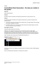
<strong>dSPACE</strong> System<br />
Fuel Cell Emergency Power System (FCEPS)<br />
RapidPro SC Unit<br />
� 14 x pressure<br />
� 5 x throughput<br />
� 4 x temperature<br />
Figure 3: Schematic of the FCEPS and the <strong>dSPACE</strong> system on the test bench. Up to 100 signals are recorded, and then monitored and regulated<br />
with <strong>dSPACE</strong> ControlDesk. This system allows a wide range of scenarios to be tested thoroughly and comprehensively.<br />
fuel cell applications in aircraft. There<br />
are plans to run a fuel cellsystem<br />
non stop to generate all the electricity<br />
required in an aircraft, instead of<br />
using the engines for this as at present.<br />
PC with<br />
ControlDesk<br />
USB USB<br />
� Power electronics and energy storage<br />
� Test bench and system<br />
� Control of coolant pump<br />
� Fuel cell voltage monitor<br />
Oxygen tank Hydrogen tank<br />
Safety valve<br />
Solenoid<br />
Pressure reducer<br />
O 2<br />
128 bar<br />
H 2<br />
350 bar<br />
4 x CAN 5 x analog<br />
Safety valve<br />
Solenoid<br />
Pressure reducer<br />
The waste air from the fuel cell system<br />
could also be used for inerting the<br />
fuel tanks (i.e., preventing explosive<br />
gas mixtures), and the water could<br />
be recycled on board – incidentally<br />
Expansion Box with<br />
DS1005 Processor Board<br />
and various I/O boards<br />
� 1 x thermostat valve<br />
� 2 x pump capacity control<br />
� 2 x pressure control valves<br />
Heat exchanger<br />
Cooling pump<br />
Cooling<br />
Anode<br />
Cathode<br />
RapidPro Power Unit<br />
� 14 solenoid valves<br />
also reducing the quantity of water<br />
carried onboard to save weight.<br />
Dirk Metzler<br />
Liebherr-Aerospace Lindenberg GmbH<br />
Germany<br />
Figure 4: The ControlDesk user interface shows the structure of the FCEPS (see figure 3). Window on left: The oxygen and hydrogen tanks at top<br />
left, the fuel cell in the middle, the heat exchanger and exhaust gas system at bottom right. Center window: The cockpit consists of command<br />
switches for the system, an area for the cooling control, and optical LEDs for indicating status and errors. Two control loops have been implemented<br />
for the cooling circuit, one for the fuel cell’s input temperature and one for its output temperature. Various operating states can be<br />
simulated.<br />
DC<br />
AC<br />
M<br />
Thermostat valve<br />
Purge valve<br />
Purge valve<br />
<strong>dSPACE</strong> <strong>Magazine</strong> 3/<strong>2009</strong> · © <strong>dSPACE</strong> GmbH, Paderborn, Germany · info@dspace.com · www.dspace.com<br />
page 27
page 28<br />
eberSpäCher<br />
Silence<br />
is golden<br />
Active exhaust silencers in vehicles<br />
<strong>dSPACE</strong> <strong>Magazine</strong> 3/<strong>2009</strong> · © <strong>dSPACE</strong> GmbH, Paderborn, Germany · info@dspace.com · www.dspace.com
Noise pollution impairs the quality of<br />
life just as much as any other form of<br />
pollution, but noise cannot always be<br />
avoided. So even as far back as the<br />
1930s, researchers began looking for<br />
ways to cancel it out with antinoise.<br />
The algorithms for active exhaust mufflers<br />
are known, and their advantages<br />
are clear, but to date it is not possible<br />
to produce electronic silencers for<br />
vehicles, except under ideal conditions.<br />
The challenge is to get these silencers<br />
out of the laboratory and onto the road.<br />
<strong>dSPACE</strong> <strong>Magazine</strong> 3/<strong>2009</strong> · © <strong>dSPACE</strong> GmbH, Paderborn, Germany · info@dspace.com · www.dspace.com<br />
page 29
page 30<br />
eberSpäCher<br />
Advantages of Active<br />
Noise Control<br />
n More efficient reduction of<br />
dominant engine orders, so<br />
silencers are smaller<br />
n Lower exhaust backpressure,<br />
resulting in higher engine performance<br />
and in some cases<br />
lower fuel consumption<br />
n Customizable vehicle sound<br />
n Versatile silencer design, meaning<br />
more reusable components<br />
n Simplified development processes<br />
and shorter development times<br />
The purpose of an exhaust system<br />
is not only to lead combustion<br />
exhaust gases away from the vehicle<br />
safely, but to reduce noise emissions<br />
also, i.e., to muffle the<br />
sounds caused by the combustion<br />
process.<br />
Noise<br />
Time (t)<br />
ANC controller produces<br />
the antinoise<br />
Time (t)<br />
Time (t)<br />
Figure 1: Active silencing by antinoise.<br />
The ActiveSilence ® system from<br />
Eberspächer goes further; not only<br />
muffling noise better than anything<br />
before it, but also modifying the<br />
entire sound profile of the vehicle.<br />
The Basic Idea<br />
Using the principle of destructive<br />
interference, a sound source generates<br />
a sound with the same amplitude<br />
and frequency as the unwanted<br />
sound. When the two sounds are<br />
overlaid with a phase shift of precisely<br />
180°, they cancel each other<br />
out. This principle also plays an<br />
important role in active noise control<br />
(ANC) for exhaust systems. The control<br />
works perfectly under idealized laboratory<br />
conditions, but getting it onto<br />
the road is a major challenge. The<br />
ANC system’s components such as<br />
the loudspeaker are very sensitive,<br />
and the exhaust system’s ambient<br />
conditions make it difficult to<br />
Noise and antinoise<br />
cancel each other out<br />
achieve an optimal system. The loudspeaker<br />
and the microphone have to<br />
withstand exhaust temperatures that<br />
range from -30 °C during a cold<br />
start to +700 °C during peak performance,<br />
plus moisture, shocks and<br />
vibrations. The control also has to<br />
handle rapidly changing parameters<br />
such as engine speed and sound<br />
pressure level.<br />
The Control Design<br />
The primary sound components in<br />
an engine’s exhaust system are the<br />
harmonics of the ignition’s frequency,<br />
meaning that combustion engines<br />
can be classified as narrow-band<br />
sound sources. Our studies show<br />
that the most practical approach to<br />
active noise control in this case is an<br />
adaptive narrow-band feedforward<br />
control. The reference signal with<br />
information on the state of the<br />
combustion engine (speed, load)<br />
comes from the engine ECU via<br />
the CAN bus (figure 2). The ANC<br />
controller uses the information to<br />
control the loudspeaker with a 180°<br />
phase shift (feedforward part) and<br />
generate the secondary noise to<br />
cancel out the engine noise. The<br />
microphone picks up the residual<br />
noise, which the ANC then minimizes.<br />
The control requirements are tough:<br />
n Maximum efficiency over the<br />
greatest possible frequency range<br />
to suppress a broad noise spectrum<br />
n Flexibility with regard to installation<br />
so that the system can be used<br />
for various engine families from<br />
different manufacturers<br />
n Adaptivity to varying physical<br />
parameters such as temperature,<br />
vibrations, and shocks<br />
n High robustness and reliability<br />
in all system elements<br />
n Simple control electronics<br />
The ANC controller generates the<br />
secondary noise via a secondary<br />
sound path. The transfer function<br />
between the controller output (control<br />
<strong>dSPACE</strong> <strong>Magazine</strong> 3/<strong>2009</strong> · © <strong>dSPACE</strong> GmbH, Paderborn, Germany · info@dspace.com · www.dspace.com
Figure 2: The control design.<br />
Engine ECU<br />
Combustion engine<br />
Catalytic<br />
converter<br />
ActiveSilence ® (ANC)<br />
controller<br />
CAN PWM<br />
Center muffler/<br />
particulate filter Actuator<br />
Amplifier<br />
“ The MicroAutoBox enabled us to develop a<br />
cost-efficient, integrated solution and to further<br />
optimize the overall system.“ Dr.-Ing. Jan Krüger, Eberspächer<br />
signal) and its error signal input (error<br />
microphone signal) is called the<br />
transfer function of the secondary<br />
sound path (figure 3).<br />
The ANC controller<br />
n Reduces dominant engine orders<br />
in a frequency range of 35-400 Hz<br />
n Increases frequencies selectively<br />
to achieve a target sound<br />
n Identifies the transfer function of<br />
the secondary sound path even<br />
with engine noise<br />
Model-Based Development<br />
Process<br />
In the model-based development<br />
process, various simulations showed<br />
that the control returned the correct<br />
results.<br />
The first step toward practical application<br />
is to implement the ANC<br />
algorithm on a <strong>dSPACE</strong> MicroAuto-<br />
Box used as a prototyping system.<br />
To do this, we simulate the engine<br />
noises by replaying recorded exhaust<br />
noises via a loudspeaker in the laboratory.<br />
This lets us check whether<br />
the controller functions correctly on<br />
the MicroAutoBox. With <strong>dSPACE</strong><br />
ControlDesk, we can adjust and<br />
optimize parameters such as the<br />
necessary filter length of the embedded<br />
controller. At this point, the<br />
MicroAutoBox is ready for use in the<br />
demo vehicle. The ANC controller is<br />
Sensor<br />
D Reconstruc-<br />
Anti-aliasing A<br />
y(n) A tion filter<br />
filter D y’(n)<br />
Secondary sound path<br />
given further reference data such as<br />
engine speed, engine load, and<br />
vehicle speed via the vehicle powertrain<br />
CAN. Using the results of previous<br />
analyses, we study the properties<br />
of the overall system and optimize<br />
its total performance. The dynamic<br />
behavior of the system, particularly<br />
its effect on the criteria for the<br />
transmission function, is investigated<br />
in detail. The MicroAutoBox allows<br />
us to develop and refine an inexpensive<br />
and integrated solution.<br />
The Test Vehicle Setup<br />
We installed the ANC system in<br />
exhaust systems for a 4-cylinder<br />
gasoline engine. The direct injection<br />
system is fitted with a dual exhaust<br />
Figure 3: Transfer function between controller output and error signal input.<br />
<strong>dSPACE</strong> <strong>Magazine</strong> 3/<strong>2009</strong> · © <strong>dSPACE</strong> GmbH, Paderborn, Germany · info@dspace.com · www.dspace.com<br />
page 31
page 32<br />
eberSpäCher<br />
Controller<br />
Transfer<br />
function<br />
Model-based<br />
control design<br />
GT Power<br />
system as standard, so two active<br />
silencers were used to replace the<br />
conventional rear-exhaust silencer.<br />
The active silencer contains a microphone<br />
and loudspeakers that were<br />
specially developed to withstand<br />
the high temperatures and provide<br />
high output performance. All the<br />
other exhaust system elements, such<br />
as the catalyst, remained as they were.<br />
The exhaust system needs other<br />
electronic components in addition<br />
to the conventional silencer<br />
Dr.-Ing. Jan Krüger: Programm Manager<br />
for ActiveSilence ® Technology<br />
In 1999 he completed his doctoral thesis on<br />
active silencers. He has been responsible<br />
for developing exhaust system acoustics<br />
at Eberspächer since 2000.<br />
Rapid prototyping<br />
(demo vehicle)<br />
Implementation<br />
CAN<br />
Identification / modeling<br />
ECU<br />
Operating panel<br />
Figure 4: The development process – from model-based development to integratable control.<br />
system. We used the following in<br />
this project:<br />
n A <strong>dSPACE</strong> MicroAutoBox for realtime<br />
algorithm processing<br />
n An amplifier to control the “canceling”<br />
antinoise loudspeaker with<br />
around 40 W maximum power<br />
n An operating console in the driver’s<br />
cab for setting predefined sound<br />
profiles and monitoring system<br />
status<br />
n A microphone amplifier to return<br />
residual noise to the controller<br />
Results<br />
With more than 50,000 kilometers<br />
driven within 18 months, we were<br />
able to install and test the ANC system<br />
in various vehicles. We found a<br />
considerable reduction in exhaust<br />
About Eberspächer<br />
Integrated solution<br />
(production installation)<br />
noise in every case. Moreover, not<br />
only can the noise be reduced, the<br />
sound can also be improved. This<br />
means that the ANC system can be<br />
adapted to the vehicle, the driving<br />
situation, and the driver’s wishes.<br />
The ANC system’s acoustic performance<br />
was tested on a chassis roll<br />
test bench at full acceleration, with<br />
wide-open throttle (WOT) in third<br />
gear. We adjusted the controller so<br />
that it reduces the dominant engine<br />
orders 2, 4 and 6. The exhaust noise<br />
was measured at a distance of 0.5 m<br />
and at an angle of 45° to the exhaust<br />
tailpipe.<br />
When the ANC system is switched<br />
off, the sound level is around 5 dB(A)<br />
higher than with the standard production<br />
system, because the original<br />
Founded 1865<br />
Headquarters Esslingen am Neckar<br />
Employees 5,575<br />
Turnover € 2,239.9 m (2008)<br />
Products Exhaust technology: catalytic converters, soot filters,<br />
silencers<br />
Auxiliary heating systems for cars, transporters, trucks,<br />
buses, construction machines and boats<br />
<strong>dSPACE</strong> <strong>Magazine</strong> 3/<strong>2009</strong> · © <strong>dSPACE</strong> GmbH, Paderborn, Germany · info@dspace.com · www.dspace.com
passive silencer is no longer present.<br />
With the ANC system switched on,<br />
however, we measured a significant<br />
reduction of 2 to 8 dB(A) compared<br />
with the production system. We<br />
therefore achieved an improvement<br />
in noise levels over almost the entire<br />
engine speed range. The same<br />
measurements were performed for<br />
the 2nd engine order. The positive<br />
effect of the ANC system was clear<br />
here. Reduction started at an engine<br />
speed of 1200 revolutions per minute<br />
(40 Hz), and the noise was reduced<br />
by 10 to 20 dB over a wide range.<br />
Total sound level /dB(A)<br />
110<br />
100<br />
90<br />
80<br />
70<br />
60<br />
110<br />
100<br />
90<br />
80<br />
70<br />
60<br />
2000 30000 4000 5000 6000<br />
Engine speed 1/min<br />
Sound level at 2nd engine order / dB(A)<br />
The noise level was also considerably<br />
reduced with other engine orders,<br />
so the exhaust noise had practically<br />
no additional effect on the noise<br />
level in the vehicle interior. We<br />
demonstrated that – especially in<br />
our demo vehicle – it is possible to<br />
achieve a degree of acoustic comfort<br />
that is otherwise present only<br />
in luxury vehicles.<br />
Dr.-Ing. Jan Krüger<br />
J. Eberspächer GmbH & Co. KG<br />
Esslingen<br />
Germany<br />
Figure 5: Overall sound level for a 4-cylinder gasoline engine (gray = standard production<br />
system, blue = ANC system switched off, red = ANC system switched on).<br />
1000 2000 30000 4000 5000 6000<br />
Engine speed 1/min<br />
Figure 6: Sound level of the 2nd engine order for a 4-cylinder gasoline engine (gray = standard<br />
production system, blue = ANC system switched off, red = ANC system switched on).<br />
Summary<br />
We successfully took the AnC<br />
system out of the laboratory<br />
and put it on the road as the<br />
ActiveSilence ® system. It performed<br />
beyond our expectations,<br />
even under adverse conditions.<br />
We verified all its functional<br />
benefits, such as reducing the<br />
noise, the volume of the silencers,<br />
and the exhaust backpressure.<br />
Our next step will be to reduce<br />
system costs. the system will be<br />
put in production vehicles only<br />
if the additional costs for loudspeakers<br />
and controller hardware<br />
and software can be offset<br />
either by greater functionality<br />
or by some other added value<br />
for the customer.<br />
Glossary<br />
Sound – Gas pressure fluctuations<br />
that consist of a basic frequency<br />
changing over time and its harmonics.<br />
the harmonics determine the characteristic<br />
acoustic impression of a sound.<br />
Engine orders – An engine order<br />
states a frequency (harmonic) in an<br />
engine’s frequency range that is a<br />
multiple of the engine speed. For<br />
example, the 2nd engine order is the<br />
harmonic that corresponds to twice<br />
the engine speed.<br />
<strong>dSPACE</strong> <strong>Magazine</strong> 3/<strong>2009</strong> · © <strong>dSPACE</strong> GmbH, Paderborn, Germany · info@dspace.com · www.dspace.com<br />
page 33
page 34<br />
Delphi DieSel SySteMS<br />
Plug<br />
& Play Various ECUs tested by automated sequences<br />
<strong>dSPACE</strong> <strong>Magazine</strong> 3/<strong>2009</strong> · © <strong>dSPACE</strong> GmbH, Paderborn, Germany · info@dspace.com · www.dspace.com
Delphi Diesel Systems has successfully developed automated integration<br />
and feature tests for various ECUs for diesel engine management systems.<br />
The challenge was to adapt the test system to other ECU versions as<br />
smoothly as possible. A wide range of <strong>dSPACE</strong> software and hardware<br />
offered the seamless tool environment for this task.<br />
<strong>dSPACE</strong> <strong>Magazine</strong> 3/<strong>2009</strong> · © <strong>dSPACE</strong> GmbH, Paderborn, Germany · info@dspace.com · www.dspace.com<br />
page 35
page 36<br />
Delphi DieSel SySteMS<br />
The Challenge<br />
The growing complexity of embedded<br />
controllers for automotive applications<br />
has dramatically increased the<br />
need for HIL (hardware-in-the-loop)<br />
bench testing and validation. ECU<br />
(electronic control unit) software<br />
releases, in fact, have to meet an<br />
ever-increasing number of tough<br />
customer requirements. For this<br />
reason, Delphi Diesel Systems (DDS),<br />
supported by <strong>dSPACE</strong> Ltd., has been<br />
working on developing a series of<br />
HIL-based automated tests to be<br />
utilized with different ECUs for diesel<br />
engine management systems.<br />
HIL-Based Automated Tests<br />
Nowadays, manual ECU testing is<br />
a viable alternative only for a very<br />
limited set of validation tasks. This<br />
explains why every tool vendor has<br />
been working hard to provide<br />
customers with real-time platforms<br />
capable of supporting the development<br />
and execution of automated tests.<br />
<strong>dSPACE</strong> has succeeded in tackling<br />
this problem thanks to Automation-<br />
Desk, which has been playing a crucial<br />
role for many DDS development<br />
activities since early 2008. Apart<br />
from the flowchart-like approach,<br />
which noticeably simplifies both test<br />
design and sequence debugging,<br />
this tool basically has two main advantages:<br />
n AutomationDesk is Python-based.<br />
Consequently, any custom script<br />
or library developed in standard<br />
Python can easily be integrated<br />
into automated tasks. DDS has<br />
already put AutomationDesk pro j-<br />
ects in place that incorporate<br />
ControlDesk macros, third-party<br />
Python modules, such as Pylab<br />
and Matplotlib, and Tkinter-based<br />
GUIs. An example graphical interface<br />
is shown in figure 1. In addi-<br />
“ The interaction of the <strong>dSPACE</strong> tools was very<br />
efficient and saved us a lot of time.”<br />
Figure 1: GUI created with the use of the Python module<br />
Tkinter. These graphical interfaces can be used to configure<br />
AutomationDesk projects.<br />
Giuseppe Raffa, Delphi Diesel Systems<br />
tion to this, DDS has developed its<br />
own Python library to enhance<br />
standardization, code components<br />
reuse and version control in the<br />
development process of new automated<br />
sequences.<br />
n AutomationDesk includes a COM<br />
interface that allows the user to<br />
invoke <strong>dSPACE</strong> ControlDesk (test<br />
and experiment software) MATLAB ®<br />
and, above all, CalDesk, <strong>dSPACE</strong>’s<br />
measurement and calibration software.<br />
No additional code is needed,<br />
as these tools can be called by<br />
means of standard Automation Desk<br />
library blocks. The possibility of<br />
interacting with the <strong>dSPACE</strong> cali-<br />
bration environment CalDesk<br />
(in particular, via CCP on CAN)<br />
proved extremely effective, simply<br />
because the ECU software can be<br />
monitored or re-calibrated while<br />
the sequence is running, with no<br />
other tool necessary.<br />
As a result, all the HIL-based automated<br />
tests developed by DDS have<br />
been implemented using the components<br />
shown in figure 2.<br />
Hardware Set-Up<br />
To maximize the return on investment,<br />
DDS chose a simulator based on<br />
<strong>dSPACE</strong> double mid-size configuration<br />
(figure 3). Being an off-the-shelf<br />
product, this platform allowed the<br />
company to reduce initial costs without<br />
any significant performance<br />
limitation.<br />
Thanks to the open architecture of<br />
the double mid-size system, which<br />
incorporates a DS1005 processor<br />
board and a DS2211/DS2202 pair<br />
of HIL boards, DDS achieved the<br />
following results:<br />
n Easy management and support of<br />
different ECU configurations. A<br />
simulator is connected with the<br />
<strong>dSPACE</strong> <strong>Magazine</strong> 3/<strong>2009</strong> · © <strong>dSPACE</strong> GmbH, Paderborn, Germany · info@dspace.com · www.dspace.com
embedded controller via an ECUspecific<br />
test harness that features<br />
a standardized structure. Consequently,<br />
when the HIL simulator<br />
has to be used for a different<br />
project, a suitable interface loom<br />
is needed. However, since this installation<br />
takes minutes, the chosen<br />
platform significantly increases the<br />
bench uptime.<br />
n The majority of the ECU pins are<br />
always assigned to DS2211 channels.<br />
In fact, in comparison to the<br />
DS2202, this HIL I/O board is<br />
equipped with an angular processing<br />
unit (APU). This design solution<br />
automatically frees up many<br />
channels on the DS2202 that are<br />
currently exploited to drive additional<br />
boards and controllers<br />
which need to be interfaced with<br />
the main ECU.<br />
Adapting the HIL simulator for future<br />
projects will require relatively little<br />
effort. A new harness will have to be<br />
designed, but this can be done in<br />
such a way that a certain ECU func-<br />
Figure 3: Double <strong>dSPACE</strong> Simulator Mid-Size.<br />
Python standard<br />
modules<br />
(math, Tkinter ...)<br />
DELPHI Python<br />
library<br />
(post-processing)<br />
Python non<br />
standard modules<br />
(pylab, matplotlib ...)<br />
AutomationDesk<br />
COM Interface<br />
(CalDesk & ControlDesk)<br />
AutomationDesk framework<br />
Figure 2: Components used by DDS to implement HIL-based tests. They can be integrated<br />
into AutomationDesk sequences.<br />
tionality will always be mapped to<br />
the same simulator channel. With<br />
this in mind, the platform configuration<br />
can undoubtedly be simplified.<br />
CPU Load Evaluation<br />
Thanks to the architecture described<br />
above, DDS has developed automated<br />
test sequences for both integration<br />
and feature tests. Among<br />
them, the CPU load test is one of<br />
the most interesting. Quantifying<br />
the CPU usage when the controller<br />
receives a variety of stimuli is the key<br />
to assessing whether a given hardware-software<br />
integration actually<br />
meets the initial requirements and<br />
what margins may be available to<br />
further developments.<br />
As shown in figure 4, AutomationDesk<br />
Glossary<br />
Tkinter – Standard module used to<br />
create object-oriented GUIs in Python:<br />
For more information see M. Lutz,<br />
“Programming Python”, 3rd edition<br />
published by O’Reilly.<br />
Matplotlib – Python plotting library<br />
for creating 2D figures.<br />
For more information see<br />
www.matplotlib.sourceforge.net<br />
<strong>dSPACE</strong> <strong>Magazine</strong> 3/<strong>2009</strong> · © <strong>dSPACE</strong> GmbH, Paderborn, Germany · info@dspace.com · www.dspace.com<br />
page 37
page 38<br />
Delphi DieSel SySteMS<br />
Worst case<br />
scenario cycle<br />
enabled DDS to implement an automated<br />
sequence that stimulates the<br />
embedded controller according to<br />
selected worst-case scenarios. The<br />
ECU software includes a function<br />
measuring the CPU load in terms of<br />
percentage of main cycle time spent<br />
on required tasks; the results are<br />
made available to calibration tools<br />
through a series of measurement<br />
parameters that can be used to evaluate<br />
the average CPU load in each<br />
test condition. To generate a testing<br />
report, these parameters are finally<br />
post-processed in such a way that<br />
they are displayed as a function of<br />
the received stimuli.<br />
Endurance Test Implementation<br />
DDS has always been focused on<br />
safety and reliability. Consequently,<br />
a set of automated sequences that<br />
aim at coping with possible endurance-related<br />
problems have been<br />
ECU calibration upload<br />
Finished? No<br />
Yes<br />
Figure 4: CPU load test developed by DDS.<br />
Stimuli calculation<br />
and generation<br />
with AutomationDesk<br />
CPU load / stack<br />
lenght evaluation<br />
on the ECU<br />
Data acquisition<br />
with CalDesk<br />
Test report generation<br />
with AutomationDesk<br />
designed. The principle underlying<br />
this group of tests consists of creating<br />
faulty conditions on the ECU<br />
physical interface to evaluate the<br />
robustness of the controller both<br />
from the hardware and the software<br />
point of view.<br />
An example of these tests is summarized<br />
in figure 5. Cutting off the<br />
battery voltage repeatedly while the<br />
controller is operating is an effective<br />
way of testing how the ECU nonvolatile<br />
memory responds. A<br />
sequence of this kind, which can<br />
be executed hundreds of times overnight,<br />
can quickly be implemented<br />
by driving the power supplies included<br />
in the simulator according to<br />
predefined cycles.<br />
Future Development<br />
Several AutomationDesk-related<br />
development activities are going on<br />
at DDS. The currently available HILbased<br />
sequences need to be improved<br />
to incorporate a wider range<br />
of configuration parameters and<br />
facilitate their execution. Furthermore,<br />
more comprehensive integration<br />
tests will certainly be created to deal<br />
with potential problems arising from<br />
new ECU functions and automatically<br />
generated code.<br />
More precisely:<br />
n Other software performance<br />
metrics will have to be taken into<br />
account as well. For instance,<br />
a variant of the CPU load test<br />
sequence implementing a stack<br />
size measurement is now available.<br />
“ Thanks to the <strong>dSPACE</strong> HIL architecture, adapting<br />
the test system for future projects will require<br />
relatively little effort.”<br />
Riccardo Carrozzo, Delphi Diesel Systems<br />
n Integrating GUIs into Automation-<br />
Desk projects is a key priority, in<br />
order to build a user-friendly testprocess<br />
management environment.<br />
This can be used effectively to<br />
configure and launch the desired<br />
set of test sequences, without<br />
requiring a developer-level knowledge<br />
of AutomationDesk.<br />
n A combined sequence to evaluate<br />
injection management and rail<br />
pressure control performances is<br />
currently under study. The final<br />
target consists of creating a<br />
complete set of automated test<br />
sequences that will be executed<br />
<strong>dSPACE</strong> <strong>Magazine</strong> 3/<strong>2009</strong> · © <strong>dSPACE</strong> GmbH, Paderborn, Germany · info@dspace.com · www.dspace.com
as a standard HIL bench validation<br />
before starting any in-vehicle validation<br />
activity.<br />
Conclusion<br />
AutomationDesk has enabled DDS<br />
to develop a variety of automated<br />
tests, which have been shared across<br />
different ECU projects. In fact, this<br />
<strong>dSPACE</strong> tool, with its wide set of<br />
Endurance<br />
cycle<br />
ECU calibration<br />
upload<br />
Battery voltage<br />
& ECU on<br />
Battery voltage Off<br />
while ECU is on<br />
Finished?<br />
Figure 5: Endurance test developed by DDS.<br />
ECU condition<br />
analysis<br />
Test report<br />
generation<br />
built-in block libraries, has allowed<br />
developers to interface seamlessly<br />
with calibration tools, such as<br />
CalDesk, and with the real-time HIL<br />
simulator. Moreover, integrating<br />
customized, standard and third-party<br />
Python modules has significantly<br />
facilitated the final data post-processing,<br />
thus guaranteeing highquality<br />
test reports.<br />
Yes<br />
No<br />
Riccardo Carrozzo (left) –<br />
HIL Team Manager. He coordinates activities<br />
focused on modelling and HIL validation.<br />
Giuseppe Raffa (center) –<br />
Principal System Engineer. He designs HIL /<br />
ECU interface harnesses and develops automated<br />
tests for embedded controllers.<br />
Darren Walker (right) –<br />
Core Software Manager. He is responsible for<br />
core software engineering, encompassing<br />
ECU platform software, and associated tools<br />
and processes.<br />
The reusability of these automated<br />
sequences has been improved even<br />
further thanks to the openness of<br />
the selected hardware platform,<br />
namely the <strong>dSPACE</strong> mid-size HIL<br />
simulator. In fact, every time the<br />
bench has to be switched to a<br />
different controller, only a suitable<br />
interface harness has to be installed.<br />
Two real examples of HIL-based<br />
automated sequences are finally<br />
presented. They illustrate not only<br />
the effectiveness of integrating<br />
AutomationDesk and CalDesk, but<br />
also how DDS intends to improve<br />
the quality and reliability of its<br />
embedded controllers.<br />
Riccardo Carrozzo, Giuseppe Raffa,<br />
Darren Walker<br />
Delphi Diesel Systems<br />
United Kingdom<br />
<strong>dSPACE</strong> <strong>Magazine</strong> 3/<strong>2009</strong> · © <strong>dSPACE</strong> GmbH, Paderborn, Germany · info@dspace.com · www.dspace.com<br />
page 39
page 40<br />
DS5203 Fpga boarD<br />
Speed and Flexibility<br />
applications with extremely short<br />
latencies and cycle times FPGAFor<br />
Tougher laws on emissions and fuel consumption make new drive concepts<br />
with highly sophisticated sensor systems a necessity. This also affects<br />
rapid control prototyping (RCP) and hardware-in-the-loop (HIL) simulation.<br />
To help meet these tougher requirements, <strong>dSPACE</strong> has produced its new<br />
DS5203 FPGA Board. Installed directly on the I/O interface, the board can<br />
be programmed any way you like. It is an invaluable assistant that not only<br />
performs signal conditioning, but also calculates models that require high<br />
dynamics.<br />
<strong>dSPACE</strong> <strong>Magazine</strong> 3/<strong>2009</strong> · © <strong>dSPACE</strong> GmbH, Paderborn, Germany · info@dspace.com · www.dspace.com
FPGAs for Versatility<br />
Field-programmable gate arrays<br />
(FPGAs) are programmable logic<br />
circuits. Essentially, they are programmed<br />
by combining and connecting<br />
their logic elements and<br />
memory cells in many different<br />
ways. Each logic element consists<br />
of a programmable truth table<br />
(look-up table, LUT) with 4-6 inputs,<br />
one output, and one flip-flop (1-bit<br />
register) for directly representing<br />
simple logical operations (AND, OR,<br />
etc.) To implement complex digital<br />
signal processing algorithms such as<br />
FFTs or even entire embedded microcontroller<br />
cores, several logic elements<br />
are used together.<br />
The FPGA architecture supports<br />
genuine parallel processing,<br />
achieved by inserting hardware<br />
blocks multiple times. The hardware<br />
functions, and their interconnections<br />
via the FPGA’s logic cells, are<br />
described in a hardware description<br />
language such as VHDL. This allows<br />
an FPGA’s behavior to be described<br />
in text form without its structure<br />
having to be known. The FPGA<br />
manufacturer supplies a tool called<br />
a synthesis tool that generates the<br />
FPGA’s actual configuration.<br />
Graphical Programming: Straight<br />
from Simulink ® Model to FPGA<br />
The most convenient way to configure<br />
an FPGA is graphical modeling, for<br />
instance with the Xilinx ® System<br />
Generator (XSG), a Simulink ® blockset<br />
for configuring Xilinx FPGAs. The<br />
XSG contains simple logic elements<br />
and complex blocks such as Fourier<br />
transforms and FIR filters. <strong>dSPACE</strong><br />
provides both the hardware<br />
(DS5203 FPGA Board) and the software<br />
(RTI FPGA Programming Blockset)<br />
to connect the XSG models to<br />
the FPGA’s interfaces.<br />
The DS5203 FPGA Board contains a<br />
programmable Virtex ® 5 Xilinx FPGA<br />
and preconfigured I/O driver components.<br />
The RTI FPGA Programming<br />
Blockset is a convenient way to<br />
connect the I/O board’s I/O driver<br />
components and to model the connection<br />
to a processor board, so<br />
processor boards (such as <strong>dSPACE</strong>’s<br />
DS1006 used as the central board<br />
Field-programmable gate arrays (FPGAs) consist of a large number of logic elements that can be<br />
interconnected flexibly. This makes FPGAs useful for an extremely wide range of applications.<br />
for calculating complex models) can<br />
be connected to the FPGA quickly<br />
and simply. Thus, FPGA programming<br />
is seamlessly integrated into<br />
the Simulink environment, which<br />
the user already knows from working<br />
with <strong>dSPACE</strong>’s prototyping or<br />
hardware-in-the-loop systems.<br />
When the FPGA board is used, the<br />
synthesis, build, and programming<br />
of the FPGA or processor can be run<br />
directly from Simulink for optimal<br />
convenience.<br />
Further Requirements for<br />
Programming<br />
In the synthesis process, each<br />
function and each model block is<br />
individually mapped to dedicated<br />
hardware and requires space on the<br />
FPGA. Since floating-point data<br />
types consume an extremely high<br />
amount of resources, only operators<br />
for fixed-point data types can be<br />
run usefully on today’s FPGAs.<br />
To achieve a reasonable compromise<br />
between precision and space requirement,<br />
it helps when an FPGA expert<br />
supports the model developer in<br />
defining the bit widths of different<br />
functions. The FPGA expert also<br />
helps in optimizing FPGA-specific<br />
properties such as signal execution<br />
times and the timing of switching.<br />
Offline simulation or joint simulation<br />
of the Simulink model and the<br />
VHDL code helps developers identify<br />
any problems before implementation<br />
on the actual FPGA.<br />
Because of these requirements, an<br />
FPGA expert will probably support<br />
the software developer responsible<br />
for modeling if a function has to be<br />
implemented on an FPGA. Either<br />
the two of them work together and<br />
run joint simulations of their intermediate<br />
results, or the FPGA expert<br />
solves the FPGA tasks first and then<br />
passes the solution on to the soft-<br />
<strong>dSPACE</strong> <strong>Magazine</strong> 3/<strong>2009</strong> · © <strong>dSPACE</strong> GmbH, Paderborn, Germany · info@dspace.com · www.dspace.com<br />
page 41
page 42<br />
DS5203 Fpga boarD<br />
Simulink model with XSG blocks for the DS5203 FPGA Board: a PI controller as an example.<br />
ware developer. The result is a<br />
growing pool of solutions that can<br />
be reused for future tasks.<br />
FPGAs in Use<br />
The core of a <strong>dSPACE</strong> system is the<br />
processor board. If the processor<br />
board cannot calculate a model in<br />
the necessary cycle time, a part of<br />
the model has to be moved out to<br />
an FPGA.<br />
Even though an FPGA has a considerably<br />
slower clock rate (the DS5203<br />
has 100 MHz) than a processor (the<br />
DS1006 Processor Board has 3 GHz),<br />
it can solve numerous tasks faster.<br />
This is because its logic elements<br />
work in parallel, and this often more<br />
than compensates for the lower<br />
clock rate. Moreover, the FPGA on<br />
the DS5203 is connected to the I/O<br />
directly, so the entire bandwidth of<br />
converters can be used with minimum<br />
latencies, and very fast control loops<br />
can be implemented. This is increasingly<br />
an issue in the development of<br />
automotive ECUs, which always<br />
have more requirements for fast,<br />
complex, and highly reactive control<br />
circuits for reducing emissions and<br />
consumption. Cylinder pressurebased<br />
control and knock analysis,<br />
for example, are two applications<br />
fields that demand powerful signal<br />
conditioning. The potential of an<br />
FPGA is ideal for these.<br />
Great Advantages for Electrified<br />
Powertrains<br />
Powertrain electrification is fast<br />
gaining ground as a means to reduce<br />
fuel consumption. Mechanically<br />
coupled auxiliary aggregates (such<br />
as hydraulics and cooling water<br />
pumps) are being replaced by electrical<br />
aggregates that run as and<br />
when required and need no energy<br />
otherwise. To develop controllers for<br />
these electric drives, different interfaces<br />
need to be served flexibly.<br />
They include interfaces for position<br />
The new DS5203 FPGA Board.<br />
sensors such as resolvers and encoders,<br />
and also for addressing power stages<br />
for block and sine commutation.<br />
When ECU tests are run on an HIL<br />
simulator, parts of the electric drive<br />
model have to be implemented on<br />
the FPGA. Otherwise, the high<br />
dynamics requirements cannot be<br />
met. In electric drives, the ECU<br />
controls the power flow directly,<br />
usually at 20 kHz. Modeling the<br />
highly dynamic effects at the power<br />
stages with sufficient precision<br />
requires cycle times considerably<br />
lower than one microsecond. This<br />
can only be achieved by using FPGAs,<br />
with at least the motor current calculation<br />
running on an FPGA board.<br />
Technical Details of the DS5203<br />
In contrast to the DS5202 FPGA<br />
Base Board, which provides an I/O<br />
configuration that is precisely tailored<br />
to a specific application, the<br />
new DS5203 is freely programmable<br />
and can be flexibly adjusted to a<br />
wide range of different scenarios.<br />
The DS5203 has a very powerful<br />
FPGA, the Xilinx Virtex-5 SX95<br />
FPGA, with 94,298 logic cells and<br />
640 special DSP blocks. The DSP<br />
blocks include fast, resource-saving<br />
multiplication of two signals.<br />
For connecting external sensors and<br />
actuators, the DS5203 provides 6 ADC,<br />
<strong>dSPACE</strong> <strong>Magazine</strong> 3/<strong>2009</strong> · © <strong>dSPACE</strong> GmbH, Paderborn, Germany · info@dspace.com · www.dspace.com
Profile of the DS5203<br />
Type: FPGA board freely programmable via Simulink blockset<br />
FPGA: Xilinx Virtex-5 SX95, 100 MHz<br />
I/O: 6 ADC, 6 DAC (14-bit, 10 MSPC), and 16 digital channels, extendable<br />
Bus: <strong>dSPACE</strong> PHS++<br />
6 DAC (14-bit, 10 MSPS), and<br />
16 digital I/O channels.<br />
The number of I/O channels can be<br />
increased by a plug-on module if<br />
required.<br />
Connection to the processor board<br />
is done as usual via the PHS bus.<br />
Interview<br />
With Jürgen Klahold,<br />
Product Engineer for Hardware-in-the-Loop<br />
Simulators,<br />
<strong>dSPACE</strong> GmbH<br />
The FPGA’s 100-MHz clock rate<br />
lets even demanding tasks be<br />
implemented with very short cycle<br />
times.<br />
Mr. Klahold, please tell us some<br />
typical applications for <strong>dSPACE</strong>‘s<br />
new DS5203 FPGA Board.<br />
With the electrification of powertrains,<br />
highly dynamic electric drives<br />
are being used in vehicles more often.<br />
Developing the necessary ECUs<br />
presents particular challenges, in<br />
prototyping and in HIL testing. The<br />
DS5203 provides the right solutions<br />
for this.<br />
But it also opens up new potential<br />
for extended signal analyses, such<br />
as those needed for modern knock<br />
control.<br />
What functions can the DS5203<br />
perform, especially in testing these<br />
applications?<br />
The high dynamics of electric drives<br />
demand simulation with a very short<br />
cycle time. If the effects of power<br />
stages also have to be included, cycle<br />
times far below one microsecond<br />
must be achieved. This is not possible<br />
unless at least a part of the controlled<br />
system‘s model – like the coil model –<br />
is moved out to an FPGA.<br />
Summary<br />
Programming the DS5203 FPGA<br />
Board with the RTI FPGA Programming<br />
Blockset and the Xilinx<br />
System Generator is a good way<br />
to consistently develop a processor<br />
application and an FPGA application<br />
together from Simulink.<br />
The interaction between the two<br />
applications can be tested in offline<br />
simulation before they are<br />
loaded to the real-time system.<br />
Thus, users can react flexibly and<br />
quickly to tougher requirements -<br />
for example, for signal conditioning,<br />
using new interfaces, or<br />
speeding up model parts.<br />
Limited availability outside of Europe<br />
and Asia, please inquire.<br />
What are the strengths and<br />
advantages of the board?<br />
The FPGA Board can be programmed<br />
directly from Simulink ® ,<br />
so it integrates seamlessly into the<br />
familiar tool chain. It has a powerful<br />
FPGA and extensive I/O interfaces<br />
on the actual board. If these<br />
are not enough, more interfaces<br />
can be added by means of a plugon<br />
module.<br />
How do users benefit from<br />
using the board?<br />
Users can create applications that<br />
access the board‘s I/O directly and<br />
with virtually no latencies, so they<br />
can utilize the entire bandwidth of<br />
the signal converters. This lets<br />
them close control loops with very<br />
short cycle times, and also implement<br />
new interfaces.<br />
Thank you for talking to us,<br />
Mr. Klahold.<br />
<strong>dSPACE</strong> <strong>Magazine</strong> 3/<strong>2009</strong> · © <strong>dSPACE</strong> GmbH, Paderborn, Germany · info@dspace.com · www.dspace.com<br />
page 43
page 44<br />
hil api<br />
Platform Independence<br />
Thanks to New Standard<br />
Standardized HIL API enables platform-independent HIL tests<br />
Up to now, a lot of work was necessary to use existing tests on any HIL<br />
simulator. With the new ASAM standard, HIL API, this is much easier.<br />
The HIL API is a standardized interface to connect test automation tools<br />
like AutomationDesk to any kind of HIL system. The result is that the test<br />
automation software has a higher level of investment protection.<br />
What Does HIL API Mean?<br />
API stands for application programming<br />
interface. The HIL API is a standardized<br />
interface that enables users<br />
to access HIL simulators according to<br />
a standardized method. Now, when<br />
using the HIL API, they find it easier<br />
to connect test automation tools<br />
such as <strong>dSPACE</strong> AutomationDesk<br />
to any kind of HIL simulator.<br />
Why Does this Standard Exist?<br />
The testing departments at numerous<br />
OEMs and suppliers have<br />
recently been asking <strong>dSPACE</strong> for<br />
one single test automation tool for<br />
accessing HIL simulators from different<br />
suppliers. The advantages<br />
were obvious: Only one software<br />
tool needs to be purchased,<br />
test engineers only need to be trained<br />
for one tool, and libraries are developed<br />
and maintained for just one<br />
single tool. In addition, the software’s<br />
independence from the HIL<br />
simulator guarantees that the software<br />
has a high level of investment<br />
protection.<br />
<strong>dSPACE</strong> therefore set up a workgroup<br />
with the goal of standardizing the<br />
access to HIL simulators. Various OEMs,<br />
<strong>dSPACE</strong> <strong>Magazine</strong> 3/<strong>2009</strong> · © <strong>dSPACE</strong> GmbH, Paderborn, Germany · info@dspace.com · www.dspace.com
suppliers and tool manufacturers sat<br />
together with the leading spokesman,<br />
Dr. Jobst Richert (<strong>dSPACE</strong> GmbH), to<br />
define the standard. In July <strong>2009</strong>,<br />
ASAM (Association for Standardisation<br />
of Automation and Measuring<br />
Systems) officially adopted this<br />
standard, named as HIL API.<br />
What Was Standardized?<br />
Not only was the access to HIL simulators<br />
standardized, but also the<br />
access to electronic control units<br />
(ECUs). The HIL API is divided into<br />
the following areas:<br />
n Access to HIL simulators<br />
n Access to ECUs during measurement<br />
and calibration<br />
n Access to diagnostics<br />
n Electrical failure simulation<br />
How Do Users Benefit?<br />
To develop ECU tests independently<br />
of HIL systems, test engineers<br />
previously needed to pay attention<br />
to defining and using abstraction<br />
layers when developing these tests.<br />
If they neglected to do so, they had<br />
AutomationDesk<br />
to perform numerous adaptations to<br />
use the tests on a HIL simulator from<br />
another supplier. The HIL API makes<br />
the platform-independent development<br />
of tests development much<br />
easier: A HIL API-based test can be<br />
executed on another HIL system<br />
without any problems – provided<br />
that a HIL API interface was implemented<br />
for the other HIL simulator.<br />
It makes no difference if users already<br />
have HIL simulators from different<br />
manufacturers, or simply do not want<br />
to decide on just one manufacturer.<br />
With the HIL API, just a click is enough<br />
to use test sequences on different<br />
simulation hardware.<br />
If their test automation tool already<br />
supports the HIL API, they are on the<br />
safe side and attain a high investment<br />
protection for their test software.<br />
<strong>dSPACE</strong> will implement the HIL API<br />
for its HIL simulators and will adapt<br />
the test automation software<br />
Auto mationDesk accordingly for the<br />
HIL API. Parts of the standard will be<br />
implemented as early as in the upcoming<br />
version of AutomationDesk<br />
(fall <strong>2009</strong>). As a result, AutomationDesk<br />
Using the HIL API in test automation leads to hardware independence.<br />
users can benefit from the new<br />
standard’s advantages right from the<br />
start. For more precise information<br />
on the release date for Automation-<br />
Desk 3.0, visit the <strong>dSPACE</strong> website.<br />
How Does Hardware Replacement<br />
Work?<br />
To reuse test sequences on different<br />
simulation hardware, all users have<br />
to do is to replace the underlying HIL<br />
API library. All manufacturers of<br />
simu lation hardware that support<br />
the HIL API standard will provide the<br />
necessary library with the hardware.<br />
Users just have to click a button in<br />
AutomationDesk to specify which<br />
HIL API library they want to use, which<br />
will also determine the simulation<br />
hardware the tests will run on.<br />
What’s the Outlook?<br />
In the future, the HIL API will be<br />
expanded in Version 2.0. For example,<br />
access to bus systems will be standard<br />
ized. In addition, a further<br />
workgroup is currently working<br />
on standardizing a test exchange<br />
format. This will enable users to<br />
exchange the tests they created in<br />
Automation Desk with other testing<br />
tools, or use tests in AutomationDesk<br />
that were created with a different<br />
tool.<br />
3 rd party HIL simulator<br />
<strong>dSPACE</strong> <strong>Magazine</strong> 3/<strong>2009</strong> · © <strong>dSPACE</strong> GmbH, Paderborn, Germany · info@dspace.com · www.dspace.com<br />
page 45
page 46<br />
rti autoSar paCkage<br />
AUTOSAR<br />
The AUTOSAR standard is increasingly being applied in the early prototyping<br />
and test phases, not just in developing production components. The new<br />
RTI AUTOSAR Package from <strong>dSPACE</strong> makes it easy to integrate AUTOSAR<br />
software components and compositions into the MATLAB ® /Simulink ®<br />
environment and execute them on <strong>dSPACE</strong> real-time hardware.<br />
A Powerful Package<br />
The new RTI AUTOSAR Package<br />
gives embedded software developers<br />
a fast, convenient method to integrate<br />
AUTOSAR components from<br />
different sources (SystemDesk,<br />
TargetLink, handcode) into the<br />
MATLAB ® /Simulink ® environment,<br />
combine them with other Simulink<br />
blocks, and simulate them on a PC.<br />
The components can be executed<br />
on the <strong>dSPACE</strong> real-time hardware<br />
RTI AUTOSAR Package 1.0<br />
Now Boosts Rapid Prototyping and HIL<br />
using Real-Time Interface (RTI) in the<br />
usual way. This provides an enormous<br />
range of opportunities. For example,<br />
when new control functions are<br />
being developed in MATLAB/<br />
Simulink, they can be linked with<br />
existing AUTOSAR components and<br />
tested together with them. Moreover,<br />
new AUTOSAR components<br />
can be quickly loaded to the<br />
<strong>dSPACE</strong> prototyping hardware components<br />
with the RTI AUTOSAR<br />
Package to perform tests in the<br />
actual vehicle. For hardware-in-theloop<br />
(HIL) test scenarios, AUTOSARcompliant<br />
software components<br />
can be implemented on application<br />
level as soft ECUs on <strong>dSPACE</strong> HIL<br />
simulators.<br />
Behind the Scenes<br />
As part of the of the RTI AUTOSAR<br />
Package, the RTI AUTOSAR Interface<br />
Generator is the user’s “first<br />
<strong>dSPACE</strong> <strong>Magazine</strong> 3/<strong>2009</strong> · © <strong>dSPACE</strong> GmbH, Paderborn, Germany · info@dspace.com · www.dspace.com
Work in the familiar MATLAB/Simulink environment: Import AUTOSAR software components, and combine them with Simulink and RTI blocks.<br />
contact” with the AUTOSAR software<br />
components and its associated C<br />
source files. With just a few clicks,<br />
it generates an RTI SWC container<br />
holding the imported components,<br />
already prepared for Simulink. It can<br />
also be automated via a command<br />
line interface. The RTI SWC con-<br />
Workflow<br />
steps:<br />
Related<br />
<strong>dSPACE</strong><br />
tools:<br />
Component<br />
development<br />
� SystemDesk<br />
� TargetLink<br />
� Third-party<br />
tools<br />
� Manual<br />
programming<br />
Generating<br />
Simulink<br />
adaptation for<br />
AUTOSAR<br />
SWCs<br />
RTI AUTOSAR<br />
Interface<br />
Generator<br />
tainer can be loaded to MATLAB/<br />
Simulink via the RTI AUTOSAR Interface<br />
Blockset. The generated blocks<br />
represent the specific behavior and<br />
the interfaces of the original<br />
AUTOSAR software components.<br />
To help you get started, the RTI<br />
AUTOSAR Package contains a<br />
Creating<br />
an AUTOSAR<br />
block<br />
RTI AUTOSAR<br />
Interface Blockset<br />
PC-based<br />
simulation<br />
descriptive, easily expandable<br />
demonstration example, which you<br />
can use as the basis for further<br />
projects.<br />
Implementation<br />
and<br />
simulation<br />
on <strong>dSPACE</strong><br />
real-time<br />
hardware<br />
Real-Time<br />
Interface (RTI)<br />
Workflow: With the RTI AUTOSAR Package, it is just a few short steps from AUTOSAR file import to Simulink integration, PC-based<br />
simulation, and implementation and simulation on the <strong>dSPACE</strong> real-time platform.<br />
<strong>dSPACE</strong> <strong>Magazine</strong> 3/<strong>2009</strong> · © <strong>dSPACE</strong> GmbH, Paderborn, Germany · info@dspace.com · www.dspace.com<br />
page 47
page 48<br />
eMh SolutioN<br />
All<br />
EMH Solution – New integrated HIL simulation<br />
of electric motors<br />
Under One Roof<br />
<strong>dSPACE</strong> <strong>Magazine</strong> 3/<strong>2009</strong> · © <strong>dSPACE</strong> GmbH, Paderborn, Germany · info@dspace.com · www.dspace.com
For HIL simulation of electric motors, numerous<br />
inputs and outputs are necessary for the control<br />
variables and sensor signals. <strong>dSPACE</strong> now offers<br />
an integrated FPGA-based solution that combines<br />
all of the essential I/O functions on just one board.<br />
There are currently many control<br />
system interfaces available to connect<br />
hardware-in-the-loop (HIL) systems<br />
to the ECU of an electric motor. For<br />
low-performance motors, i.e. for<br />
electric steering, the electrical performance<br />
level of the ECU or the<br />
mechanical level is often suitable<br />
as an interface to the HIL system.<br />
However, for drive motors of hybrid<br />
vehicles and electric vehicles, the<br />
signal level is the preferred choice;<br />
especially when emphasis is placed<br />
on testing the ECU software and<br />
when operating the power stage<br />
is not necessary.<br />
Simulating a 3-Phase Motor and<br />
Service Calls at Signal Level<br />
When simulating at the signal level,<br />
the power electronics is removed,<br />
and only the signal processing portion<br />
of the ECU are connected to the<br />
simulator. The control signals of the<br />
power switch of the inverter stage<br />
are read in by the simulator and<br />
serve as the basis for the real-time<br />
simulation of the power electronics<br />
and electric motor. To close the control<br />
loop in the HIL simulation, the<br />
simulator must calculate the sensor<br />
signals for the rotor position and<br />
the motor voltages. <strong>dSPACE</strong>’s product<br />
range has long included special<br />
boards for this connection at signal<br />
level, for creating and measuring<br />
PWM signals (pulse width modulation)<br />
and PSS signals (position<br />
sensor simulation).<br />
New Integrated I/O Solution<br />
For the first time ever, the new electric<br />
motor HIL (EMH) solution, based<br />
on the <strong>dSPACE</strong> DS5202 FPGA Board,<br />
offers several necessary I/O channels<br />
to simulate up to two electric motors<br />
“under one roof.” This gives users a<br />
compact, cost-effective way to start<br />
working with the HIL simulation of<br />
electric motors.<br />
Highly Precise PWM Signal<br />
Measurement<br />
To simulate a B6 inverter stage,<br />
for example, measurement of the<br />
6 gate control signals of the ECU<br />
(figure 2) must be highly precise.<br />
With the EMH solution, measure-<br />
<strong>dSPACE</strong> <strong>Magazine</strong> 3/<strong>2009</strong> · © <strong>dSPACE</strong> GmbH, Paderborn, Germany · info@dspace.com · www.dspace.com<br />
page 49
page 50<br />
eMh SolutioN<br />
ECU<br />
Electricmotor<br />
ontrol<br />
Current signal<br />
Power<br />
converter<br />
3-phase<br />
voltage<br />
Application<br />
Position signal<br />
controller Sensor signals<br />
Transmission<br />
Vehicle<br />
application<br />
Controller Power stage Electric motor Mechanics<br />
Figure 1: Interfaces for electric motor simulation.<br />
ment is done at a time resolution<br />
of 25 ns. At defined sampling<br />
times, the duty cycle, period times<br />
and power-up times of individual<br />
signals, as well as the dead times<br />
between neighboring signals are<br />
determined in a bridge arm, and<br />
made available for the real-time<br />
model on the processor of the HIL<br />
simulators (i.e., a DS1006 Processor<br />
Board). The EMH solution usually<br />
determines the sampling times<br />
independently at the middle of the<br />
PWM period, whereby an interrupt<br />
is triggered on the processor,<br />
depending on the operating mode,<br />
so that the model of the power<br />
electronics of the electric motor is<br />
Glossary<br />
B6 inverter – Inverter with a switch<br />
bridge of 6 switch elements for<br />
3-phase alternating current.<br />
SSI (synchronous-serial interface) –<br />
Standard for protocol-based incremental<br />
encoder. Other variants are<br />
Hiperface and EnDat.<br />
Signal level Electric power level Mechanical level<br />
The EMH solution combines all necessary<br />
I/O functions for electric motor simulation –<br />
compact, high-performance, cost-effective.<br />
calculated synchronously with the<br />
PWM frequency. This avoids any<br />
beats. During this, the oversampling<br />
and the downsampling can be<br />
modified. Depending on the PWM<br />
frequency, the sampling times lie<br />
between approx. 30-60 µs. With the<br />
16 channels of the EMH board, all<br />
the gate signals for two 3-phase<br />
electric motors can be read in.<br />
Simulating the Position Sensor<br />
Signals<br />
Because the control of electric motors<br />
must have an exact rotor angle<br />
position to control the voltage and<br />
calculate the speed, this must be<br />
simulated by the HIL system at a<br />
high resolution. The position sensor<br />
simulation offered by the EMH solution<br />
is based on the proven angle<br />
processing unit (APU) principle,<br />
which is already reliably used with<br />
the DS2211 HIL I/O Board. The EMH<br />
board has 4 independent APUs<br />
(figure 3), which users can allocate<br />
to different sensor simulation channels.<br />
This flexibility enables, for example,<br />
the simulation of two electric motors<br />
with independent or independent axles.<br />
The EMH solution offers:<br />
n An analog sensor simulation<br />
group with 3 analog outputs to<br />
simulate resolver, sine encoder, or<br />
analog user-defined signals<br />
n A digital sensor simulation group<br />
with 3 digital outputs to simulate<br />
incremental encoders, Hall sensors<br />
or digital user-defined signals<br />
n 3 further independently usable<br />
digital outputs<br />
All analog signals are resolved at<br />
100 ns, all digital signals at 25 ns.<br />
Because the board contains comprehensive<br />
signal conditioning, an<br />
electric motor ECU can be connected<br />
directly at signal level.<br />
With the universal RS485 UART<br />
interface, many different protocols<br />
can be implemented. In addition to<br />
the TwinSync protocol by LTi, further<br />
protocols for incremental encoders,<br />
such as SSI (synchronous serial inter-<br />
<strong>dSPACE</strong> <strong>Magazine</strong> 3/<strong>2009</strong> · © <strong>dSPACE</strong> GmbH, Paderborn, Germany · info@dspace.com · www.dspace.com
v2<br />
u1 ...<br />
v1 v1<br />
v2<br />
u1<br />
u2<br />
IGBT control signals Model of 3 inverter strings Model of the electric motor<br />
ECU HIL simulation<br />
Figure 2: Highly precise PWM measurement is just one of the functionalities of the electric motor HIL solution.<br />
face), Hiperface and EnDat will soon<br />
be available.<br />
Additional I/O Solutions<br />
Besides PWM sensor signals and<br />
position sensor signals, the EMH<br />
solution offers other signals which<br />
are usually necessary to simulate<br />
electric motors.<br />
For example, 6 fast, bipolar DAC<br />
(digital analog converter) channels<br />
can be used to simulate the engine<br />
w 1<br />
w 2<br />
w 3<br />
w 4<br />
APU 1<br />
APU 2<br />
APU 3<br />
APU 4<br />
q 1<br />
q 2<br />
q 3<br />
q 4<br />
APU selection<br />
voltage. The resolution is 12 bit, the<br />
output drivers cover a voltage range<br />
of +/-10 V. An additional unipolar<br />
DAC channel controls an external<br />
battery simulation power unit – no<br />
further I/O board is necessary in the<br />
HIL system when pure E-motor simulation<br />
is being performed. 4 bipolar<br />
analog inputs are also available altogether,<br />
which, for example, can<br />
be used to measure the current of<br />
the power supply unit.<br />
Analog sensor<br />
Digital sensor<br />
Digital output 1<br />
Digital output 2<br />
Digital output 3<br />
v1<br />
v2<br />
Out1<br />
Out2<br />
Out3<br />
Out1<br />
Out2<br />
Out3<br />
Out1<br />
Out1<br />
Out1<br />
Figure 3: Four independent APUs allow a incredibly precise simulation of the position sensor<br />
signals with regard to time.<br />
w1<br />
w2<br />
Besides this, there are 13 digital<br />
outputs for universal tasks (i.e.,<br />
to control the relay box). 3 of these<br />
digital outputs are multifunctional.<br />
Besides the PWM output functions<br />
and digital output functions, they also<br />
provide a way to perform anglesynchro<br />
nous signal generation.<br />
Summary<br />
The new electric motor HIL solution<br />
is a cost-effective, high-performance<br />
solution for the HIL simulation of<br />
electric motors at signal level. It<br />
can be used in <strong>dSPACE</strong> Simulator<br />
Mid-Size and in <strong>dSPACE</strong> Simulator<br />
Full-Size for individual ECU tests,<br />
or for integration tests with network<br />
simulators containing several<br />
<strong>dSPACE</strong> simulators to simulate<br />
hybrid vehicles and even electromechanical<br />
drives.<br />
It also lets users set up compact<br />
systems for industrial applications,<br />
such as for testing industrial servo<br />
converters.<br />
<strong>dSPACE</strong> <strong>Magazine</strong> 3/<strong>2009</strong> · © <strong>dSPACE</strong> GmbH, Paderborn, Germany · info@dspace.com · www.dspace.com<br />
page 51
page 52<br />
rapiDpro power Stage MoDuleS<br />
Full Power<br />
Universal RapidPro power stage modules for electric motors<br />
Many Different Application Fields<br />
Electric motors are being used in<br />
several fields, from automobiles to<br />
commercial vehicles, rail vehicles,<br />
wind power plants, and even production<br />
machines. To develop and<br />
test the relevant electronic control<br />
unit (ECU) functions, it is necessary<br />
to control the electric motors directly<br />
with the prototyping system via<br />
power stages. The universal RapidPro<br />
power stage modules PS-HCFBD 1/2<br />
(DS1767) and PS-HCHBD 2/2<br />
(DS1768) are the perfect solution.<br />
They quickly and flexibly integrate<br />
several types of electric motors<br />
(DC motors, step motors, brushless<br />
motors such as BLDC motors and<br />
synchronous motors, 12 V and 24 V<br />
applications) into the <strong>dSPACE</strong> prototyping<br />
environment. Off-the-shelf<br />
availability means that users can set<br />
up the RapidPro system according to<br />
their application’s specifications. The<br />
cost-intensive, time-consuming task<br />
of developing systems on their own<br />
is a thing of the past. The development<br />
of a vehicle ECU, for example,<br />
With the new RapidPro<br />
power stage modules,<br />
<strong>dSPACE</strong> offers universal<br />
support for electric<br />
motors in 12 V and 24 V<br />
applications. The modules<br />
can be configured via<br />
software and support<br />
the control of DC motors<br />
and stepper motors, as<br />
well as brushless motors<br />
such as BLDC motors and<br />
synchronous motors.<br />
Peak currents of up to<br />
60 A and continuous<br />
42 A are possible.<br />
clearly demonstrates the RapidPro<br />
modules’ versatility: Whether in<br />
comfort electronics or auxiliary units<br />
such as an oil pump or a water<br />
pump – with the DS1767 or<br />
DS1768, the corresponding components<br />
are integrated quickly into the<br />
prototyping environment.<br />
Software Configuration<br />
For maximum flexibility in the development<br />
process, the RapidPro power<br />
stage modules DS1767 and DS1768<br />
can be completely configured by the<br />
<strong>dSPACE</strong> <strong>Magazine</strong> 3/<strong>2009</strong> · © <strong>dSPACE</strong> GmbH, Paderborn, Germany · info@dspace.com · www.dspace.com
configuration software Configuration-<br />
Desk. Parameters such as the maximum<br />
output current, the polarity of<br />
the input signals and digital low-pass<br />
filters for current measurement can<br />
be set.<br />
Diagnostics<br />
The DS1767 and DS1768 offer<br />
extensive diagnostics possibilities.<br />
Via ConfigurationDesk, users can<br />
have warnings issued for excessively<br />
high current and temperature values,<br />
as well as error messages for current<br />
measurement errors and interruptions<br />
in the output signal path.<br />
Highly Precise Current Measurement<br />
and Dynamic Control Loops<br />
The newly developed digital current<br />
The Modules at a Glance<br />
PS-HCFBD 1/2 (DS1767)<br />
n Software-configurable, high-<br />
current, full-bridge module<br />
n 12 V and 24 V applications<br />
n Support of DC motors and<br />
step motors<br />
n Peak current: 60 A, continuous:<br />
42 A RMS (depending on the<br />
temperature)<br />
n Highly precise, galvanically<br />
separated phase current<br />
measurement and voltage<br />
measurement<br />
n Extensive protection from overheating,<br />
overcurrent and overvoltage<br />
The new RapidPro modules DS1767 and DS1768 are ideal for developing components of<br />
a 24 V electric system, such as those used in commercial vehicles.<br />
measurement of the DS1767 and<br />
DS1768 make it possible to implement<br />
dynamic control loops with a<br />
high control quality, even in environments<br />
in which heavy disturbance<br />
PS-HCHBD 2/2 (DS1768)<br />
n Software-configurable, high-<br />
current, half-bridge module<br />
n 12 V and 24 V applications<br />
n Control of BLDC motors and<br />
synchronous motors<br />
n Peak current: 60 A, continuous<br />
42 A RMS (depending on the<br />
temperature)<br />
n Highly precise, galvanically separated<br />
phase current measurement<br />
and voltage measurement<br />
n Extensive protection from overheating,<br />
overcurrent and overvoltage<br />
n Low-side or high-side driver<br />
mode for controlling actuators<br />
such as valves<br />
signals are present due to fast<br />
switching of power transistors. Users<br />
thus reach their development goals<br />
of achieving utmost precision and<br />
latency-free current measurement.<br />
AC Motor Control Solution<br />
With the additional FPGA-based AC<br />
motor control solution, which can<br />
be used in combination with the<br />
RapidPro hardware and the DS1768,<br />
<strong>dSPACE</strong> offers a flexible solution to<br />
control many diverse electric motors.<br />
The solution is based on the DS5202<br />
FPGA Base Board and a special RTI<br />
blockset for MATLAB ® /Simulink ® . It<br />
is specially designed for fast current/<br />
voltage measurements, connection<br />
of diverse position encoders and<br />
control of AC motors such as asynchronous<br />
motors, brushless DC motors<br />
(BLDCs) and permanent magnet synchronous<br />
motors (PMSMs). The fast<br />
I/O needed for the rapid prototyping<br />
of AC motors is achieved by the<br />
efficient cooperation between the<br />
DS5202 FPGA Base Board, the different<br />
piggyback modules, as well<br />
as the DS1005 or DS1006 processor<br />
boards.<br />
<strong>dSPACE</strong> <strong>Magazine</strong> 3/<strong>2009</strong> · © <strong>dSPACE</strong> GmbH, Paderborn, Germany · info@dspace.com · www.dspace.com<br />
page 53
page 54<br />
teStiNg at DSpaCe – iNterView<br />
Getting Better<br />
the past, present, and future<br />
of test automation<br />
and Better<br />
A talk with Dr. Klaus Lamberg, Product Manager of test and experiment<br />
software, about AutomationDesk (<strong>dSPACE</strong>’s test software) and future<br />
developments in the area of testing.<br />
Dr. Lamberg, <strong>dSPACE</strong> has a long<br />
history in the field of test automation.<br />
Where are they today?<br />
Since the mid 1990s, test automation<br />
is becoming an increasingly important<br />
topic because HIL simulation is being<br />
used more often throughout the<br />
field to test electronic control units<br />
(ECUs). Back then, in the 1990s, we<br />
were involved in a whole row of test<br />
automation projects together with<br />
our customers. We set up specific<br />
test environments in cooperation<br />
with our customers and implement-<br />
ed them. The knowledge we gained<br />
from these projects flowed into the<br />
development of AutomationDesk,<br />
which came out in 2003. A lot has<br />
happened since then. One highlight<br />
is Version 2.0 (released in 2007),<br />
which offered many features to<br />
improve test development. The feedback<br />
from our customers was absolutely<br />
positive. The versions that<br />
followed included the Debugger<br />
and an evaluation library, among<br />
other things. As a result, we can<br />
now offer a very mature product<br />
for developing and performing<br />
automated ECU tests.<br />
Even though these success stories<br />
are remarkable enough, we continue<br />
to go further – in the direction of<br />
process integration and more openness.<br />
How does <strong>dSPACE</strong> support process<br />
integration and openness?<br />
To improve process integration, we<br />
offer the DOORS Connect & Sync<br />
Module, the interface between<br />
<strong>dSPACE</strong> <strong>Magazine</strong> 3/<strong>2009</strong> · © <strong>dSPACE</strong> GmbH, Paderborn, Germany · info@dspace.com · www.dspace.com
AutomationDesk and the requirements<br />
management tool DOORS ® .<br />
This keeps the test specifications in<br />
DOORS ® and the corresponding test<br />
projects in AutomationDesk synchronized.<br />
One way we achieve openness<br />
is by connecting AutomationDesk to<br />
other HIL systems. We have already<br />
done this successfully for various<br />
external systems.<br />
features, but also on the work methods<br />
and, especially, the experience. This<br />
is where the issue of services comes<br />
into play. On the basis of the experience<br />
we have gathered in numerous<br />
projects, we can help our customers<br />
steer their processes and test projects<br />
right from the start towards working<br />
in teams and towards reusing the<br />
existing tests.<br />
Testing is an important part of the entire process.<br />
It cannot just be done on the side.<br />
In addition, we have to see where<br />
the testing challenges lie for our<br />
customers, now and in the future.<br />
The current issues are ones such as<br />
systematic test processes, test reusability,<br />
organizing and structuring<br />
test tasks, cooperating in teams, and<br />
integrating the test tasks into the<br />
entire process.<br />
How is <strong>dSPACE</strong> meeting these issues?<br />
The next AutomationDesk version<br />
(due at the end of <strong>2009</strong>) will include<br />
a standardized interface between<br />
the test automation tool and the<br />
test system, the new HIL API (see<br />
page 44), which was recently made<br />
a standard by the ASAM board.<br />
This interface makes it easier to use<br />
AutomationDesk with different test<br />
systems, even from other suppliers,<br />
and thus also provides test reusability.<br />
The result is investment protection<br />
not only for the test software,<br />
but also for training the users and<br />
for test development. In addition,<br />
AutomationDesk supports XML<br />
import and export, which allows<br />
AutomationDesk-independent storage<br />
of test projects and exchange with<br />
other tools.<br />
However, it is very important to<br />
concentrate not only on technical<br />
Does this mean that you don’t get<br />
far with just the test software?<br />
Exactly. Testing is a complex, expensive,<br />
and responsible task within the<br />
development process. You can’t just<br />
do it on the side.<br />
Our experience shows that the more<br />
systematic and well thought out the<br />
approach, the more efficient the test<br />
environment at the end, and the<br />
higher the reusability of tests in other<br />
test systems and test projects.<br />
Within this context, we can give our<br />
customers the best boost when they<br />
start their testing.<br />
software to the tool manufacturers.<br />
In addition, there is a great deal of<br />
activities towards standardization,<br />
which, by the way, was originally<br />
initiated by <strong>dSPACE</strong>, such as the HIL<br />
API. The prerequisite is, of course,<br />
that the tool system supplier and the<br />
test system supplier also support this<br />
standard – which is most certainly<br />
the case for <strong>dSPACE</strong>.<br />
Another standard, which <strong>dSPACE</strong><br />
significantly helped to prepare, is<br />
currently being put into action by<br />
the ASAM board: A text exchange<br />
format that uses XML to exchange<br />
tests between different test tools,<br />
and which makes test reusability<br />
possible.<br />
We also think that the increasing<br />
virtualization of product development<br />
brings new possibilities for the<br />
field of testing. The growing importance<br />
of models on the ECU level<br />
and system level will shift testing<br />
down to earlier development phases.<br />
We call this ”virtual HIL testing”.<br />
Virtual HIL testing will complement<br />
classic HIL testing. The goal is to<br />
reach an even higher level of matu-<br />
The winning combination of AutomationDesk<br />
and our project experience helps our customers<br />
become productive very quickly.<br />
What are the developments you<br />
see for the future?<br />
On the whole, we see that more and<br />
more customers want to switch from<br />
the software they developed on their<br />
own to commercial products. They<br />
have realized that maintenance,<br />
service and continuous development<br />
cause an extreme amount of work.<br />
So they leave the task of creating test<br />
rity in even earlier development<br />
phases – a development in which<br />
we will play a significant role.<br />
Thank you very much for your time,<br />
Dr. Lamberg.<br />
<strong>dSPACE</strong> <strong>Magazine</strong> 3/<strong>2009</strong> · © <strong>dSPACE</strong> GmbH, Paderborn, Germany · info@dspace.com · www.dspace.com<br />
page 55
page 56<br />
japaN uSer CoNFereNCe <strong>2009</strong><br />
Japan<br />
Meets the Challenges<br />
The News from the <strong>dSPACE</strong> Japan User Conference <strong>2009</strong>,<br />
held by <strong>dSPACE</strong> Japan K.K.<br />
<strong>dSPACE</strong> <strong>Magazine</strong> 3/<strong>2009</strong> · © <strong>dSPACE</strong> GmbH, Paderborn, Germany · info@dspace.com · www.dspace.com
Ecofriendly engineering requires highly sophisticated<br />
control systems, but developing these costs a lot<br />
of man-hours and money. Plus, to be successful,<br />
a good design has to pull together a multitude of<br />
cutting-edge electronics technologies in development<br />
processes and products. Model-based<br />
development is the answer: streamlining development,<br />
improving software quality, and enhancing<br />
safety. Numerous engineering fields are using it<br />
more often – as seen in the diversity of user<br />
applications presented at the <strong>dSPACE</strong> Japan User<br />
Conference <strong>2009</strong>.<br />
Hosted by <strong>dSPACE</strong> Japan K.K. in<br />
Tokyo on June 19, the conference<br />
featured customers’ use cases, and<br />
provided information on the latest<br />
products and advancements. These<br />
focused on model-based development<br />
and its increasing use for safety,<br />
the environment, and comfort<br />
functionalities.<br />
In his opening address, Dr. Herbert<br />
Hanselmann, President of <strong>dSPACE</strong>,<br />
described the spread of model-based<br />
Figure 1: <strong>dSPACE</strong> Japan’s<br />
President Hitoshi Arima talked<br />
about smart power grids.<br />
Figure 2: Exhibition area: full of<br />
detailed discussions about<br />
cutting-edge <strong>dSPACE</strong> products.<br />
Figure 3: Demo station for ASM<br />
Electric Components Model and<br />
the electric drive simulator.<br />
development in various fields and<br />
the increased use of <strong>dSPACE</strong> tools.<br />
Since its beginning, <strong>dSPACE</strong> has<br />
achieved impressive results in<br />
mechatronics. Recent years have<br />
seen <strong>dSPACE</strong> technology spread to<br />
railroads, aerospace, construction<br />
machinery, medical technology, and<br />
other fields. There is a palpable sense<br />
that the merits of model-based<br />
development are widely appreciated<br />
nowadays. In the customer case<br />
sessions, many customers agreed on<br />
the advantages of model-based<br />
development.<br />
Automatic Pilot for Aviation<br />
Applications<br />
In his contribution from the aviation<br />
industry, Hideto Fujii of Mitsubishi<br />
Heavy Industries described how Micro-<br />
AutoBox is being used in research<br />
on automatic formation flight. Intro-<br />
page 57<br />
<strong>dSPACE</strong> <strong>Magazine</strong> 3/<strong>2009</strong> · © <strong>dSPACE</strong> GmbH, Paderborn, Germany · info@dspace.com · www.dspace.com<br />
1. 2. 3.
page 58<br />
japaN uSer CoNFereNCe <strong>2009</strong><br />
ducing model-based development<br />
led to the realization that control<br />
system developers can work up to<br />
the implementation stage, so software<br />
developers can concentrate on<br />
developing the aircraft dynamics<br />
simulator and expanding its functions.<br />
This efficiently utilizes human<br />
resources and considerably reduces<br />
the development time; particularly<br />
since manual work on specification<br />
documents and coding are not<br />
necessary. Recognizing the value of<br />
1. 2. 3.<br />
ments at the front line of development<br />
were the creation of added<br />
value and the swift introduction of<br />
products onto the market. Conventional<br />
development methods need<br />
to be rethought to meet the growing<br />
system complexity, the increase<br />
in onboard ECUs as vehicle control<br />
devices, and the expanding scale of<br />
hardware and software. One way to<br />
reform development methods is<br />
prototyping, including the bypass<br />
system. This can reduce develop-<br />
“ Introducing model-based development has<br />
resulted in efficient utilization of human<br />
resources and a considerable reduction in<br />
development time.”<br />
Hideto Fujii, Mitsubishi Heavy Industries<br />
<strong>dSPACE</strong>’s prototyping systems, Hideto<br />
Fujii mentioned the contribution of<br />
ControlDesk’s powerful monitoring<br />
and online tuning functions.<br />
Magnetic Levitation Benefits<br />
from Prototyping<br />
University research also benefits.<br />
Professor Xiaoyou Zhang of the Nippon<br />
Institute of Technology reported on<br />
how prototyping is being applied to<br />
research into technology for controlling<br />
the magnetic levitation systems<br />
used in mag-lev linear-motor trains<br />
and various other fields.<br />
Per Bypass in the Fast Lane<br />
Hideki Takamatsu of Toyota Motor<br />
Corporation described how <strong>dSPACE</strong><br />
bypass systems are currently being<br />
used in automobile development.<br />
He stated that the principal require-<br />
ment man-hours by between 10%<br />
and 30%. At the same time, conventional<br />
document creation is not<br />
necessary, and considerably less<br />
production reworking is needed to<br />
deal with problems detected during<br />
vehicle testing. Hideki Takamatsu<br />
said that prototyping also demonstrates<br />
vehicle performance at an<br />
early stage. It has helped achieve<br />
efficiency improvements in advanced<br />
development and has contributed<br />
to the construction of new development<br />
processes through linking<br />
with model-based development<br />
support tools.<br />
At another customer case session for<br />
automotive industry clients, Nobuhide<br />
Kobayashi from DENSO CREATE<br />
spoke in detail about cases of constructing<br />
vehicle system development<br />
environments using AUTOSAR<br />
at each system architecture phase.<br />
Green Success with <strong>dSPACE</strong><br />
Products<br />
One of <strong>dSPACE</strong>’s leading product<br />
categories is test environments that<br />
allow the integration of high-end<br />
electronics technologies for hybrid<br />
and high-output motor control<br />
development. Masahiro Kaneda of<br />
Mitsubishi Motors reported on the<br />
use of the HIL simulator to develop<br />
Mitsubishi’s i-MiEV electric car. With<br />
respect to electric car development,<br />
he said that because various functions<br />
are distributed across an onboard<br />
network, it is vital to ensure<br />
the quality of the total vehicle system<br />
as well as that of the ECU software.<br />
(For details, please see page 14.)<br />
The biggest issue in Green Success is<br />
the efficient, swift development of<br />
unique and innovative products that<br />
enhance system efficiency functions<br />
while minimizing the impact on the<br />
“ Prototyping, including the bypass system, is a<br />
means of rethinking conventional development<br />
methods, and can reduce development<br />
man-hours by between 10% and 30%.”<br />
Hideki Takamatsu, Toyota Motor Corporation<br />
<strong>dSPACE</strong> <strong>Magazine</strong> 3/<strong>2009</strong> · © <strong>dSPACE</strong> GmbH, Paderborn, Germany · info@dspace.com · www.dspace.com
environment. When introducing<br />
<strong>dSPACE</strong>’s latest products, Mr. Hagen<br />
Haupt, <strong>dSPACE</strong> GmbH, focused on<br />
the ASM (Automotive Simulation<br />
Model) Electric Component Models,<br />
which are dedicated automotive<br />
models. Conference visitors were<br />
highly interested in the venue’s electric<br />
drive display. Takashi Miyano of<br />
<strong>dSPACE</strong> Japan’s Engineering Division<br />
described an electric drive development<br />
tool. He explained that the<br />
tool could develop electric motors<br />
with the same flexibility, high efficiency,<br />
and other advantages offered<br />
by conventional <strong>dSPACE</strong> products,<br />
and seamlessly integrate applications<br />
using hybrid functions or electric<br />
motors with existing HIL systems.<br />
Energy Supply with Smart<br />
Power Grids<br />
Smart grids were another hot topic.<br />
Because power generation systems<br />
and its infrastructure are so diverse,<br />
this field will most likely see an increase<br />
in the requirements for a<br />
whole range of applications. One<br />
factor behind this is the current<br />
growth in equipment that needs to<br />
be controlled by software. <strong>dSPACE</strong><br />
Japan’s President Hitoshi Arima mentioned<br />
<strong>dSPACE</strong>’s impressive product<br />
track record already achieved in this<br />
field. Engineers use the products to<br />
4. 5.<br />
Figure 1: Rapid prototyping use case: High-speed nanoscale servo control for an atomic force<br />
microscope from The Fujimoto Research Laboratory, Yokohama National University.<br />
Figure 2: Dr. Herbert Hanselmann, CEO, <strong>dSPACE</strong>.<br />
Figure 3: Mr. Hideto Fujii, Mitsubishi Heavy Industries, Ltd.<br />
Figure 4: Mr. Hideki Takamatsu, Toyota Motor Corporation<br />
Figure 5: Mr. Kazutoshi Mizuno, Nissan GT-R Chief Vehicle Engineer & Chief Product Specialist<br />
held the keynote speech. He pointed out, that “High performance and service engineering<br />
should advance at the same rate, otherwise it will not be possible to provide customers with<br />
the products they want.”<br />
perform generator or power transmission<br />
infrastructure simulations<br />
and also in related equipment, in<br />
training simulators and in simulators<br />
for generating abnormal states. In<br />
these fields, too, the quality of the<br />
software that delivers security and<br />
safety can have major social impacts.<br />
<strong>dSPACE</strong> will continue to enhance its<br />
engineering services and provide test<br />
environments for improving environmental<br />
performance. The goal for<br />
the future is to propagate the use of<br />
model-based development centered<br />
on HIL simulators, harnessing the<br />
potential that these have for improving<br />
software quality.<br />
Thank You<br />
This conference clearly benefited<br />
from the active support of guest<br />
speakers and partners. We would<br />
like to sincerely thank everyone who<br />
so generously cooperated, and we<br />
hope that visitors gathered much<br />
useful information and went back<br />
home with many tips on developing<br />
control systems.<br />
Ecofriendly engineering solutions were a major topic at the <strong>dSPACE</strong><br />
Japan User Conference <strong>2009</strong>. Even in this new field, customers rely on<br />
<strong>dSPACE</strong>’s well coordinated development tools and services.<br />
<strong>dSPACE</strong> <strong>Magazine</strong> 3/<strong>2009</strong> · © <strong>dSPACE</strong> GmbH, Paderborn, Germany · info@dspace.com · www.dspace.com<br />
page 59
page 60<br />
CoMpaCt NewS<br />
<strong>dSPACE</strong><br />
FlexRay Systems:<br />
Support for<br />
Protocol Data<br />
Units (PDUs)<br />
The newest version of the <strong>dSPACE</strong><br />
FlexRay Configuration Package –<br />
your tool for integrating <strong>dSPACE</strong><br />
hardware into FlexRay networks<br />
– now also enables you<br />
to send and receive protocol<br />
data units (PDUs). One of the<br />
many application areas of<br />
these PDUs is within the context<br />
of AUTOSAR (AUTomotive<br />
Open System Architecture).<br />
PDUs contain various signals,<br />
which can be accessed comfortably<br />
in the Simulink ® model<br />
with just one Simulink block<br />
per PDU. The data source for<br />
the <strong>dSPACE</strong> FlexRay Configuration<br />
Package consists of<br />
FIBEX files that are imported<br />
and automatically checked by<br />
the package for consistency.<br />
The <strong>dSPACE</strong> FlexRay Configuration<br />
Package makes it much<br />
easier to configure FlexRay and<br />
subsequently integrate it in<br />
Simulink. And it almost completely<br />
frees users from the<br />
burden of FlexRay’s typical<br />
complexity.<br />
MicroAutoBox: Calculating<br />
Larger Models Faster<br />
All MicroAutoBox variants now<br />
offer more performance, especially<br />
for the larger real-time models. This<br />
is achieved by the IBM PPC 750GL<br />
processor, which reaches noticeably<br />
faster cycle times for model calculation<br />
than previous processors<br />
because of the doubled Level2 cache<br />
(1 MB). Depending on the actual<br />
application, the model size and<br />
the model structure, it is possible<br />
to increase the computing speed by<br />
The latest version of the RapidPro<br />
DS1634 module (SC-EGOS 2/1) has<br />
the added ability to connect the new<br />
Bosch lambda probe LSU ADV to<br />
<strong>dSPACE</strong> prototyping systems, as well<br />
as Bosch lambda probes LSU 4.2 and<br />
LSU 4.9. The DS1634 provides input<br />
channels for two Bosch lambda<br />
probes and software configuration<br />
of the lambda measurement range<br />
and diagnostics functions.<br />
a factor of 1.6 to 2.5. In addition,<br />
the SRAM memory of all MicroAuto-<br />
Box variants has been doubled in size<br />
from 8 MB to 16 MB, which makes it<br />
possible to load larger models as<br />
of Release 6.4.<br />
Thanks to model-, source- and<br />
object code compatibility, existing<br />
models can be reused directly, and<br />
existing executables can be loaded<br />
directly and run.<br />
RapidPro: Integrating Bosch<br />
Lambda Probes LSU ADV<br />
<strong>dSPACE</strong> <strong>Magazine</strong> 3/<strong>2009</strong> · © <strong>dSPACE</strong> GmbH, Paderborn, Germany · info@dspace.com · www.dspace.com
HIL Simulation<br />
for Everybody<br />
To provide an easy, uncomplicated<br />
way to start using hardware-in-theloop<br />
simulation, <strong>dSPACE</strong> is running<br />
a special campaign offering a new<br />
simulator system: <strong>dSPACE</strong> Simulator<br />
EcoLine. The new system is available<br />
in five different packages, each tailormade<br />
for a specific field. The attractive<br />
complete price for the hardware<br />
and software makes it an ideal<br />
ready-made system; for example,<br />
for software developers who want<br />
to test their new electronic control<br />
unit (ECU) functions directly at their<br />
desk. First-time users of HIL simulation<br />
will benefit especially from the<br />
reduced planning costs and configuration<br />
costs. More experienced users<br />
will appreciate the familiar functionality<br />
and convenient handling.<br />
<strong>dSPACE</strong>’s well-proven hardware and<br />
software is at the heart of the system.<br />
In addition to the standard software<br />
package, this includes battery simu-<br />
<strong>dSPACE</strong> Release 6.4 Supports Vista 64<br />
With the recently launched <strong>dSPACE</strong><br />
Release 6.4, virtually all <strong>dSPACE</strong><br />
products can run under Microsoft ®<br />
Windows Vista ® 64 – putting<br />
<strong>dSPACE</strong> ahead of the field when it<br />
comes to real-time development<br />
systems. With support for the 64bit<br />
version of Windows Vista, the<br />
4-GB memory limit of earlier 32-bit<br />
operating systems is a thing of the<br />
past. The applications and operating<br />
system no longer have to share<br />
the maximum addressable 4 GB:<br />
Each application has its own 4-GB<br />
memory area (WOW64 mode). Dayto-day<br />
development work benefits<br />
from this. For example, even largescale<br />
Simulink ® and TargetLink<br />
models can now be edited and<br />
lation, a DS1006 Processor Board,<br />
a DS2211 HIL I/O Board and the<br />
DS5376 Wiring Board. Special<br />
<strong>dSPACE</strong> Simulator EcoLine – For Testing ...<br />
compiled, even if other application<br />
programs are open simultaneously –<br />
so the frequency of time-consuming<br />
modules are added to the central<br />
system to create the following offthe-shelf<br />
packages.<br />
Engine Solenoid ECUs for engines with solenoid valves<br />
Engine Piezo ECUs for engines with piezo injectors<br />
Vehicle Dynamics vehicle dynamics ECUs<br />
Transmission transmission ECUs<br />
Body Electronics ECUs for body electronics<br />
www.dspace.com/EcoLine<br />
hard disk access is considerably<br />
reduced.<br />
<strong>dSPACE</strong> <strong>Magazine</strong> 3/<strong>2009</strong> · © <strong>dSPACE</strong> GmbH, Paderborn, Germany · info@dspace.com · www.dspace.com<br />
page 61
page 62<br />
CoMpaCt NewS<br />
<strong>dSPACE</strong> Embedded Success<br />
Award: The Winners<br />
North American University engineering<br />
students are well into the design<br />
phase of generating next-generation<br />
green vehicles as part of EcoCAR:<br />
The NeXt Challenge – a three-year<br />
collegiate competition with 17 participating<br />
student engineering teams.<br />
At the conclusion of year-one activities<br />
this past June, <strong>dSPACE</strong>, a platinum<br />
sponsor of EcoCAR, presented its<br />
own “Embedded Success Award.”<br />
The award was granted to three<br />
teams demonstrating the most effective<br />
use of <strong>dSPACE</strong> hardware-in-theloop<br />
equipment to simulate their<br />
vehicle architectures and develop<br />
their control strategies.<br />
The first-place winner of the <strong>dSPACE</strong><br />
Embedded Success Award was the<br />
Ohio State University. This team presented<br />
a comprehensive approach to<br />
using their <strong>dSPACE</strong> HIL system in all<br />
phases of control development, and<br />
demonstrated this with a professional<br />
HIL bench setup. Second-place honors<br />
went to the University of Waterloo.<br />
The University of Victoria was the<br />
recipient of the third-place award.<br />
For their achievements, each team<br />
received a <strong>dSPACE</strong> Automotive Simu-<br />
AUTOSAR Migration Made Easy<br />
with <strong>dSPACE</strong> TargetLink<br />
The free TargetLink AUTOSAR Migration<br />
Tool lets you convert classic,<br />
non-AUTOSAR TargetLink models to<br />
AUTOSAR models at a click. Then<br />
you can generate AUTOSAR-compliant<br />
code and a component<br />
description from each converted<br />
model and import them into an<br />
<strong>dSPACE</strong> Inc. President Kevin Kott (center)<br />
presents the <strong>dSPACE</strong> Embedded Success<br />
First Place Award to members of the Ohio<br />
State University EcoCAR team, Adalbert<br />
Wolany (left) and John Kruckenberg (right).<br />
lation Model (ASM) software package.<br />
Ohio State University also took firstplace<br />
in the EcoCAR year-one competition<br />
finals for its extended-range<br />
electric vehicle (E-REV) architecture,<br />
featuring a 1.8 L high-efficiency<br />
ethanol (E85) engine, coupled to<br />
a 67 kW front electric machine via<br />
a unique twin-clutch transmission<br />
design. The transmission allows the<br />
vehicle to operate in either series or<br />
parallel hybrid mode, and enables<br />
front axle regenerative braking for<br />
greater operating efficiency. EcoCAR<br />
challenges students to re-engineer a<br />
<strong>2009</strong> Saturn VUE to improve fuel<br />
efficiency and reduce emissions while<br />
retaining the vehicle’s performance<br />
and consumer appeal. Teams are<br />
given three years, split up into oneyear<br />
phases, to design and build a<br />
“green” prototype vehicle. Now that<br />
the first phase is complete, the next<br />
step for the EcoCAR teams is to turn<br />
their designs into functioning vehicle<br />
prototypes, which will be evaluated<br />
during the second year of the competition<br />
now under way.<br />
architecture tool such as <strong>dSPACE</strong><br />
SystemDesk. The tool itself can<br />
be configured flexibly to enable<br />
different types of AUTOSAR communication<br />
or requirements to<br />
be implemented in the software<br />
architecture.<br />
The TargetLink AUTOSAR Migration<br />
Tool is the perfect assistant for easy<br />
migration of existing TargetLink<br />
models to the AUTOSAR world.<br />
The tool supports TargetLink<br />
versions 2.3.1 and 3.0.1.<br />
<strong>dSPACE</strong> <strong>Magazine</strong> 3/<strong>2009</strong> · © <strong>dSPACE</strong> GmbH, Paderborn, Germany · info@dspace.com · www.dspace.com
Modular<br />
Systems Now<br />
Even More<br />
Modular<br />
<strong>dSPACE</strong>’s new DS802 PHS Link<br />
Board provides extended options<br />
for setting up modular and<br />
flexible real-time systems with a<br />
PHS bus. The link board enables<br />
developers to use I/O boards<br />
in expansion boxes that do not<br />
have their own processor boards,<br />
but utilize those in other expansion<br />
boxes instead. Up to now,<br />
each expansion box had to have<br />
its own processor board.<br />
With the DS802 PHS Link Board,<br />
this is no longer necessary, as all<br />
I/O boards are treated as one<br />
big master-slave system, which<br />
requires only one single <strong>dSPACE</strong><br />
processor board in the master<br />
system. The DS802 PHS Link<br />
Board handles communication<br />
between the master system and<br />
the slave systems via optical<br />
links.<br />
This setup is ideal for all applications<br />
that do not require the<br />
computing power of a processor<br />
board in every expansion box.<br />
Multiprocessor systems – systems<br />
with several processor boards –<br />
are only needed if high computing<br />
power or extremely short I/O<br />
access latencies are essential.<br />
Jubilation on receiving the Business Presentation award: the BA Engineering and Padua team.<br />
Number 1 in Presentation<br />
Roaring engines, screeching tires,<br />
screaming fans: From August 5-9,<br />
Formula Student is revving up once<br />
again at the Hockenheimring.<br />
Formula Student is an engineering<br />
design competition in which international<br />
teams of students plan and<br />
build their own race car. But building<br />
a fast formula race car is not the<br />
only goal of this competition. Aspects<br />
such as design, financial planning<br />
and sales arguments also contribute<br />
to the success of the teams, which<br />
are evaluated by a jury of experts.<br />
This year, the team that convinced<br />
the jury in the category of Business<br />
Plan Presentation was the 50-member<br />
BA-Engineering Team from Stuttgart,<br />
Please let us know your opinion<br />
on the quality of the <strong>dSPACE</strong><br />
<strong>Magazine</strong>. Just fill out the enclosed<br />
reply card and return it<br />
to us. You can also use the card<br />
to order any other information<br />
by post. Thank you!<br />
sponsored by <strong>dSPACE</strong>. Together<br />
with the University of Padua (Italy),<br />
they shared first place for their presentation<br />
of their marketing strategy.<br />
During the first dynamic disciplines<br />
on the race track, the team from<br />
the Duale Hochschule Stuttgart<br />
DHBW showed that their self-made<br />
“Sleek” could compete with the best.<br />
In the Autocross competition, the<br />
team reached a time of 59.9 seconds<br />
and finished in mid-field. Overall<br />
winner of this year’s Formula Student<br />
Germany competition was the team<br />
from the neighboring Universität<br />
Stuttgart. The teams are currently<br />
preparing for the upcoming competition<br />
in Italy.<br />
You can also give us your feedback<br />
online. For further information,<br />
visit<br />
www.dspace.com/magazine<br />
Release information on <strong>dSPACE</strong><br />
products is available at:<br />
www.dspace.com/releases<br />
<strong>dSPACE</strong> <strong>Magazine</strong> 3/<strong>2009</strong> · © <strong>dSPACE</strong> GmbH, Paderborn, Germany · info@dspace.com · www.dspace.com<br />
PAGE 63
System Architecture<br />
System Architecture<br />
System Architecture<br />
System Architecture<br />
System Architecture<br />
System Architecture<br />
Rapid Prototyping<br />
Rapid Prototyping<br />
Rapid Prototyping<br />
Rapid Prototyping<br />
Rapid Prototyping<br />
Rapid Prototyping<br />
ECU Autocoding<br />
ECU Autocoding<br />
ECU Autocoding<br />
ECU Autocoding<br />
ECU Autocoding<br />
ECU Autocoding<br />
HIL Testing<br />
HIL Testing<br />
HIL Testing<br />
HIL Testing<br />
HIL Testing<br />
HIL Testing<br />
www.dspace.com<br />
HIL Simulation Charged up and Ready to Go<br />
Any new technology has be to sound and fail-safe. Like the electronic control units (ECUs)<br />
for battery management in hybrid vehicles and electric vehicles. This is where <strong>dSPACE</strong><br />
comes into play. As the experts in hardware-in-the-loop simulation, <strong>dSPACE</strong> offers special<br />
simulation models and real-time hardware. To put the ECUs through the ultimate tests.<br />
Reality enters the laboratory – with models for lithium-ion batteries and nickel metal<br />
hydride batteries for realistic battery management tests. And real-time hardware for high<br />
voltage accuracy and galvanic separation – precise, quick, and safe.<br />
The battery alone does not make up a car. This is why <strong>dSPACE</strong> offers HIL hardware and the<br />
right real-time models for the complete vehicle, with electric motors, internal-combustion<br />
engines, transmission, vehicle dynamics, driver assistance systems, and much more.<br />
Even with the newest technology, you will be in the lead.<br />
<strong>dSPACE</strong> <strong>Magazine</strong> 3/<strong>2009</strong> · © <strong>dSPACE</strong> GmbH, Paderborn, Germany · info@dspace.com · www.dspace.com<br />
ECU Calibration<br />
ECU Calibration<br />
ECU Calibration<br />
ECU Calibration<br />
ECU Calibration<br />
ECU Calibration