TopVent-Handbuch englisch
TopVent-Handbuch englisch
TopVent-Handbuch englisch

You also want an ePaper? Increase the reach of your titles
YUMPU automatically turns print PDFs into web optimized ePapers that Google loves.
<strong>TopVent</strong> ® .Recirculation Units andSupply Air Units for Heatingand Cooling High Spaces.
SafetyA3<strong>TopVent</strong> ® DHVBRecirculation unit for heating high spaces7<strong>TopVent</strong> ® DKVCRecirculation unit for heating and cooling high spaces27<strong>TopVent</strong> ® NHVDRecirculation unit for heating high spaceswith lower comfort requirements (e.g. high rack warehouses)45<strong>TopVent</strong> ® commercial CAUERoof unit for ventilating, heating and cooling supermarkets65<strong>TopVent</strong> ® commercial CUMFRoof unit for heating and cooling supermarkets83<strong>TopVent</strong> ® MHGSupply air unit for ventilating and heating high spaces101<strong>TopVent</strong> ® MKHSupply air unit for ventilating, heating and cooling high spaces121<strong>TopVent</strong> ® HVIRecirculation unit heater for rooms with up to 6 m height139<strong>TopVent</strong> ® curtainJAir curtain153OptionsK165Control SystemsL177OperationM205
SafetyA1 Symbols _______________________________ 52 Operating safety ________________________ 53 Maintenance safety _____________________ 54 Operating instruction advice _____________ 5
ASafety1 Symbols3 Maintenance safetyCautionThis symbol applies to all safety notices that warn ofhazard to life and limb. Observe these notices and beon the alert! At the same time the relevant laws andregulations on safety and accident prevention mustbe adhered to.AttentionThis marks instructions, regulations and workingmethods that are of particular importance to avoiddamage to the unit.NoteThis identifies places where details of the economicaluse of the unit are given as well as special tips.2 Operating safety<strong>TopVent</strong> ® units are built to the latest technology and are safeto operate. Nevertheless these units can be dangerous ifinappropriately installed or put to improper use. Therefore:• Read and carefully adhere to the operating instructionsand the safety instructions for the units before unpacking,installing and servicing!• Keep the operating instructions in an accessible place.• The units are only to be installed, operated and servicedby authorised, trained specialists.• Strictly observe all instructions and warning labels.The local safety and accident prevention regulationsfor installation and operation of the units are to beobserved and adhered to !• Maintenance and repairs are only to be carried outby authorised specialists or by customer service. Theparticular hazards, e.g., when working on electricalsystems are to be heeded.• Before starting maintenance and work to eliminatemalfunctions disconnect the unit from the mains andprotect it against reconnection with a lock.• Before starting maintenance and work to eliminatemalfunctions switch the isolation switch (if installed) toOff.Only the fan is switched off with the isolationswitch. Options (e.g. the VarioTronic) can still belive !• Beware of unprotected, sharp metal edges when workingon the <strong>TopVent</strong> ® unit.• Immediately renew any damaged or removed informationand warning signs.• Do not remove, paint over or paste anything oninformation and warning signs.• After maintenance work properly reinstall all removedprotective devices.• Unauthorised revamping and modifying of the unit canhave an adverse effect on the safety of individuals andunits and should therefore not be done.• Spare parts must comply with the technical requirements.Recommendation: Only use original Hoval spare parts.4 Operating instruction adviceAccording to the accident prevention regulations incertain countries the owner of the system must advise theoperating personnel of all possible risks and preventivemeasures. This can be done with operating directions.Operating instructions are helpful in this case. In additionto emphasising important points, these instructions shouldcontain local regulations for accident prevention andenvironmental protection.5
<strong>TopVent</strong> ® DHVBRecirculation unit for heating high spaces1 Intended use ___________________________ 82 Function and construction _______________ 93 Technical data _________________________ 104 Options ______________________________ 185 Control systems _______________________ 196 System design ________________________ 207 Transport and installation _______________ 228 Specification texts _____________________ 24
<strong>TopVent</strong> ® DHVIntended Use1 Intended use<strong>TopVent</strong> ® DHV are recirculation unit heaters for use inhigh spaces.Correct usage also entails adherence to the manufacturer'sconditions for installation, initial start-up, operationand maintenance (operating instructions) as well asconsideration of possible malfunctions and of hazards.1.1 User group<strong>TopVent</strong> ® units are only to be installed, operated andserviced by authorised and trained specialists who arefamiliar with and have been instructed on the hazards.The operating instructions are for English-speaking worksengineers and technicians as well as specialists in building,heating and ventilation technology.1.2 Modes of operation<strong>TopVent</strong> ® DHV units have the following operating modes:• Recirculation heating at low fan speed• Recirculation heating at high fan speed• Standby• OffThe application limits given in the 'Technical Data' sectionmust be observed.Any utilisation beyond this is considered inappropriate.The manufacturer is not liable for any damages resultingtherefrom.In standard design the units are not suitable for usein explosive atmospheres, in high humidity areas orin rooms with a high dust load.1.3 HazardsDespite all of the preventive measures that have been taken,there are certain hazards, which may not be obvious, e.g.:• Danger when working on the electrical system• Items (e.g. tools) can drop down when work is beingdone on the <strong>TopVent</strong> ® unit• Malfunctions due to defective parts• Danger from hot water when working on the heatingsystem8
<strong>TopVent</strong> ® DHVFunction and ConstructionB2 Function and constructionHeating sectionThe <strong>TopVent</strong> ® DHV unit is used for recirculation heating; ithas been specially developed for application in high spaces.The unit is installed under the ceiling. It takes in room air,heats it by means of the heater battery and injects it backinto the room via the Air-Injector.Thanks to its powerful and efficient air distribution the<strong>TopVent</strong> ® DHV covers a large area. Therefore, in comparisonwith other systems, fewer units are needed to achieve therequired environment.Three unit sizes, two-speed fans, different heater batterytypes and a wide variety of accessories provide a tailoredsolution for each application. Furthermore, special batteries(steam, electrical heating) are also available.2.1 Unit constructionThe <strong>TopVent</strong> ® DHV consists of the heating section (withfan and heater battery) and the automatically adjustablevortex air distributor Air-Injector. These two componentsare bolted together and can be dismantled, even afterinstallation.Air-InjectorFig. B2–1: <strong>TopVent</strong> ® DHVunit components2.2 Air distribution with the Air-InjectorThe patented air distributor – called the Air-Injector – isthe core element. Its controllable vane arrangement allowscontinuous adjustment of the air discharge angle. Thesetting depends on the air flow rate ( fan speed), themounting height and the temperature difference betweensupply air and room air. Thus the air is injected into theroom either vertically downwards, conically or horizontally,ensuring that• a large floor area is reached with each <strong>TopVent</strong> ® DHV unit• no draughts occur in the occupied area• temperature stratification in the room is reduced and thusenergy is saved.Casing:consisting of corrosion-resistant Aluzincsheet steelFan:axial fan with low energy consumption,quiet and maintenance-freeHeat exchanger:LPHW heater battery consisting of coppertubes with aluminium finsTerminal boxSound attenuation cowlAir-Injector:patented, automatically adjustable vortex airdistributor for draught-free air distributionover a large areaFig. B2–2: Construction of <strong>TopVent</strong> ® DHV9
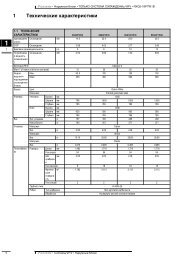
<strong>TopVent</strong> ® DHVTechnical Data3 Technical dataUnit typeFan speedRPM (nominal) min -1Nominal air flow ratem³ / hFloor area reached 1) max. m²Power consumption (at 400 V / 50 Hz) kWCurrent consumption (at 400 V / 50 Hz) ADHV-6 / AI II690 9004500 6100361 5290.48 0.690.78 1.25DHV-6 / BI II690 9004300 5900361 5290.48 0.690.78 1.25DHV-6 / CI II690 9003800 5300324 4410.48 0.690.78 1.25Unit typeFan speedRPM (nominal) min -1Nominal air flow ratem³ / hFloor area reached 1) max. m²Power consumption (at 400 V / 50 Hz) kWCurrent consumption (at 400 V / 50 Hz) ADHV-9 / AI II680 9006600 8700625 9000.70 0.981.15 1.75DHV-9 / BI II680 9006600 8700625 9000.70 0.981.15 1.75DHV-9 / CI II680 9006000 7900529 7840.70 0.981.15 1.75Unit typeFan speedRPM (nominal) min -1Nominal air flow ratem³ / hFloor area reached 1) max. m²Power consumption (at 400 V / 50 Hz) kWCurrent consumption (at 400 V / 50 Hz) ADHV-10 / AI II660 8607500 9700729 10890.99 1.531.77 3.35DHV-10 / BI II660 8607500 9700729 10890.99 1.531.77 3.35DHV-10 / CI II660 8606900 8900625 9610.99 1.531.77 3.351)Mounting height H max = 11 m up to 30 K temperature difference supply air - room airTable B3–1: Technical data of <strong>TopVent</strong> ® DHVUnit type referenceUnit type<strong>TopVent</strong> ® DHVUnit size6, 9 or 10Heat exchangerCoil type A, B or CDHV – 6 / AUnit typeFan speedSound pressure level (5 m distance) 1) dB(A)Total sound power leveldB(A)Octave sound power level 63 Hz dB125 Hz dB250 Hz dB500 Hz dB1000 Hz dB2000 Hz dB4000 Hz dB8000 Hz dBDHV-6I II47 5369 7575 7973 7968 7664 7064 7161 6854 6247 55DHV-9I II52 5874 8079 8374 8374 7968 7470 7568 7562 6855 62DHV-10I II61 6883 9094 9987 9487 9480 8777 8471 7864 7255 631)with hemispherical radiation in a room with little reflectionTable B3–2: Unit type referenceTable B3–3: Sound level of <strong>TopVent</strong> ® DHV10
<strong>TopVent</strong> ® DHVTechnical DataBDHV-6Air inlet temperatureLPHW Unit type°C90 / 70 DHV-6 / A IIIDHV-6 / B IIIDHV-6 / C III80 / 60 DHV-6 / A IIIDHV-6 / B IIIDHV-6 / C III10 °CQ t S H max m W p WkW °C m l / h kPa39 35 8.9 1700 846 32 12.4 2100 1049 43 7.6 2200 1160 39 10.6 2700 16— — — — —89 58 7.7 4000 1033 31 9.6 1400 639 28 13.6 1700 841 38 8.1 1800 951 35 11.3 2200 1259 55 6.0 2600 576 51 8.2 3300 715 °CQ t S H max m W p WkW °C m l / h kPa36 38 9.3 1600 743 36 12.8 1900 945 46 7.8 2000 1055 42 11.0 2400 14— — — — —82 60 8.0 3600 830 34 10.1 1300 536 32 14.1 1600 738 41 8.4 1700 746 38 11.9 2000 1054 56 6.2 2400 469 53 8.6 3000 620 °CQ t S H max m W p WkW °C m l / h kPa33 42 9.5 1400 639 39 13.5 1700 841 49 8.1 1800 851 46 11.3 2200 12— — — — —— — — — —27 38 10.4 1200 432 36 14.6 1400 634 43 9.0 1500 641 41 12.5 1800 948 58 6.5 2100 362 55 9.0 2700 570 / 50 DHV-6 / A IIIDHV-6 / B IIIDHV-6 / C III27 27 10.6 1200 432 25 14.8 1400 634 33 8.8 1500 641 30 12.6 1800 949 47 6.5 2100 462 44 9.0 2700 524 30 11.3 1000 328 29 15.4 1200 530 35 9.5 1300 536 33 13.3 1600 743 48 6.8 1900 355 45 9.5 2400 420 34 11.7 900 325 32 16.7 1100 426 38 10.0 1100 432 36 14.1 1400 637 49 7.3 1600 248 47 10.1 2100 360 / 40 DHV-6 / A IIIDHV-6 / B IIIDHV-6 / C III20 22 12.4 800 324 21 17.1 1000 426 27 10.1 1100 431 25 14.3 1400 636 37 7.4 1600 247 36 10.1 2100 416 25 13.6 700 220 25 18.0 900 321 30 10.8 900 327 28 15.5 1200 430 38 8.0 1300 239 37 11.0 1700 312 28 15.2 500 115 28 20.2 700 217 32 12.1 700 221 31 16.8 900 323 38 9.0 1000 131 37 12.5 1300 282 / 71 DHV-6 / A IIIDHV-6 / B IIIDHV-6 / C III37 34 9.0 3000 2045 31 12.7 3600 2847 42 7.7 3800 3158 38 10.8 4700 4467 60 5.7 5300 1785 56 7.8 6900 2634 37 9.5 2800 1841 35 13.0 3300 2443 45 7.9 3500 2753 41 11.2 4300 38— — — — —78 58 8.1 6300 2231 41 9.7 2500 1538 38 13.8 3000 2140 47 8.4 3200 2349 45 11.5 3900 32— — — — —71 60 8.5 5700 19— Operating conditions not allowed because the maximum supply air temperature of 60 °C is exceeded.Legend: Q = Heat outputt S= Supply air temperatureH max = Maximum mounting heightm W= Water flow ratep W = Water pressure dropTable B3–4: Heat outputs of <strong>TopVent</strong> ® DHV-611
<strong>TopVent</strong> ® DHVTechnical DataDHV-9Air inlet temperatureLPHW Unit type°C90 / 70 DHV-9 / A IIIDHV-9 / B IIIDHV-9 / C III80 / 60 DHV-9 / A IIIDHV-9 / B IIIDHV-9 / C III10 °CQ t S H max m W p WkW °C m l / h kPa62 37 8.9 2800 374 34 12.0 3300 482 46 7.8 3600 499 43 10.4 4400 6— — — — —134 59 8.0 5900 852 33 9.5 2300 262 30 13.0 2700 369 40 8.5 3000 382 37 11.4 3600 493 55 6.5 4100 5114 51 8.6 5000 615 °CQ t S H max m W p WkW °C m l / h kPa57 40 9.2 2500 268 38 12.3 3000 376 49 8.1 3300 491 45 10.9 4000 5— — — — —124 60 8.4 5500 747 36 10.0 2100 256 34 13.5 2500 262 43 8.8 2700 375 40 11.9 3300 484 56 6.9 3700 4103 53 9.0 4500 520 °CQ t S H max m W p WkW °C m l / h kPa52 44 9.5 2300 262 41 13.0 2800 369 51 8.5 3100 383 48 11.4 3700 4— — — — —— — — — —42 39 10.5 1900 150 37 14.3 2200 256 45 9.3 2500 267 43 12.4 2900 376 58 7.1 3300 393 55 9.4 4100 470 / 50 DHV-9 / A IIIDHV-9 / B IIIDHV-9 / C III41 28 10.6 1800 150 26 14.5 2200 256 34 9.3 2400 266 32 12.5 2900 376 47 7.1 3300 393 44 9.4 4100 535 31 11.3 1500 143 30 15.0 1900 249 37 9.8 2100 259 35 13.1 2600 368 48 7.5 3000 383 46 9.9 3600 429 33 12.5 1300 136 32 16.8 1600 142 39 10.5 1800 151 37 14.3 2200 259 49 8.0 2600 272 47 10.6 3200 360 / 40 DHV-9 / A IIIDHV-9 / B IIIDHV-9 / C III26 22 12.8 1100 132 21 17.2 1400 138 26 11.2 1600 148 26 14.5 2100 256 37 8.1 2400 271 36 10.6 3100 321 24 14.7 900 125 23 20.2 1100 129 28 12.4 1300 137 27 16.7 1600 146 37 9.0 2000 158 37 11.5 2500 216 27 16.7 700 119 26 23.4 800 121 30 14.1 900 126 29 19.3 1100 136 38 9.9 1600 145 37 13.1 2000 182 / 71 DHV-9 / A IIIDHV-9 / B IIIDHV-9 / C III61 36 9.0 4900 772 34 12.0 5800 1080 45 7.9 6400 1296 42 10.5 7700 16104 60 6.3 8400 15128 57 8.1 10300 2256 40 9.2 4500 666 37 12.6 5300 973 48 8.2 5900 1088 45 10.9 7100 14— — — — —118 59 8.4 9400 1951 43 9.7 4100 561 41 13.0 4900 767 50 8.6 5400 980 47 11.5 6400 12— — — — —107 60 8.9 8600 16— Operating conditions not allowed because the maximum supply air temperature of 60 °C is exceeded.Legend: Q = Heat outputt S= Supply air temperatureH max = Maximum mounting heightm W= Water flow ratep W = Water pressure dropTable B3–5: Heat outputs of <strong>TopVent</strong> ® DHV-912
<strong>TopVent</strong> ® DHVTechnical DataBDHV-10Air inlet temperatureLPHW Unit type°C90 / 70 DHV-10 / A IIIDHV-10 / B IIIDHV-10 / C III80 / 60 DHV-10 / A IIIDHV-10 / B IIIDHV-10 / C III10 °CQ t S H max m W p WkW °C m l / h kPa68 36 10.1 3000 379 33 13.5 3500 490 44 9.0 4000 5106 41 11.8 4700 7122 60 7.0 5400 7146 57 9.0 6500 1057 32 10.9 2500 266 30 14.4 2900 375 39 9.6 3300 488 36 12.8 3900 5103 53 7.5 4500 5124 50 9.7 5400 715 °CQ t S H max m W p WkW °C m l / h kPa62 39 10.6 2700 373 37 13.9 3200 382 47 9.3 3600 497 44 12.2 4300 6— — — — —135 59 9.4 6000 851 35 11.5 2300 260 33 15.3 2600 368 41 10.2 3000 380 39 13.4 3500 494 55 7.8 4100 5112 52 10.1 4900 620 °CQ t S H max m W p WkW °C m l / h kPa57 43 10.9 2500 266 40 14.7 2900 375 50 9.6 3300 489 47 12.8 3900 5— — — — —— — — — —46 38 12.1 2000 254 36 16.3 2400 261 44 10.6 2700 372 42 14.0 3100 484 56 8.2 3700 4101 54 10.6 4400 570 / 50 DHV-10 / A IIIDHV-10 / B IIIDHV-10 / C III45 27 12.3 2000 253 26 16.0 2300 260 33 10.7 2600 371 31 14.1 3100 485 45 8.2 3700 4101 43 10.6 4400 539 30 13.1 1700 147 29 17.2 2000 253 36 11.2 2300 263 34 14.9 2700 375 47 8.6 3300 390 45 11.1 3900 432 33 14.1 1400 139 32 18.6 1700 146 38 12.1 2000 254 37 15.8 2400 266 48 9.2 2900 379 46 12.0 3400 360 / 40 DHV-10 / A IIIDHV-10 / B IIIDHV-10 / C III29 21 15.0 1300 135 20 20.0 1500 142 26 12.6 1800 152 25 16.5 2300 263 36 9.4 2700 278 35 12.0 3400 423 24 16.6 1000 127 23 22.4 1200 132 28 14.0 1400 141 27 18.5 1800 152 37 10.2 2300 264 36 13.1 2800 317 27 18.9 700 120 26 25.9 900 123 29 16.7 1000 128 29 21.4 1200 140 37 11.5 1700 150 37 14.6 2200 282 / 71 DHV-10 / A IIIDHV-10 / B IIIDHV-10 / C III66 35 10.3 5300 877 33 13.5 6200 1187 43 9.1 7000 14103 41 11.8 8300 19116 58 7.2 9300 18140 55 9.2 11200 2661 39 10.6 4900 771 36 14.2 5700 1080 46 9.4 6400 1295 44 12.2 7600 16106 60 7.4 8500 16128 57 9.6 10300 2255 42 11.1 4400 665 40 14.7 5200 873 49 9.8 5800 1086 46 13.0 6900 14— — — — —117 59 10.0 9400 19— Operating conditions not allowed because the maximum supply air temperature of 60 °C is exceeded.Legend: Q = Heat outputt S= Supply air temperatureH max = Maximum mounting heightm W= Water flow ratep W = Water pressure dropTable B3–6: Heat outputs of <strong>TopVent</strong> ® DHV-1013
<strong>TopVent</strong> ® DHVTechnical Data28E4 x M10TNFGHJCReturnFlowRBDAUnit typeAmmBmmCmmTmmEmmFmmGmmHmmJ "NmmRmmDmmWeightkgWater content Typeof heater battery lDHV-690090541540594758322244Rp 1¼ (female)3097750097A B C2.8 2.8 5.7DHV-91100105048040846882367289Rp 1½ (female)301120630148A B C4.3 4.3 8.6DHV-101100105048040846882367289Rp 1½ (female)1461242630182A B C4.3 4.3 8.6Table B3–7: Dimensions and weights of <strong>TopVent</strong> ® DHVMaximum operating pressure800 kPaMaximum heating medium temperature 120 °CMaximum supply air temperature 60 °CMaximum ambient temperature 40 °CTable B3–8: Application limits of <strong>TopVent</strong> ® DHV14
<strong>TopVent</strong> ® DHVTechnical DataBZRWXYUnit typeFan speedUnit height RmWall distance W min. mmax. mUnit distance X min. m(centre to centre) max. mMounting height Y 1) min. mCeiling distance Z min. mDHV-6 / AI II0.977 0.9775 69.5 11.510 1219 234 40.3 0.3DHV-6 / BI II0.977 0.9775 5.59.5 11.510 1119 234 40.3 0.3DHV-6 / CI II0.977 0.9775 5.59 10.510 1118 214 40.3 0.3Unit typeFan speedUnit height RmWall distance W min. mmax. mUnit distance X min. m(centre to centre) max. mMounting height Y 1) min. mCeiling distance Z min. mDHV-9 / AI II1.120 1.1206 712.5 1512 1425 305 50.4 0.4DHV-9 / BI II1.120 1.1206 712.5 1512 1425 305 50.4 0.4DHV-9 / CI II1.120 1.1206 6.511.5 1412 1323 285 50.4 0.4Unit typeFan speedUnit height RmWall distance W min. mmax. mUnit distance X min. m(centre to centre) max. mMounting height Y 1) min. mCeiling distance Z min. mDHV-10 / AI II1.242 1.2426.5 7.513.5 16.513 1527 335 50.4 0.4DHV-10 / BI II1.242 1.2426.5 7.513.5 16.513 1527 335 50.4 0.4DHV-10 / CI II1.242 1.2426 712.5 15.512 1425 315 50.4 0.41)With the option 'Air outlet box' the minimum mounting height is 1 m lower in each case (see part K 'Options').Table B3–9: Minimum and maximum distances15
<strong>TopVent</strong> ® DHVTechnical DataPressure drop increase in Pa1201101009080706050403020DHV-6 / ADHV-6 / BDHV-6 / CDHV-6 / ADHV-6 / BDHV-6 / CExample:An additional pressure drop of46 Pa at 6100 m³/h results in anew air flow rate of 5300 m³/h.speed IIspeed IIspeed IIspeed Ispeed Ispeed I1003000 3500 4000 4500 500053005500 6000 6500 7000 7500 8000Air flow rate in m³ / hDiagram B3–1: Air flow rate for <strong>TopVent</strong> ® DHV-6 with additional pressure dropPressure drop increase in Pa1201101009080706050403020DHV-9 / ADHV-9 / BDHV-9 / CDHV-9 / ADHV-9 / BDHV-9 / Cspeed IIspeed IIspeed IIspeed Ispeed Ispeed I1004000 4500 5000 5500 6000 6500 7000 7500 8000 8500 9000Air flow rate in m³ / hDiagram B3–2: Air flow rate for <strong>TopVent</strong> ® DHV-9 with additional pressure drop16
<strong>TopVent</strong> ® DHVTechnical DataB120Pressure drop increase in Pa11010090807060504030DHV-10 / A speed IIDHV-10 / B speed IIDHV-10 / C speed IIDHV-10 / A speed IDHV-10 / B speed IDHV-10 / C speed I201005000 5500 6000 6500 7000 7500 8000 8500 9000 9500 10000Air flow rate in m³ / hDiagram B3–3: Air flow rate for <strong>TopVent</strong> ® DHV-10 with additional pressure drop17
<strong>TopVent</strong> ® DHVOptions4 OptionsA wide range of accessories allows customisation of <strong>TopVent</strong> ® DHV units for each individualproject. For a detailed description of all optional components please refer to part K 'Options' ofthis handbook.Paint finishSuspension setIsolation switchActuatorfor Air-InjectorFilter boxAcoustic cowlRecirculation silencerAir outlet boxExplosion-proofcomponentsIn the Hoval standard colours red / orange (for free)or in any desired colour (extra charge)For fastening the unit to the ceilingExternal on / off mains switchFor adjustment of the Air-Injectors when using a non-Hovalcontrol system(for Hoval control equipment see section 5 'Control systems')For filtering recirculated airFor lowering the noise level in the room(reduced noise radiation from the Air-Injector)For lowering the noise level in the room(reduced noise reflection from the ceiling)For use on <strong>TopVent</strong> ® DHV units in low spaces(replaces the Air-Injector)For use of <strong>TopVent</strong> ® DHV units in explosive areas (zone 1 and zone 2),only for DHV-6 and DHV-9Table B4–1:Options available with<strong>TopVent</strong> ® DHV18
<strong>TopVent</strong> ® DHVControl SystemsB5 Control systemsFor <strong>TopVent</strong> ® DHV units, specially developed and optimised components for room temperatureand air distribution control are available from Hoval. For a detailed description of thesecomponents please refer to part L 'Control systems' of this handbook.5.1 Room temperature controlTempTronicEasyTronicThis is a programmable, electronic temperature controller allowingfully automatic operation. Its control algorithm with fuzzy logic ensuressmallest room temperature deviations from setpoints and minimisesenergy consumption.This is a basic temperature controller without clock. The desired roomtemperature is manually adjusted and the fan speed selected with aswitch.Table B5–1:Room temperature controlsystems for <strong>TopVent</strong> ® DHV5.2 Air distribution controlAutomatic controlwith the VarioTronicThe VarioTronic is an electronic controller for the Air-Injector.It adjusts air distribution for changing operating conditions (fan speed,temperature difference between supply air and room air) and worksindependently of room temperature control.Manual control bymeans of potentiometerand actuatorWhere operating conditions change rarely or comfort requirements arenot so high, air distribution may be controlled manually by means of apotentiometer.Fixed adjustmentWhere the basic conditions remain unchanged (constant supply airtemperature, constant air flow rate), air distribution can be manuallyfixed at commissioning.Table B5–2:Air distribution controlsystems for <strong>TopVent</strong> ® DHVFor indoor climate systems where <strong>TopVent</strong> ® DHV units are combined with RoofVent ® freshair units all control is by Hoval DigiNet.19
<strong>TopVent</strong> ® DHVSystem Design6 System designExampleCollect basic data• Space dimensions (floor plan)• Mounting height (= distance from floor to underside of the<strong>TopVent</strong> ® unit)• Required heat output• Desired room temperature• Heating medium temperature (flow / return)• Comfort requirements (acoustic)Space dimensions .......................50 m x 70 mMounting height ..........................10 mRequired heat output ..................350 kWDesired room temperature ..........20 °CHeating medium temperature .....80 / 60 °CComfort requirements .................StandardComfort requirements (acoustic)According to acoustic requirements define the fan speed:Low sound level low fan speed (speed I)Normal sound level high fan speed (speed II)In this project the acoustic requirements are'standard', hence use the high fan speed(speed II) for design calculations.Mounting height• With the minimum mounting height (table B3-9) check which units canbe used.• Check maximum mounting height according to heating mediumtemperature and inlet air temperature (= room temperature) (tablesB3-4, B3-5 and B3-6).• Eliminate units that cannot be used.According to table B3-9 the minimummounting heights are:DHV-6 ..................... 4 mDHV-9, DHV-10 ...... 5 mConsequently, all sizes can be used in thisproject with a mounting height of 10 m.According to tables B3-4, B3-5 and B3-6 andthe given conditions (heating medium temperature80 / 60 °C, inlet air temperature 20 °C)the following unit types cannot be employeddue to the maximum mounting height:DHV-6 / C ................. H max = 9.0 mDHV-9 / C ................. H max = 9.4 mMinimum and maximum number of unitsFor determining the minimum number of units three criteria must befulfilled:a) Minimum number relating to floor areaTable B3-1 indicates the maximum floor area that can be reached with<strong>TopVent</strong> ® DHV units. With these values and the given floor area theminimum number of units can be determined for each unit size andcoil type.b) Minimum number relating to space dimensions (length x width)Depending on space dimensions, a certain minimum number of unitsare required in the length and in the width. This can be calculatedfrom the maximum distances between units and to the wall (see tableB3-9).Calculate the minimum numbers accordingto a), b) and c) for each unit type and enterthem in a table. Then take the highest value asminimum number of units d).Calculate the maximum possible numberaccording to e) and enter the values in thetable.20
<strong>TopVent</strong> ® DHVSystem DesignBc) Minimum number relating to heat outputThe minimum number for each unit size and coil type can becalculated from the required total heat output (tables B3-4, B3-5and B3-6).d) Effective minimum number of unitsThe highest value of the foregoing calculations a), b) and c) is theeffective minimum number of units that should be installed.e) Maximum number of unitsThe minimum number determined under d) normally correspondsto the solution selected in practice as it incurs the lowest costs.Yet if comfort requirements are particularly high more units may beprovided. The maximum number of units is theoretically determinedfrom the total floor area divided by the minimum floor area reachedper unit X 2 (X = minimum distance between units, see table B3-9).Type a) b) c) d) e)DHV-6 / A 7 9 11 11 24DHV-6 / B 7 9 9 9 28DHV-6 / C no solutionDHV-9 / A 4 6 7 7 17DHV-9 / B 4 6 6 6 17DHV-9 / C no solutionDHV-10 / A 4 6 7 7 15DHV-10 / B 4 4 5 6 15DHV-10 / C 4 6 4 6 17Definite number of unitsAccording to space dimensions, comfort requirements and costs, selectthe optimum solution from the remaining alternatives.Due to the space dimensions, comfort requirementsand the investment made available thesolution with 6 <strong>TopVent</strong> ® DHV-9 / B is selectedfrom the remaining variants.Automatic control• Group units working under equal operating conditions (room temperature,heat demand, operating times) into control zones. Checkmaximum switching power of the controller.• Check if, in view of operating conditions, automatic control of the airdistributor with the VarioTronic is worthwhile.The low-cost solution is 1 TempTroniccontroller for all 6 units:Switching power = 6 x 0.98 kW < 6.5 kWThe maximum floor area reached depends on the one handon local conditions and on the other hand on the quality of airdistribution. Due to the complexity of air flow mechanisms in largerooms the design quantities can only partly be mathematicallydescribed. The quality of the air distributor affects the suppliedenergy made available in the occupied area as a function ofthe air flow rate, the temperature difference between supply airand room air and the mounting height. Tests on the test rig andthe experience of numerous applications show that with theAir-Injector this conversion of energy is effected with considerablyhigher efficiency than with other air distributors usually employedin recirculation units. This higher quality leads to lower runningcosts as well as to a larger floor area reachedand thus fewer units are needed.To facilitate the design process concerningthe floor area reached we have decided todispense with complicated formulas anddiagrams. However, it is important to keep tothe limiting values and to make sure that theprimary and secondary air flow can spreadunhindered. If the given limits are exceeded inyour application please seek Hoval advice.21
<strong>TopVent</strong> ® DHVTransport and Installation7 Transport and installationTransport and installation to be carried out byexperts only !A lifting appliance is required for transportation andinstallation of the units !Do not tilt or lay the unit on its side !7.1 InstallationFor fastening to the ceiling, the unit is equipped withfour M10 captive nuts with hexagon head screws andwashers as standard. With these and the height adjustablesuspension set (option) the unit is easily fixed to the ceiling.The captive nuts are only designed for the unit's ownweight. Do not put on any additional loads !The captive nuts cannot sustain a bending moment;therefore do not use eyebolts !Installation by means of steel flat, slotted steel flat, angleor steel wire is also possible, but the following has to beconsidered:7.2 Hydraulic installationHydraulic installation to be carried out by expertsonly !• Combine units working under equal operating conditions(room temperature, heat gain, operating time, etc.) intoone control zone.• Low or medium pressure hot water up to 120 °C can beused as a heating medium. To save energy, the distributorcan be pre-calibrated; it should, however, be ensured thatthe heat requirement of each heater battery can alwaysbe met.• Connect the individual heating coils as shown in figureB7–2. Depending on local conditions, it should alsobe considered whether compensations for flow andreturn pipework are needed to balance the longitudinalexpansion and / or flexible connections for the units.The heat exchanger cannot take up any extraload, e.g. through the flow or return pipe.• The individual units within a control zone must behydraulically balanced to ensure even temperatures.• Non-vertical suspensions are permissible up toa maximum angle of 45°.• The unit must be installed with its top facehorizontal (level)!max.45°max. 45°Air ventBalancing valveDrain cocksIsolating valvesFlowReturnFig. B7–1: Suspension of<strong>TopVent</strong> ® DHVFig. B7–2: Heating coilconnection22
<strong>TopVent</strong> ® DHVTransport and InstallationB7.3 Electrical installationThe electrical connections to the unit must be carriedout by an electrical expert. Relevant regulations mustbe observed.The unit is delivered ready for use.• Check that the local operating voltage, frequency andfusing are in accordance with the information on thenameplate. If any discrepancies occur the unit must notbe connected!• Check cable diameters when using long wiring runs.• Electrical installation to be carried out according to thewiring diagram for the control equipment.• Connection of the <strong>TopVent</strong> ® units to be carried outaccording to the wiring diagram.Connect thermal relays built into the motor;otherwise the motor is not protected againstoverheating.• Do not forget to install a main switch for the wholesystem (control, units).• Several <strong>TopVent</strong> ® units can be connected in parallel.Thermal relays and isolation switches must bewired in series !Isolation switch(optional)Low fan speed (Y connection)Fan(wiring by the installer)Filter pressureswitch(optional)ThermalrelayHigh fan speed ( connection)(wiring by the installer)Fig. B7–3: Wiring diagram for <strong>TopVent</strong> ® DHV23
<strong>TopVent</strong> ® DHVSpecification texts8 Specification texts<strong>TopVent</strong> ® DHVRecirculation unit for heating high spacesCasing made of corrosion-resistant Aluzinc sheet steel.For fastening to the ceiling, the unit is equipped with fourM10 captive nuts with hexagon head screws and washersas standard.Heat exchanger of copper tubes with aluminium fins.Headers are made of steel.Fan unit consisting of a 2-speed three-phase motor of theexternal-rotor type with rigid sickle-shaped aluminium bladeimpeller, maintenance-free and quiet at high efficiency.Motor protection with built-in thermal relays. Protectionrating IP54.Terminal box built into the casing sidewall for connection ofmains supply and accessories.Vortex air distributor with concentric outlet nozzle, twelveadjustable guide vanes and integrated sound attenuationcowl.Actuator for Air-Injector VT-AComplete with cable, for adjustment of the Air-Injector whenusing a non-Hoval control system.Filter box FKWith two bag filters class G4 (to DIN EN 779).Filter pressure switch FUDHVFor supervision of filter cleaning intervals.Acoustic cowl AHDConsisting of a sound attenuation cowl with bigger volumeand a faceplate with sound-insulation lining, insertionattenuation 4 dB(A).Recirculation silencer USDFitted on top of the unit, made of Aluzinc sheet steel withsound-insulation inlay, insertion attenuation 3 dB(A).Air outlet box AKConsisting of Aluzinc sheet steel with four adjustablehorizontal grilles (replaces the Air-Injector).Technical dataFan speed I IINominal air flow rate ______ ______ m³ / hFloor area reached ______ ______ m²Mounting height ______ ______ mNominal heating capacity ______ ______ kWwith LPHW ______ ______ °Cand air inlet temperature ______ ______ °CPower consumption ______ ______ kWCurrent consumption ______ ______ AVoltage400 V / 50 HzDHV-6 / A DHV-6 / B DHV-6 / CDHV-9 / A DHV-9 / B DHV-9 / CDHV-10 / A DHV-10 / B DHV-10 / CStandard paint finish SLIn the Hoval colours red (RAL 3000) and orange (RAL 2008).Special paint finish ALIn RAL colour No. ______Suspension set AHSFor fastening the units to the ceiling, consisting of 4 pairs ofAluzinc steel U sections, height adjustable up to 1300 mm.Paint finish as for the unit.Isolation switch RSIn the terminal box of the <strong>TopVent</strong> ® unit.24
<strong>TopVent</strong> ® DHVSpecification textsB<strong>TopVent</strong> ® DHV EExRecirculation unit with explosion-proof componentsfor heating high spacesCasing made of corrosion-resistant Aluzinc sheet steel.For fastening to the ceiling, the unit is equipped with fourM10 captive nuts with hexagon head screws and washersas standard.Incl. measures avoiding electrostatic charge.Heat exchanger of copper tubes with aluminium fins.Headers are made of steel.Fan unit consisting of a 1-speed radial fan in explosionproofdesign. Motor protection with built-in PTC resistor.Protection rating IP44.Terminal box built into the casing sidewall for connection ofmains supply and accessories.Vortex air distributor with concentric outlet nozzle, twelveadjustable guide vanes and integrated sound attenuationcowl.Technical dataNominal air flow rate______ m³ / hFloor area reached ______ m²Mounting height______ mNominal heating capacity ______ kWwith LPHW ______ °Cand air inlet temperature ______ °CPower consumption______ kWCurrent consumption______ AVoltage400 V / 50 HzDHV-6 / A EEx DHV-6 / B EEx DHV-6 / C EExDHV-9 / A EEx DHV-9 / B EEx DHV-9 / C EExStandard paint finish SLIn the Hoval colours red (RAL 3000) and orange (RAL 2008).Special paint finish ALIn RAL colour No. ______Suspension set AHSFor fastening the units to the ceiling, consisting of 4 pairs ofAluzinc steel U sections, height adjustable up to 1300 mm.Paint finish as for the unit.Room temperature control with the TempTronicElectronic controller with 2-speed 2-point control, fuzzylogic, clock with automatic summer / winter changeover andholiday programme.• TempTronic SH, controller for heating operation, built aswall unit in a plastic casing with transparent lid, room airsensor included• TempTronic SH-S, controller for heating operation,built for installation in a control panel (without casing,transformer, contactors and fuses), room air sensorincluded• Three additional room air sensors for averaging TS1M• Cylinder lock ZS for TempTronic wall unitRoom temperature control with the EasyTronicBasic controller with 2-point control and manual fan speedswitching.• EasyTronic ET, controller for heating operation, built aswall unit in a plastic casing with transparent lid, roomthermostat includedAutomatic air distribution control with the VarioTronicElectronic controller with well-proven control algorithm forchanging operating conditions.• VarioTronic VT-W, control module built as wall unit, in aplastic casing with transparent lid• VarioTronic VT-S, control module for installation in acontrol panel (without casing, transformer, contactor andfuses)• Cylinder lock ZS for VarioTronic wall unit• Actuator VT-AK with cable, plug, supply air sensor androom air sensor• Actuator VT-AS with cable and plug• Separate room air sensor TS1Manual air distribution control with the potentiometerManual control by means of a potentiometer and actuatorwith a range of 0° to 50° for adjustment of the air dischargeangle between vertical and horizontal.• Potentiometer wall unit PMS-W• Potentiometer for installation in a control panel PMS-S• Actuator VT-AS with cable and plug• Transformer TA for maximum 7 actuatorsFilter box FK EExIn explosion-proof design, with two bag filters class G4(to DIN EN 779).Filter pressure switch FUDHVFor supervision of filter cleaning intervals (intrinsically safecircuit by the installer).25
<strong>TopVent</strong> ® DKVCRecirculation unit for heating and cooling high spaces1 Intended use __________________________ 282 Function and construction ______________ 293 Technical data _________________________ 304 Options ______________________________ 375 Control systems _______________________ 386 System design ________________________ 397 Transport and installation _______________ 418 Specification texts _____________________ 43
<strong>TopVent</strong> ® DKVIntended Use1 Intended use<strong>TopVent</strong> ® DKV are recirculation unit heaters andcoolers for use in high spaces.Correct usage also entails adherence to the manufacturer'sconditions for installation, initial start-up, operationand maintenance (operating instructions) as well asconsideration of possible malfunctions and of hazards.1.1 User group<strong>TopVent</strong> ® units are only to be installed, operated andserviced by authorised and trained specialists who arefamiliar with and have been instructed on the hazards.The operating instructions are for English-speaking worksengineers and technicians as well as specialists in building,heating and ventilation technology.1.2 Modes of operation<strong>TopVent</strong> ® DKV units have the following operating modes:• Recirculation heating / cooling at low fan speed• Recirculation heating / cooling at high fan speed• Standby• OffThe application limits given in the 'Technical Data' sectionmust be observed.Any utilisation beyond this is considered inappropriate.The manufacturer is not liable for any damages resultingtherefrom.The units are not suitable for use in explosive atmospheres,in high humidity areas or in rooms with a highdust load.1.3 HazardsDespite all of the preventive measures that have been taken,there are certain hazards, which may not be obvious, e.g.:• Danger when working on the electrical system• Items (e.g. tools) can drop down when work is beingdone on the <strong>TopVent</strong> ® unit• Malfunctions due to defective parts• Danger from hot water when working on the heatingsystem28
<strong>TopVent</strong> ® DKVFunction and ConstructionC2 Function and constructionThe <strong>TopVent</strong> ® DKV is used for recirculation heating andcooling; it has been specially developed for application inhigh spaces. The unit is installed under the ceiling. It takesin room air, heats or cools it and injects it back into the roomvia the Air-Injector.Thanks to its powerful and efficient air distribution the<strong>TopVent</strong> ® DKV covers a large area. Therefore, in comparisonwith other systems, fewer units are needed to achieve therequired environment.Two unit sizes, two-speed fans, different coil types and awide variety of accessories provide a tailored solution foreach application.2.1 Unit constructionThe <strong>TopVent</strong> ® DKV consists of the heating / cooling section(with fan, heat exchanger and built-in condensate separator)and the automatically adjustable vortex air distributorAir-Injector. To avoid condensation on the outer surfacethe heating / cooling section is insulated. The componentsare bolted together and can be dismantled, even afterinstallation.Heating / coolingsectionAir-InjectorFig. C2–1: <strong>TopVent</strong> ® DKVunit components2.2 Air distribution with the Air-InjectorThe patented air distributor – called the Air-Injector – isthe core element. Its controllable vane arrangement allowscontinuous adjustment of the air discharge angle. Thesetting depends on the air flow rate ( fan speed), themounting height and the temperature difference betweensupply air and room air. Thus the air is injected into theroom either vertically downwards, conically or horizontally,ensuring that• a large floor area is reached with each <strong>TopVent</strong> ® DKV unit• no draughts occur in the occupied area• temperature stratification in the room is reduced and thusenergy is saved.Casing:consisting of corrosion-resistant Aluzincsheet steel; the heating / cooling section isinsulatedFan:axial fan with low energy consumption,quiet and maintenance-freeHeat exchanger:LPHW / chilled water coil consisting ofcopper tubes with aluminium finsCondensate separator:with condensate drain connectionTerminal boxSound attenuation cowlAir-Injector:patented, automatically adjustable vortex airdistributor for draught-free air distributionover a large areaFig. C2–2: Construction of <strong>TopVent</strong> ® DKV29
<strong>TopVent</strong> ® DKVTechnical Data3 Technical dataUnit typeFan speedRPM (nominal) min -1Nominal air flow ratem³ / hFloor area reached 1) max. m²Power consumption (at 400 V / 50 Hz) kWCurrent consumption (at 400 V / 50 Hz) ADKV-6 / CI II680 9003900 4900324 4000.70 0.981.15 1.75DKV-9 / CI II660 8606600 8700625 9001.00 1.651.80 3.50DKV-9 / DI II660 8606200 8100576 7841.00 1.651.80 3.501)Mounting height H max = 11 m up to 30 K temperature difference supply air - room airTable C3–1: Technical data of <strong>TopVent</strong> ® DKVUnit type referenceUnit type<strong>TopVent</strong> ® DKVUnit size6 or 9Heat exchangerCoil type C or DDKV – 6 / CUnit typeFan speedSound pressure level (5 m distance) 1)Total sound power levelOctave sound power leveldB(A)dB(A)63 Hz dB125 Hz dB250 Hz dB500 Hz dB1000 Hz dB2000 Hz dB4000 Hz dB8000 Hz dBDKV-6I II51 5773 7978 8273 8273 7867 7369 7467 7461 6754 61DKV-9I II60 6782 8993 9886 9386 9379 8676 8370 7763 7154 621)with hemispherical radiation in a room with little reflectionTable C3–2: Unit type referenceTable C3–3: Sound level of <strong>TopVent</strong> ® DHV30
<strong>TopVent</strong> ® DKVTechnical DataCAir inlet temperatureLPHW Unit type°C10 °CQ t S H max m W p WkW °C m l / h kPa15 °CQ t S H max m W p WkW °C m l / h kPa20 °CQ t S H max m W p WkW °C m l / h kPa90 / 70 DKV-6 / C IIIDKV-9 / C IIIDKV-9 / D III— — — — —84 59 7.1 3700 54— — — — —144 58 8.8 6400 9— — — — —— — — — —— — — — —— — — — —— — — — —133 60 9.1 5900 8— — — — —— — — — —— — — — —— — — — —— — — — —— — — — —— — — — —— — — — —80 / 60 DKV-6 / C IIIDKV-9 / C IIIDKV-9 / D III61 55 6.1 2700 572 52 7.6 3100 7100 53 7.2 4400 5122 50 9.5 5400 7— — — — —— — — — —55 56 6.4 2400 465 54 7.9 2900 691 55 7.5 4000 4111 52 9.9 4900 6— — — — —— — — — —49 58 6.6 2200 458 55 8.4 2600 581 57 7.8 3600 499 54 10.4 4400 5— — — — —— — — — —70 / 50 DKV-6 / C IIIDKV-9 / C IIIDKV-9 / D III50 47 6.6 2200 459 44 8.4 2600 582 46 7.8 3600 4100 43 10.4 4400 5105 59 6.5 4600 6130 56 8.4 5700 944 48 7.0 1900 352 46 8.8 2300 473 47 8.3 3200 389 45 10.9 3900 493 59 6.8 4100 5116 57 8.8 5100 838 49 7.5 1700 246 48 9.2 2000 363 49 8.7 2800 277 46 11.7 3400 382 59 7.3 3600 4102 58 9.3 4500 660 / 40 DKV-6 / C IIIDKV-9 / C IIIDKV-9 / D III37 37 7.6 1600 245 36 9.4 1900 361 37 8.9 2600 277 35 11.8 3300 383 48 7.2 3600 4103 47 9.2 4500 630 38 8.2 1300 237 37 10.2 1600 250 37 9.8 2200 263 36 12.9 2700 270 48 7.7 3000 389 47 9.9 3900 524 38 9.2 1000 129 37 11.6 1300 139 37 11.1 1700 149 37 14.3 2100 257 47 8.5 2500 273 47 10.8 3200 382 / 71 DKV-6 / C IIIDKV-9 / C IIIDKV-9 / D III68 60 5.8 5400 1781 57 7.3 6500 23112 59 6.8 9000 17138 56 8.9 11100 25— — — — —— — — — —— — — — —74 59 7.5 5900 20103 60 7.1 8300 15126 57 9.4 10100 21— — — — —— — — — —— — — — —67 60 7.9 5400 17— — — — —115 59 9.8 9200 18— — — — —— — — — —— Operating conditions not allowed because the maximum supply air temperature of 60 °C is exceeded.Legend: Q = Heat outputt S= Supply air temperatureH max = Maximum mounting heightm W= Water flow ratep W = Water pressure dropTable C3–4: Heat outputs of <strong>TopVent</strong> ® DKV31
<strong>TopVent</strong> ® DKVTechnical DataDKV-6Cooling medium temp.t ai rh Unit type°C %24 30 DKV-6 / C III50 DKV-6 / C III70 DKV-6 / C III26 30 DKV-6 / C III50 DKV-6 / C III70 DKV-6 / C III6 / 12 °CQ tot Q sen t S m C m W p W8 / 14 °CQ tot Q sen t S m C m W p W10 / 16 °CQ tot Q sen t S m C m W p WkW kW °C kg / h l / h kPa kW kW °C kg / h l / h kPa kW kW °C kg / h l / h kPa11 11 16 0.1 1600 313 13 16 0.1 1800 411 11 16 0.1 1600 313 13 16 0.3 1800 421 11 16 14.7 3000 926 13 16 17.9 3700 1313 13 16 0.1 1900 415 15 17 0.2 2200 515 12 16 3.2 2200 518 15 17 4.6 2600 729 14 16 22.7 4200 1636 17 16 28.0 5200 239 9 17 0.3 1300 211 11 17 0.1 1500 39 9 17 0.3 1300 211 11 17 0.1 1500 315 9 17 8.2 2100 518 11 18 10.2 2600 611 11 17 0.1 1600 313 13 18 0.1 1900 411 11 17 0.2 1600 313 13 18 0.1 1900 423 11 17 16.5 3300 1029 14 17 21.4 4200 158 8 18 0.1 1100 19 9 19 0.4 1200 28 8 18 0.1 1100 19 9 19 0.2 1200 29 7 19 3.1 1300 210 8 19 2.9 1500 29 9 19 0.3 1300 211 11 19 0.1 1500 39 9 19 0.3 1300 211 11 19 0.1 1500 316 9 19 10.0 2300 520 11 19 12.4 2900 828 30 DKV-6 / C III50 DKV-6 / C III70 DKV-6 / C III15 15 16 0.1 2100 518 18 17 0.1 2600 722 15 16 10.0 3200 1027 18 17 13.2 3900 1438 16 16 31.4 5400 2445 19 16 37.9 6500 3313 13 18 0.2 1900 416 16 18 0.1 2200 516 13 18 3.7 2300 519 15 18 5.8 2800 732 14 17 26.4 4600 1839 17 18 32.1 5600 2611 11 19 0.1 1600 313 13 20 0.1 1900 411 11 19 0.1 1600 313 13 20 0.1 1900 426 12 19 19.6 3700 1232 14 19 25.3 4600 18Legend: t ai = Air inlet temperaturerh = Air inlet humidityQ tot= Total cooling capacityQ sen = Sensible cooling capacityt Sm Cm W= Supply air temperature= Amount of condensate= Water flow ratep W = Water pressure dropTable C3–5: Cooling capacity of <strong>TopVent</strong> ® DKV-632
<strong>TopVent</strong> ® DKVTechnical DataCDKV-9Cooling medium temp.t ai rh Unit type°C %24 30 DKV-9 / C III50 DKV-9 / C III70 DKV-9 / C III26 30 DKV-9 / C III50 DKV-9 / C III70 DKV-9 / C III6 / 12 °CQ tot Q sen t S m C m W p W8 / 14 °CQ tot Q sen t S m C m W p W10 / 16 °CQ tot Q sen t S m C m W p WkW kW °C kg / h l / h kPa kW kW °C kg / h l / h kPa kW kW °C kg / h l / h kPa17 17 16 0.1 2500 321 21 17 0.1 3000 417 17 16 0.4 2500 321 21 17 0.6 3000 434 18 16 23.3 4900 945 23 16 31.7 6500 1421 21 17 0.2 3000 426 26 17 0.3 3700 524 20 17 4.3 3400 430 25 17 6.1 4400 749 22 16 38.3 7000 1663 29 16 48.9 9000 2514 14 17 0.1 2100 217 17 18 0.1 2500 314 14 17 0.1 2100 217 17 18 0.2 2500 323 14 18 13.1 3300 430 18 18 16.3 4300 718 18 18 0.2 2500 321 21 19 0.5 3100 418 18 18 0.1 2500 321 21 19 0.1 3100 438 19 17 27.8 5500 1051 24 18 37.7 7200 1712 12 19 0.2 1700 114 14 19 0.1 1900 212 12 19 0.4 1700 114 14 19 0.5 1900 213 11 19 3.4 1900 215 13 20 3.3 2200 215 15 19 0.1 2100 217 17 20 0.6 2500 315 15 19 0.1 2100 217 17 20 0.5 2500 325 15 19 14.9 3600 534 19 19 21.8 4900 828 30 DKV-9 / C III50 DKV-9 / C III70 DKV-9 / C III24 24 17 0.3 3500 530 30 17 0.1 4300 736 25 17 16.4 5200 948 31 17 22.8 6800 1563 26 16 52.9 9000 2577 32 17 63.7 11000 3521 21 18 0.1 3000 426 26 19 0.1 3700 525 21 19 5.1 3500 533 26 19 8.8 4700 854 23 17 43.4 7700 1967 29 18 54.4 9600 2718 18 20 0.1 2600 322 22 20 0.6 3100 418 18 20 0.2 2600 322 22 20 0.6 3100 443 20 19 32.9 6100 1256 25 19 44.7 8000 2024 30 DKV-9 / D III50 DKV-9 / D III70 DKV-9 / D III25 25 12 0.2 3600 531 31 12 0.5 4500 826 23 13 4.2 3800 634 30 13 6.2 4900 953 26 11 38.4 7500 2068 34 11 50.5 9800 3221 21 14 0.2 3000 426 26 14 0.1 3700 621 21 14 0.4 3000 426 26 14 0.4 3700 640 21 14 26.7 5800 1253 28 14 35.8 7700 2017 17 16 0.2 2400 321 21 16 0.7 3000 417 17 16 0.6 2400 321 21 16 0.1 3000 425 16 16 12.5 3600 533 20 16 17.5 4700 926 30 DKV-9 / D III50 DKV-9 / D III70 DKV-9 / D III29 29 12 0.1 4200 737 37 12 0.4 5300 1140 28 12 16.4 5800 1253 37 12 22.7 7600 2067 31 11 53.5 9700 3184 39 12 66.3 12100 4625 25 14 0.3 3600 532 32 14 0.3 4600 827 23 15 4.9 3800 635 30 15 6.2 5000 1057 27 13 44.2 8200 2372 34 13 56.2 10400 3521 21 16 0.4 3000 427 27 16 0.1 3800 621 21 16 0.2 3000 427 27 16 0.1 3800 644 22 15 31.3 6300 1458 29 15 42.0 8400 2328 30 DKV-9 / D III50 DKV-9 / D III70 DKV-9 / D III33 33 12 0.1 4800 943 43 12 0.4 6100 1454 34 11 29.6 7800 2170 43 12 39.6 10100 3381 35 11 67.6 11600 42101 43 12 84.6 14400 6229 29 14 0.2 4200 738 38 14 0.6 5400 1142 29 14 18.9 6100 1456 38 14 26.6 8000 2272 31 13 59.5 10300 3489 39 14 73.7 12800 5025 25 16 0.4 3600 532 32 16 0.2 4600 827 23 17 4.2 3900 637 30 17 7.9 5200 1062 27 15 49.3 8800 2677 34 15 61.3 11000 38Legend: t ai = Air inlet temperaturerh = Air inlet humidityQ tot= Total cooling capacityQ sen = Sensible cooling capacityt Sm Cm W= Supply air temperature= Amount of condensate= Water flow ratep W = Water pressure dropTable C3–6: Cooling capacity of <strong>TopVent</strong> ® DKV-933
<strong>TopVent</strong> ® DKVTechnical Data27E4x M10NFTHGJBInspectionportCKReturnFlowLMCondensate drainRDAUnit typeAmmBmmCmmTmmEmmFmmGmmHmmJ "KmmLmmM "NmmRmmDmmWeightkgWater content of coil lDKV-6 / C900138089040594758425347Rp 1¼ (female)750120Rp ¾ (female)3014565001605.7DKV-9 / C1100150093040846882488410Rp 1½ (female)850120Rp ¾ (female)3015846302108.6DKV-9 / D1100150093040846882497402Rp 2 (female)850120Rp ¾ (female)30158463023018.3Table C3–7: Dimensions and weights of <strong>TopVent</strong> ® DKV34
<strong>TopVent</strong> ® DKVTechnical DataCMaximum operating pressure800 kPaMaximum heating medium temperature 120 °CMaximum supply air temperature 60 °CMaximum ambient temperature 40 °CMaximum amount of condensate DKV-6Maximum amount of condensate DKV-9Minimum air flow rate DKV-6Minimum air flow rate DKV-940 kg90 kg3100 m³ / h5000 m³ / hTable C3–8: Application limits of <strong>TopVent</strong> ® DKVZRWXYUnit typeFan speedUnit height RmWall distance W min. mmax. mUnit distance X min. m(centre to centre) max. mMounting height Y 1) min. mCeiling distance Z min. mDKV-6 / CI II1.456 1.4565 5.59 1010 1118 204 40.3 0.3DKV-9 / CI II1.584 1.5846 712.5 1512 1425 305 50.4 0.4DKV-9 / DI II1.584 1.5846 6.512 1412 1324 285 50.4 0.41)With the option 'Air outlet box' the minimum mounting height is 1 m lower in each case (see part K 'Options').Table C3–9: Minimum and maximum distances35
<strong>TopVent</strong> ® DKVTechnical Data120110100DKV-6 / CDKV-6 / Cspeed IIspeed IPressure drop increase in Pa9080706050403020Example:An additional pressure drop of45 Pa at 4920 m³/h results in anew air flow rate of 4300 m³/h.1003000 3500 400043004500 5000 5500 6000 6500 7000 7500 8000Air flow rate in m³ / hDiagram C3–1: Air flow rate for <strong>TopVent</strong> ® DKV-6 with additional pressure drop120110100DKV-9 / CDKV-9 / DDKV-9 / CDKV-9 / Dspeed IIspeed IIspeed Ispeed IPressure drop increase in Pa90807060504030201004000 4500 5000 5500 6000 6500 7000 7500 8000 8500 9000Air flow rate in m³ / hDiagram C3–2: Air flow rate for <strong>TopVent</strong> ® DKV-9 with additional pressure drop36
<strong>TopVent</strong> ® DKVOptionsC4 OptionsA wide range of accessories allows customisation of <strong>TopVent</strong> ® DKV units for each individualproject. For a detailed description of all optional components please refer to part K 'Options' ofthis handbook.Paint finishSuspension setIsolation switchActuatorfor Air-InjectorFilter boxAcoustic cowlRecirculation silencerAir outlet boxInsulationCondensate pumpIn the Hoval standard colours red / orange (for free)or in any desired colour (extra charge)For fastening the unit to the ceilingExternal on / off mains switchFor adjustment of the Air-Injectors when using a non-Hovalcontrol system(for Hoval control equipment see section 5 'Control systems')For filtering recirculated airFor lowering the noise level in the room(reduced noise radiation from the Air-Injector)For lowering the noise level in the room(reduced noise reflection from the ceiling)For use on <strong>TopVent</strong> ® DKV units in low spaces(replaces the Air-Injector)Prevents condensation forming on the outer surfacesof the Air-InjectorFor condensate drainage through waste water pipes under the ceilingor onto the roofTable C4–1:Options availablewith <strong>TopVent</strong> ® DKV37
<strong>TopVent</strong> ® DKVControl Systems5 Control systemsFor <strong>TopVent</strong> ® DKV units, specially developed and optimised components for room temperatureand air distribution control are available from Hoval. For a detailed description of thesecomponents please refer to part L 'Control systems' of this handbook.5.1 Room temperature controlTempTronicThis is a programmable, electronic temperature controller allowingfully automatic operation. Its control algorithm with fuzzy logic ensuressmallest room temperature deviations from setpoints and minimisesenergy consumption.Table C5–1:Room temperature controlsystems for <strong>TopVent</strong> ® DKV5.2 Air distribution controlAutomatic controlwith the VarioTronicThe VarioTronic is an electronic controller for the Air-Injector.It adjusts air distribution for changing operating conditions (fan speed,temperature difference between supply air and room air) and worksindependently of room temperature control.Manual control bymeans of potentiometerand actuatorWhere operating conditions change rarely or comfort requirements arenot so high, air distribution may be controlled manually by means of apotentiometer.Fixed adjustmentWhere the basic conditions remain unchanged (constant supply airtemperature, constant air flow rate), air distribution can be manuallyfixed at commissioning.Table C5–2:Air distribution controlsystems for <strong>TopVent</strong> ® DKVFor indoor climate systems where <strong>TopVent</strong> ® DKV units are combined with RoofVent ® freshair units all control is by Hoval DigiNet.38
<strong>TopVent</strong> ® DKVSystem DesignC6 System designExampleUsually, the primary function of <strong>TopVent</strong> ® DKV units is cooling; forthis reason the design process is described for this function. Thedesign for heating can be made in a similar way to the example inpart B '<strong>TopVent</strong> ® DHV'.Collect basic data• Space dimensions (floor plan)• Mounting height (= distance from floor to underside of the<strong>TopVent</strong> ® unit)• Required cooling capacity• Desired room conditions• Cooling medium temperature (flow / return)• Comfort requirements (acoustic)Space dimensions .......................55 m x 86 mMounting height ..........................8 mRequired cooling capacity ...........190 kWDesired room conditions .............26 °C / 50 %Cooling medium temperature .....8 / 14 °CComfort requirements .................StandardComfort requirements (acoustic)According to acoustic requirements define the fan speed:Low sound level low fan speed (speed I)Normal sound level high fan speed (speed II)In this project the acoustic requirements are'standard', hence use the high fan speed(speed II) for design calculations.Mounting heightWith the minimum mounting height (table C3-9) check which units canbe used.According to table C3-9 the minimummounting heights are:DKV-6 ..................... 4 mDKV-9 ..................... 5 mConsequently, all sizes can be used in thisproject with a mounting height of 8 m.Minimum and maximum number of unitsFor determining the minimum number of units three criteria must befulfilled:a) Minimum number relating to floor areaTable C3-1 indicates the maximum floor area that can be reached with<strong>TopVent</strong> ® DKV units. With these values and the given floor area theminimum number of units can be determined for each unit size andcoil type.b) Minimum number relating to space dimensions (length x width)Depending on space dimensions, a certain minimum number of unitsare required in the length and in the width. This can be calculatedfrom the maximum distances between units and to the wall (seetable C3-9.Calculate the minimum numbers accordingto a), b) and c) for each unit type and enterthem in a table. Then take the highest value asminimum number of units d).Calculate the maximum possible numberaccording to e) and enter the values in thetable.39
<strong>TopVent</strong> ® DKVSystem Designc) Minimum number relating to cooling capacityThe minimum number for each unit size and coil type can becalculated from the required total cooling capacity (tables C3-5and C3-6).Please note that only the sensible cooling capacity Q sen isavailable for cooling of the space while the total capacity Q totmust be used for sizing the chiller.Type a) b) c) d) e)DKV-6 / C 12 15 15 15 39DKV-9 / C 6 6 9 9 24DKV-9 / D 6 6 7 7 28d) Effective minimum number of unitsThe highest value of the foregoing calculations a), b) and c) is theeffective minimum number of units that should be installed.e) Maximum number of unitsThe minimum number determined under d) normally correspondsto the solution selected in practice as it incurs the lowest costs.Yet if comfort requirements are particularly high more units may beprovided. The maximum number of units is theoretically determinedfrom the total floor area divided by the minimum floor area reachedper unit X 2 (X = minimum distance between units, see table C3-9).Definite number of unitsAccording to space dimensions, comfort requirements and costs, selectthe optimum solution from the remaining alternatives.Due to the space dimensions, comfort requirementsand the investment made availablethe solution with 7 <strong>TopVent</strong> ® DKV-9 / D isselected from the remaining variants.Automatic control• Group units working under equal operating conditions (room temperature,cooling load, operating times) into control zones. Checkmaximum switching power of the controller.• Check if, in view of operating conditions, automatic control of the airdistributor with the VarioTronic is worthwhile.The low-cost solution is 3 TempTroniccontrollers:Switching power = 3 x 1.65 kW < 6.5 kW2 x 1.65 kW < 6.5 kW2 x 1.65 kW < 6.5 kWThe maximum floor area reached depends on the one handon local conditions and on the other hand on the quality of airdistribution. Due to the complexity of air flow mechanisms in largerooms the design quantities can only partly be mathematicallydescribed. The quality of the air distributor affects the suppliedenergy made available in the occupied area as a function ofthe air flow rate, the temperature difference between supply airand room air and the mounting height. Tests on the test rig andthe experience of numerous applications show that with theAir-Injector this conversion of energy is effected with considerablyhigher efficiency than with other air distributors usually employedin recirculation units. This higher quality leads to lower runningcosts as well as to a larger floor area reachedand thus fewer units are needed.To facilitate the design process concerningthe floor area reached we have decided todispense with complicated formulas anddiagrams. However, it is important to keep tothe limiting values and to make sure that theprimary and secondary air flow can spreadunhindered. If the given limits are exceeded inyour application please seek Hoval advice.40
<strong>TopVent</strong> ® DKVTransport and InstallationC7 Transport and installationTransport and installation to be carried out byexperts only !A lifting appliance is required for transportation andinstallation of the units !Do not tilt or lay the unit on its side !7.1 InstallationFor fastening to the ceiling, the unit is equipped withfour M10 captive nuts with hexagon head screws andwashers as standard. With these and the height adjustablesuspension set (option) the unit is easily fixed to the ceiling.The captive nuts are only designed for the unit's ownweight. Do not put on any additional loads !The captive nuts cannot sustain a bending moment;therefore do not use eyebolts !Installation by means of steel flat, slotted steel flat, angleor steel wire is also possible, but the following has to beconsidered:7.2 Hydraulic installationHydraulic installation to be carried out by expertsonly !• Combine units working under equal operating conditions(room temperature, heat gain, operating time, etc.) intoone control zone.• Low or medium pressure hot water up to 120 °C can beused as a heating medium. To save energy, the distributorcan be pre-calibrated; it should, however, be ensured thatthe heat requirement of each heater battery can alwaysbe met.• Connect the individual heating / cooling coils as shownin figure C7–2. Depending on local conditions, it shouldalso be considered whether compensations for flow andreturn pipework are needed to balance the longitudinalexpansion and / or flexible connections for the units.The heat exchanger cannot take up any extraload, e.g. through the flow or return pipe.• Adequately size the slope and cross section of thecondensate drain to prevent a condensate backwash.Install a 200 mm trap.• The individual units within a control zone must behydraulically balanced to ensure even temperatures.• Non-vertical suspensions are permissible up toa maximum angle of 45°.• The unit must be installed with its top facehorizontal (level)!max.45°max. 45°Air ventBalancing valveDrain cocksIsolating valvesFlowReturnCondensate drain(with trap)2-port valveFig. C7–1: Suspension of<strong>TopVent</strong> ® DKVFig. C7–2: Heating / coolingcoil connection41
<strong>TopVent</strong> ® DKVTransport and Installation7.3 Electrical installationThe electrical connections to the unit must be carriedout by an electrical expert. Relevant regulations mustbe observed.The unit is delivered ready for use.• Check that the local operating voltage, frequency andfusing are in accordance with the information on thenameplate. If any discrepancies occur the unit must notbe connected!• Check cable diameters when using long wiring runs.• Electrical installation to be carried out according to thewiring diagram for the control equipment.• Connection of the <strong>TopVent</strong> ® units to be carried outaccording to the wiring diagram.Connect thermal relays built into the motor;otherwise the motor is not protected againstoverheating.• Do not forget to install a main switch for the wholesystem (control, units).• Several <strong>TopVent</strong> ® units can be connected in parallel.Thermal relays and isolation switches must bewired in series !• The condensate separator only works with the fanrunning. Therefore, switch off the cooling pump togetherwith the fan.Isolation switch(optional)Low fan speed (Y connection)Fan(wiring by the installer)Filter pressureswitch(optional)ThermalrelayHigh fan speed ( connection)(wiring by the installer)Fig. C7–3: Wiring diagram for <strong>TopVent</strong> ® DKV42
<strong>TopVent</strong> ® DKVSpecification textsC8 Specification texts<strong>TopVent</strong> ® DKVRecirculation unit for heating and cooling high spacesCasing made of corrosion-resistant Aluzinc sheet steel,heating / cooling section insulated inside. For fastening to theceiling, the unit is equipped with four M10 captive nuts withhexagon head screws and washers as standard.Heat exchanger of copper tubes with aluminium fins.Headers are made of steel. A condensate separator withdrain connection is installed.Fan unit consisting of a 2-speed three-phase motor of theexternal-rotor type with rigid sickle-shaped aluminium bladeimpeller, maintenance-free and quiet at high efficiency.Motor protection with built-in thermal relays. Protectionrating IP54.Terminal box built into the casing sidewall for connection ofmains supply and accessories.Vortex air distributor with concentric outlet nozzle, twelveadjustable guide vanes and integrated sound attenuationcowl.Technical dataFan speed I IINominal air flow rate ______ ______ m³ / hFloor area reached ______ ______ m²Mounting height ______ ______ mNominal cooling capacity ______ ______ kWwith chilled water ______ ______ °Cair inlet temperature ______ ______ °Cand air inlet humidity ______ ______ %Nominal heating capacity ______ ______ kWwith LPHW ______ ______ °Cand air inlet temperature ______ ______ °CPower consumption ______ ______ kWCurrent consumption ______ ______ AVoltage400 V / 50 HzSuspension set AHSFor fastening the units to the ceiling, consisting of 4 pairs ofAluzinc steel U sections, height adjustable up to 1300 mm.Paint finish as for the unit.Isolation switch RSIn the terminal box of the <strong>TopVent</strong> ® unit.Actuator for Air-Injector VT-AComplete with cable, for adjustment of the Air-Injector whenusing a non-Hoval control system.Filter box FKWith two bag filters class G4 (to DIN EN 779).Filter pressure switch FUDHVFor supervision of filter cleaning intervals.Acoustic cowl AHDConsisting of a sound attenuation cowl with bigger volumeand a faceplate with sound-insulation lining, insertionattenuation 4 dB(A).Recirculation silencer USDFitted on top of the unit, made of Aluzinc sheet steel withsound-insulation inlay, insertion attenuation 3 dB(A).Air outlet box AKConsisting of Aluzinc sheet steel with four adjustablehorizontal grilles (replaces the Air-Injector).Insulation IDOf the Air-Injector.Condensate pump KPConsisting of a centrifugal pump, collecting tray and flexiblehose, delivery output max. 80 l / h at 3 m delivery height.DKV-6 / CDKV-9 / CDKV-9 / DStandard paint finish SLIn the Hoval colours red (RAL 3000) and orange (RAL 2008).Special paint finish ALIn RAL colour No. ______43
<strong>TopVent</strong> ® DKVSpecification TextsRoom temperature control with the TempTronicElectronic controller with 2-speed 2-point control, fuzzylogic, clock with automatic summer / winter changeover andholiday programme.• TempTronic SHK, controller for heating and coolingoperation, built as wall unit in a plastic casing withtransparent lid, room air sensor included• TempTronic SHK-S, controller for heating and coolingoperation, built for installation in a control panel (withoutcasing, transformer, contactors and fuses), room airsensor included• Three additional room air sensors for averaging TS1M• Cylinder lock ZS for TempTronic wall unitAutomatic air distribution control with the VarioTronicElectronic controller with well-proven control algorithm forchanging operating conditions.• VarioTronic VT-W, control module built as wall unit, in aplastic casing with transparent lid• VarioTronic VT-S, control module for installation in acontrol panel (without casing, transformer, contactor andfuses)• Cylinder lock ZS for VarioTronic wall unit• Actuator VT-AK with cable, plug, supply air sensor androom air sensor• Actuator VT-AS with cable and plug• Separate room air sensor TS1Manual air distribution control with the potentiometerManual control by means of a potentiometer and actuatorwith a range of 0° to 50° for adjustment of the air dischargeangle between vertical and horizontal.• Potentiometer wall unit PMS-W• Potentiometer for installation in a control panel PMS-S• Actuator VT-AS with cable and plug• Transformer TA for maximum 7 actuators44
<strong>TopVent</strong> ® NHVDRecirculation unit for heating high spaceswith lower comfort requirements (e.g. high rack warehouses)1 Intended use __________________________ 462 Function and construction ______________ 473 Technical data _________________________ 484 Options ______________________________ 565 Control systems _______________________ 576 System design ________________________ 587 Transport and installation _______________ 608 Specification texts _____________________ 62
<strong>TopVent</strong> ® NHVIntended Use1 Intended use<strong>TopVent</strong> ® NHV are recirculation unit heaters for use inhigh spaces.Correct usage also entails adherence to the manufacturer'sconditions for installation, initial start-up, operationand maintenance (operating instructions) as well asconsideration of possible malfunctions and of hazards.1.1 User group<strong>TopVent</strong> ® units are only to be installed, operated andserviced by authorised and trained specialists who arefamiliar with and have been instructed on the hazards.The operating instructions are for English-speaking worksengineers and technicians as well as specialists in building,heating and ventilation technology.1.2 Modes of operation<strong>TopVent</strong> ® NHV units have the following operating modes:• Recirculation heating at low fan speed• Recirculation heating at high fan speed• Standby• OffThe application limits given in the 'Technical Data' sectionmust be observed.Any utilisation beyond this is considered inappropriate.The manufacturer is not liable for any damages resultingtherefrom.In standard design the units are not suitable for usein explosive atmospheres, in high humidity areas orin rooms with a high dust load.1.3 HazardsDespite all of the preventive measures that have been taken,there are certain hazards, which may not be obvious, e.g.:• Danger when working on the electrical system• Items (e.g. tools) can drop down when work is beingdone on the <strong>TopVent</strong> ® unit• Malfunctions due to defective parts• Danger from hot water when working on the heatingsystem46
<strong>TopVent</strong> ® NHVFunction and Construction2 Function and constructionHeating sectionThe <strong>TopVent</strong> ® NHV unit is used for cost-effective recirculationheating in high spaces. The unit is installed underthe ceiling. It takes in room air, heats it by means of theheater battery and injects it back into the room via the outletnozzle. The air discharge angle cannot be adjusted withthe <strong>TopVent</strong> ® NHV. Therefore the unit is specially suited forapplications where comfort requirements are relatively low(e.g. high racking warehouses).Thanks to its high efficiency the <strong>TopVent</strong> ® NHV unit heatercovers a large area. Therefore, in comparison with othersystems, fewer units are needed to achieve the requiredenvironment.Three unit sizes, two-speed fans, different heater batterytypes and a wide variety of accessories provide a tailoredsolution for each application. Furthermore, special batteries(steam, electrical heating) are also available.The <strong>TopVent</strong> ® NHV consists of the heating section (withfan and heater battery) and the outlet nozzle. These twocomponents are bolted together and can be dismantled,even after installation.Outlet nozzleFig. D2–1: <strong>TopVent</strong> ® NHVunit componentsDCasing:consisting of corrosion-resistant Aluzincsheet steelFan:axial fan with low energy consumption,quiet and maintenance freeHeat exchanger:LPHW heater battery consisting of coppertubes with aluminium finsTerminal boxOutlet nozzleFig. D2–2: Construction of <strong>TopVent</strong> ® NHV47
<strong>TopVent</strong> ® NHVTechnical Data3 Technical dataUnit typeFan speedRPM (nominal) min -1Nominal air flow ratem³ / hFloor area reached 1) max. m²Power consumption (at 400 V / 50 Hz) kWCurrent consumption (at 400 V / 50 Hz) ANHV-6 / AI II690 9004600 6300361 5290.48 0.690.78 1.25NHV-6 / BI II690 9004400 6100361 5290.48 0.690.78 1.25NHV-6 / CI II690 9003900 5500324 4410.48 0.690.78 1.25Unit typeFan speedRPM (nominal) min -1Nominal air flow ratem³ / hFloor area reached 1) max. m²Power consumption (at 400 V / 50 Hz) kWCurrent consumption (at 400 V / 50 Hz) ANHV-9 / AI II680 9007100 9400625 9000.70 0.981.15 1.75NHV-9 / BI II680 9007100 9400625 9000.70 0.981.15 1.75NHV-9 / CI II680 9006500 8600529 7840.70 0.981.15 1.75Unit typeFan speedRPM (nominal) min -1Nominal air flow ratem³ / hFloor area reached 1) max. m²Power consumption (at 400 V / 50 Hz) kWCurrent consumption (at 400 V / 50 Hz) ANHV-10 / AI II660 8608100 10500729 10890.99 1.531.77 3.35NHV-10 / BI II660 8608100 10500729 10890.99 1.531.77 3.35NHV-10 / CI II660 8607500 9700625 9610.99 1.531.77 3.351)Mounting height H max = 12 m up to 30 K temperature difference supply air - room airTable D3–1: Technical data of <strong>TopVent</strong> ® NHVUnit type referenceUnit type<strong>TopVent</strong> ® NHVUnit size6, 9 or 10Heat exchangerCoil type A, B or CNHV – 6 / AUnit typeFan speedSound pressure level (5 m distance) 1) dB(A)Total sound power leveldB(A)Octave sound power level 63 Hz dB125 Hz dB250 Hz dB500 Hz dB1000 Hz dB2000 Hz dB4000 Hz dB8000 Hz dBNHV-6I II47 5369 7575 7973 7968 7664 7064 7161 6854 6247 55NHV-9I II52 5874 8079 8374 8374 7968 7470 7568 7562 6855 62NHV-10I II61 6883 9094 9987 9487 9480 8777 8471 7864 7255 631)with hemispherical radiation in a room with little reflectionTable D3–2: Unit type referenceTable D3–3: Sound level of <strong>TopVent</strong> ® NHV48
<strong>TopVent</strong> ® NHVTechnical DataNHV-6Air inlet temperatureLPHW Unit type°C90 / 70 NHV-6 / A IIINHV-6 / B IIINHV-6 / C III80 / 60 NHV-6 / A IIINHV-6 / B IIINHV-6 / C III10 °CQ t S H max m W p WkW °C m l / h kPa39 34 9.2 1700 847 32 12.8 2100 1150 43 7.7 2200 1261 39 10.9 2700 17— — — — —92 58 8.0 4100 1033 31 9.8 1500 640 28 14.0 1800 842 37 8.4 1800 952 34 11.9 2300 1361 55 6.1 2700 578 51 8.5 3400 815 °CQ t S H max m W p WkW °C m l / h kPa36 38 9.5 1600 744 35 13.4 1900 946 45 8.1 2000 1056 42 11.4 2500 15— — — — —84 60 8.2 3700 930 34 10.3 1300 536 32 14.5 1600 738 40 8.8 1700 847 37 12.5 2100 1155 56 6.4 2400 471 52 9.0 3100 720 °CQ t S H max m W p WkW °C m l / h kPa33 41 9.9 1500 640 39 13.9 1800 842 48 8.4 1900 952 45 11.9 2300 12— — — — —— — — — —27 37 10.9 1200 433 35 15.5 1400 634 43 9.2 1500 642 41 12.9 1900 949 58 6.6 2200 463 54 9.4 2800 5D70 / 50 NHV-6 / A IIINHV-6 / B IIINHV-6 / C III27 27 10.8 1200 432 25 15.2 1400 634 32 9.2 1500 642 30 12.9 1800 950 47 6.6 2200 464 43 9.4 2800 624 30 11.5 1000 329 28 16.4 1300 530 35 9.7 1300 537 33 13.7 1600 744 48 7.0 1900 356 45 9.9 2500 521 33 12.4 900 325 32 17.2 1100 426 38 10.2 1200 432 36 14.6 1400 638 49 7.5 1700 249 47 10.4 2200 460 / 40 NHV-6 / A IIINHV-6 / B IIINHV-6 / C III20 22 12.6 900 325 21 17.6 1100 426 27 10.3 1100 432 25 14.8 1400 637 37 7.6 1600 249 36 10.4 2100 416 25 13.8 700 220 24 19.5 900 322 29 11.4 900 327 28 15.9 1200 530 38 8.2 1300 240 37 11.4 1800 313 28 15.5 500 116 27 22.2 700 217 32 12.3 700 222 31 17.4 1000 324 38 9.2 1000 132 37 12.9 1400 282 / 71 NHV-6 / A IIINHV-6 / B IIINHV-6 / C III38 34 9.2 3000 2146 31 13.0 3700 2948 41 7.9 3900 3259 38 11.1 4800 4668 60 5.8 5400 1788 56 8.1 7000 2735 37 9.7 2800 1842 35 13.4 3400 2544 44 8.2 3500 2755 41 11.6 4400 39— — — — —80 58 8.4 6500 2332 41 9.9 2600 1539 38 14.2 3100 2240 47 8.5 3200 2350 44 12.1 4000 34— — — — —73 60 8.7 5900 20— Operating conditions not allowed because the maximum supply air temperature of 60 °C is exceeded.Legend: Q = Heat outputt S= Supply air temperatureH max = Maximum mounting heightm W= Water flow ratep W = Water pressure dropTable D3–4: Heat outputs of <strong>TopVent</strong> ® NHV-649
<strong>TopVent</strong> ® NHVTechnical DataNHV-9Air inlet temperatureLPHW Unit type°C90 / 70 NHV-9 / A IIINHV-9 / B IIINHV-9 / C III80 / 60 NHV-9 / A IIINHV-9 / B IIINHV-9 / C III10 °CQ t S H max m W p WkW °C m l / h kPa65 36 9.6 2900 378 34 12.9 3400 486 45 8.4 3800 5104 42 11.3 4600 6— — — — —143 58 8.7 6300 955 32 10.4 2400 265 30 14.0 2800 372 39 9.2 3200 487 37 12.2 3800 599 54 7.1 4300 5121 50 9.4 5300 715 °CQ t S H max m W p WkW °C m l / h kPa60 40 9.9 2700 371 37 13.5 3200 379 48 8.7 3500 495 45 11.7 4200 6— — — — —131 60 9.0 5800 850 35 10.9 2200 259 33 14.8 2600 265 42 9.5 2900 378 39 13.0 3400 490 55 7.4 3900 4110 52 9.8 4800 620 °CQ t S H max m W p WkW °C m l / h kPa55 43 10.3 2400 265 41 13.9 2900 372 50 9.2 3200 387 48 12.2 3800 5— — — — —— — — — —44 39 11.3 2000 253 37 15.4 2300 259 45 9.9 2600 270 42 13.6 3100 381 57 7.7 3500 399 54 10.3 4300 570 / 50 NHV-9 / A IIINHV-9 / B IIINHV-9 / C III43 28 11.4 1900 252 26 15.5 2300 258 34 10.0 2500 370 31 13.7 3000 381 46 7.7 3500 499 43 10.3 4300 537 30 12.4 1600 146 29 16.7 2000 251 36 10.7 2200 261 34 14.5 2700 372 47 8.2 3100 388 45 10.8 3800 431 33 13.4 1300 138 32 18.1 1700 144 38 11.5 1900 253 37 15.4 2300 263 49 8.6 2700 277 47 11.4 3400 360 / 40 NHV-9 / A IIINHV-9 / B IIINHV-9 / C III28 21 14.3 1200 134 21 18.5 1500 140 26 12.0 1700 151 26 15.5 2200 260 37 8.7 2600 276 35 11.6 3300 322 24 15.8 900 127 23 21.8 1200 131 28 13.3 1300 139 27 17.9 1700 149 37 9.7 2100 263 36 12.7 2700 217 27 17.9 700 119 26 25.2 800 122 29 15.9 1000 128 29 20.7 1200 138 38 10.6 1700 149 37 14.1 2100 282 / 71 NHV-9 / A IIINHV-9 / B IIINHV-9 / C III64 36 9.6 5100 876 33 13.1 6100 1184 44 8.5 6700 13101 41 11.5 8100 18111 59 6.7 8900 17137 56 8.8 11000 2558 39 10.1 4700 770 37 13.5 5600 977 47 8.8 6200 1193 44 11.9 7400 15102 60 7.1 8200 15125 58 9.2 10100 2153 42 10.5 4300 663 40 14.2 5100 870 49 9.3 5600 984 47 12.4 6800 13— — — — —114 59 9.7 9200 18— Operating conditions not allowed because the maximum supply air temperature of 60 °C is exceeded.Legend: Q = Heat outputt S= Supply air temperatureH max = Maximum mounting heightm W= Water flow ratep W = Water pressure dropTable D3–5: Heat outputs of <strong>TopVent</strong> ® NHV-950
<strong>TopVent</strong> ® NHVTechnical DataNHV-10Air inlet temperatureLPHW Unit type°C90 / 70 NHV-10 / A IIINHV-10 / B IIINHV-10 / C III80 / 60 NHV-10 / A IIINHV-10 / B IIINHV-10 / C III10 °CQ t S H max m W p WkW °C m l / h kPa71 35 11.0 3100 383 33 14.6 3700 494 43 9.7 4200 5111 40 12.9 4900 7129 60 7.6 5700 8156 56 9.9 6900 1159 31 11.9 2600 369 29 15.9 3000 379 38 10.5 3500 493 35 14.0 4100 6110 52 8.2 4800 6132 49 10.6 5800 815 °CQ t S H max m W p WkW °C m l / h kPa65 39 11.3 2900 376 36 15.3 3400 487 46 10.1 3800 5102 43 13.4 4500 6— — — — —143 58 10.2 6300 954 34 12.6 2400 263 33 16.5 2800 371 41 10.9 3100 384 38 14.7 3700 599 54 8.5 4400 5120 51 11.1 5300 720 °CQ t S H max m W p WkW °C m l / h kPa60 42 11.9 2600 270 40 15.8 3100 379 49 10.5 3500 493 46 14.0 4100 5— — — — —131 60 10.7 5800 848 38 13.0 2100 256 36 17.5 2500 264 43 11.6 2800 375 41 15.4 3300 489 55 9.0 3900 4107 53 11.6 4700 6D70 / 50 NHV-10 / A IIINHV-10 / B IIINHV-10 / C III48 27 13.2 2100 256 25 17.8 2400 263 32 11.7 2800 375 30 15.5 3300 490 44 9.0 3900 4108 42 11.6 4700 641 30 14.1 1800 149 29 18.5 2100 256 35 12.3 2400 266 33 16.5 2900 380 46 9.4 3500 495 44 12.2 4200 534 33 15.1 1500 141 32 20.1 1800 149 38 13.0 2100 257 36 17.5 2500 270 48 9.9 3000 383 46 13.0 3600 460 / 40 NHV-10 / A IIINHV-10 / B IIINHV-10 / C III31 21 16.1 1300 137 20 21.6 1600 145 26 13.5 1900 256 25 17.8 2400 268 36 10.1 2900 383 35 13.0 3600 424 24 17.9 1000 129 23 24.2 1300 135 28 15.0 1500 143 27 19.9 1900 256 37 11.0 2400 269 36 14.2 3000 318 27 20.3 800 121 26 28.0 900 124 29 18.0 1100 130 29 23.0 1300 143 37 12.5 1900 154 37 15.8 2300 282 / 71 NHV-10 / A IIINHV-10 / B IIINHV-10 / C III69 35 11.0 5500 981 32 14.9 6500 1292 43 9.7 7400 15109 40 12.9 8700 20124 57 7.8 9900 21149 54 10.1 12000 2963 38 11.5 5100 874 36 15.3 6000 1084 45 10.2 6700 13100 43 13.4 8000 17113 59 8.1 9100 18137 56 10.5 11000 2558 41 12.1 4600 768 39 16.2 5400 977 48 10.6 6100 1191 46 14.0 7300 15103 60 8.5 8300 15125 58 10.9 10000 21— Operating conditions not allowed because the maximum supply air temperature of 60 °C is exceeded.Legend: Q = Heat outputt S= Supply air temperatureH max = Maximum mounting heightm W= Water flow ratep W = Water pressure dropTable D3–6: Heat outputs of <strong>TopVent</strong> ® NHV-1051
<strong>TopVent</strong> ® NHVTechnical Data28E4 x M10TNFGHJCReturnFlowRBDAUnit typeAmmBmmCmmTmmEmmFmmGmmHmmJ "NmmRmmDmmWeightkgWater content Typeof heater battery lNHV-690090541540594758322244Rp 1¼ (female)3097750089A B C2.8 2.8 5.7NHV-91100105048040846882367289Rp 1½ (female)301120630138A B C4.3 4.3 8.6NHV-101100105048040846882367289Rp 1½ (female)1461242630162A B C4.3 4.3 8.6Table D3–7: Dimensions and weights of <strong>TopVent</strong> ® NHVMaximum operating pressure800 kPaMaximum heating medium temperature 120 °CMaximum supply air temperature 60 °CMaximum ambient temperature 40 °CTable D3–8: Application limits of <strong>TopVent</strong> ® NHV52
<strong>TopVent</strong> ® NHVTechnical DataZDRWXYUnit typeFan speedUnit height RmWall distance W min. mmax. mUnit distance X min. m(centre to centre) max. mMounting height Y min. mCeiling distance Z min. mNHV-6 / AI II0.977 0.9775 69.5 11.510 1219 236 60.3 0.3NHV-6 / BI II0.977 0.9775 5.59.5 11.510 1119 236 60.3 0.3NHV-6 / CI II0.977 0.9775 5.59 10.510 1118 216 60.3 0.3Unit typeFan speedUnit height RmWall distance W min. mmax. mUnit distance X min. m(centre to centre) max. mMounting height Y min. mCeiling distance Z min. mNHV-9 / AI II1.120 1.1206 712.5 1512 1425 307 70.4 0.4NHV-9 / BI II1.120 1.1206 712.5 1512 1425 307 70.4 0.4NHV-9 / CI II1.120 1.1206 6.511.5 1412 1323 287 70.4 0.4Unit typeFan speedUnit height RmWall distance W min. mmax. mUnit distance X min. m(centre to centre) max. mMounting height Y min. mCeiling distance Z min. mNHV-10 / AI II1.242 1.2426.5 7.513.5 16.513 1527 338 80.4 0.4NHV-10 / BI II1.242 1.2426.5 7.513.5 16.513 1527 338 80.4 0.4NHV-10 / CI II1.242 1.2426 712.5 15.512 1425 318 80.4 0.4Table D3–9: Minimum and maximum distances53
<strong>TopVent</strong> ® NHVTechnical DataPressure drop increase in Pa12011010090807060504030NHV-6 / ANHV-6 / BNHV-6 / CNHV-6 / ANHV-6 / BNHV-6 / CExample:An additional pressure drop of49 Pa at 6280 m³/h results in anew air flow rate of 5440 m³/h.speed IIspeed IIspeed IIspeed Ispeed Ispeed I2010054403000 3500 4000 4500 5000 5500 6000 6500 7000 7500 8000Air flow rate in m³ / hDiagram D3–1: Air flow rate for <strong>TopVent</strong> ® NHV-6 with additional pressure dropPressure drop increase in Pa1201101009080706050403020NHV-9 / ANHV-9 / BNHV-9 / CNHV-9 / ANHV-9 / BNHV-9 / Cspeed IIspeed IIspeed IIspeed Ispeed Ispeed I1005000 5500 6000 6500 7000 7500 8000 8500 9000 9500 10000Air flow rate in m³ / hDiagram D3–2: Air flow rate for <strong>TopVent</strong> ® NHV-9 with additional pressure drop54
<strong>TopVent</strong> ® NHVTechnical DataPressure drop increase in Pa12011010090807060504030NHV-10 / A speed IINHV-10 / B speed IINHV-10 / C speed IINHV-10 / A speed INHV-10 / B speed INHV-10 / C speed ID201006000 6500 7000 7500 8000 8500 9000 9500 10000 10500 11000Air flow rate in m³ / hDiagram D3–3: Air flow rate for <strong>TopVent</strong> ® NHV-10 with additional pressure drop55
<strong>TopVent</strong> ® NHVOptions4 OptionsA wide range of accessories allows customisation of <strong>TopVent</strong> ® NHV units for each individualproject. For a detailed description of all optional components please refer to part K 'Options' ofthis handbook.Paint finishSuspension setIsolation switchRecirculation silencerExplosion-proofcomponentsIn the Hoval standard colours red / orange (for free)or in any desired colour (extra charge)For fastening the unit to the ceilingExternal on / off mains switchFor lowering the noise level in the room(reduced noise reflection from the ceiling)For use of <strong>TopVent</strong> ® NHV in explosive areas (zone 1 and zone 2),only for NHV-6 and NHV-9Table D4–1:Options available with<strong>TopVent</strong> ® NHV56
<strong>TopVent</strong> ® NHVControl Systems5 Control systemsFor <strong>TopVent</strong> ® NHV units, specially developed and optimised components for room temperaturecontrol are available from Hoval. For a detailed description of these components please refer topart L 'Control systems' of this handbook.DTempTronicEasyTronicThis is a programmable, electronic temperature controller allowingfully automatic operation. Its control algorithm with fuzzy logic ensuressmallest room temperature deviations from setpoints and minimisesenergy consumption.This is a basic temperature controller without clock. The desired roomtemperature is manually adjusted and the fan speed selected with aswitch.Table D5–1:Room temperature controlsystems for <strong>TopVent</strong> ® NHVFor indoor climate systems where <strong>TopVent</strong> ® NHV units are combined with RoofVent ® freshair units all control is by Hoval DigiNet.57
<strong>TopVent</strong> ® NHVSystem Design6 System designExampleCollect basic data• Space dimensions (floor plan)• Mounting height (= distance from floor to underside of the<strong>TopVent</strong> ® unit)• Required heat output• Desired room temperature• Heating medium temperature (flow / return)Space dimensions .......................38 m x 62 mMounting height ..........................15 mRequired heat output ..................290 kWDesired room temperature ..........15 °CHeating medium temperature .....70 / 50 °CMounting height• With the minimum mounting height (table D3-9) check which units canbe used.• Check maximum mounting height according to heating mediumtemperature and inlet air temperature (= room temperature) (tablesD3-4, D3-5 and D3-6).• Eliminate units that cannot be used.According to table D3-9 the minimummounting heights are:NHV-6 ..................... 6 mNHV-9 ..................... 7 mNHV-10 ................... 8 mConsequently, all sizes can be used in thisproject with a mounting height of 15 m.According to tables D3-4, D3-5 and D3-6 andthe given conditions (heating medium temperature70 / 50 °C, inlet air temperature 15 °C)the following unit types cannot be employeddue to the maximum mounting height:NHV-6 / B ................. H max = 12.9 mNHV-6 / C ................. H max = 9.4 mNHV-9 / B ................. H max = 14.5 mNHV-9 / C ................. H max = 10.8 mNHV-10 / C ............... H max = 12.2 mMinimum and maximum number of unitsFor determining the minimum number of units three criteria must befulfilled:a) Minimum number relating to floor areaTable D3-1 indicates the maximum floor area that can be reached with<strong>TopVent</strong> ® NHV units. With these values and the given floor area theminimum number of units can be determined for each unit size andcoil type.b) Minimum number relating to space dimensions (length x width)Depending on space dimensions, a certain minimum number of unitsare required in the length and in the width. This can be calculatedfrom the maximum distances between units and to the wall (seetable D3-9).c) Minimum number relating to heat outputThe minimum number for each unit size and coil type can becalculated from the required total heat output (tables D3-4, D3-5and D3-6).Calculate the minimum numbers accordingto a), b) and c) for each unit type and enterthem in a table. Then take the highest value asminimum number of units d).Calculate the maximum possible numberaccording to e) and enter the values in thetable.58
<strong>TopVent</strong> ® NHVSystem Designd) Effective minimum number of unitsThe highest value of the foregoing calculations a), b) and c) is theeffective minimum number of units that should be installed.e) Maximum number of unitsThe minimum number determined under d) normally correspondsto the solution selected in practice as it incurs the lowest costs.Yet if comfort requirements are particularly high more units may beprovided. The maximum number of units is theoretically determinedfrom the total floor area divided by the minimum floor area reachedper unit X 2 (X = minimum distance between units, see table D3-9).Type a) b) c) d) e)NHV-6 / A 5 6 10 10 16NHV-6 / B no solutionNHV-6 / C no solutionNHV-9 / A 3 4 7 7 12NHV-9 / B no solutionNHV-9 / C no solutionNHV-10 / A 3 4 6 6 10NHV-10 / B 3 4 5 5 10NHV-10 / C no solutionDDefinite number of unitsAccording to space dimensions, comfort requirements and costs, selectthe optimum solution from the remaining alternatives.Due to the space dimensions, comfort requirementsand the investment made availablethe solution with 5 <strong>TopVent</strong> ® NHV-10 / B isselected from the remaining variants.Automatic controlGroup units working under equal operating conditions (room temperature,heat demand, operating times) into control zones. Checkmaximum switching power of the controller.The low-cost solution is 2 TempTroniccontrollers:Switching power = 3 x 1.53 kW < 6.5 kW2 x 1.53 kW < 6.5 kW59
<strong>TopVent</strong> ® NHVTransport and Installation7 Transport and installationTransport and installation to be carried out byexperts only !A lifting appliance is required for transportation andinstallation of the units !Do not tilt or lay the unit on its side !7.1 InstallationFor fastening to the ceiling, the unit is equipped withfour M10 captive nuts with hexagon head screws andwashers as standard. With these and the height adjustablesuspension set (option) the unit is easily fixed to the ceiling.The captive nuts are only designed for the unit's ownweight. Do not put on any additional loads !The captive nuts cannot sustain a bending moment;therefore do not use eyebolts !Installation by means of steel flat, slotted steel flat, angleor steel wire is also possible, but the following has to beconsidered:7.2 Hydraulic installationHydraulic installation to be carried out by expertsonly !• Combine units working under equal operating conditions(room temperature, heat gain, operating time, etc.) intoone control zone.• Low or medium pressure hot water up to 120 °C can beused as a heating medium. To save energy, the distributorcan be pre-calibrated; it should, however, be ensured thatthe heat requirement of each heater battery can alwaysbe met.• Connect the individual heating coils as shown in figureD7–2. Depending on local conditions, it should alsobe considered whether compensations for flow andreturn pipework are needed to balance the longitudinalexpansion and / or flexible connections for the units.The heat exchanger cannot take up any extraload, e.g. through the flow or return pipe.• The individual units within a control zone must behydraulically balanced to ensure even temperatures.• Non-vertical suspensions are permissible up toa maximum angle of 45°.• The unit must be installed with its top facehorizontal (level)!max.45°max. 45°Air ventBalancing valveDrain cocksIsolating valvesFlowReturnFig. D7–1: Suspension of<strong>TopVent</strong> ® NHVFig. D7–2: Heating coilconnection60
<strong>TopVent</strong> ® NHVTransport and Installation7.3 Electrical installationThe electrical connections to the unit must be carriedout by an electrical expert. Relevant regulations mustbe observed.DThe unit is delivered ready for use.• Check that the local operating voltage, frequency andfusing are in accordance with the information on thenameplate. If any discrepancies occur the unit must notbe connected!• Check cable diameters when using long wiring runs.• Electrical installation to be carried out according to thewiring diagram for the control equipment.• Connection of the <strong>TopVent</strong> ® units to be carried outaccording to the wiring diagram.Connect thermal relays built into the motor;otherwise the motor is not protected againstoverheating.• Do not forget to install a main switch for the wholesystem (control, units).• Several <strong>TopVent</strong> ® units can be connected in parallel.Thermal relays and isolation switches must bewired in series !Isolation switch(optional)Low fan speed (Y connection)Fan(wiring by the installer)High fan speed ( connection)Thermalrelay(wiring by the installer)Fig. D7–3: Wiring diagram for <strong>TopVent</strong> ® NHV61
<strong>TopVent</strong> ® NHVSpecification Texts8 Specification texts<strong>TopVent</strong> ® NHVRecirculation unit for heating high spaceswith lower comfort requirementsRecirculation silencer USDFitted on top of the unit, made of Aluzinc sheet steel withsound-insulation inlay, insertion attenuation 3 dB(A).Casing made of corrosion-resistant Aluzinc sheet steel.For fastening to the ceiling, the unit is equipped with fourM10 captive nuts with hexagon head screws and washersas standard.Heat exchanger of copper tubes with aluminium fins.Headers are made of steel.Fan unit consisting of a 2-speed three-phase motor of theexternal-rotor type with rigid sickle-shaped aluminium bladeimpeller, maintenance-free and quiet at high efficiency.Motor protection with built-in thermal relays. Protectionrating IP54.Terminal box built into the casing sidewall for connection ofmains supply and accessories.Concentric outlet nozzle.Technical dataFan speed I IINominal air flow rate ______ ______ m³ / hFloor area reached ______ ______ m²Mounting height ______ ______ mNominal heating capacity ______ ______ kWwith LPHW ______ ______ °Cand air inlet temperature ______ ______ °CPower consumption ______ ______ kWCurrent consumption ______ ______ AVoltage400 V / 50 HzNHV-6 / A NHV-6 / B NHV-6 / CNHV-9 / A NHV-9 / B NHV-9 / CNHV-10 / A NHV-10 / B NHV-10 / CStandard paint finish SLIn the Hoval colours red (RAL 3000) and orange (RAL 2008).Special paint finish ALIn RAL colour No. ______Suspension set AHSFor fastening the units to the ceiling, consisting of 4 pairs ofAluzinc steel U sections, height adjustable up to 1300 mm.Paint finish as for the unit.Isolation switch RSIn the terminal box of the <strong>TopVent</strong> ® unit.62
<strong>TopVent</strong> ® NHVSpecification Texts<strong>TopVent</strong> ® NHV EExRecirculation unit with explosion-proof componentsfor heating high spaces with lower comfort requirementsCasing made of corrosion-resistant Aluzinc sheet steel.For fastening to the ceiling, the unit is equipped with fourM10 captive nuts with hexagon head screws and washersas standard.Incl. measures avoiding electrostatic charge.Heat exchanger of copper tubes with aluminium fins.Headers are made of steel.Fan unit consisting of a 1-speed radial fan in explosionproofdesign. Motor protection with built-in PTC resistor.Protection rating IP44.Terminal box built into the casing sidewall for connection ofmains supply and accessories.Concentric outlet nozzle.Technical dataNominal air flow rate______ m³ / hFloor area reached ______ m²Mounting height______ mNominal heating capacity ______ kWwith LPHW ______ °Cand air inlet temperature ______ °CPower consumption______ kWCurrent consumption______ AVoltage400 V / 50 HzNHV-6 / A EEx NHV-6 / B EEx NHV-6 / C EExNHV-9 / A EEx NHV-9 / B EEx NHV-9 / C EExRoom temperature control with the TempTronicElectronic controller with 2-speed 2-point control, fuzzylogic, clock with automatic summer / winter changeover andholiday programme.• TempTronic SH, controller for heating operation, built aswall unit in a plastic casing with transparent lid, room airsensor included• TempTronic SH-S, controller for heating operation,built for installation in a control panel (without casing,transformer, contactors and fuses), room air sensorincluded• Three additional room air sensors for averaging TS1M• Cylinder lock ZS for TempTronic wall unitRoom temperature control with the EasyTronicBasic controller with 2-point control and manual fan speedswitching.• EasyTronic ET, controller for heating operation, built aswall unit in a plastic casing with transparent lid, roomthermostat includedDStandard paint finish SLIn the Hoval colours red (RAL 3000) and orange (RAL 2008).Special paint finish ALIn RAL colour No. ______Suspension set AHSFor fastening the units to the ceiling, consisting of 4 pairs ofAluzinc steel U sections, height adjustable up to 1300 mm.Paint finish as for the unit.63
<strong>TopVent</strong> ® commercial CAUERoof unit for ventilating, heating and cooling supermarkets1 Intended use __________________________ 662 Function and construction ______________ 663 Technical data _________________________ 684 Option _______________________________ 745 Control systems _______________________ 756 System design ________________________ 767 Transport and installation _______________ 788 Specification texts _____________________ 80
<strong>TopVent</strong> ® commercial CAUIntended Use1 Intended use2 Function and construction<strong>TopVent</strong> ® commercial CAU are used for ventilating,heating and cooling large spaces in fresh air, mixedair or recirculation operation.Correct usage also entails adherence to the manufacturer'sconditions for installation, initial start-up, operationand maintenance (operating instructions) as well asconsideration of possible malfunctions and of hazards.1.1 User group<strong>TopVent</strong> ® units are only to be installed, operated andserviced by authorised and trained specialists who arefamiliar with and have been instructed on the hazards.The operating instructions are for English-speaking worksengineers and technicians as well as specialists in building,heating and ventilation technology.1.2 Modes of operation<strong>TopVent</strong> ® commercial CAU have the following operatingmodes:• Fresh air, mixed air or recirculation operationat low fan speed (0 ... 100 % fresh air)• Fresh air, mixed air or recirculation operationat high fan speed (0 ... 100 % fresh air)• Standby• OffThe application limits given in the 'Technical Data' sectionmust be observed.Any utilisation beyond this is considered inappropriate.The manufacturer is not liable for any damages resultingtherefrom.The units are not suitable for use in explosive atmospheres,in high humidity areas or in rooms with a highdust load.The <strong>TopVent</strong> ® commercial CAU is used for ventilating,heating and cooling in fresh air, mixed air or recirculationmodes; it has been specially developed for application inhypermarkets and supermarkets. The unit is installed inthe roof with the integrated roof frame. Depending on thedamper position, it takes in fresh air and / or room air, filtersit, heats or cools it and injects it back into the room via theAir-Injector.Thanks to its powerful and efficient air distribution the<strong>TopVent</strong> ® commercial CAU covers a large area. Therefore, incomparison with other systems, fewer units are needed toachieve the required environment.As the units are installed in the roof, they do not protrude farinto the room and maintenance works are carried out fromroof level, without disruption of business.2.1 Unit constructionThe <strong>TopVent</strong> ® commercial CAU consists of the followingcomponents:• Roof hood for fresh air (with two weather protectiongrilles, inspection door, two filters G4 and differentialpressure switch for filter supervision)• Mixed air box (with fresh air / recirculation dampers andactuator)• Roof frame• Heating / cooling section (with fan, heat exchanger andbuilt-in condensate separator)• Automatically adjustable vortex air distributor Air-InjectorTo avoid condensation on the outer surface the roofhood and the heating / cooling section are insulated. Thecomponents are bolted together and can be dismantled,even after installation.1.3 HazardsDespite all of the preventive measures that have been taken,there are certain hazards, which may not be obvious, e.g.:• Danger when working on the electrical system• Items (e.g. tools) can drop down when work is beingdone on the <strong>TopVent</strong> ® unit• Malfunctions due to defective parts• Danger from hot water when working on the heatingsystemRoof hood forfresh airMixed air boxRoof frameHeating / coolingsectionAir-InjectorFig. E2–1:<strong>TopVent</strong> ® commercial CAUunit components66
<strong>TopVent</strong> ® commercial CAUFunction and ConstructionCasing:consisting of corrosion-resistant Aluzincsheet steelFan:axial fan with low energy consumption,quiet and maintenance-freeHeat exchanger:LPHW / chilled water coil consisting ofcopper tubes with aluminium finsCondensate separator:with condensate drain connectionFrost stat:installed on the heat exchangerTerminal box:with isolation switch, easily accessiblebehind the inspection doorAir-Injector:patented, automatically adjustable vortex airdistributor for draught-free air distributionover a large areaMixed air box:with fresh air / recirculation dampers (madefrom aluminium extrusions with plastic gearwheels) and actuatorRoof hood:insulated, easily removable with four handgrips, with two weather protection grilles,two filters G4 and differential pressureswitch for filter supervisionRoof frame:made of sheet steelEFig. E2–2: Construction of <strong>TopVent</strong> ® commercial CAU2.2 Air distribution with the Air-InjectorThe patented air distributor – called the Air-Injector – isthe core element. Its controllable vane arrangement allowscontinuous adjustment of the air discharge angle. Thesetting depends on the air flow rate ( fan speed), themounting height and the temperature difference betweensupply air and room air. Thus the air is injected into theroom either vertically downwards, conically or horizontally,ensuring that• a large floor area is reached with each <strong>TopVent</strong> ®commercial CAU• no draughts occur in the occupied area• temperature stratification in the room is reduced and thusenergy is saved.67
<strong>TopVent</strong> ® commercial CAUTechnical Data3 Technical dataUnit typeFan speedRPM (nominal) min -1Nominal air flow ratem³ / hFloor area reached 1) max. m²Power consumption (at 400 V / 50 Hz) kWCurrent consumption (at 400 V / 50 Hz) ACAU-9I II660 8605200 6800441 6251.00 1.651.8 3.51)Mounting height H max = 9 m up to 30 K temperature difference supply air - room airTable E3–1: Technical data of <strong>TopVent</strong> ® commercial CAUUnit type referenceUnit type<strong>TopVent</strong> ® commercial CAUUnit sizeSize 9Electrical connectionD4 = DigiNet designKK = Terminal box designCAU – 9 / D4Unit typeFan speedSound pressure level (5 m distance) 1)Total sound power levelOctave sound power level1)with hemispherical radiation in a room with little reflectiondB(A)dB(A)63 Hz dB125 Hz dB250 Hz dB500 Hz dB1000 Hz dB2000 Hz dB4000 Hz dB8000 Hz dBCAU-9I II57 6279 8490 9385 8885 8876 8173 7867 7260 6651 57Table E3–2: Unit type referenceTable E3–3: Sound level of <strong>TopVent</strong> ® commercial CAU68
<strong>TopVent</strong> ® commercial CAUTechnical DataAir inlet temperature 1)LPHW Unit type°C10 °CQ t S H max m W p WkW °C m l / h kPa15 °CQ t S H max m W p WkW °C m l / h kPa20 °CQ t S H max m W p WkW °C m l / h kPa90 / 70 CAU-9 III— — — — —— — — — —— — — — —— — — — —— — — — —— — — — —80 / 60 CAU-9 III70 / 50 CAU-9 III— — — — —— — — — —98 60 5.6 4300 6123 57 7.1 5400 8— — — — —— — — — —90 60 5.8 3900 5113 58 7.5 4900 7— — — — —— — — — —83 60 6.2 3600 4103 58 7.9 4500 6E60 / 40 CAU-9 III79 49 6.2 3400 4100 47 7.9 4300 670 49 6.6 3100 390 48 8.4 3900 562 49 7.1 2700 379 48 9.1 3400 482 / 71 CAU-9 III— — — — —— — — — —— — — — —— — — — —— — — — —— — — — —1)The air inlet temperatures (10/ 15 / 20 °C) correspond to room air temperature. The given heat outputs relate to a fresh air rate of 20 % (at -10 °C);i.e. the mixed temperatures at the coil inlet are 6 / 10 / 14 °C.— Operating conditions not allowed because the maximum supply air temperature of 60 °C is exceeded.Legend: Q = Heat outputt S= Supply air temperatureH max = Maximum mounting heightm W= Water flow ratep W = Water pressure dropTable E3–4: Heat outputs of <strong>TopVent</strong> ® commercial CAU69
<strong>TopVent</strong> ® commercial CAUTechnical DataCooling medium temp.t ai1)rh Unit type°C %6 / 12 °CQ tot Q sen t S m C m W p WkW kW °C kg / h l / h kPa8 / 14 °CQ tot Q sen t S m C m W p WkW kW °C kg / h l / h kPa10 / 16 °CQ tot Q sen t S m C m W p WkW kW °C kg / h l / h kPa24 30 CAU-9 III50 CAU-9 III70 CAU-9 III24 24 12 0.2 3500 531 31 12 0.2 4400 831 23 12 11.6 4500 841 30 12 15.7 5900 1354 25 11 42.1 7800 2170 33 11 54.8 10100 3321 21 13 0.1 3000 426 26 14 0.1 3800 621 19 15 1.6 3000 426 24 15 1.7 3700 645 22 13 33.8 6400 1559 28 13 44.4 8400 2418 18 15 0.2 2500 322 22 16 0.4 3100 418 18 15 0.3 2500 322 22 16 0.1 3100 433 17 16 23.1 4800 945 23 16 31.2 6400 1526 30 CAU-9 III50 CAU-9 III70 CAU-9 III27 27 11 0.4 3900 634 34 12 0.2 4900 1041 27 12 20.0 5800 1354 35 12 27.2 7700 2165 29 10 53.0 9300 2982 36 11 66.6 11700 4324 24 13 0.1 3400 530 30 14 0.1 4300 730 22 14 10.9 4300 740 29 14 14.5 5700 1256 25 13 45.1 8000 2272 32 13 57.7 10300 3420 20 15 0.2 2900 426 26 16 0.3 3700 619 18 17 0.7 2700 326 25 16 0.2 3700 646 21 15 35.5 6600 1560 28 15 47.3 8600 2528 30 CAU-9 III50 CAU-9 III70 CAU-9 III30 30 11 0.2 4300 738 38 12 0.1 5500 1150 30 11 29.0 7200 1865 39 11 38.4 9300 2974 31 10 63.6 10700 3793 39 11 79.6 13300 5427 27 13 0.2 3800 634 34 14 0.2 4800 940 26 13 20.4 5800 1253 34 14 27.8 7600 2067 28 12 56.5 9600 3083 35 13 70.5 12000 4423 23 15 0.2 3300 529 29 16 0.1 4200 728 22 16 8.7 4100 738 28 16 13.3 5400 1158 25 14 48.3 8300 2373 31 15 60.6 10400 341)The air inlet temperatures (24/ 26 / 28 °C) correspond to room air temperature. The given cooling capacities relate to a fresh air rate of 20 % (at + 32 °C);i.e. the mixed temperatures at the coil inlet are 25.6 / 27.2 / 28.8 °C.Legend: t ai = Air inlet temperaturerh = Air inlet humidityQ tot= Total cooling capacityQ sen = Sensible cooling capacityp W = Water pressure dropTable E3–5: Cooling capacity of <strong>TopVent</strong> ® commercial CAU-9t Sm Cm W= Supply air temperature= Amount of condensate= Water flow rate70
<strong>TopVent</strong> ® commercial CAUTechnical Data1712144218601035820E882400120Rp 2"Rp ¾"Rp 2"109810031035650112611001706Roof frame:Unit typeWeightWater content of coilkglCAU-950018.31800170011201220Table E3–6: Dimensions and weights of <strong>TopVent</strong> ® commercial CAUMaximum operating pressure800 kPaMaximum heating medium temperature 120 °CMaximum supply air temperature 60 °CMaximum ambient temperature 40 °CMaximum amount of condensateMinimum air flow rateTable E3–7: Application limits of <strong>TopVent</strong> ® commercial CAU90 kg5000 m³ / h71
<strong>TopVent</strong> ® commercial CAUTechnical DataWXYUnit typeFan speedWall distance W min. mmax. mUnit distance X min. m(centre to centre) max. mMounting height Y min. mCAU-9I II5.5 6.010.5 12.511 1221 255 5Table E3–8: Minimum and maximum distances72
<strong>TopVent</strong> ® commercial CAUTechnical Data120110CAU-9 speed IICAU-9 speed I100Pressure drop increase in Pa90807060504030Example:An additional pressure drop of46 Pa at 6800 m³/h results in anew air flow rate of 6180 m³/h.E201004000 4500 5000 550061806000 6500 7000 7500 8000 8500 9000Air flow rate in m³ / hDiagram E3–1: Air flow rate for <strong>TopVent</strong> ® commercial CAU-9 with additional pressure drop73
<strong>TopVent</strong> ® commercial CAUOptions4 OptionsA wide range of accessories allows customisation of <strong>TopVent</strong> ® commercial CAU for eachindividual project. For a detailed description of all optional components please refer to part K'Options' of this handbook.Paint finishActuatorfor Air-InjectorAcoustic cowlInsulationCondensate pumpHydraulic assemblyIn the Hoval standard colours red / orange (for free)or in any desired colour (extra charge)For adjustment of the Air-Injectors when using a non-Hovalcontrol system(for Hoval control equipment see section 5 'Control systems')For lowering the noise level in the room(reduced noise radiation from the Air-Injector)Prevents condensation forming on the outer surfacesof the Air-InjectorFor condensate drainage through waste water pipes under the ceilingor onto the roofPrefabricated hydraulic assembly for diverting systemTable E4–1:Options available with<strong>TopVent</strong> ® CAU74
<strong>TopVent</strong> ® commercial CAUControl Systems5 Control systemsFor <strong>TopVent</strong> ® commercial CAU, specially developed and optimised components for roomtemperature, air distribution and fresh air rate control are available from Hoval. For a detaileddescription of these components please refer to part L 'Control systems' of this handbook.5.1 Integrated systemDigiNet(detailed descriptionon request)Ideally, <strong>TopVent</strong> ® commercial CAU are controlled by DigiNet. This is anintegrated system that has been specially developed for Hoval indoorclimate systems. It controls room temperature as well as air distributionand constantly optimises the fresh air rate (i.e. just as much fresh airis taken in as necessary to maintain the room temperature withoutadditional heating or cooling).For control by DigiNet, a DigiUnit terminal box is installed in the<strong>TopVent</strong> ® commercial CAU (instead of the standard terminal box).Table E5–1:Integrated control system for<strong>TopVent</strong> ® commercial CAUE5.2 Room temperature controlTempTronicThis is a programmable, electronic temperature controller allowingfully automatic operation. Its control algorithm with fuzzy logic ensuressmallest room temperature deviations from setpoints and minimisesenergy consumption.Table E5–2:Room temperature controlsystems for <strong>TopVent</strong> ®commercial CAU5.3 Air distribution controlAutomatic controlwith the VarioTronicThe VarioTronic is an electronic controller for the Air-Injector.It adjusts air distribution for changing operating conditions (fan speed,temperature difference between supply air and room air) and worksindependently of room temperature control.Manual control bymeans of potentiometerand actuatorWhere operating conditions change rarely or comfort requirements arenot so high, air distribution may be controlled manually by means of apotentiometer.Fixed adjustmentWhere the basic conditions remain unchanged (constant supply airtemperature, constant air flow rate), air distribution can be manuallyfixed at commissioning.Table E5–3:Air distribution controlsystems for <strong>TopVent</strong> ®commercial CAU5.4 Fresh air rate controlManual control bymeans of potentiometerand actuatorWhere comfort requirements are not so high, the fresh air rate may becontrolled manually by means of a potentiometer.Table E5–4:Fresh air rate controlsystems for <strong>TopVent</strong> ®commercial CAU75
<strong>TopVent</strong> ® commercial CAUSystem Design6 System designExampleUsually, the primary function of <strong>TopVent</strong> ® commercial CAU iscooling; for this reason the design process is described for thisfunction. The design for heating can be made in a similar way tothe example in part G '<strong>TopVent</strong> ® MH'.Collect basic data• Space dimensions (floor plan)• Mounting height (= distance from floor to underside of the<strong>TopVent</strong> ® unit)• Required cooling capacity• Desired room conditions• Cooling medium temperature (flow / return)• Comfort requirements (acoustic)• Fresh air temperature• Minimum fresh air flow rate (The fresh air rate can be adjusted asdesired between 0 % and 100 %; for an efficient use of energy thedesign calculation is to be based on a minimum value.)Space dimensions .......................65 m x 75 mMounting height ..........................6 mRequired cooling capacity ...........175 kWDesired room conditions .............24 °C / 50 %Cooling medium temperature .....10 / 16 °CComfort requirements .................StandardFresh air temperature ..................32 °CMinimum fresh air flow rate .........12000 m³ / hComfort requirements (acoustic)According to acoustic requirements define the fan speed:Low sound level low fan speed (speed I)Normal sound level high fan speed (speed II)In this project the acoustic requirements are'standard', hence use the high fan speed(speed II) for design calculations.Mounting heightWith the minimum mounting height (table E3-8) check which units canbe used.According to table E3-8 the minimummounting height is:CAU-9 .................... 5 mConsequently, all sizes can be used in thisproject with a mounting height of 6 m.Minimum and maximum number of unitsFor determining the minimum number of units three criteria must befulfilled:a) Minimum number relating to floor areaTable E3-1 indicates the maximum floor area that can be reached with<strong>TopVent</strong> ® commercial CAU units. With these values and the givenfloor area the minimum number of units can be determined for eachunit size and coil type.b) Minimum number relating to space dimensions (length x width)Depending on space dimensions, a certain minimum number of unitsare required in the length and in the width. This can be calculatedfrom the maximum distances between units and to the wall (seetable E3-8).Calculate the minimum numbers accordingto a), b) and c) for each unit type and enterthem in a table. Then take the highest value asminimum number of units d).Calculate the maximum possible numberaccording to e) and enter the values in thetable.76
<strong>TopVent</strong> ® commercial CAUSystem Designc) Minimum number relating to cooling capacityThe minimum number for each unit size and coil type can becalculated from the required total cooling capacity (table E3-5).Please note that only the sensible cooling capacity Q sen isavailable for cooling of the space while the total capacity Q totmust be used for sizing the chiller.Type a) b) c) d) e)CAU-9 8 9 8 9 33d) Effective minimum number of unitsThe highest value of the foregoing calculations a), b) and c) is theeffective minimum number of units that should be installed.e) Maximum number of unitsThe minimum number determined under d) normally correspondsto the solution selected in practice as it incurs the lowest costs.Yet if comfort requirements are particularly high more units may beprovided. The maximum number of units is theoretically determinedfrom the total floor area divided by the minimum floor area reachedper unit X 2 (X = minimum distance between units, see table E3-8).EDefinite number of unitsAccording to space dimensions, comfort requirements and costs, selectthe optimum solution from the remaining alternatives.Due to the space dimensions, comfortrequirements and the investment madeavailable the solution with 9 <strong>TopVent</strong> ®commercial CAU-9 is selected.Fresh air rateCalculate the minimum fresh air rate from the air flow rate of the selectedunits (see table E3-1) and the required minimum fresh air flow rate.Total air flow rate:9 x 6800 m³ / h= 61200 m³ / hMinimum fresh air flow rate: 12000 m³ / hMinimum fresh air rate: 20 %Automatic controlIdeally, <strong>TopVent</strong> ® commercial CAU are controlled by DigiNet; this systemis perfectly suited to control all unit functions.If a TempTronic is used for room temperature control, check maximumswitching power.The maximum floor area reached depends on the one handon local conditions and on the other hand on the quality of airdistribution. Due to the complexity of air flow mechanisms in largerooms the design quantities can only partly be mathematicallydescribed. The quality of the air distributor affects the suppliedenergy made available in the occupied area as a function ofthe air flow rate, the temperature difference between supply airand room air and the mounting height. Tests on the test rig andthe experience of numerous applications show that with theAir-Injector this conversion of energy is effected with considerablyhigher efficiency than with other air distributors usually employedin recirculation units. This higher quality leads to lower runningcosts as well as to a larger floor area reachedand thus fewer units are needed.To facilitate the design process concerningthe floor area reached we have decided todispense with complicated formulas anddiagrams. However, it is important to keep tothe limiting values and to make sure that theprimary and secondary air flow can spreadunhindered. If the given limits are exceeded inyour application please seek Hoval advice.77
<strong>TopVent</strong> ® commercial CAUTransport and Installation7 Transport and installationTransport and installation to be carried out byexperts only !A lifting appliance is required for transportation andinstallation of the units !Do not tilt or lay the unit on its side !7.1 InstallationThe <strong>TopVent</strong> ® commercial CAU comes completelyassembled with roof frame and roof hood. Installation iscarried out from roof level:• Hook lifting gear into the four lugs at the side of the unit.• Lift the unit and turn the coil connections in the requiredposition.• Place the unit onto the roof opening and secure it.• Insulate and seal the roof frame from the outside.The roof frame support must be level andhorizontal.Alternatively, the unit can be installed in two steps: Firstinstall the roof frame with the roof hood, then take off theroof hood and insert the ventilation unit from above.7.2 Hydraulic installationHydraulic installation to be carried out by expertsonly !For easy and quick hydraulic installation use theoptions 'Hydraulic assembly' and 'Condensatepump' !• Combine units working under equal operating conditions(room temperature, heat gain, operating time, etc.) intoone control zone.• Low or medium pressure hot water up to 120 °C can beused as a heating medium. To save energy, the distributorcan be pre-calibrated; it should, however, be ensured thatthe heat requirement of each heater battery can alwaysbe met.• Connect the individual heating / cooling coils as shownin figure E7–1. Depending on local conditions, it shouldalso be considered whether compensations for flow andreturn pipework are needed to balance the longitudinalexpansion and / or flexible connections for the units.The heat exchanger cannot take up any extraload, e.g. through the flow or return pipe.• Adequately size the slope and cross section of thecondensate drain to prevent a condensate backwash.Install a 200 mm trap.• The individual units within a control zone must behydraulically balanced to ensure even temperatures.Air ventBalancing valveDrain cocksIsolating valvesFlowReturnCondensate drain(with trap)2-port valveFig. E7–1: Heating / coolingcoil connection78
<strong>TopVent</strong> ® commercial CAUTransport and Installation7.3 Electrical installationThe electrical connections to the unit must be carried out by anelectrical expert. Relevant regulations must be observed.The unit is delivered ready for use.• Check that the local operating voltage, frequency and fusingare in accordance with the information on the nameplate. If anydiscrepancies occur the unit must not be connected!• Check cable diameters when using long wiring runs.• Electrical installation to be carried out according to the wiring diagramfor the control equipment.• Connection of the <strong>TopVent</strong> ® units to be carried out according to thewiring diagram.EConnect thermal relays built into the motor; otherwise themotor is not protected against overheating.• Do not forget to install a main switch for the whole system (control,units).• Several <strong>TopVent</strong> ® units can be connected in parallel.Thermal relays and isolation switches must be wired in series !• The condensate separator only works with the fan running. Therefore,switch off the cooling pump together with the fan.For <strong>TopVent</strong> ® commercial CAU inDigiNet design, electrical installation bythe installer only requires:• Mains supply (3 x 400 VAC / 50 Hz)• LON bus cable (2 x 0.5 mm² twisted,input and output)• Plug connection between mixingvalve and DigiUnit terminal boxActuator forAir-InjectorSupplyair sensor(option)Room airsensor(option)Cooling valve(option)RecirculationdamperFilter pressure switchFrost statCondensate pump control (option)For <strong>TopVent</strong> ® commercial CAU in terminal boxdesign the following electrical connections areto be provided by the installer:• Mains supply (3 x 400 VAC / 50 Hz)• Thermal relay• Supply air sensor (option)• Filter pressure switch• Frost stat• Actuator for mixed air box• Actuator for Air-Injector (option)• Condensate pump (option)• Plug connection between mixing valve andterminal box (option)Isolation switchSupply air fan2-speedThermal relayCondensatepump(option)Fig. E7–2: Wiring diagram for <strong>TopVent</strong> ® commercial CAU interminal box design79
<strong>TopVent</strong> ® commercial CAUSpecification Texts8 Specification texts<strong>TopVent</strong> ® commercial CAURoof unit for ventilating, heating and coolingsupermarketsCasing made of corrosion-resistant Aluzinc sheet steel,heating / cooling section insulated inside.Heat exchanger of copper tubes with aluminium fins.Headers are made of steel. A frost stat is included.A condensate separator with drain connection is installed.Fan unit consisting of a 2-speed three-phase motor of theexternal-rotor type with rigid sickle-shaped aluminium bladeimpeller, maintenance-free and quiet at high efficiency.Motor protection with built-in thermal relays. Protectionrating IP54.Vortex air distributor with concentric outlet nozzle, twelveadjustable guide vanes and integrated sound attenuationcowl.Supporting roof frame made of galvanised sheet steel, withblack paint-finish and four lifting lugs.Roof hood made of Aluzinc sheet steel, with internalinsulation, two weather protection grilles and inspectiondoor.Two fresh air filters class G4 with differential pressure switchfor filter supervision.Mixed air box made of Aluzinc sheet steel with freshair / recirculation dampers, incl. actuator.Terminal box built into the roof hood, easily accessiblebehind the inspection door. The following components areinstalled:– Isolation switch– Connection terminalsThe unit components are completely wired.Variant: DigiNet designDigiUnit terminal box as part of the digital control systemHoval DigiNet. The DigiUnit terminal box houses the highvoltagesection with– Isolation switch– Motor protection per fan speed– Fuse for electronics– Transformer– Relay for emergency operation– Connection terminalsand the DigiUnit controller. This controls the individual unit,including air distribution, and is to be linked to the othercomponents of the Hoval DigiNet via LON bus.A supply air sensor is installed in the vortex air distributor.The unit components are completely wired.Technical dataFan speed I IINominal air flow rate ______ ______ m³ / hFloor area reached ______ ______ m²Mounting height ______ ______ mNominal cooling capacity ______ ______ kWwith chilled water ______ ______ °Cair inlet temperature ______ ______ °Cand air inlet humidity ______ ______ %Nominal heating capacity ______ ______ kWwith LPHW ______ ______ °Cand air inlet temperature ______ ______ °CPower consumption ______ ______ kWCurrent consumption ______ ______ AVoltage400 V / 50 HzCAU-9Standard paint finish SLIn the Hoval colours red (RAL 3000) and orange (RAL 2008).Special paint finish ALIn RAL colour No. ______Actuator for Air-Injector VT-AComplete with cable, for adjustment of the Air-Injector whenusing a non-Hoval control system.Acoustic cowl AHDConsisting of a sound attenuation cowl with bigger volumeand a faceplate with sound-insulation lining, insertionattenuation 4 dB(A).Insulation ID• of the Air-Injector• of the mixed air boxCondensate pump KPConsisting of a centrifugal pump, collecting tray and flexiblehose, delivery output max. 80 l / h at 3 m delivery height.Hydraulic assembly HG8D-AUConsisting of mixing valve with fast solenoid actuator,balancing valve STAD, ball valve, automatic air vent, draincock and screw joints for coil connection and distributioncircuit.80
<strong>TopVent</strong> ® commercial CAUSpecification TextsRoom temperature control with the TempTronicElectronic controller with 2-speed 2-point control, fuzzylogic, clock with automatic summer / winter changeover andholiday programme.• TempTronic SHK, controller for heating and coolingoperation, built as wall unit in a plastic casing withtransparent lid, room air sensor included• TempTronic SHK-S, controller for heating and coolingoperation, built for installation in a control panel (withoutcasing, transformer, contactors and fuses), room airsensor included• Three additional room air sensors for averaging TS1M• Cylinder lock ZS for TempTronic wall unitEAutomatic air distribution control with the VarioTronicElectronic controller with well-proven control algorithm forchanging operating conditions.• VarioTronic VT-W, control module built as wall unit, in aplastic casing with transparent lid• VarioTronic VT-S, control module for installation in acontrol panel (without casing, transformer, contactor andfuses)• Cylinder lock ZS for VarioTronic wall unit• Actuator VT-AK with cable, plug, supply air sensor androom air sensor• Actuator VT-AS with cable and plug• Separate room air sensor TS1Manual air distribution control with the potentiometerManual control by means of a potentiometer and actuatorwith a range of 0° to 50° for adjustment of the air dischargeangle between vertical and horizontal.• Potentiometer wall unit PMS-W• Potentiometer for installation in a control panel PMS-S• Actuator VT-AS with cable and plug• Transformer TA for maximum 7 actuatorsManual fresh air rate control with the potentiometerManual control by means of a potentiometer and actuatorwith a range of 0° to 90° for adjustment of the fresh air ratebetween 0 % and 100 %.• Potentiometer wall unit PMS-W• Potentiometer for installation in a control panel PMS-S• Actuator MLK-A• Transformer TA for maximum 7 actuators81
<strong>TopVent</strong> ® commercial CUMFRoof unit for heating and cooling supermarkets1 Intended use __________________________ 842 Function and construction ______________ 843 Technical data _________________________ 864 Options ______________________________ 925 Control systems _______________________ 936 System design ________________________ 947 Transport and installation _______________ 968 Specification texts _____________________ 98
<strong>TopVent</strong> ® commercial CUMIntended Use1 Intended use2 Function and construction<strong>TopVent</strong> ® commercial CUM are used for heating andcooling large spaces in recirculation operation.Correct usage also entails adherence to the manufacturer'sconditions for installation, initial start-up, operationand maintenance (operating instructions) as well asconsideration of possible malfunctions and of hazards.1.1 User group<strong>TopVent</strong> ® units are only to be installed, operated andserviced by authorised and trained specialists who arefamiliar with and have been instructed on the hazards.The operating instructions are for English-speaking worksengineers and technicians as well as specialists in building,heating and ventilation technology.1.2 Modes of operation<strong>TopVent</strong> ® commercial CUM have the following operatingmodes:• Recirculation heating / cooling at low fan speed• Recirculation heating / cooling at high fan speed• Standby• OffThe application limits given in the 'Technical Data' sectionmust be observed.Any utilisation beyond this is considered inappropriate.The manufacturer is not liable for any damages resultingtherefrom.The <strong>TopVent</strong> ® commercial CUM is used for recirculationheating and cooling; it has been specially developed forapplication in hypermarkets and supermarkets. the unit isinstalled in the roof with the integrated roof frame. It takes inroom air, heats or cools it and injects it back into the roomvia the Air-Injector.Thanks to its powerful and efficient air distribution the<strong>TopVent</strong> ® commercial CUM covers a large area. Therefore,in comparison with other systems, fewer units are needed toachieve the required environment.As the units are installed in the roof, they do not protrude farinto the room and maintenance works are carried out fromroof level, without disruption of business.2.1 Unit constructionThe <strong>TopVent</strong> ® commercial CUM consists of the followingcomponents:• Roof hood for recirculation (with inspection door)• Roof frame• Heating / cooling section (with fan, heat exchanger andbuilt-in condensate separator)• Automatically adjustable vortex air distributor Air-InjectorTo avoid condensation on the outer surface the roofhood and the heating / cooling section are insulated. Thecomponents are bolted together and can be dismantled,even after installation.The units are not suitable for use in explosive atmospheres,in high humidity areas or in rooms with a highdust load.1.3 HazardsDespite all of the preventive measures that have been taken,there are certain hazards, which may not be obvious, e.g.:• Danger when working on the electrical system• Items (e.g. tools) can drop down when work is beingdone on the <strong>TopVent</strong> ® unit• Malfunctions due to defective parts• Danger from hot water when working on the heatingsystemRoof hood forrecirculationRoof frameHeating / coolingsectionAir-InjectorFig. F2–1:<strong>TopVent</strong> ® commercial CUMunit components84
<strong>TopVent</strong> ® commercial CUMFunction and ConstructionCasing:consisting of corrosion-resistant Aluzincsheet steelFan:axial fan with low energy consumption,quiet and maintenance-freeHeat exchanger:LPHW / chilled water coil consisting ofcopper tubes with aluminium finsCondensate separator:with condensate drain connectionTerminal box:with isolation switch, easily accessiblebehind the inspection doorAir-Injector:patented, automatically adjustable vortex airdistributor for draught-free air distributionover a large areaRoof hood:insulated, easily removable with fourhand gripsRoof frame:made of sheet steelFFig. F2–2: Construction of <strong>TopVent</strong> ® commercial CUM2.2 Air distribution with the Air-InjectorThe patented air distributor – called the Air-Injector – isthe core element. Its controllable vane arrangement allowscontinuous adjustment of the air discharge angle. Thesetting depends on the air flow rate ( fan speed), themounting height and the temperature difference betweensupply air and room air. Thus the air is injected into theroom either vertically downwards, conically or horizontally,ensuring that• a large floor area is reached with each <strong>TopVent</strong> ®commercial CUM• no draughts occur in the occupied area• temperature stratification in the room is reduced and thusenergy is saved.85
<strong>TopVent</strong> ® commercial CUMTechnical Data3 Technical dataUnit typeFan speedRPM (nominal) min -1Nominal air flow ratem³ / hFloor area reached 1) max. m²Power consumption (at 400 V / 50 Hz) kWCurrent consumption (at 400 V / 50 Hz) ACUM-9I II660 8605900 7800529 7841.00 1.651.8 3.51)Mounting height H max = 11 m up to 30 K temperature difference supply air - room airTable F3–1: Technical data of <strong>TopVent</strong> ® commercial CUMUnit type referenceUnit type<strong>TopVent</strong> ® commercial CUMUnit sizeSize 9Electrical connectionD4 = DigiNet designKK = Terminal box designCUM – 9 / D4Unit typeFan speedSound pressure level (5 m distance) 1)Total sound power levelOctave sound power level1)with hemispherical radiation in a room with little reflectiondB(A)dB(A)63 Hz dB125 Hz dB250 Hz dB500 Hz dB1000 Hz dB2000 Hz dB4000 Hz dB8000 Hz dBCUM-9I II57 6279 8490 9385 8885 8876 8173 7867 7260 6651 57Table F3–2: Unit type referenceTable F3–3: Sound level of <strong>TopVent</strong> ® commercial CUM86
<strong>TopVent</strong> ® commercial CUMTechnical DataAir inlet temperature 1)LPHW Unit type°C10 °CQ t S H max m W p WkW °C m l / h kPa15 °CQ t S H max m W p WkW °C m l / h kPa20 °CQ t S H max m W p WkW °C m l / h kPa90 / 70 CUM-9 III— — — — —— — — — —— — — — —— — — — —— — — — —— — — — —80 / 60 CUM-9 III— — — — —— — — — —— — — — —— — — — —— — — — —— — — — —70 / 50 CUM-9 III100 59 6.2 4400 6126 57 8.0 5500 990 59 6.6 3900 5113 57 8.5 4900 779 60 6.9 3400 499 58 9.0 4300 660 / 40 CUM-9 III82 / 71 CUM-9 III79 48 6.9 3400 4100 47 8.9 4400 6— — — — —— — — — —67 48 7.4 2900 386 47 9.6 3700 5— — — — —— — — — —54 47 8.2 2400 270 47 10.5 3100 3— — — — —— — — — —F— Operating conditions not allowed because the maximum supply air temperature of 60 °C is exceeded.Legend: Q = Heat outputt S= Supply air temperatureH max = Maximum mounting heightm W= Water flow ratep W = Water pressure dropTable F3–4: Heat outputs of <strong>TopVent</strong> ® commercial CUM87
<strong>TopVent</strong> ® commercial CUMTechnical DataCooling medium temp.t1) ai rh Unit type°C %6 / 12 °CQ tot Q sen t S m C m W p WkW kW °C kg / h l / h kPa8 / 14 °CQ tot Q sen t S m C m W p WkW kW °C kg / h l / h kPa10 / 16 °CQ tot Q sen t S m C m W p WkW kW °C kg / h l / h kPa24 30 CUM-9 III50 CUM-9 III70 CUM-9 III24 24 12 0.2 3400 530 30 12 0.3 4400 825 22 13 3.8 3600 533 28 13 5.1 4700 950 25 11 36.5 7200 1866 33 11 48.6 9400 3020 20 14 0.1 2900 425 25 14 0.3 3600 520 20 14 0.1 2900 425 25 14 0.1 3600 538 20 14 25.4 5500 1151 27 14 34.5 7400 1916 16 16 0.4 2400 320 20 16 0.4 2900 416 16 16 0.2 2400 320 20 16 0.1 2900 424 15 16 12.4 3400 532 20 16 16.9 4500 826 30 CUM-9 III50 CUM-9 III70 CUM-9 III28 28 12 0.2 4000 736 36 12 0.5 5100 1038 27 12 15.6 5500 1151 36 12 22.4 7300 1964 30 11 50.9 9200 2882 37 11 64.9 11700 4324 24 14 0.2 3500 531 31 14 0.1 4400 825 22 15 3.9 3700 634 29 15 6.0 4800 954 25 13 41.3 7800 2170 33 13 54.7 10100 3320 20 16 0.1 2900 426 26 16 0.5 3700 620 20 16 0.1 2900 426 26 16 0.5 3700 642 21 15 29.8 6000 1356 28 15 40.4 8000 2228 30 CUM-9 III50 CUM-9 III70 CUM-9 III32 32 12 0.2 4600 841 41 12 0.4 5900 1352 32 11 28.1 7400 1968 42 12 37.8 9700 3178 33 11 65.2 11100 3998 42 12 82.0 14000 5928 28 14 0.5 4000 736 36 14 0.1 5200 1040 28 14 18.4 5800 1254 36 14 25.6 7700 2169 30 13 57.5 9900 3286 37 13 71.5 12400 4724 24 15 0.1 3500 531 31 16 0.2 4500 826 22 16 4.6 3700 635 29 17 7.6 5000 1059 26 15 47.4 8400 2474 33 15 59.7 10700 36Legend: t ai = Air inlet temperaturerh = Air inlet humidityQ tot= Total cooling capacityQ sen = Sensible cooling capacityt Sm Cm W= Supply air temperature= Amount of condensate= Water flow ratep W = Water pressure dropFig. F3–5: Cooling capacity of <strong>TopVent</strong> ® commercial CUM-988
<strong>TopVent</strong> ® commercial CUMTechnical Data144218601098120882Rp 2" Rp 2"Rp ¾"100310351035 400 550F650112611001706Roof frame:Unit typeWeightWater content of coilkglCUM-942018.31800170011201220Fig. F3–6: Dimensions and weights of <strong>TopVent</strong> ® commercial CUMMaximum operating pressure800 kPaMaximum heating medium temperature 120 °CMaximum supply air temperature 60 °CMaximum ambient temperature 40 °CMaximum amount of condensate90 kgMinimum air flow rate5000 m³ / hTable F3–7: Application limits of <strong>TopVent</strong> ® commercial CUM89
<strong>TopVent</strong> ® commercial CUMTechnical DataWXYUnit typeFan speedWall distance W min. mmax. mUnit distance X min. m(centre to centre) max. mMounting height Y min. mCUM-9I II5.5 6.511.5 1411 1323 285 5Table F3–8: Minimum and maximum distances90
<strong>TopVent</strong> ® commercial CUMTechnical Data120110CUM-9 speed IICUM-9 speed I100Pressure drop increase in Pa9080706050403020Example:An additional pressure drop of38 Pa at 7800 m³/h results in anew air flow rate of 7190 m³/h.F1004000 4500 5000 5500 6000 650071907000 7500 8000 8500 9000Air flow rate in m³ / hDiagram F3–1: Air flow rate for <strong>TopVent</strong> ® commercial CUM-9 with additional pressure drop91
<strong>TopVent</strong> ® commercial CUMOptions4 OptionsA wide range of accessories allows customisation of <strong>TopVent</strong> ® commercial CUM for eachindividual project. For a detailed description of all optional components please refer to part K'Options' of this handbook.Paint finishActuatorfor Air-InjectorFlat filter boxAcoustic cowlInsulationCondensate pumpHydraulic assemblyIn the Hoval standard colours red / orange (for free)or in any desired colour (extra charge)For adjustment of the Air-Injectors when using a non-Hovalcontrol system(for Hoval control equipment see section 5 'Control systems')For filtering recirculated airFor lowering the noise level in the room(reduced noise radiation from the Air-Injector)Prevents condensation forming on the outer surfacesof the Air-InjectorFor condensate drainage through waste water pipes under the ceilingor onto the roofPrefabricated hydraulic assembly for diverting systemTable F4–1:Options available with<strong>TopVent</strong> ® CUM92
<strong>TopVent</strong> ® commercial CUMControl Systems5 Control systemsFor <strong>TopVent</strong> ® commercial CUM, specially developed and optimised components for roomtemperature and air distribution control are available from Hoval. For a detailed description ofthese components please refer to part L 'Control systems' of this handbook.5.1 Integrated systemDigiNet(detailed descriptionon request)Ideally, <strong>TopVent</strong> ® commercial CUM are controlled by DigiNet. This is anintegrated system that has been specially developed for Hoval indoorclimate systems. It controls room temperature as well as air distributionin fully automatic operation.For control by DigiNet, a DigiUnit terminal box is installed in the<strong>TopVent</strong> ® commercial CUM (instead of the standard terminal box).Table F5–1:Integrated control system for<strong>TopVent</strong> ® commercial CUMF5.2 Room temperature controlTempTronicThis is a programmable, electronic temperature controller allowingfully automatic operation. Its control algorithm with fuzzy logic ensuressmallest room temperature deviations from setpoints and minimisesenergy consumption.Table F5–2:Room temperature controlsystems for <strong>TopVent</strong> ®commercial CUM5.3 Air distribution controlAutomatic controlwith the VarioTronicThe VarioTronic is an electronic controller for the Air-Injector.It adjusts air distribution for changing operating conditions (fan speed,temperature difference between supply air and room air) and worksindependently of room temperature control.Manual control bymeans of potentiometerand actuatorWhere operating conditions change rarely or comfort requirements arenot so high, air distribution may be controlled manually by means of apotentiometer.Fixed adjustmentWhere the basic conditions remain unchanged (constant supply airtemperature, constant air flow rate), air distribution can be manuallyfixed at commissioning.Table F5–3:Air distribution controlsystems for <strong>TopVent</strong> ®commercial CUM93
<strong>TopVent</strong> ® commercial CUMSystem Design6 System designExampleUsually, the primary function of <strong>TopVent</strong> ® commercial CUM iscooling; for this reason the design process is described for thisfunction. The design for heating can be made in a similar way tothe example in part B '<strong>TopVent</strong> ® DHV'.Collect basic data• Space dimensions (floor plan)• Mounting height (= distance from floor to underside of the<strong>TopVent</strong> ® unit)• Required cooling capacity• Desired room conditions• Cooling medium temperature (flow / return)• Comfort requirements (acoustic)Space dimensions .......................40 m x 90 mMounting height ..........................7 mRequired cooling capacity ...........255 kWDesired room conditions .............28 °C / 30 %Cooling medium temperature .....6 / 12 °CComfort requirements .................StandardComfort requirements (acoustic)According to acoustic requirements define the fan speed:Low sound level low fan speed (speed I)Normal sound level high fan speed (speed II)In this project the acoustic requirements are'standard', hence use the high fan speed(speed II) for design calculations.Mounting heightWith the minimum mounting height (table F3-8) check which units canbe used.According to table F3-8 the minimummounting height is:CUM-9 .................... 5 mConsequently, all sizes can be used in thisproject with a mounting height of 7 m.Minimum and maximum number of unitsFor determining the minimum number of units three criteria must befulfilled:a) Minimum number relating to floor areaTable F3-1 indicates the maximum floor area that can be reached with<strong>TopVent</strong> ® commercial CUM units. With these values and the givenfloor area the minimum number of units can be determined for eachunit size and coil type.b) Minimum number relating to space dimensions (length x width)Depending on space dimensions, a certain minimum number of unitsare required in the length and in the width. This can be calculatedfrom the maximum distances between units and to the wall (seetable F3-8).Calculate the minimum numbers accordingto a), b) and c) for each unit type and enterthem in a table. Then take the highest value asminimum number of units d).Calculate the maximum possible numberaccording to e) and enter the values in thetable.94
<strong>TopVent</strong> ® commercial CUMSystem Designc) Minimum number relating to cooling capacityThe minimum number for each unit size and coil type can becalculated from the required total cooling capacity (table F3-5).Please note that only the sensible cooling capacity Q sen isavailable for cooling of the space while the total capacity Q totmust be used for sizing the chiller.Type a) b) c) d) e)CUM-9 5 8 7 8 21d) Effective minimum number of unitsThe highest value of the foregoing calculations a), b) and c) is theeffective minimum number of units that should be installed.e) Maximum number of unitsThe minimum number determined under d) normally correspondsto the solution selected in practice as it incurs the lowest costs.Yet if comfort requirements are particularly high more units may beprovided. The maximum number of units is theoretically determinedfrom the total floor area divided by the minimum floor area reachedper unit X 2 (X = minimum distance between units, see table F3-8).FDefinite number of unitsAccording to space dimensions, comfort requirements and costs, selectthe optimum solution from the remaining alternatives.Due to the space dimensions, comfortrequirements and the investment madeavailable the solution with 8 <strong>TopVent</strong> ®commercial CUM-9 is selected.Automatic controlIdeally, <strong>TopVent</strong> ® commercial CUM are controlled by DigiNet; this systemis perfectly suited to control all unit functions.If a TempTronic is used for room temperature control, check maximumswitching power.The maximum floor area reached depends on the one handon local conditions and on the other hand on the quality of airdistribution. Due to the complexity of air flow mechanisms in largerooms the design quantities can only partly be mathematicallydescribed. The quality of the air distributor affects the suppliedenergy made available in the occupied area as a function ofthe air flow rate, the temperature difference between supply airand room air and the mounting height. Tests on the test rig andthe experience of numerous applications show that with theAir-Injector this conversion of energy is effected with considerablyhigher efficiency than with other air distributors usually employedin recirculation units. This higher quality leads to lower runningcosts as well as to a larger floor area reachedand thus fewer units are needed.To facilitate the design process concerningthe floor area reached we have decided todispense with complicated formulas anddiagrams. However, it is important to keep tothe limiting values and to make sure that theprimary and secondary air flow can spreadunhindered. If the given limits are exceeded inyour application please seek Hoval advice.95
<strong>TopVent</strong> ® commercial CUMTransport and Installation7 Transport and installationTransport and installation to be carried out byexperts only !A lifting appliance is required for transportation andinstallation of the units !Do not tilt or lay the unit on its side !7.1 InstallationThe <strong>TopVent</strong> ® commercial CUM comes completelyassembled with roof frame and roof hood. Installation iscarried out from roof level:• Hook lifting gear into the four lugs at the side of the unit.• Lift the unit and turn the coil connections in the requiredposition.• Place the unit onto the roof opening and secure it.• Insulate and seal the roof frame from the outside.The roof frame support must be level andhorizontal.Alternatively, the unit can be installed in two steps: Firstinstall the roof frame with the roof hood, then take off theroof hood and insert the ventilation unit from above.7.2 Hydraulic installationHydraulic installation to be carried out by expertsonly !For easy and quick hydraulic installation use theoptions 'Hydraulic assembly' and 'Condensatepump' !• Combine units working under equal operating conditions(room temperature, heat gain, operating time, etc.) intoone control zone.• Low or medium pressure hot water up to 120 °C can beused as a heating medium. To save energy, the distributorcan be pre-calibrated; it should, however, be ensured thatthe heat requirement of each heater battery can alwaysbe met.• Connect the individual heating / cooling coils as shownin figure F7–1. Depending on local conditions, it shouldalso be considered whether compensations for flow andreturn pipework are needed to balance the longitudinalexpansion and / or flexible connections for the units.The heat exchanger cannot take up any extraload, e.g. through the flow or return pipe.• Adequately size the slope and cross section of thecondensate drain to prevent a condensate backwash.Install a 200 mm trap.• The individual units within a control zone must behydraulically balanced to ensure even temperatures.Air ventBalancing valveDrain cocksIsolating valvesFlowReturnCondensate drain(with trap)2-port valveFig. F7–1: Heating / coolingcoil connection96
<strong>TopVent</strong> ® commercial CUMTransport and Installation7.3 Electrical installationThe electrical connections to the unit must be carried out by anelectrical expert. Relevant regulations must be observed.The unit is delivered ready for use.• Check that the local operating voltage, frequency and fusingare in accordance with the information on the nameplate. If anydiscrepancies occur the unit must not be connected!• Check cable diameters when using long wiring runs.• Electrical installation to be carried out according to the wiring diagramfor the control equipment.• Connection of the <strong>TopVent</strong> ® units to be carried out according to thewiring diagram.Connect thermal relays built into the motor; otherwise themotor is not protected against overheating.F• Do not forget to install a main switch for the whole system (control,units).• Several <strong>TopVent</strong> ® units can be connected in parallel.Thermal relays and isolation switches must be wired in series !• The condensate separator only works with the fan running. Therefore,switch off the cooling pump together with the fan.For <strong>TopVent</strong> ® commercial CUM inDigiNet design, electrical installation bythe installer only requires:• Mains supply (3 x 400 VAC / 50 Hz)• LON bus cable (2 x 0.5 mm² twisted,input and output)• Plug connection between mixingvalve and DigiUnit terminal boxActuator for Air-InjectorSupplyair sensor(option)Room airsensor(option)Cooling valve(option)Filter pressure switchCondensate pump control (option)For <strong>TopVent</strong> ® commercial CUM in terminal boxdesign the following electrical connections areto be provided by the installer:• Mains supply (3 x 400 VAC / 50 Hz)• Thermal relay• Supply air sensor (option)• Filter pressure switch• Actuator for Air-Injector (option)• Condensate pump (option)• Plug connection between mixing valve andterminal box (option)Isolation switchSupply air fan2-speedThermal relayCondensatepump(option)Fig. F7–2: Wiring diagram for <strong>TopVent</strong> ® commercial CUM interminal box design97
<strong>TopVent</strong> ® commercial CUMSpecification Texts8 Specification texts<strong>TopVent</strong> ® commercial CUMRoof unit for heating and cooling supermarketsCasing made of corrosion-resistant Aluzinc sheet steel,heating / cooling section insulated inside.Heat exchanger of copper tubes with aluminium fins.Headers are made of steel. A frost stat is included.A condensate separator with drain connection is installed.Fan unit consisting of a 2-speed three-phase motor of theexternal-rotor type with rigid sickle-shaped aluminium bladeimpeller, maintenance-free and quiet at high efficiency.Motor protection with built-in thermal relays. Protectionrating IP54.Vortex air distributor with concentric outlet nozzle, twelveadjustable guide vanes and integrated sound attenuationcowl.Supporting roof frame made of galvanised sheet steel, withblack paint-finish and four lifting lugs.Roof hood made of Aluzinc sheet steel, with internalinsulation and inspection door.Terminal box built into the roof hood, easily accessiblebehind the inspection door. The following components areinstalled:– Isolation switch– Connection terminalsThe unit components are completely wired.Variant: DigiNet designDigiUnit terminal box as part of the digital control systemHoval DigiNet. The DigiUnit terminal box houses the highvoltagesection with– Isolation switch– Motor protection per fan speed– Fuse for electronics– Transformer– Relay for emergency operation– Connection terminalsand the DigiUnit controller. This controls the individual unit,including air distribution, and is to be linked to the othercomponents of the Hoval DigiNet via LON bus.A supply air sensor is installed in the vortex air distributor.The unit components are completely wired.Technical dataFan speed I IINominal air flow rate ______ ______ m³ / hFloor area reached ______ ______ m²Mounting height ______ ______ mNominal cooling capacity ______ ______ kWwith chilled water ______ ______ °Cair inlet temperature ______ ______ °Cand air inlet humidity ______ ______ %Nominal heating capacity ______ ______ kWwith LPHW ______ ______ °Cand air inlet temperature ______ ______ °CPower consumption ______ ______ kWCurrent consumption ______ ______ AVoltage400 V / 50 HzCUM-9Standard paint finish SLIn the Hoval colours red (RAL 3000) and orange (RAL 2008).Special paint finish ALIn RAL colour No. ______Actuator for Air-Injector VT-AComplete with cable, for adjustment of the Air-Injector whenusing a non-Hoval control system.Flat filter box FFKWith four V-cell filters class G4 (to DIN EN 779).Filter pressure switch FUDHVFor supervision of filter cleaning intervals.Acoustic cowl AHDConsisting of a sound attenuation cowl with bigger volumeand a faceplate with sound-insulation lining, insertionattenuation 4 dB(A).Insulation IDOf the Air-Injector.Condensate pump KPConsisting of a centrifugal pump, collecting tray and flexiblehose, delivery output max. 80 l / h at 3 m delivery height.Hydraulic assembly HG8D-UMConsisting of mixing valve with 75 s actuation time,balancing valve STAD, ball valve, automatic air vent, draincock and screw joints for coil connection and distributioncircuit.98
<strong>TopVent</strong> ® commercial CUMSpecification TextsRoom temperature control with the TempTronicElectronic controller with 2-speed 2-point control, fuzzylogic, clock with automatic summer / winter changeover andholiday programme.• TempTronic SHK, controller for heating and coolingoperation, built as wall unit in a plastic casing withtransparent lid, room air sensor included• TempTronic SHK-S, controller for heating and coolingoperation, built for installation in a control panel (withoutcasing, transformer, contactors and fuses), room airsensor included• Three additional room air sensors for averaging TS1M• Cylinder lock ZS for TempTronic wall unitAutomatic air distribution control with the VarioTronicElectronic controller with well-proven control algorithm forchanging operating conditions.• VarioTronic VT-W, control module built as wall unit, in aplastic casing with transparent lid• VarioTronic VT-S, control module for installation in acontrol panel (without casing, transformer, contactor andfuses)• Cylinder lock ZS for VarioTronic wall unit• Actuator VT-AK with cable, plug, supply air sensor androom air sensor• Actuator VT-AS with cable and plug• Separate room air sensor TS1FManual air distribution control with the potentiometerManual control by means of a potentiometer and actuatorwith a range of 0° to 50° for adjustment of the air dischargeangle between vertical and horizontal.• Potentiometer wall unit PMS-W• Potentiometer for installation in a control panel PMS-S• Actuator VT-AS with cable and plug• Transformer TA for maximum 7 actuators99
100
<strong>TopVent</strong> ® MHGSupply air unit for ventilating and heating high spaces1 Intended use _________________________ 1022 Function and construction _____________ 1023 Technical Data _______________________ 1044 Options _____________________________ 1125 Control systems ______________________ 1136 System design _______________________ 1147 Transport and installation ______________ 1168 Specification texts ____________________ 118
<strong>TopVent</strong> ® MHIntended Use1 Intended use2 Function and construction<strong>TopVent</strong> ® MH is used for ventilating and heating highspaces with variable fresh air supply.Correct usage also entails adherence to the manufacturer'sconditions for installation, initial start-up, operationand maintenance (operating instructions) as well asconsideration of possible malfunctions and of hazards.1.1 User group<strong>TopVent</strong> ® units are only to be installed, operated andserviced by authorised and trained specialists who arefamiliar with and have been instructed on the hazards.The operating instructions are for English-speaking worksengineers and technicians as well as specialists in building,heating and ventilation technology.1.2 Modes of operation<strong>TopVent</strong> ® MH units have the following operating modes:• Fresh air, mixed air or recirculation operationat low fan speed (0...100 % fresh air)• Fresh air, mixed air or recirculation operationat high fan speed (0...100 % fresh air)• Standby• OffThe application limits given in the 'Technical Data' sectionmust be observed.Any utilisation beyond this is considered inappropriate.The manufacturer is not liable for any damages resultingtherefrom.The <strong>TopVent</strong> ® MH is used for ventilating and heating infresh air, mixed air or recirculation operation; it has beenspecially developed for application in high spaces. The unitis installed under the ceiling and connected to a fresh airduct. Depending on the damper position it takes in fresh airand / or room air, heats it by means of the heater battery andinjects it back into the room via the Air-Injector.Thanks to its powerful and efficient air distribution the<strong>TopVent</strong> ® MH covers a large area. Therefore, in comparisonwith other systems, fewer units are needed to achieve therequired environment.Three unit sizes, 2-speed fans, different heater battery typesand a wide variety of accessories provide a tailored solutionfor each application. Furthermore, special batteries (steam,electrical heating) are also available.2.1 Unit constructionThe <strong>TopVent</strong> ® MH consists of the following components:• Mixed air box (with fresh air / recirculation dampers)• Filter box (with two bag filters class G4)• Heating section (with fan and heater battery)• Automatically adjustable vortex air distributor Air-InjectorThe components are bolted together and can be dismantledeven after installation.The units are not suitable for use in explosive atmospheres,in high humidity areas or in rooms with a highdust load.1.3 HazardsDespite all of the preventive measures that have been taken,there are certain hazards, which may not be obvious, e.g.:• Danger when working on the electrical system• Items (e.g. tools) can drop down when work is beingdone on the <strong>TopVent</strong> ® unit• Malfunctions due to defective parts• Danger from hot water when working on the heatingsystemMixed air boxFilter boxHeating sectionAir-InjectorFig. G2–1: <strong>TopVent</strong> ® MHunit components102
<strong>TopVent</strong> ® MHFunction and ConstructionCasing:consisting of corrosion-resistant Aluzincsheet steelFan:axial fan with low energy consumption,quiet and maintenance-freeHeat exchanger:LPHW heater battery consisting of coppertubes with aluminium finsFrost stat:installed on the heat exchangerTerminal boxAir-Injector:patented, automatically adjustable vortex airdistributor for draught-free air distributionover a large areaFilter box:easily accessible behind sliding door, withtwo bag filters class G4 and differentialpressure switch for filter supervisionMixed air box:with fresh air and recirculation dampersmade from aluminium extrusions with plasticgear wheelsFresh air duct with flexible connector(not included in Hoval delivery)GFig. G2–2: Construction of <strong>TopVent</strong> ® MH2.2 Air distribution with the Air-InjectorThe patented air distributor – called the Air-Injector – isthe core element. Its controllable vane arrangement allowscontinuous adjustment of the air discharge angle. Thesetting depends on the air flow rate ( fan speed), themounting height and the temperature difference betweensupply air and room air. Thus the air is injected into theroom either vertically downwards, conically or horizontally,ensuring that• a large floor area is reached with each <strong>TopVent</strong> ® MH unit• no draughts occur in the occupied area• temperature stratification in the room is reduced and thusenergy is saved.103
<strong>TopVent</strong> ® MHTechnical Data3 Technical DataUnit typeFan speedRPM (nominal) min -1Nominal air flow ratem³ / hFloor area reached 1) max. m²Power consumption (at 400 V / 50 Hz) kWCurrent consumption (at 400 V / 50 Hz) AMH-6 / AI II690 9003400 4600289 4000.48 0.690.78 1.25MH-6 / BI II690 9003400 4600289 4000.48 0.690.78 1.25MH-6 / CI II690 9003100 4200256 3610.48 0.690.78 1.25Unit typeFan speedRPM (nominal) min -1Nominal air flow ratem³ / hFloor area reached 1) max. m²Power consumption (at 400 V / 50 Hz) kWCurrent consumption (at 400 V / 50 Hz) AMH-9 / AI II680 9005300 7100441 6760.70 0.981.15 1.75MH-9 / BI II680 9005300 7100441 6760.70 0.981.15 1.75MH-9 / CI II680 9005000 6600441 6250.70 0.981.15 1.75Unit typeFan speedRPM (nominal) min -1Nominal air flow ratem³ / hFloor area reached 1) max. m²Power consumption (at 400 V / 50 Hz) kWCurrent consumption (at 400 V / 50 Hz) AMH-10 / AI II660 8606200 8100576 7840.99 1.531.77 3.35MH-10 / BI II660 8606200 8100576 7840.99 1.531.77 3.35MH-10 / CI II660 8605800 7600529 7290.99 1.531.77 3.351)Mounting height H max = 9 m up to 30 K temperature difference supply air - room airTable G3–1: Technical data of <strong>TopVent</strong> ® MHUnit type referenceUnit type<strong>TopVent</strong> ® MHUnit size6, 9 or 10Heat exchangerCoil type A, B or CMH – 6 / AUnit typeFan speedSound pressure level (5 m distance) 1) dB(A)Total sound power leveldB(A)Octave sound power level 63 Hz dB125 Hz dB250 Hz dB500 Hz dB1000 Hz dB2000 Hz dB4000 Hz dB8000 Hz dBMH-6I II46 5268 7474 7872 7867 7563 6963 7060 6753 6146 54MH-9I II51 5773 7978 8273 8273 7867 7369 7467 7461 6754 61MH-10I II60 6782 8993 9886 9386 9379 8676 8370 7763 7154 621)with hemispherical radiation in a room with little reflectionTable G3–2: Unit type referenceTable G3–3: Sound level of <strong>TopVent</strong> ® MH104
<strong>TopVent</strong> ® MHTechnical DataMH-6Air inlet temperature 1)LPHW Unit type°C90 / 70 MH-6 / A IIIMH-6 / B IIIMH-6 / C III10 °CQ t S H max m W p WkW °C m l / h kPa35 35 7.0 1500 642 32 9.6 1800 945 43 6.2 2000 1054 40 8.4 2400 14— — — — —80 60 6.2 3600 815 °CQ t S H max m W p WkW °C m l / h kPa33 37 7.4 1400 639 34 10.3 1700 842 46 6.4 1900 951 42 8.8 2300 12— — — — —— — — — —20 °CQ t S H max m W p WkW °C m l / h kPa30 40 7.8 1300 537 37 10.9 1600 739 48 6.7 1700 848 44 9.4 2100 11— — — — —— — — — —80 / 60 MH-6 / A IIIMH-6 / B IIIMH-6 / C III29 31 7.5 1300 535 28 10.5 1600 738 38 6.6 1700 846 35 9.1 2000 1155 56 5.0 2400 469 52 6.7 3000 627 33 8.1 1200 433 31 11.2 1500 636 40 7.0 1600 743 37 9.7 1900 951 57 5.2 2200 464 54 6.9 2800 625 36 8.6 1100 431 33 12.4 1300 533 42 7.5 1400 640 39 10.4 1800 847 58 5.5 2100 359 55 7.3 2600 570 / 50 MH-6 / A IIIMH-6 / B IIIMH-6 / C III24 26 8.4 1100 429 24 11.8 1300 532 32 7.3 1400 638 30 10.0 1700 846 48 5.4 2000 357 45 7.2 2500 522 29 9.0 1000 327 27 12.7 1200 429 34 7.9 1300 535 32 10.9 1500 742 49 5.7 1800 352 46 7.7 2300 420 31 10.1 900 324 30 14.0 1100 426 37 8.3 1200 432 34 12.0 1400 638 50 6.0 1600 248 47 8.2 2100 3G60 / 40 MH-6 / A IIIMH-6 / B IIIMH-6 / C III18 21 10.0 800 223 20 13.7 1000 325 27 8.2 1100 430 25 11.4 1300 535 38 6.1 1500 245 36 8.2 1900 316 24 11.0 700 220 22 16.4 900 322 28 9.3 900 327 27 12.7 1200 430 38 6.7 1300 239 37 8.9 1700 314 26 13.4 600 117 25 19.3 700 219 30 10.6 800 223 29 14.7 1000 326 39 7.3 1100 134 37 10.1 1500 282 / 71 MH-6 / A IIIMH-6 / B IIIMH-6 / C III33 34 7.1 2700 1740 31 9.8 3200 2343 42 6.3 3500 2653 38 8.6 4200 37— — — — —77 58 6.3 6200 2131 37 7.4 2500 1538 34 10.3 3000 2141 44 6.6 3300 2349 41 9.0 4000 33— — — — —72 59 6.6 5800 1929 39 7.9 2400 1335 36 11.2 2800 1938 46 6.9 3000 2146 43 9.5 3700 30— — — — —67 60 6.9 5400 171)The air inlet temperatures (10/ 15 / 20 °C) correspond to room air temperature. The given heat outputs relate to a fresh air rate of 20 % (at -10 °C);i.e. the mixed temperatures at the coil inlet are 6 / 10 / 14 °C.— Operating conditions not allowed because the maximum supply air temperature of 60 °C is exceeded.Legend: Q = Heat outputt S= Supply air temperatureH max = Maximum mounting heightm W= Water flow ratep W = Water pressure dropTable G3–4: Heat outputs of <strong>TopVent</strong> ® MH-6105
<strong>TopVent</strong> ® MHTechnical DataMH-9Air inlet temperature 1)LPHW Unit type°C90 / 70 MH-9 / A IIIMH-9 / B IIIMH-9 / C III10 °CQ t S H max m W p WkW °C m l / h kPa58 37 7.3 2600 269 34 10.0 3100 376 46 6.5 3400 492 43 8.7 4100 5— — — — —125 60 6.8 5500 715 °CQ t S H max m W p WkW °C m l / h kPa54 39 7.8 2400 265 36 10.7 2900 371 49 6.7 3100 386 45 9.1 3800 5— — — — —— — — — —20 °CQ t S H max m W p WkW °C m l / h kPa51 42 8.1 2300 261 39 11.3 2700 367 51 7.0 2900 381 47 9.6 3600 4— — — — —— — — — —80 / 60 MH-9 / A IIIMH-9 / B IIIMH-9 / C III49 32 8.0 2200 259 29 11.1 2600 264 40 7.0 2800 378 37 9.5 3400 487 56 5.6 3800 4107 52 7.3 4700 646 35 8.4 2000 255 32 11.8 2400 260 42 7.4 2600 372 39 10.1 3200 481 57 5.8 3600 4100 53 7.7 4400 542 37 9.1 1900 151 35 12.5 2200 255 44 7.8 2400 267 41 10.8 2900 375 58 6.1 3300 392 55 8.0 4100 470 / 50 MH-9 / A IIIMH-9 / B IIIMH-9 / C III39 27 9.0 1700 148 25 12.3 2100 253 34 7.7 2300 264 31 10.6 2800 373 47 6.1 3200 389 44 8.0 3900 435 29 9.8 1500 143 28 13.3 1900 248 36 8.2 2100 258 34 11.2 2500 367 48 6.4 2900 382 46 8.4 3600 431 31 11.1 1400 138 30 15.1 1700 143 38 8.9 1900 153 36 12.2 2300 260 49 6.8 2600 275 47 9.0 3300 360 / 40 MH-9 / A IIIMH-9 / B IIIMH-9 / C III27 20 11.4 1200 133 19 15.6 1400 137 26 9.2 1600 147 25 12.3 2100 255 37 7.0 2400 270 36 9.0 3000 323 22 13.5 1000 128 21 19.1 1200 131 27 10.6 1400 140 26 14.4 1700 148 38 7.5 2100 261 37 9.8 2600 219 24 17.7 800 123 23 26.8 1000 126 28 12.8 1100 133 27 17.9 1400 141 38 8.4 1800 152 37 11.1 2300 282 / 71 MH-9 / A IIIMH-9 / B IIIMH-9 / C III56 36 7.4 4500 668 33 10.2 5400 974 45 6.5 5900 1090 42 8.8 7200 15— — — — —120 57 7.0 9600 2053 39 7.8 4200 664 36 10.7 5100 869 47 6.9 5500 984 44 9.2 6700 13— — — — —112 59 7.2 9000 1749 41 8.3 4000 560 38 11.5 4800 764 49 7.2 5200 878 46 9.8 6300 11— — — — —105 60 7.6 8400 151)The air inlet temperatures (10/ 15 / 20 °C) correspond to room air temperature. The given heat outputs relate to a fresh air rate of 20 % (at -10 °C);i.e. the mixed temperatures at the coil inlet are 6 / 10 / 14 °C.— Operating conditions not allowed because the maximum supply air temperature of 60 °C is exceeded.Legend: Q = Heat outputt S= Supply air temperatureH max = Maximum mounting heightm W= Water flow ratep W = Water pressure dropTable G3–5: Heat outputs of <strong>TopVent</strong> ® MH-9106
<strong>TopVent</strong> ® MHTechnical DataMH-10Air inlet temperature 1)LPHW Unit type°C90 / 70 MH-10 / A IIIMH-10 / B IIIMH-10 / C III80 / 60 MH-10 / A IIIMH-10 / B IIIMH-10 / C III10 °CQ t S H max m W p WkW °C m l / h kPa64 35 8.7 2800 375 32 11.7 3300 484 44 7.6 3700 5100 41 10.0 4400 6— — — — —139 58 7.8 6200 954 31 9.4 2400 264 28 12.8 2800 371 39 8.1 3100 385 36 10.8 3700 598 54 6.4 4300 5119 50 8.4 5200 715 °CQ t S H max m W p WkW °C m l / h kPa60 38 9.1 2700 271 35 12.3 3100 379 47 7.8 3500 494 43 10.6 4200 5— — — — —131 59 8.2 5800 850 33 10.1 2200 259 31 13.6 2600 366 41 8.6 2900 379 38 11.5 3500 491 55 6.7 4000 4111 52 8.8 4900 620 °CQ t S H max m W p WkW °C m l / h kPa56 40 9.7 2500 266 38 13.0 2900 374 49 8.3 3300 488 46 11.0 3900 5— — — — —122 60 8.6 5400 747 36 10.8 2000 255 34 14.6 2400 261 43 9.1 2700 373 40 12.4 3200 484 56 7.1 3700 4102 53 9.3 4500 570 / 50 MH-10 / A IIIMH-10 / B IIIMH-10 / C III44 26 10.6 1900 252 24 14.4 2300 258 33 9.0 2600 369 30 12.2 3000 381 46 7.0 3500 499 43 9.2 4300 539 28 11.7 1700 148 27 15.6 2100 253 35 9.7 2300 263 32 13.3 2800 375 47 7.4 3300 391 44 9.8 4000 435 30 13.3 1500 142 29 18.0 1900 148 37 10.5 2100 257 35 14.2 2500 268 48 7.9 3000 382 46 10.4 3600 4G60 / 40 MH-10 / A IIIMH-10 / B IIIMH-10 / C III30 20 13.1 1300 136 19 17.7 1600 142 25 10.9 1800 253 24 14.4 2300 262 37 7.9 2700 278 35 10.4 3400 425 22 15.6 1100 131 21 21.6 1300 136 27 12.2 1600 145 26 16.3 1900 255 37 8.7 2400 269 36 11.4 3000 321 24 20.5 900 125 23 30.5 1100 129 28 14.8 1300 137 27 20.3 1600 147 37 9.9 2000 159 37 12.6 2600 282 / 71 MH-10 / A IIIMH-10 / B IIIMH-10 / C III62 34 8.8 5000 874 32 11.7 5900 1082 43 7.7 6600 1298 40 10.2 7800 17109 59 6.1 8700 16133 56 7.9 10700 2458 37 9.3 4700 769 35 12.3 5500 977 46 8.0 6200 1192 43 10.6 7400 15102 60 6.4 8200 15125 57 8.3 10000 2155 40 9.7 4400 665 37 13.4 5200 872 48 8.4 5700 1086 45 11.2 6900 13— — — — —116 59 8.7 9300 191)The air inlet temperatures (10/ 15 / 20 °C) correspond to room air temperature. The given heat outputs relate to a fresh air rate of 20 % (at -10 °C);i.e. the mixed temperatures at the coil inlet are 6 / 10 / 14 °C.— Operating conditions not allowed because the maximum supply air temperature of 60 °C is exceeded.Legend: Q = Heat outputt S= Supply air temperatureH max = Maximum mounting heightm W= Water flow ratep W = Water pressure dropTable G3–6: Heat outputs of <strong>TopVent</strong> ® MH-10107
<strong>TopVent</strong> ® MHTechnical DataReturnFlowUnit typeAmmBmmCmmDmmEmmFmmGmmHmmJ "LmmO x PmmRmmTmmWeightkgWater content Typeheater battery lMH-69003554005004157581077999Rp 1¼ (female)594420 x 8501660795147A B C2.8 2.8 5.7MH-9110036040063048088211271049Rp 1½ (female)846500 x 10501810800208A B C4.3 4.3 8.6MH-10110036040063059788212441166Rp 1½ (female)846500 x 10501927917242A B C4.3 4.3 8.6Table G3–7: Dimensions and weights of <strong>TopVent</strong> ® MHMaximum operating pressure800 kPaMaximum heating medium temperature 120 °CMaximum supply air temperature 60 °CMaximum ambient temperature 40 °CTable G3–8: Application limits of <strong>TopVent</strong> ® MH108
<strong>TopVent</strong> ® MHTechnical DataWXYUnit typeFan speedWall distance W min. mmax. mUnit distance X min. m(centre to centre) max. mMounting height Y min. mIMH-6 / AII4.5 58.5 109 1017 204 4MH-6 / BI II4.5 58.5 109 1017 204 4MH-6 / CI II4.5 58 9.59 1016 194 4GUnit typeFan speedWall distance W min. mmax. mUnit distance X min. m(centre to centre) max. mMounting height Y min. mMH-9 / AI II5.5 6.510.5 1311 1321 265 5MH-9 / BI II5.5 6.510.5 1311 1321 265 5MH-9 / CI II5.5 610.5 12.511 1221 255 5Unit typeFan speedWall distance W min. mmax. mUnit distance X min. m(centre to centre) max. mMounting height Y min. mMH-10 / AI II6 6.512 1412 1324 285 5MH-10 / BI II6 6.512 1412 1324 285 5MH-10 / CI II5.5 6.511.5 13.511 1323 275 5Table G3–9: Minimum and maximum distances109
<strong>TopVent</strong> ® MHTechnical Data120Pressure drop increase in Pa11010090807060504030Example:An additional pressure drop of53 Pa at 4640 m³/h results in anew air flow rate of 3900 m³/h.MH-6 / AMH-6 / BMH-6 / CMH-6 / AMH-6 / BMH-6 / Cspeed IIspeed IIspeed IIspeed Ispeed Ispeed I201002500 3000 350039004000 4500 5000 5500 6000 6500 7000 7500Air flow rate in m³ / hDiagram G3–1: Air flow rate for <strong>TopVent</strong> ® MH-6 with additional pressure dropPressure drop increase in Pa1201101009080706050403020MH-9 / AMH-9 / BMH-9 / CMH-9 / AMH-9 / BMH-9 / Cspeed IIspeed IIspeed IIspeed Ispeed Ispeed I1004000 4500 5000 5500 6000 6500 7000 7500 8000 8500 9000Air flow rate in m³ / hDiagram G3–2: Air flow rate for <strong>TopVent</strong> ® MH-9 with additional pressure drop110
<strong>TopVent</strong> ® MHTechnical DataPressure drop increase in Pa1201101009080706050403020MH-10 / AMH-10 / BMH-10 / CMH-10 / AMH-10 / BMH-10 / Cspeed IIspeed IIspeed IIspeed Ispeed Ispeed I10G05000 5500 6000 6500 7000 7500 8000 8500 9000 9500 10000Air flow rate in m³ / hDiagram G3–3: Air flow rate for <strong>TopVent</strong> ® MH-10 with additional pressure drop111
<strong>TopVent</strong> ® MHOptions4 OptionsA wide range of accessories allows customisation of <strong>TopVent</strong> ® MH units for each individualproject. For a detailed description of all optional components please refer to part K 'Options' ofthis handbook.Paint finishSuspension setIsolation switchActuator forAir-InjectorActuator formixed air boxAcoustic cowlInsulationIn the Hoval standard colours red / orange (for free)or in any desired colour (extra charge)For fastening the unit to the ceilingExternal on / off mains switchFor adjustment of the Air-Injectors when using a non-Hovalcontrol system(for Hoval control equipment see section 5 'Control systems')For adjustment of the fresh air and recirculation dampers when usinga non-Hoval control system(for Hoval control equipment see section 5 'Control systems')For lowering the noise level in the room(reduced noise radiation from the Air-Injector)Prevents condensation forming on the outer surfacesof the mixed air box, the filter box and the Air-InjectorTable G4–1:Options available with<strong>TopVent</strong> ® MH112
<strong>TopVent</strong> ® MHControl Systems5 Control systemsFor <strong>TopVent</strong> ® MH units, specially developed and optimised components for room temperature, airdistribution and fresh air rate control are available from Hoval. For a detailed description of thesecomponents please refer to part L 'Control systems' of this handbook.5.1 Integrated systemDigiNet(detailed descriptionon request)Ideally, <strong>TopVent</strong> ® MH units are controlled by DigiNet. This is anintegrated system that has been specially developed for Hoval indoorclimate systems. It controls room temperature as well as air distributionand constantly optimises the fresh air rate (i.e. just as much fresh airis taken in as necessary to maintain the room temperature withoutadditional heating).Table G5–1:Integrated control system for<strong>TopVent</strong> ® MH5.2 Room temperature and fresh air rate controlBasic controlBasic control is a low-cost control system for <strong>TopVent</strong> ® MH units.It meets all requirements on modern recirculation heating, however,automatic control of the fresh air rate does not take place.Table G5–2:Room temperature andfresh air rate control systemsfor <strong>TopVent</strong> ® MHG5.3 Air distribution controlAutomatic controlwith the VarioTronicThe VarioTronic is an electronic controller for the Air-Injector.It adjusts air distribution for changing operating conditions (fan speed,temperature difference between supply air and room air) and worksindependently of room temperature control.Manual control bymeans of potentiometerand actuatorWhere operating conditions change rarely or comfort requirements arenot so high, air distribution may be controlled manually by means of apotentiometer.Fixed adjustmentWhere the basic conditions remain unchanged (constant supply airtemperature, constant air flow rate), air distribution can be manuallyfixed at commissioning.Table G5–3:Air distribution controlsystems for <strong>TopVent</strong> ® MH113
<strong>TopVent</strong> ® MHSystem Design6 System designExampleCollect basic data• Space dimensions (floor plan)• Mounting height (= distance from floor to underside of the<strong>TopVent</strong> ® unit)• Required heat output• Desired room temperature• Heating medium temperature (flow / return)• Comfort requirements (acoustic)• Fresh air temperature• Minimum fresh air flow rate (The fresh air rate can be adjusted asdesired between 0 % and 100 %; for an efficient use of energy thedesign calculation is to be based on a minimum value.)Space dimensions .......................60 m x 60 mMounting height ..........................8 mRequired heat output ..................265 kWDesired room temperature ..........20 °CHeating medium temperature .....80 / 60 °CComfort requirements .................StandardFresh air temperature ..................-10 °CMinimum fresh air flow rate .........8300 m³ / hComfort requirements (acoustic)According to acoustic requirements define the fan speed:Low sound level low fan speed (speed I)Normal sound level high fan speed (speed II)In this project the acoustic requirements are'standard', hence use the high fan speed(speed II) for design calculations.Mounting height• With the minimum mounting height (table G3-9) check which unitscan be used.• Check maximum mounting height according to heating mediumtemperature and inlet air temperature (= room temperature) (tablesG3-4, G3-5 and G3-6).• Eliminate units that cannot be used.According to table G3-9 the minimummounting heights are:MH-6 ...................... 4 mMH-9, MH-10 ......... 5 mConsequently, all sizes can be used in thisproject with a mounting height of 8 m.According to tables G3-4, G3-5 and G3-6 andthe given conditions (heating medium temperature80 / 60 °C, inlet air temperature 20 °C)the following unit types cannot be employeddue to the maximum mounting height:MH-6 / C .................. H max = 7.3 mMinimum and maximum number of unitsFor determining the minimum number of units three criteria must befulfilled:a) Minimum number relating to floor areaTable G3-1 indicates the maximum floor area that can be reachedwith <strong>TopVent</strong> ® MH units. With these values and the given floor areathe minimum number of units can be determined for each unit sizeand coil type.b) Minimum number relating to space dimensions (length x width)Depending on space dimensions, a certain minimum number of unitsare required in the length and in the width. This can be calculatedfrom the maximum distances between units and to the wall (see tableG3-9).Calculate the minimum numbers accordingto a), b) and c) for each unit type and enterthem in a table. Then take the highest value asminimum number of units d).Calculate the maximum possible numberaccording to e) and enter the values in thetable.114
<strong>TopVent</strong> ® MHSystem Designc) Minimum number relating to heat outputThe minimum number for each unit size and coil type can becalculated from the required total heat output (tables G3-4, G3-5and G3-6).d) Effective minimum number of unitsThe highest value of the foregoing calculations a), b) and c) is theeffective minimum number of units that should be installed.e) Maximum number of unitsThe minimum number determined under d) normally correspondsto the solution selected in practice as it incurs the lowest costs.Yet if comfort requirements are particularly high more units may beprovided. The maximum number of units is theoretically determinedfrom the total floor area divided by the minimum floor area reachedper unit X 2 (X = minimum distance between units, see table G3-9).Type a) b) c) d) e)MH-6 / A 9 9 9 9 36MH-6 / B 9 9 7 9 36MH-6 / C no solutionMH-9 / A 6 9 6 9 21MH-9 / B 6 9 4 9 21MH-9 / C 6 9 3 9 25MH-10 / A 5 9 5 9 21MH-10 / B 5 9 4 9 21MH-10 / C 5 9 3 9 21Definite number of unitsAccording to space dimensions, comfort requirements and costs, selectthe optimum solution from the remaining alternatives.Fresh air rateCalculate the minimum fresh air rate from the air flow rate of the selectedunits (see table G3-1) and the required minimum fresh air flow rate.Due to the space dimensions, comfort requirementsand the investment made available thesolution with 9 <strong>TopVent</strong> ® MH-6 / A is selected.Total air flow rate:9 x 4600 m³ / h= 41400 m³ / hMinimum fresh air flow rate: 8300 m³ / hMinimum fresh air rate: 20 %GAutomatic control• Group units working under equal operating conditions (room temperature,heat demand, operating times) into control zones. Checkmaximum switching power of the controller.• Check if, in view of operating conditions, automatic control of the airdistributor with the VarioTronic is worthwhile.The low-cost solution is 1 TempTroniccontroller for all 9 units:Switching power = 9 x 0.69 kW < 6.5 kWThe maximum floor area reached depends on the one handon local conditions and on the other hand on the quality of airdistribution. Due to the complexity of air flow mechanisms in largerooms the design quantities can only partly be mathematicallydescribed. The quality of the air distributor affects the suppliedenergy made available in the occupied area as a function ofthe air flow rate, the temperature difference between supply airand room air and the mounting height. Tests on the test rig andthe experience of numerous applications show that with theAir-Injector this conversion of energy is effected with considerablyhigher efficiency than with other air distributors usually employedin recirculation units. This higher quality leads to lower runningcosts as well as to a larger floor area reachedand thus fewer units are needed.To facilitate the design process concerningthe floor area reached we have decided todispense with complicated formulas anddiagrams. However, it is important to keep tothe limiting values and to make sure that theprimary and secondary air flow can spreadunhindered. If the given limits are exceeded inyour application please seek Hoval advice.115
<strong>TopVent</strong> ® MHTransport and Installation7 Transport and installationTransport and installation to be carried out byexperts only !A lifting appliance is required for transportation andinstallation of the units !Do not tilt or lay the unit on its side !7.1 InstallationFor fastening to the ceiling, the unit is equipped withfour M10 captive nuts with hexagon head screws andwashers as standard. With these and the height adjustablesuspension set (option) the unit is easily fixed to the ceiling.The captive nuts are only designed for the unit's ownweight. Do not put on any additional loads !The captive nuts cannot sustain a bending moment;therefore do not use eyebolts !Installation by means of steel flat, slotted steel flat, angleor steel wire is also possible, but the following has to beconsidered:7.2 Hydraulic installationHydraulic installation to be carried out by expertsonly !• Combine units working under equal operating conditions(room temperature, heat gain, operating time, etc.) intoone control zone.• Low or medium pressure hot water up to 120 °C can beused as a heating medium. To save energy, the distributorcan be pre-calibrated; it should, however, be ensured thatthe heat requirement of each heater battery can alwaysbe met.• Connect the individual heating coils as shown in figureG7–2. Depending on local conditions, it should alsobe considered whether compensations for flow andreturn pipework are needed to balance the longitudinalexpansion and / or flexible connections for the units.The heat exchanger cannot take up any extraload, e.g. through the flow or return pipe.• The individual units within a control zone must behydraulically balanced to ensure even temperatures.• Non-vertical suspensions are permissible up toa maximum angle of 45°.• The unit must be installed with its top facehorizontal (level)!For connection to the fresh air duct it is advisable to install aflexible connector.max. 45°max.45°Air ventBalancing valveDrain cocksIsolating valvesFlowReturnFig. G7–1: Suspension of<strong>TopVent</strong> ® MHFig. G7–2: Heating coilconnection116
<strong>TopVent</strong> ® MHTransport and Installation7.3 Electrical installationThe electrical connections to the unit must be carriedout by an electrical expert. Relevant regulations mustbe observed.The unit is delivered ready for use.• Check that the local operating voltage, frequency andfusing are in accordance with the information on thenameplate. If any discrepancies occur the unit must notbe connected!• Check cable diameters when using long wiring runs.• Electrical installation to be carried out according to thewiring diagram for the control equipment.• Connection of the <strong>TopVent</strong> ® units to be carried outaccording to the wiring diagram.Connect thermal relays built into the motor;otherwise the motor is not protected againstoverheating.• Do not forget to install a main switch for the wholesystem (control, units).• Several <strong>TopVent</strong> ® units can be connected in parallel.GThermal relays and isolation switches must bewired in series !Isolation switch(optional)Low fan speed (Y connection)Filter pressure switchActuator for mixedair box (optional)Switch position LThermalrelayFan(wiring by the installer)High fan speed ( connection)(wiring by the installer)Fig. G7–3: Wiring diagram for <strong>TopVent</strong> ® MH117
<strong>TopVent</strong> ® MHSpecification Texts8 Specification texts<strong>TopVent</strong> ® MHSupply air unit for ventilating and heating high spacesCasing made of corrosion-resistant Aluzinc sheet steel.For fastening to the ceiling, the unit is equipped with fourM10 captive nuts with hexagon head screws and washersas standard.Heat exchanger of copper tubes with aluminium fins.Headers are made of steel.Fan unit consisting of a 2-speed three-phase motor of theexternal-rotor type with rigid sickle-shaped aluminium bladeimpeller, maintenance-free and quiet at high efficiency.Motor protection with built-in thermal relays. Protectionrating IP54.Filter box with two bag filters class G4, incl. differentialpressure switch for supervision of filter cleaning intervals.Mixed air box made of Aluzinc sheet steel with freshair / recirculation dampers.Terminal box built into the casing sidewall for connection ofmains supply and accessories.Vortex air distributor with concentric outlet nozzle, twelveadjustable guide vanes and integrated sound attenuationcowl.Suspension set AHSFor fastening the units to the ceiling, consisting of 4 pairs ofAluzinc steel U sections, height adjustable up to 1300 mm.Paint finish as for the unit.Isolation switch RSIn the terminal box of the <strong>TopVent</strong> ® unit.Actuator for Air-Injector VT-AComplete with cable, for adjustment of the Air-Injector whenusing a non-Hoval control system.Actuator for mixed air box MLK-AWith cable, for adjustment of the fresh air and recirculationdampers when using a non-Hoval control systemAcoustic cowl AHDConsisting of a sound attenuation cowl with bigger volumeand a faceplate with sound-insulation lining, insertionattenuation 4 dB(A).Insulation ID• of the Air-Injector• of the filter box• of the mixed air boxTechnical dataFan speed I IINominal air flow rate ______ ______ m³ / hFloor area reached ______ ______ m²Mounting height ______ ______ mNominal heating capacity ______ ______ kWwith LPHW ______ ______ °Cand air inlet temperature ______ ______ °CPower consumption ______ ______ kWCurrent consumption ______ ______ AVoltage400 V / 50 HzMH-6 / A MH-6 / B MH-6 / CMH-9 / A MH-9 / B MH-9 / CMH-10 / A MH-10 / B MH-10 / CStandard paint finish SLIn the Hoval colours red (RAL 3000) and orange (RAL 2008).Special paint finish ALIn RAL colour No. ______118
<strong>TopVent</strong> ® MHSpecification TextsRoom temperature and fresh air rate control with thebasic controlElectronic controller with 2-speed 2-point control, fuzzylogic, clock with automatic summer / winter changeoverand holiday programme, combined with manual control bymeans of potentiometer and actuator for adjustment of thefresh air rate between 0 % and 100 %.• TempTronic SHK, built as wall unit in a plastic casing withtransparent lid, room air sensor included• Three additional room air sensors for averaging TS1M• Cylinder lock ZS for TempTronic wall unit• Potentiometer wall unit PMS-W• Transformer TA for maximum 7 actuatorsAutomatic air distribution control with the VarioTronicElectronic controller with well-proven control algorithm forchanging operating conditions.• VarioTronic VT-W, control module built as wall unit, in aplastic casing with transparent lid• VarioTronic VT-S, control module for installation in acontrol panel (without casing, transformer, contactor andfuses)• Cylinder lock ZS for VarioTronic wall unit• Actuator VT-AK with cable, plug, supply air sensor androom air sensor• Actuator VT-AS with cable and plug• Separate room air sensor TS1GManual air distribution control with the potentiometerManual control by means of a potentiometer and actuatorwith a range of 0° to 50° for adjustment of the air dischargeangle between vertical and horizontal.• Potentiometer wall unit PMS-W• Potentiometer for installation in a control panel PMS-S• Actuator VT-AS with cable and plug• Transformer TA for maximum 7 actuators119
120
<strong>TopVent</strong> ® MKHSupply air unit for ventilating, heating and cooling high spaces1 Intended use _________________________ 1222 Construction and Function _____________ 1223 Technical data ________________________ 1244 Options _____________________________ 1315 Control systems ______________________ 1326 System design _______________________ 1337 Transport and installation ______________ 1358 Specification texts ____________________ 137
<strong>TopVent</strong> ® MKIntended Use1 Intended use2 Construction and Function<strong>TopVent</strong> ® MK is used for ventilating, heating andcooling high spaces with variable fresh air supply.Correct usage also entails adherence to the manufacturer'sconditions for installation, initial start-up, operationand maintenance (operating instructions) as well asconsideration of possible malfunctions and of hazards.1.1 User group<strong>TopVent</strong> ® units are only to be installed, operated andserviced by authorised and trained specialists who arefamiliar with and have been instructed on the hazards.The operating instructions are for English-speaking worksengineers and technicians as well as specialists in building,heating and ventilation technology.1.2 Modes of operation<strong>TopVent</strong> ® MK units have the following operating modes:• Fresh air, mixed air or recirculation operationat low fan speed (0...100 % fresh air)• Fresh air, mixed air or recirculation operationat high fan speed (0...100 % fresh air)• Standby• OffThe application limits given in the 'Technical Data' sectionmust be observed.Any utilisation beyond this is considered inappropriate.The manufacturer is not liable for any damages resultingtherefrom.The <strong>TopVent</strong> ® MK is used for ventilating, heating andcooling in fresh air, mixed air or recirculation modes; it hasbeen specially developed for application in high spaces. Theunit is installed under the ceiling and connected to a freshair duct. Depending on the damper position it takes in freshair and / or room air, heats or cools it and injects it back intothe room via the Air-Injector.Thanks to its powerful and efficient air distribution the<strong>TopVent</strong> ® MK covers a large area. Therefore, in comparisonwith other systems, fewer units are needed to achieve therequired environment.Two unit sizes, 2-speed fans, different coil types and a widevariety of accessories provide a tailored solution for eachapplication.2.1 Unit constructionThe <strong>TopVent</strong> ® MK consists of the following components:• Mixed air box (with fresh air / recirculation dampers)• Filter box (with two bag filters class G4)• Heating / cooling section (with fan, heat exchanger andbuilt-in condensate separator)• Automatically adjustable vortex air distributor Air-InjectorTo avoid condensation on the outer surface theheating / cooling section is insulated. The componentsare bolted together and can be dismantled even afterinstallation.The units are not suitable for use in explosive atmospheres,in high humidity areas or in rooms with a highdust load.1.3 HazardsDespite all of the preventive measures that have been taken,there are certain hazards, which may not be obvious, e.g.:• Danger when working on the electrical system• Items (e.g. tools) can drop down when work is beingdone on the <strong>TopVent</strong> ® unit• Malfunctions due to defective parts• Danger from hot water when working on the heatingsystemMixed air boxFilter boxHeating / coolingsectionAir-InjectorFig. H2–1: <strong>TopVent</strong> ® MKunit components122
<strong>TopVent</strong> ® MKFunction and ConstructionCasing:consisting of corrosion-resistant Aluzincsheet steelFan:axial fan with low energy consumption,quiet and maintenance-freeHeat exchanger:LPHW / chilled water heater battery consistingof copper tubes with aluminium finsFrost stat:installed on the heat exchangerCondensate separator:with condensate drain connectionTerminal boxAir-Injector:patented, automatically adjustable vortex airdistributor for draught-free air distributionover a large areaFilter box:easily accessible behind sliding door, withtwo bag filters class G4 and differentialpressure switch for filter supervisionMixed air box:with fresh air and recirculation dampersmade from aluminium extrusions with plasticgear wheelsFresh air duct with flexible connector(not included in Hoval delivery)HFig. H2–2: Construction of <strong>TopVent</strong> ® MK2.2 Air distribution with the Air-InjectorThe patented air distributor – called the Air-Injector – isthe core element. Its controllable vane arrangement allowscontinuous adjustment of the air discharge angle. Thesetting depends on the air flow rate ( fan speed), themounting height and the temperature difference betweensupply air and room air. Thus the air is injected into theroom either vertically downwards, conically or horizontally,ensuring that• a large floor area is reached with each <strong>TopVent</strong> ® MK unit• no draughts occur in the occupied area• temperature stratification in the room is reduced and thusenergy is saved.123
<strong>TopVent</strong> ® MKTechnical Data3 Technical dataUnit typeFan speedRPM (nominal) min -1Nominal air flow ratem³ / hFloor area reached 1) max. m²Power consumption (at 400 V / 50 Hz) kWCurrent consumption (at 400 V / 50 Hz) AMK-6 / CI II680 9003300 4100256 3240.70 0.981.15 1.751)Mounting height H max = 8 m up to 30 K temperature difference supply air - room airMK-9 / CI II660 8605600 7400484 7291.00 1.651.8 3.5MK-9 / DI II660 8605400 7100484 6761.00 1.651.8 3.5Table H3–1: Technical data of <strong>TopVent</strong> ® MKUnit type referenceUnit type<strong>TopVent</strong> ® MKUnit size6 or 9Heat exchangerCoil type C or DMK – 6 / CUnit typeFan speedSound pressure level (5 m distance)Total sound power levelOctave sound power leveldB(A)dB(A)63 Hz dB125 Hz dB250 Hz dB500 Hz dB1000 Hz dB2000 Hz dB4000 Hz dB8000 Hz dBMK-6I II50 5672 7877 8172 8172 7766 7268 7366 7360 6653 60MK-9I II59 6681 8892 9785 9285 9278 8575 8269 7662 7053 611)with hemispherical radiation in a room with little reflectionTable H3–2: Unit type referenceTable H3–3: Sound level of <strong>TopVent</strong> ® MK124
<strong>TopVent</strong> ® MKTechnical DataAir inlet temperature 1)LPHW Unit type°C10 °CQ t S H max m W p WkW °C m l / h kPa15 °CQ t S H max m W p WkW °C m l / h kPa20 °CQ t S H max m W p WkW °C m l / h kPa90 / 70 MK-6 / C IIIMK-9 / C IIIMK-9 / D III— — — — —— — — — —— — — — —— — — — —— — — — —— — — — —— — — — —— — — — —— — — — —— — — — —— — — — —— — — — —— — — — —— — — — —— — — — —— — — — —— — — — —— — — — —80 / 60 MK-6 / C IIIMK-9 / C IIIMK-9 / D III57 55 5.3 2500 568 53 6.5 3000 695 54 6.2 4200 5117 51 8.2 5100 7— — — — —— — — — —53 57 5.5 2300 463 54 6.8 2800 588 55 6.5 3900 4109 52 8.6 4800 6— — — — —— — — — —49 58 5.8 2200 458 55 7.2 2600 582 57 6.8 3600 4101 54 9.0 4400 5— — — — —— — — — —70 / 50 MK-6 / C IIIMK-9 / C IIIMK-9 / D III48 47 5.7 2100 356 45 7.1 2500 579 46 6.8 3500 497 43 9.0 4200 5101 59 5.8 4400 6127 57 7.4 5600 944 48 6.1 1900 352 46 7.5 2300 473 47 7.2 3200 389 45 9.4 3900 493 60 6.0 4100 5117 57 7.8 5100 840 49 6.5 1700 347 47 8.0 2000 366 48 7.7 2900 381 46 10.1 3500 485 60 6.4 3700 4107 58 8.3 4700 760 / 40 MK-6 / C IIIMK-9 / C IIIMK-9 / D III37 37 6.6 1600 244 36 8.0 1900 361 37 7.7 2600 276 35 10.2 3300 382 49 6.4 3600 4103 47 8.2 4500 632 38 7.1 1400 238 37 8.7 1700 253 37 8.5 2300 267 36 11.1 2900 373 49 6.8 3200 393 48 8.7 4000 528 38 7.9 1200 133 37 9.9 1400 245 38 9.3 2000 157 37 12.3 2500 264 48 7.4 2800 382 48 9.5 3600 4H82 / 71 MK-6 / C IIIMK-9 / C IIIMK-9 / D III— — — — —75 58 6.2 6000 21106 60 5.9 8500 16131 56 7.8 10500 23— — — — —— — — — —— — — — —71 59 6.5 5700 1899 60 6.2 7900 14122 57 8.1 9800 20— — — — —— — — — —— — — — —66 60 6.8 5300 16— — — — —114 59 8.5 9200 18— — — — —— — — — —1)The air inlet temperatures (10/ 15 / 20 °C) correspond to room air temperature. The given heat outputs relate to a fresh air rate of 20 % (at -10 °C);i.e. the mixed temperatures at the coil inlet are 6 / 10 / 14 °C.— Operating conditions not allowed because the maximum supply air temperature of 60 °C is exceeded.Legend: Q = Heat outputt S= Supply air temperatureH max = Maximum mounting heightm W= Water flow ratep W = Water pressure dropTable H3–4: Heat outputs of <strong>TopVent</strong> ® MK125
<strong>TopVent</strong> ® MKTechnical DataMK-6Cooling medium temp.t ai rh Unit type°C %24 30 MK-6 / C III50 MK-6 / C III70 MK-6 / C III6 / 12 °CQ tot Q sen t S m C m W p W8 / 14 °CQ tot Q sen t S m C m W p W10 / 16 °CQ tot Q sen t S m C m W p WkW kW °C kg / h l / h kPa kW kW °C kg / h l / h kPa kW kW °C kg / h l / h kPa11 11 15 0.3 1600 313 13 16 0.1 1900 413 11 16 2.5 1800 415 13 16 2.7 2100 524 11 15 17.9 3400 1129 14 16 22.1 4200 1510 10 17 0.2 1400 211 11 17 0.3 1600 310 10 17 0.1 1400 211 11 17 0.2 1600 318 9 17 12.7 2600 722 11 17 15.9 3200 108 8 18 0.1 1200 29 9 19 0.3 1300 28 8 18 0.2 1200 29 9 19 0.2 1300 213 7 19 7.1 1800 415 9 19 8.3 2100 526 30 MK-6 / C III50 MK-6 / C III70 MK-6 / C III13 13 16 0.1 1800 415 15 16 0.2 2100 517 12 16 6.1 2400 620 15 16 7.5 2900 830 13 15 24.1 4200 1636 16 16 29.1 5200 2211 11 17 0.3 1600 313 13 18 0.1 1800 412 10 18 1.3 1700 314 12 18 1.9 2000 425 11 17 19.3 3500 1130 14 17 23.5 4300 169 9 19 0.3 1300 211 11 19 0.2 1500 39 9 19 0.1 1300 211 11 19 0.1 1500 319 9 19 13.2 2700 723 11 19 16.3 3300 1028 30 MK-6 / C III50 MK-6 / C III70 MK-6 / C III14 14 16 0.1 2000 416 16 17 0.2 2400 621 14 16 11.1 3100 926 17 16 13.7 3800 1336 15 15 30.2 5100 2243 17 16 36.6 6100 3012 12 17 0.1 1800 314 14 18 0.4 2100 416 12 18 6.1 2300 520 14 18 7.4 2800 831 13 17 25.9 4400 1737 16 17 31.4 5400 2411 11 19 0.2 1500 312 12 20 0.3 1800 311 10 19 0.5 1600 313 12 20 0.2 1800 325 11 19 20.2 3600 1231 13 19 25.3 4500 171)The air inlet temperatures (24/ 26 / 28 °C) correspond to room air temperature. The given cooling capacities relate to a fresh air rate of 20 % (at + 32 °C);i.e. the mixed temperatures at the coil inlet are 25.6 / 27.2 / 28.8 °C.Legend: t ai = Air inlet temperaturerh = Air inlet humidityQ tot= Total cooling capacityQ sen = Sensible cooling capacityp W = Water pressure dropTable H3–5: Cooling capacity of <strong>TopVent</strong> ® MK-6t Sm Cm W= Supply air temperature= Amount of condensate= Water flow rate126
<strong>TopVent</strong> ® MKTechnical DataMK-9Cooling medium temp.t ai rh Unit type°C %24 30 MK-9 / C III50 MK-9 / C III70 MK-9 / C III6 / 12 °CQ tot Q sen t S m C m W p W8 / 14 °CQ tot Q sen t S m C m W p W10 / 16 °CQ tot Q sen t S m C m W p WkW kW °C kg / h l / h kPa kW kW °C kg / h l / h kPa kW kW °C kg / h l / h kPa18 18 16 0.1 2600 322 22 17 0.2 3100 419 17 16 2.4 2700 334 21 17 2.5 3400 439 19 16 29.5 5600 1151 24 16 39.2 7400 1715 15 17 0.4 2200 218 18 18 0.5 2600 315 15 17 0.3 2200 218 18 18 0.1 2600 330 15 17 20.8 4300 739 20 18 28.5 5700 1113 13 19 0.3 1800 115 15 20 0.7 2200 213 13 19 0.1 1800 115 15 20 0.7 2200 219 12 19 9.9 2800 325 15 20 13.4 3500 526 30 MK-9 / C III50 MK-9 / C III70 MK-9 / C III20 20 16 0.5 2900 325 25 17 0.1 3600 526 20 17 9.0 3800 535 25 17 12.8 5000 949 22 16 40.2 7100 1663 27 16 51.1 9100 2517 17 18 0.4 2500 321 21 18 0.2 3100 418 17 18 0.8 2600 322 21 19 0.8 3100 441 19 17 31.7 5800 1153 24 17 42.2 7600 1815 15 19 0.3 2100 218 18 20 0.5 2600 315 15 19 0.1 2100 218 18 20 0.5 2600 330 15 19 21.7 4300 741 20 19 29.3 5800 1128 30 MK-9 / C III50 MK-9 / C III70 MK-9 / C III23 23 17 0.2 3200 428 28 17 0.5 4000 635 23 16 17.5 5100 946 29 17 25.1 6600 1559 24 16 51.1 8500 2373 30 17 63.4 10500 3320 20 18 0.4 2800 325 25 19 0.1 3500 526 19 18 8.8 3700 534 25 19 13.3 4900 851 21 17 42.5 7400 1765 27 18 54.4 9300 2617 17 20 0.4 2400 221 21 20 0.7 3000 416 16 20 0.2 2400 221 21 20 0.2 3000 442 18 19 34.1 6100 1255 24 19 45.4 7900 1924 30 MK-9 / D III50 MK-9 / D III70 MK-9 / D III25 25 12 0.1 3600 532 32 12 0.2 4600 832 24 12 11.7 4600 943 31 12 16.4 6200 1456 26 11 43.7 8100 2373 34 11 56.7 10400 3522 22 14 0.2 3100 427 27 14 0.3 3900 621 20 15 1.9 3100 427 25 15 1.8 3900 647 22 13 35.1 6700 1661 29 13 46.4 8800 2618 18 15 0.2 2600 323 23 16 0.5 3300 418 18 15 0.1 2600 323 23 16 0.1 3300 435 18 16 24.0 5000 947 24 15 33.1 6700 16H26 30 MK-9 / D III50 MK-9 / D III70 MK-9 / D III28 28 11 0.2 4000 736 36 12 0.2 5100 1042 28 12 20.8 6100 1456 36 12 28.4 8000 2267 30 11 54.6 9600 3184 37 11 69.8 12100 4625 25 13 0.4 3500 531 31 14 0.3 4500 831 23 14 10.9 4500 842 30 14 16.1 6000 1358 26 13 46.8 8300 2474 33 13 59.7 10600 3621 21 15 0.2 3000 427 27 16 0.3 3800 619 19 17 0.7 2700 327 26 16 0.2 3800 648 22 15 36.9 6800 1663 29 15 48.8 9000 2728 30 MK-9 / D III50 MK-9 / D III70 MK-9 / D III31 31 11 0.1 4400 840 40 12 0.3 5700 1252 31 11 30.7 7500 2068 40 11 40.4 9700 3177 32 11 65.3 11000 3997 40 11 82.8 13800 5827 27 13 0.2 3900 635 35 14 0.3 5000 1042 27 13 21.2 6000 1356 35 14 29.0 8000 2269 29 12 58.3 9900 3286 36 13 73.0 12400 4724 24 15 0.1 3400 531 31 16 0.1 4400 830 23 16 9.8 4200 740 30 16 13.9 5700 1260 26 14 49.7 8600 2575 32 15 62.6 10800 371)The air inlet temperatures (24 / 26 / 28 °C) correspond to room air temperature. The given cooling capacities relate to a fresh air rate of 20 % (at + 32 °C);i.e. the mixed temperatures at the coil inlet are 25.6 / 27.2 / 28.8 °C.Legend: t ai = Air inlet temperatureQ sen = Sensible cooling capacityrh = Air inlet humidityQ tot= Total cooling capacityt Sm C= Supply air temperature= Amount of condensatem W= Water flow ratep W = Water pressure dropTable H3–6: Cooling capacity of <strong>TopVent</strong> ® MK-9127
<strong>TopVent</strong> ® MKTechnical DataReturnFlowRp ¾" (female)CondensatedrainInspectionportUnit typeAmmBmmCmmDmmEmmFmmGmmHmmJ "KmmLmmO x PmmRmmTmmWeightkgWater content of coil lMK-6 / C90035540050089075811801102Rp 1¼ (female)1505594420 x 85021357952105.7MK-9 / C110036040063093088212481170Rp 1½ (female)1610846500 x 105022608002708.6MK-9 / D110036040063093088212571162Rp 2 (female)1610846500 x 1050226080029018.3Table H3–7: Dimensions and weights of <strong>TopVent</strong> ® MK128
<strong>TopVent</strong> ® MKTechnical DataMaximum operating pressure800 kPaMaximum heating medium temperature 120 °CMaximum supply air temperature 60 °CMaximum ambient temperature 40 °CMaximum amount of condensate MK-6Maximum amount of condensate MK-9Minimum air flow rate MK-6Minimum air flow rate MK-940 kg90 kg3100 m³ / h5000 m³ / hTable H3–8: Application limits of <strong>TopVent</strong> ® MKWXYHUnit typeFan speedWall distance W min. mmax. mUnit distance X min. m(centre to centre) max. mMounting height Y min. mIMK-6 / CII4.5 5.08 99 1016 184 4MK-9 / CI II5.5 6.511.0 13.511 1322 275 5MK-9 / DI II5.5 6.511 1311 1322 265 5Table H3–9: Minimum and maximum distances129
<strong>TopVent</strong> ® MKTechnical data120110100MK-6 / CMK-6 / Cspeed IIspeed IPressure drop increase in Pa908070605040302010Example:An additional pressure drop of33 Pa at 4100 m³/h results in anew air flow rate of 3700 m³/h.02500 300037003500 4000 4500 5000 5500 6000 6500 7000 7500Air flow rate in m³ / hDiagram H3–1: Air flow rate for <strong>TopVent</strong> ® MK-6 with additional pressure drop120110100MK-9 / CMK-9 / DMK-9 / CMK-9 / Dspeed IIspeed IIspeed Ispeed IPressure drop increase in Pa90807060504030201004000 4500 5000 5500 6000 6500 7000 7500 8000 8500 9000Air flow rate in m³ / hDiagram H3–2: Air flow rate for <strong>TopVent</strong> ® MK-9 with additional pressure drop130
<strong>TopVent</strong> ® MKOptions4 OptionsA wide range of accessories allows customisation of <strong>TopVent</strong> ® MK units for each individualproject. For a detailed description of all optional components please refer to part K 'Options' ofthis handbook.Paint finishSuspension setIsolation switchActuator forAir-InjectorActuator formixed air boxAcoustic cowlInsulationCondensate pumpIn the Hoval standard colours red / orange (for free)or in any desired colour (extra charge)For fastening the unit to the ceilingExternal on / off mains switchFor adjustment of the Air-Injectors when using a non-Hovalcontrol system(for Hoval control equipment see section 5 'Control systems')For adjustment of the fresh air and recirculation dampers when usinga non-Hoval control system(for Hoval control equipment see section 5 'Control systems')For lowering the noise level in the room(reduced noise radiation from the Air-Injector)Prevents condensation forming on the outer surfacesof the mixed air box, the filter box and the Air-InjectorFor condensate drainage through waste water pipes under the ceilingor onto the roofTable H4–1:Options available with<strong>TopVent</strong> ® MKH131
<strong>TopVent</strong> ® MKControl Systems5 Control systemsFor <strong>TopVent</strong> ® MK units, specially developed and optimised components for room temperature, airdistribution and fresh air rate control are available from Hoval. For a detailed description of thesecomponents please refer to part L 'Control systems' of this handbook.5.1 Integrated systemDigiNet(detailed descriptionon request)Ideally, <strong>TopVent</strong> ® MK units are controlled by DigiNet. This is anintegrated system that has been specially developed for Hoval indoorclimate systems. It controls room temperature as well as air distributionand constantly optimises the fresh air rate (i.e. just as much fresh airis taken in as necessary to maintain the room temperature withoutadditional heating or cooling).Table H5–1:Integrated control system for<strong>TopVent</strong> ® MK5.2 Air distribution controlAutomatic controlwith the VarioTronicThe VarioTronic is an electronic controller for the Air-Injector.It adjusts air distribution for changing operating conditions (fan speed,temperature difference between supply air and room air) and worksindependently of room temperature control.Manual control bymeans of potentiometerand actuatorWhere operating conditions change rarely or comfort requirements arenot so high, air distribution may be controlled manually by means of apotentiometer.Fixed adjustmentWhere the basic conditions remain unchanged (constant supply airtemperature, constant air flow rate), air distribution can be manuallyfixed at commissioning.Table H5–2:Air distribution controlsystems for <strong>TopVent</strong> ® MK132
<strong>TopVent</strong> ® MKSystem Design6 System designExampleUsually, the primary function of <strong>TopVent</strong> ® DKV units is cooling;for this reason the design process is described for this function.The design for heating can be made in a similar way to theexample in part G '<strong>TopVent</strong> ® MH'.Collect basic data• Space dimensions (floor plan)• Mounting height (= distance from floor to underside of the<strong>TopVent</strong> ® unit)• Required cooling capacity• Desired room conditions• Cooling medium temperature (flow / return)• Comfort requirements (acoustic)• Fresh air temperature• Minimum fresh air flow rate (The fresh air rate can be adjusted asdesired between 0 % and 100 %; for an efficient use of energy thedesign calculation is to be based on a minimum value.)Space dimensions .......................40 m x 62 mMounting height ..........................6.5 mRequired cooling capacity ...........140 kWDesired room conditions .............26 °C / 50 %Cooling medium temperature .....8 / 14 °CComfort requirements .................StandardFresh air temperature ..................32 °CMinimum fresh air flow rate .........8500 m³ / hComfort requirements (acoustic)According to acoustic requirements define the fan speed:Low sound level low fan speed (speed I)Normal sound level high fan speed (speed II)In this project the acoustic requirements are'standard', hence use the high fan speed(speed II) for design calculations.HMounting heightWith the minimum mounting height (table E3-8) check which units canbe used.According to table H3-9 the minimummounting heights are:MK-6 ...................... 4 mMK-9 ...................... 5 mConsequently, all sizes can be used in thisproject with a mounting height of 6.5 m.Minimum and maximum number of unitsFor determining the minimum number of units three criteria must befulfilled:a) Minimum number relating to floor areaTable H3-1 indicates the maximum floor area that can be reached with<strong>TopVent</strong> ® MK units. With these values and the given floor area theminimum number of units can be determined for each unit size andcoil type.b) Minimum number relating to space dimensions (length x width)Depending on space dimensions, a certain minimum number of unitsare required in the length and in the width. This can be calculatedfrom the maximum distances between units and to the wall (seetable H3-9).Calculate the minimum numbers accordingto a), b) and c) for each unit type and enterthem in a table. Then take the highest value asminimum number of units d).Calculate the maximum possible numberaccording to e) and enter the values in thetable.133
<strong>TopVent</strong> ® MKSystem Designc) Minimum number relating to cooling capacityThe minimum number for each unit size and coil type can becalculated from the required total cooling capacity (table H3-5 andH3-6).Please note that only the sensible cooling capacity Q sen isavailable for cooling of the space while the total capacity Q totmust be used for sizing the chiller.Type a) b) c) d) e)MK-6 / C 8 12 12 12 24MK-9 / C 4 6 7 7 14MK-9 / D 4 6 5 6 14d) Effective minimum number of unitsThe highest value of the foregoing calculations a), b) and c) is theeffective minimum number of units that should be installed.e) Maximum number of unitsThe minimum number determined under d) normally correspondsto the solution selected in practice as it incurs the lowest costs.Yet if comfort requirements are particularly high more units may beprovided. The maximum number of units is theoretically determinedfrom the total floor area divided by the minimum floor area reachedper unit X 2 (X = minimum distance between units, see table H3-9).Definite number of unitsAccording to space dimensions, comfort requirements and costs, selectthe optimum solution from the remaining alternatives.Due to the space dimensions, comfort requirementsand the investment made available thesolution with 6 <strong>TopVent</strong> ® MK is selected.Fresh air rateCalculate the minimum fresh air rate from the air flow rate of the selectedunits (see table H3-1) and the required minimum fresh air flow rate.Total air flow rate:6 x 7100 m³ / h= 42600 m³ / hMinimum fresh air flow rate: 8500 m³ / hMinimum fresh air rate: 20 %Automatic control• Group units working under equal operating conditions (room temperature,cooling load, operating times) into control zones. Checkmaximum switching power of the controller.• Check if, in view of operating conditions, automatic control of the airdistributor with the VarioTronic is worthwhile.The low-cost solution is 2 TempTroniccontrollers:Switching power = 3 x 1.65 kW < 6.5 kW3 x 1.65 kW < 6.5 kWThe maximum floor area reached depends on the one handon local conditions and on the other hand on the quality of airdistribution. Due to the complexity of air flow mechanisms in largerooms the design quantities can only partly be mathematicallydescribed. The quality of the air distributor affects the suppliedenergy made available in the occupied area as a function ofthe air flow rate, the temperature difference between supply airand room air and the mounting height. Tests on the test rig andthe experience of numerous applications show that with theAir-Injector this conversion of energy is effected with considerablyhigher efficiency than with other air distributors usually employedin recirculation units. This higher quality leads to lower runningcosts as well as to a larger floor area reachedand thus fewer units are needed.To facilitate the design process concerningthe floor area reached we have decided todispense with complicated formulas anddiagrams. However, it is important to keep tothe limiting values and to make sure that theprimary and secondary air flow can spreadunhindered. If the given limits are exceeded inyour application please seek Hoval advice.134
<strong>TopVent</strong> ® MKTransport and Installation7 Transport and installationTransport and installation to be carried out byexperts only !A lifting appliance is required for transportation andinstallation of the units !Do not tilt or lay the unit on its side !7.1 InstallationFor fastening to the ceiling, the unit is equipped withfour M10 captive nuts with hexagon head screws andwashers as standard. With these and the height adjustablesuspension set (option) the unit is easily fixed to the ceiling.The captive nuts are only designed for the unit's ownweight. Do not put on any additional loads !The captive nuts cannot sustain a bending moment;therefore do not use eyebolts !Installation by means of steel flat, slotted steel flat, angleor steel wire is also possible, but the following has to beconsidered:• Non-vertical suspensions are permissible up toa maximum angle of 45°.• The unit must be installed with its top facehorizontal (level)!For connection to the fresh air duct it is advisable to install aflexible connector.7.2 Hydraulic installationHydraulic installation to be carried out by expertsonly !• Combine units working under equal operating conditions(room temperature, heat gain, operating time, etc.) intoone control zone.• Low or medium pressure hot water up to 120 °C can beused as a heating medium. To save energy, the distributorcan be pre-calibrated; it should, however, be ensured thatthe heat requirement of each heater battery can alwaysbe met.• Connect the individual heating / cooling coils as shownin figure G7–2. Depending on local conditions, it shouldalso be considered whether compensations for flow andreturn pipework are needed to balance the longitudinalexpansion and / or flexible connections for the units.The heat exchanger cannot take up any extraload, e.g. through the flow or return pipe.• Adequately size the slope and cross section of thecondensate drain to prevent a condensate backwash.Install a 200 mm trap.• The individual units within a control zone must behydraulically balanced to ensure even temperatures.Hmax. 45°max.45°Air ventBalancing valveDrain cocksIsolating valvesFlowReturnCondensate drain(with trap)2-port valveFig. H7–1: Suspension of<strong>TopVent</strong> ® MKFig. H7–2: Heating / coolingcoil connection135
<strong>TopVent</strong> ® MKTransport and Installation7.3 Electrical installationThe electrical connections to the unit must be carriedout by an electrical expert. Relevant regulations mustbe observed.The unit is delivered ready for use.• Check that the local operating voltage, frequency andfusing are in accordance with the information on thenameplate. If any discrepancies occur the unit must notbe connected!• Check cable diameters when using long wiring runs.• Electrical installation to be carried out according to thewiring diagram for the control equipment.• Connection of the <strong>TopVent</strong> ® units to be carried outaccording to the wiring diagram.Connect thermal relays built into the motor;otherwise the motor is not protected againstoverheating.• Do not forget to install a main switch for the wholesystem (control, units).• Several <strong>TopVent</strong> ® units can be connected in parallel.Thermal relays and isolation switches must bewired in series !• The condensate separator works only with the fanrunning. Therefore, switch off the cooling pump togetherwith the fan.Isolation switch(optional)Low fan speed (Y connection)Filter pressure switchActuator for mixedair box (optional)Switch position LThermalrelayFan(wiring by the installer)High fan speed ( connection)(wiring by the installer)Fig. H7–3: Wiring diagram for <strong>TopVent</strong> ® MK136
<strong>TopVent</strong> ® MKSpecification Texts8 Specification texts<strong>TopVent</strong> ® MKSupply air unit for ventilating, heating and coolinghigh spacesCasing made of corrosion-resistant Aluzinc sheet steel.For fastening to the ceiling, the unit is equipped with fourM10 captive nuts with hexagon head screws and washersas standard.Heat exchanger of copper tubes with aluminium fins.Headers are made of steel. A condensate separator withdrain connection is installed.Fan unit consisting of a 2-speed three-phase motor of theexternal-rotor type with rigid sickle-shaped aluminium bladeimpeller, maintenance-free and quiet at high efficiency.Motor protection with built-in thermal relays. Protectionrating IP54.Filter box with two bag filters class G4, incl. differentialpressure switch for supervision of filter cleaning intervals.Mixed air box made of Aluzinc sheet steel with freshair / recirculation dampers.Terminal box built into the casing sidewall for connection ofmains supply and accessories.Vortex air distributor with concentric outlet nozzle, twelveadjustable guide vanes and integrated sound attenuationcowl.Technical dataFan speed I IINominal air flow rate ______ ______ m³ / hFloor area reached ______ ______ m²Mounting height ______ ______ mNominal cooling capacity ______ ______ kWwith chilled water ______ ______ °Cair inlet temperature ______ ______ °Cand air inlet humidity ______ ______ %Nominal heating capacity ______ ______ kWwith LPHW ______ ______ °Cand air inlet temperature ______ ______ °CPower consumption ______ ______ kWCurrent consumption ______ ______ AVoltage400 V / 50 HzMK-6 / CMK-9 / CMK-9 / DSpecial paint finish ALIn RAL colour No. ______Suspension set AHSFor fastening the units to the ceiling, consisting of 4 pairs ofAluzinc steel U sections, height adjustable up to 1300 mm.Paint finish as for the unit.Isolation switch RSIn the terminal box of the <strong>TopVent</strong> ® unit.Actuator for Air-Injector VT-AComplete with cable, for adjustment of the Air-Injector whenusing a non-Hoval control system.Actuator for mixed air box MLK-AWith cable, for adjustment of the fresh air and recirculationdampers when using a non-Hoval control systemAcoustic cowl AHDConsisting of a sound attenuation cowl with bigger volumeand a faceplate with sound-insulation lining, insertionattenuation 4 dB(A).Insulation ID• of the Air-Injector• of the filter box• of the mixed air boxCondensate pump KPConsisting of a centrifugal pump, collecting tray and flexiblehose, delivery output max. 80 l / h at 3 m delivery height.HStandard paint finish SLIn the Hoval colours red (RAL 3000) and orange (RAL 2008).137
<strong>TopVent</strong> ® MKSpecification TextsAutomatic air distribution control with the VarioTronicElectronic controller with well-proven control algorithm forchanging operating conditions.• VarioTronic VT-W, control module built as wall unit, in aplastic casing with transparent lid• VarioTronic VT-S, control module for installation in acontrol panel (without casing, transformer, contactor andfuses)• Cylinder lock ZS for VarioTronic wall unit• Actuator VT-AK with cable, plug, supply air sensor androom air sensor• Actuator VT-AS with cable and plug• Separate room air sensor TS1Manual air distribution control with the potentiometerManual control by means of a potentiometer and actuatorwith a range of 0° to 50° for adjustment of the air dischargeangle between vertical and horizontal.• Potentiometer wall unit PMS-W• Potentiometer for installation in a control panel PMS-S• Actuator VT-AS with cable and plug• Transformer TA for maximum 7 actuators138
1 Intended use _________________________ 1402 Function and construction _____________ 1413 Technical data ________________________ 1424 Options _____________________________ 1465 Control systems ______________________ 1466 System design _______________________ 1477 Transport and installation ______________ 1498 Specification texts ____________________ 151<strong>TopVent</strong> ® HVIRecirculation unit heater for rooms with up to 6 m height
<strong>TopVent</strong> ® HVIntended Use1 Intended use<strong>TopVent</strong> ® HV are recirculation unit heaters for use inrooms with up to 6 m height.Correct usage also entails adherence to the manufacturer'sconditions for installation, initial start-up, operationand maintenance (operating instructions) as well asconsideration of possible malfunctions and of hazards.1.1 User group<strong>TopVent</strong> ® units are only to be installed, operated andserviced by authorised and trained specialists who arefamiliar with and have been instructed on the hazards.The operating instructions are for English-speaking worksengineers and technicians as well as specialists in building,heating and ventilation technology.1.2 Modes of operation<strong>TopVent</strong> ® HV units have the following operating modes:• Recirculation heating at low fan speed• Recirculation heating at high fan speed• Standby• OffThe application limits given in the 'Technical Data' sectionmust be observed.Any utilisation beyond this is considered inappropriate.The manufacturer is not liable for any damages resultingtherefrom.In standard design the units are not suitable for usein explosive atmospheres, in high humidity areas orin rooms with a high dust load.1.3 HazardsDespite all of the preventive measures that have been taken,there are certain hazards, which may not be obvious, e.g.:• Danger when working on the electrical system• Items (e.g. tools) can drop down when work is beingdone on the <strong>TopVent</strong> ® unit• Malfunctions due to defective parts• Danger from hot water when working on the heatingsystem140
<strong>TopVent</strong> ® HVFunction and Construction2 Function and constructionThe <strong>TopVent</strong> ® HV unit is used for recirculation heating; it hasbeen specially developed for application in rooms up to 6 mheight. The unit is installed under the ceiling, takes in roomair, heats it by means of the heater battery and injects itback into the room via the outlet louvre.The unit is available in three sizes, each with a two-speedfan as standard so that altogether six different heat outputscan be selected.The <strong>TopVent</strong> ® HV consists of the fan and the heater battery,installed in a casing of galvanised sheet steel. An outletlouvre with individually adjustable guide vanes is fitted at thebase of the casing.Casing:consisting of galvanised sheet steelFan:two-speed axial fanHeat exchanger:LPHW heater battery consisting of coppertubes with aluminium finsTerminal boxOutlet louvre:guide vanes for manual adjustment ofair distributionIFig. I2–1: Construction of <strong>TopVent</strong> ® HV141
<strong>TopVent</strong> ® HVTechnical Data3 Technical dataUnit typeFan speedRPM (nominal) min -1Nominal air flow ratem³ / hFloor area reached 1) max. m²Power consumption (at 400 V / 50 Hz) kWCurrent consumption (at 400 V / 50 Hz) AHV-2I II1000 13501500 200036 490.08 0.110.10 0.181)Mounting height H max = 5 m up to 30 K temperature difference supply air - room airHV-3I II1050 13752600 340049 810.21 0.290.28 0.47HV-5I II600 9003300 530049 1210.25 0.350.39 0.72Table I3–1: Technical data of <strong>TopVent</strong> ® HVUnit type referenceUnit type<strong>TopVent</strong> ® HVUnit size2, 3 or 5HV – 2Unit typeFan speedSound pressure level (5 m distance) 1) dB(A)Total sound power leveldB(A)Octave sound power level 63 Hz dB125 Hz dB250 Hz dB500 Hz dB1000 Hz dB2000 Hz dB4000 Hz dB8000 Hz dBHV-2I II47 5469 76– 62– 65– 73– 71– 68– 65– 64– 56HV-3I II51 5973 81– 71– 76– 82– 77– 72– 67– 66– 61HV-5I II49 5971 81– 75– 75– 80– 77– 72– 68– 66– 591)with hemispherical radiation in a room with little reflectionTable I3–2: Unit type referenceTable I3–3: Sound levels of <strong>TopVent</strong> ® HV142
<strong>TopVent</strong> ® HVTechnical DataAir inlet temperatureLPHW Unit type°C10 °CQ t S H max m W p WkW °C m l / h kPa15 °CQ t S H max m W p WkW °C m l / h kPa20 °CQ t S H max m W p WkW °C m l / h kPa90 / 70 HV-2 IIIHV-3 IIIHV-5 III14 38 3.0 600 316 34 4.0 700 425 39 3.2 1100 529 35 4.3 1200 637 44 2.8 1600 447 37 4.4 2000 613 41 3.1 600 315 37 4.1 600 423 42 3.4 1000 426 38 4.5 1100 534 46 2.9 1500 343 40 4.6 1900 512 43 3.3 500 214 40 4.3 600 321 44 3.5 900 324 41 4.7 1000 431 48 3.0 1300 339 42 4.8 1700 480 / 60 HV-2 IIIHV-3 IIIHV-5 III12 33 3.3 500 213 30 4.3 600 321 34 3.5 900 324 31 4.6 1000 431 38 3.0 1300 339 32 4.7 1700 411 36 3.4 500 212 33 4.5 500 219 37 3.7 800 321 34 4.9 900 328 40 3.1 1200 235 35 5.0 1500 39 38 3.6 400 211 36 4.8 500 217 39 3.9 700 219 37 5.2 800 325 43 3.2 1100 231 38 5.3 1400 370 / 50 HV-2 IIIHV-3 IIIHV-5 III9 28 3.6 400 111 26 4.7 500 217 29 3.8 700 219 26 5.1 800 325 33 3.2 1100 231 28 5.2 1300 38 31 3.8 400 19 29 5.0 400 115 32 4.1 600 217 29 5.5 700 222 35 3.4 900 127 30 5.5 1200 27 34 4.0 300 18 32 5.4 300 113 34 4.4 500 114 33 5.8 600 219 37 3.6 800 124 33 5.9 1000 260 / 40 HV-2 IIIHV-3 IIIHV-5 III7 24 4.0 300 18 22 5.3 300 113 24 4.3 500 114 22 5.8 600 219 27 3.6 800 123 23 5.9 1000 26 27 4.3 300 17 25 5.8 300 111 27 4.6 500 112 25 6.3 500 116 30 3.8 700 120 26 6.4 800 15 30 4.7 200 06 28 6.4 200 19 30 5.1 400 110 29 6.9 400 113 32 4.2 600 016 29 7.0 700 1I82 / 71 HV-2 IIIHV-3 IIIHV-5 III13 36 3.1 1000 1015 33 4.1 1200 1324 37 3.3 1900 1427 34 4.4 2100 1835 42 2.9 2700 1144 35 4.5 3500 1812 39 3.2 1000 814 36 4.2 1100 1122 40 3.5 1700 1125 37 4.6 1900 1532 44 3.0 2500 940 38 4.7 3200 1511 42 3.4 900 713 39 4.5 1000 920 42 3.6 1500 922 39 4.9 1700 1229 46 3.1 2300 837 41 5.0 2900 12Legend: Q = Heat outputt S= Supply air temperatureH max = Maximum mounting heightm W= Water flow ratep W = Water pressure dropTable I3–4: Heat outputs of <strong>TopVent</strong> ® HV143
<strong>TopVent</strong> ® HVTechnical DataD300Rp 1"M8Rp 1"108158200CBAUnit typeABCDWeightWater contentof heater batterymmmmmmmmkglHV-2450380250342181.0HV-3580510380348281.7HV-5730660430354422.9Table I3–5: Dimensions and weights of <strong>TopVent</strong> ® HVMaximum operating pressure800 kPaMaximum heating medium temperature 120 °CMaximum supply air temperature 60 °CMaximum ambient temperature 40 °CTable I3–6: Application limits of <strong>TopVent</strong> ® HV144
<strong>TopVent</strong> ® HVTechnical DataZDWXYUnit typeFan speedUnit height RmWall distance W min. mmax. mUnit distance X min. m(centre to centre) max. mMounting height Y min. mCeiling distance Z min. mHV-2I II0.342 0.3422 33 44 56 73 30.3 0.3HV-3I II0.348 0.3483 44 55 67 93 30.3 0.3HV-5I II0.354 0.3543 54 65 87 113 30.3 0.3Table I3–7: Minimum and maximum distancesI145
<strong>TopVent</strong> ® HVControl Systems4 OptionsNo optional components are available for <strong>TopVent</strong> ® HV.5 Control systemsFor <strong>TopVent</strong> ® HV units, specially developed and optimised components for room temperaturecontrol are available from Hoval. For a detailed description of these components please refer topart L 'Control systems' of this handbook.TempTronicEasyTronicThis is a programmable, electronic temperature controller allowingfully automatic operation. Its control algorithm with fuzzy logic ensuressmallest room temperature deviations from setpoints and minimisesenergy consumption.This is a basic temperature controller without clock. The desired roomtemperature is manually adjusted and the fan speed selected with aswitch.Table I5–1:Room temperature controlsystems for <strong>TopVent</strong> ® HV146
<strong>TopVent</strong> ® HVSystem Design6 System designExampleCollect basic data• Space dimensions (floor plan)• Mounting height (= distance from floor to underside of the<strong>TopVent</strong> ® unit)• Required heat output• Desired room temperature• Heating medium temperature (flow / return)• Comfort requirements (acoustic)Space dimensions .......................10 m x 22 mMounting height ..........................4.5 mRequired heat output ..................38 kWDesired room temperature ..........20 °CHeating medium temperature .....60 / 40 °CComfort requirements .................highComfort requirements (acoustic)According to acoustic requirements define the fan speed:Low sound level low fan speed (speed I)Normal sound level high fan speed (speed II)In this project the acoustic requirements are'high', hence use the low fan speed (speed I)for design calculations.Mounting height• With the minimum mounting height (table I3-7) check which units canbe used.• Check maximum mounting height according to heating mediumtemperature and inlet air temperature (= room temperature)(table I3-4).• Eliminate units that cannot be used.According to table I3-7 the minimum mountingheights are:HV-2, HV-3, H-5 ..... 3 mConsequently, all sizes can be used in thisproject with a mounting height of 4.5 m.According to table I3-4 and the givenconditions (heating medium temperature60 / 40 °C, inlet air temperature 20 °C) thefollowing unit types cannot be employed dueto the maximum mounting height:HV-5 ....................... H max = 4.2 mIMinimum and maximum number of unitsFor determining the minimum number of units three criteria must befulfilled:a) Minimum number relating to floor areaTable I3-1 indicates the maximum floor area that can be reached with<strong>TopVent</strong> ® HV units. With these values and the given floor area theminimum number of units can be determined for each unit size.b) Minimum number relating to space dimensions (length x width)Depending on space dimensions, a certain minimum number of unitsare required in the length and in the width. This can be calculatedfrom the maximum distances between units and to the wall (seetable I3-7).c) Minimum number relating to heat outputThe minimum number for each unit size can be calculated from therequired total heat output (table I3-4).Calculate the minimum numbers accordingto a), b) and c) for each unit type and enterthem in a table. Then take the highest value asminimum number of units d).Calculate the maximum possible numberaccording to e) and enter the values in thetable.147
<strong>TopVent</strong> ® HVSystem Designd) Effective minimum number of unitsThe highest value of the foregoing calculations a), b) and c) is theeffective minimum number of units that should be installed.e) Maximum number of unitsThe minimum number determined under d) normally correspondsto the solution selected in practice as it incurs the lowest costs.Yet if comfort requirements are particularly high more units may beprovided. The maximum number of units is theoretically determinedfrom the total floor area divided by the minimum floor area reachedper unit X 2 (X = minimum distance between units, see table I3-7).Type a) b) c) d) e)HV-2 7 8 8 8 13HV-3 5 6 5 6 8HV-5no solutionDefinite number of unitsAccording to space dimensions, comfort requirements and costs, selectthe optimum solution from the remaining alternatives.Due to the space dimensions, comfort requirementsand the investment made available thesolution with 8 <strong>TopVent</strong> ® HV-2 is selected.Automatic controlGroup units working under equal operating conditions (room temperature,heat demand, operating times) into control zones. Checkmaximum switching power of the controller.The low-cost solution is 1 TempTroniccontroller for all 8 units:Switching power = 8 x 0.08 kW < 6.5 kW148
<strong>TopVent</strong> ® HVTransport and Installation7 Transport and installationTransport and installation to be carried out byexperts only !A lifting appliance is required for transportation andinstallation of the units !Do not tilt or lay the unit on its side !7.1 InstallationFor fastening to the ceiling, the unit is equipped with fourM8 captive nuts with hexagon head screws and washers asstandard. With these the unit is easily fixed to the ceiling bymeans of steel flat, angle or steel wire.The captive nuts are only designed for the unit's ownweight. Do not put on any additional loads !The captive nuts cannot sustain a bending moment;therefore do not use eyebolts !7.2 Hydraulic installationHydraulic installation to be carried out by expertsonly !• Combine units working under equal operating conditions(room temperature, heat gain, operating time, etc.) intoone control zone.• Low or medium pressure hot water up to 120 °C can beused as a heating medium. To save energy, the distributorcan be pre-calibrated; it should, however, be ensured thatthe heat requirement of each heater battery can alwaysbe met.• Connect the individual heating coils as shown in figureI7–2. Depending on local conditions, it should alsobe considered whether compensations for flow andreturn pipework are needed to balance the longitudinalexpansion and / or flexible connections for the units.The heat exchanger cannot take up any extraload, e.g. through the flow or return pipe.• The individual units within a control zone must behydraulically balanced to ensure even temperatures.• Non-vertical suspensions are permissible up toa maximum angle of 45°.• The unit must be installed with its top facehorizontal (level)!Imax.45°max. 45°Air ventBalancing valveDrain cocksIsolating valvesFlowReturnFig. I7–1: Suspension of<strong>TopVent</strong> ® HVFig. I7–2: Heating coilconnection149
<strong>TopVent</strong> ® HVTransport and Installation7.3 Electrical installationThe electrical connections to the unit must be carriedout by an electrical expert. Relevant regulations mustbe observed.The unit is delivered ready for use.• Check that the local operating voltage, frequency andfusing are in accordance with the information on thenameplate. If any discrepancies occur the unit must notbe connected!• Check cable diameters when using long wiring runs.• Electrical installation to be carried out according to thewiring diagram for the control equipment.• Connection of the <strong>TopVent</strong> ® units to be carried outaccording to the wiring diagram.Connect thermal relays built into the motor;otherwise the motor is not protected againstoverheating.• Do not forget to install a main switch for the wholesystem (control, units).• Several <strong>TopVent</strong> ® units can be connected in parallel.Thermal relays must be wired in series !FanLow fan speed (Y connection)U1 V1 W1 W2 U2 V2 TK TKThermalrelay(wiring by the installer)High fan speed ( connection)U1 V1 W1 W2 U2 V2 TK TK(wiring by the installer)Fig. I7–3: Wiring diagram for <strong>TopVent</strong> ® HV150
<strong>TopVent</strong> ® HVSpecification Texts8 Specification texts<strong>TopVent</strong> ® HVRecirculation unit heaterfor rooms with up to 6 m heightCasing made of galvanised sheet steel. For fastening to theceiling, the unit is equipped with four M8 threaded bolts withnuts and washers as standard.Heat exchanger of copper tubes with aluminium fins.Headers are made of steel.Fan unit consisting of a 2-speed three-phase motor of theexternal-rotor type with rigid aluminium die-cast bladeimpeller, maintenance-free and quiet at high efficiency.Motor protection with built-in thermal relays. Protectionrating IP44.Terminal box built into the casing sidewall for connection ofmains supply.Outlet louvre with individually adjustable guide vanes.Technical dataFan speed I IINominal air flow rate ______ ______ m³ / hFloor area reached ______ ______ m²Mounting height ______ ______ mNominal heating capacity ______ ______ kWwith LPHW ______ ______ °Cand air inlet temperature ______ ______ °CPower consumption ______ ______ kWCurrent consumption ______ ______ AVoltage400 V / 50 HzHV-2HV-3HV-5Room temperature control with the TempTronicElectronic controller with 2-speed 2-point control, fuzzylogic, clock with automatic summer / winter changeover andholiday programme.• TempTronic SH, controller for heating operation, built aswall unit in a plastic casing with transparent lid, room airsensor included• TempTronic SH-S, controller for heating operation,built for installation in a control panel (without casing,transformer, contactors and fuses), room air sensorincluded• Three additional room air sensors for averaging TS1M• Cylinder lock ZS for TempTronic wall unitRoom temperature control with the EasyTronicBasic controller with 2-point control and manual fan speedswitching.• EasyTronic ET, controller for heating operation, built aswall unit in a plastic casing with transparent lid, roomthermostat includedI151
152
1 Intended use _________________________ 1542 Function and construction _____________ 1553 Technical data ________________________ 1564 Options _____________________________ 1595 Control systems ______________________ 1596 System design _______________________ 1607 Transport and installation ______________ 1618 Specification texts ____________________ 163<strong>TopVent</strong> ® curtainJAir curtain
<strong>TopVent</strong> ® curtainIntended Use1 Intended useThe <strong>TopVent</strong> ® curtain is a recirculation unit heaterwith outlet nozzle; it is used as an air curtain fordoors of up to 6 m height.Correct usage also entails adherence to the manufacturer'sconditions for installation, initial start-up, operation andmaintenance (operating instructions) as well as considerationof possible malfunctions and of hazards.1.1 User group<strong>TopVent</strong> ® units are only to be installed, operated andserviced by authorised and trained specialists who arefamiliar with and have been instructed on the hazards.The operating instructions are for English-speaking worksengineers and technicians as well as specialists in building,heating and ventilation technology.1.2 Modes of operation<strong>TopVent</strong> ® curtain have the following operating modes:• Recirculation heating at low fan speed• Recirculation heating at high fan speed• Standby• OffThe application limits given in the 'Technical Data' sectionmust be observed.Any utilisation beyond this is considered inappropriate.The manufacturer is not liable for any damages resultingtherefrom.The units are not suitable for use in explosive atmospheres,in high humidity areas or in rooms with a highdust load.1.3 HazardsDespite all of the preventive measures that have been taken,there are certain hazards, which may not be obvious, e.g.:• Danger when working on the electrical system• Items (e.g. tools) can drop down when work is beingdone on the <strong>TopVent</strong> ® unit• Malfunctions due to defective parts• Danger from hot water when working on the heatingsystem154
<strong>TopVent</strong> ® curtainFunction and Construction2 Function and constructionThe <strong>TopVent</strong> ® curtain is a recirculation unit heater withoutlet nozzle; it is used as an air curtain for doors of up to6 m height. Several <strong>TopVent</strong> ® curtain units are fitted abovethe door. The units take in room air, heat it by means of theheater battery and blow it downwards through the outletnozzles. The air curtain so generated minimises externalinfluences on the indoor climate. It prevents cold air fromentering and increases the useful floor area in thespace.The unit is available in three sizes, each with a two-speedfan as standard so that altogether six different heat outputscan be selected.The <strong>TopVent</strong> ® curtain consists of the heating section (withfan and heater battery) and the outlet nozzle.Heating sectionOutlet nozzleFig. J2–1: <strong>TopVent</strong> ® curtainunit componentsCasing:consisting of galvanised sheet steelFan:two-speed axial fanHeat exchanger:LPHW heater battery consisting of coppertubes with aluminium finsTerminal boxOutlet nozzleJFig. J2–2: Construction of <strong>TopVent</strong> ® curtain155
<strong>TopVent</strong> ® curtainTechnical Data3 Technical dataUnit typeFan speedRPM (nominal) min -1Nominal air flow ratem³ / hPower consumption (at 400 V / 50 Hz) kWCurrent consumption (at 400 V / 50 Hz) ACUR-2I II1000 13501500 20000.08 0.110.10 0.18CUR-3I II1050 13752600 34000.21 0.290.28 0.47CUR-5I II600 9003300 53000.25 0.350.39 0.72Table J3–1: Technical data of <strong>TopVent</strong> ® curtainUnit type referenceUnit type<strong>TopVent</strong> ® curtainUnit size2, 3 or 5CUR – 2Unit typeFan speedSound pressure level (5 m distance) 1) dB(A)Total sound power leveldB(A)Octave sound power level 63 Hz dB125 Hz dB250 Hz dB500 Hz dB1000 Hz dB2000 Hz dB4000 Hz dB8000 Hz dBCUR-2I II47 5469 76– 62– 65– 73– 71– 68– 65– 64– 56CUR-3I II51 5973 81– 71– 76– 82– 77– 72– 67– 66– 61CUR-5I II49 5971 81– 75– 75– 80– 77– 72– 68– 66– 591)with hemispherical radiation in a room with little reflectionTable J3–2: Unit type referenceTable J3–3: Sound level of <strong>TopVent</strong> ® curtain156
<strong>TopVent</strong> ® curtainTechnical DataAir inlet temperatureLPHW Unit type°C10 °CQ t S m W p WkW °C l / h kPa15 °CQ t S m W p WkW °C l / h kPa20 °CQ t S m W p WkW °C l / h kPa90 / 70 CUR-2 IIICUR-3 IIICUR-5 III14 38 600 316 34 700 425 39 1100 529 35 1200 637 44 1600 447 37 2000 613 41 600 315 37 600 423 42 1000 426 38 1100 534 46 1500 343 40 1900 512 43 500 214 40 600 321 44 900 324 41 1000 431 48 1300 339 42 1700 480 / 60 CUR-2 IIICUR-3 IIICUR-5 III12 33 500 213 30 600 321 34 900 324 31 1000 431 38 1300 339 32 1700 411 36 500 212 33 500 219 37 800 321 34 900 328 40 1200 235 35 1500 39 38 400 211 36 500 217 39 700 219 37 800 325 43 1100 231 38 1400 370 / 50 CUR-2 IIICUR-3 IIICUR-5 III9 28 400 111 26 500 217 29 700 219 26 800 325 33 1100 231 28 1300 38 31 400 19 29 400 115 32 600 217 29 700 222 35 900 127 30 1200 27 34 300 18 32 300 113 34 500 114 33 600 219 37 800 124 33 1000 260 / 40 CUR-2 IIICUR-3 IIICUR-5 III7 24 300 18 22 300 113 24 500 114 22 600 219 27 800 123 23 1000 26 27 300 17 25 300 111 27 500 112 25 500 116 30 700 120 26 800 15 30 200 06 28 200 19 30 400 110 29 400 113 32 600 016 29 700 182 / 71 CUR-2 IIICUR-3 IIICUR-5 III13 36 1000 1015 33 1200 1324 37 1900 1427 34 2100 1835 42 2700 1144 35 3500 1812 39 1000 814 36 1100 1122 40 1700 1125 37 1900 1532 44 2500 940 38 3200 1511 42 900 713 39 1000 920 42 1500 922 39 1700 1229 46 2300 837 41 2900 12JLegend: Q = Heat outputt Sm W= Supply air temperature= Water flow ratep W = Water pressure dropTable J3–4: Heat outputs of <strong>TopVent</strong> ® curtain157
<strong>TopVent</strong> ® curtainTechnical DataABC300M8DRp 1"Rp 1"108158200E x FUnit typeABCDE x FWeightWater contentof heater batterymmmmmmmmmm x mmkglCUR-2450380250647391 x 160221.0CUR-3580510380703521 x 240361.7CUR-5730660430774651 x 285532.9Table J3–5: Dimensions and weights of <strong>TopVent</strong> ® curtainMaximum operating pressure800 kPaMaximum heating medium temperature 120 °CMaximum supply air temperature 60 °CMaximum ambient temperature 40 °CTable J3–6: Application limits of <strong>TopVent</strong> ® curtain158
<strong>TopVent</strong> ® curtainControl Systems4 OptionsNo optional components are available for <strong>TopVent</strong> ® curtain.5 Control systemsFor <strong>TopVent</strong> ® curtain units, a specially developed controller is available from Hoval. For a detaileddescription please refer to part L 'Control systems' of this handbook.CurTronicThis is a programmable, electronic temperature controller allowing fullyautomatic operation. It switches the unit on or off depending on thedoor contact switch and heat demand.Table J5–1:Controller for <strong>TopVent</strong> ®curtainJ159
<strong>TopVent</strong> ® curtainSystem Design6 System designWhen designing indoor climate systems for large spaces specialattention must be paid to external influences through open doors,since unprotected doors are the cause of considerable energy lossand discomfort. To avoid such problems, air curtains may be installed(cf. diagrams J6–1 and J6–2).In general, the function of air curtains is supported by a slightpositive pressure in the room. This can be achieved by installingadditional fresh air and / or mixed air units.6.1 Calculation programFor designing air curtain installations a calculation program can besupplied. It determines the required number of <strong>TopVent</strong> ® curtain unitsper door based on the following criteria:• The required air flow rate is calculated from the door size, the differencein density between room air and outdoor air and the windvelocity.• The spacing between <strong>TopVent</strong> ® curtain units must not exceed ¾ ofthe unit width.• The point of intersection of the primary air flows must be in the upperhalf of the door.6.2 Quick selectionTable J6–1 may be used for quick selection. The given values apply forwinter conditions (–16 °C outside temperature, 20 °C room temperature,normal position).Losses [MWh/ year] Door height [m]20061505100435000 2 4 6 8 10Door width [m]Diagram J6–1: Energy loss through unprotected doorsSavings [%]1008060402002 3 4 5 6 7 8 9 10Door height [m]Diagram J6–2: Normal energy savings with air curtainsHx/2xH/220°0.1 – 0.3 mDoor sizeWidth Height2 m 2 m3 m 2 m3 m 3 m4 m 3 m4 m 4 m5 m 4 m5 m 5 m6 m 5 mNumber of unitsCUR-2 CUR-3 CUR-53 3 24 4 34 3 36 4 48 5 410 6 413 8 515 9 6BTable J6–1: Required number of <strong>TopVent</strong> ® curtain unit fordifferent door sizes (reference values)H = Door heightB = Door widthx = Unit spacingFig. J6–1: Plant layout160
<strong>TopVent</strong> ® curtainTransport and Installation7 Transport and installationTransport and installation to be carried out byexperts only !A lifting appliance is required for transportation andinstallation of the units !Do not tilt or lay the unit on its side !7.1 InstallationFirst check if the heater battery connections and outletnozzle are in the required position. If not, loosen the boltedconnection between the nozzle and the heating section, turnthe nozzle as required and secure in place.For fastening to the ceiling, the unit is equipped with fourM8 captive nuts with hexagon head screws and washers asstandard. With these and the use of steel flat or angle theunit is easily fixed above the door according to the plantlayout (i.e. with the calculated spacings).The captive nuts are only designed for the unit's ownweight. Do not put on any additional loads !7.2 Hydraulic installationHydraulic installation to be carried out by expertsonly !• Combine units working under equal operating conditions(room temperature, heat gain, operating time, etc.) intoone control zone (recommendation: pipework systemaccording to Tichelmann).• Low or medium pressure hot water up to 120 °C can beused as a heating medium. To save energy, the distributorcan be pre-calibrated; it should, however, be ensured thatthe heat requirement of each heater battery can alwaysbe met.• Connect the individual heating coils as shown in figureJ7–2. Depending on local conditions, it should alsobe considered whether compensations for flow andreturn pipework are needed to balance the longitudinalexpansion and / or flexible connections for the units.The heat exchanger cannot take up any extraload, e.g. through the flow or return pipe.• The individual units within a control zone must behydraulically balanced to ensure even temperatures.The captive nuts cannot sustain a bending moment;therefore do not use eyebolts !The unit must be installed with its top face horizontal(level)!Air ventBalancing valveDrain cocksIsolating valvesFlowReturnJFig. J7–1: Turn outlet nozzleto the required positionFig. J7–2: Heating coilconnection161
<strong>TopVent</strong> ® curtainTransport and Installation7.3 Electrical installationThe electrical connections to the unit must be carriedout by an electrical expert. Relevant regulations mustbe observed.The unit is delivered ready for use.• Check that the local operating voltage, frequency andfusing are in accordance with the information on thenameplate. If any discrepancies occur the unit must notbe connected!• Check cable diameters when using long wiring runs.• Electrical installation to be carried out according to thewiring diagram for the control equipment.• Connection of the <strong>TopVent</strong> ® units to be carried outaccording to the wiring diagram.Connect thermal relays built into the motor;otherwise the motor is not protected againstoverheating.• Do not forget to install a main switch for the wholesystem (control, units).• Several <strong>TopVent</strong> ® units can be connected in parallel.Thermal relays must be wired in series !FanLow fan speed (Y connection)U1 V1 W1 W2 U2 V2 TK TKThermalrelay(wiring by the installer)High fan speed ( connection)U1 V1 W1 W2 U2 V2 TK TK(wiring by the installer)Fig. J7–3: Wiring diagram for <strong>TopVent</strong> ® curtain162
<strong>TopVent</strong> ® curtainSpecification Texts8 Specification texts<strong>TopVent</strong> ® curtainAir curtainCasing made of galvanised sheet steel. For fastening andsuspension, the unit is equipped with four M8 threadedbolts with nuts and washers as standard.Heat exchanger of copper tubes with aluminium fins.Headers are made of steel.Fan unit consisting of a 2-speed three-phase motor of theexternal-rotor type with rigid aluminium die-cast bladeimpeller, maintenance-free and quiet at high efficiency.Motor protection with built-in thermal relays. Protectionrating IP44.Terminal box built into the casing sidewall for connection ofmains supply.Outlet nozzle made of galvanised sheet steel.Technical dataFan speed I IINominal air flow rate ______ ______ m³ / hNominal heating capacity ______ ______ kWwith LPHW ______ ______ °Cand air inlet temperature ______ ______ °CPower consumption ______ ______ kWCurrent consumption ______ ______ AVoltage400 V / 50 HzCUR-2CUR-3CUR-5Room temperature control with the CurTronicElectronic controller with 2-speed 2-point control, fuzzylogic, clock with automatic summer / winter changeover andholiday programme, additionally switched by means of adoor contact switch with overrun• CurTronic CT, controller for heating operation, built aswall unit in a plastic casing with transparent lid, room airsensor included• CurTronic CT-S, controller for heating operation, built forinstallation in a control panel (without casing, transformer,contactors and fuses), room air sensor included• Three additional room air sensors for averaging TS1M• Cylinder lock ZS for CurTronic wall unitJ163
164
1 Availability ___________________________ 1662 Paint finish ___________________________ 1673 Suspension set _______________________ 1674 Isolation switch _______________________ 1675 Actuator _____________________________ 1676 Filter box ____________________________ 1687 Flat filter box _________________________ 1698 Acoustic cowl ________________________ 1699 Recirculation silencer _________________ 16910 Air outlet box _______________________ 17011 Insulation ___________________________ 17012 Condensate pump ___________________ 17113 Hydraulic assembly __________________ 17114 Explosion-proof design _______________ 173OptionsK
<strong>TopVent</strong> ®Options1 AvailabilityThe following optional components are available for <strong>TopVent</strong> ® units:Paint-finishSuspension setIsolation switchActuator for Air-InjectorActuator for mixed air boxFilter boxFlat filter boxAcoustic cowlRecirculation silencerAir outlet boxInsulationCondensate pumpHydraulic assemblyExplosion-proof design<strong>TopVent</strong> ® DHV – – – – – 1)<strong>TopVent</strong> ® DKV – – – –<strong>TopVent</strong> ® NHV – – – – – – – – – 1)<strong>TopVent</strong> ® commercial CAU – – – – – –<strong>TopVent</strong> ® commercial CUM – – – – – –<strong>TopVent</strong> ® MH – – – – – –<strong>TopVent</strong> ® MK – – – – –<strong>TopVent</strong> ® HV – – – – – – – – – – – – – –<strong>TopVent</strong> ® curtain – – – – – – – – – – – – – –1) Only the unit sizes 6 and 9 are available in explosion-proof design.Legend: – = Not available= Available as option= Standard feature.Table K1–1: Availability of options166
<strong>TopVent</strong> ®Options2 Paint finish4 Isolation switchIf desired all <strong>TopVent</strong> ® units (standard Aluzinc) can bepainted. There are two possibilities:2.1 Standard paint finishThe individual unit components can be painted in Hovalstandard colours for free:• Air-Injector, air outlet box _________ orange (RAL 2008)• Heating section,heating cooling section __________ red (RAL 3000)• Suspension set _________________ red (RAL 3000)• Filter box, Flat filter box __________ red (RAL 3000)• Mixed air box ___________________ red (RAL 3000)• Recirculation silencer ____________ red (RAL 3000)• Roof hood ______________________ not painted2.2 Special paint finishTo match the room colour, all unit components can bepainted in any desired colour (extra charge; indicate RALnumber on the order).3 Suspension setThe suspension set secures the <strong>TopVent</strong> ® units to theceiling. It comprises 4 pairs of Aluzinc steel U sections withholes for height adjustment up to 1300 mm (bolts and nutsincluded).An external on / off switch for the fan can be installed in theterminal box of the <strong>TopVent</strong> ® units.Only the fan is switched off with the isolation switch.Control components (such as the VarioTronic) canstill be live!5 Actuator5.1 Actuator for Air-InjectorFor adjusting the Air-Injector by means of a non-Hovalcontrol system an actuator (type VT-A) can be supplied. Thisadapts the Air-Injector vanes in a range from 0° (= verticalair supply) to 50° (= horizontal air supply). The mechanicalstops are to be adjusted correspondingly.To ensure the correct vane position even afterswitch-on, the actuator always performs thefollowing starting cycle (duration about 3 min):Actual position 0° 50° desired position5.2 Actuator for mixed air boxFor adjusting the fresh air and recirculation dampers bymeans of a non-Hoval control system an actuator (typeMLK-A) can be supplied. This adjusts the dampers in arange from 0° (= 0 % fresh air) to 90° (= 100 % fresh air).To ensure the correct damper position even afterswitch-on, the actuator always performs thefollowing starting cycle (duration about 3 min):Actual position 0° 90° Desired positionFig. K3–1: Suspension setKFig. K5–1: Actuator167
<strong>TopVent</strong> ®Options6 Filter box36.5228...20139586.1 Filter boxFor filtering recirculated air a filter box can be fitted (orretrofitted) on <strong>TopVent</strong> ® DHV and <strong>TopVent</strong> ® DKV units. Thiscontains two bag filters class G4 (according to DIN EN 779).The modular construction made of Aluzinc sheet steel withtwo sliding doors allows easy filter exchange.Please note that in front of the sliding doors theremust be sufficient space for exchanging the filters.26.5 105.6 6.9Due to the additional pressure drop, the performance dataof the respective <strong>TopVent</strong> ® units decrease:• Air flow rate (and mounting height) by approx. 13 %• Heating and cooling capacities by approx. 8 %5.281Type VT-A MLK-ANominal voltage AC 24 V, 50 Hz AC 24 V, 50 HzControl signal Y DC 0..10 V DC 0..10 VOperating range DC 2..10 V DC 2..10 VTorque 8 Nm 8 NmRunning time 150 s 150 s6.2 Filter pressure switchFor automatic filter supervision a filter pressure switch canbe installed. This indicates when the filters must be cleanedor exchanged.• Factory setting 180 Pa• Switching contacts for 24 V DC, 20 mATable K5–1: Dimensions and technical data of the actuators forAir-Injector (VT-A) and for mixed air box (MLK-A)AC 24 V !Connect viasafety isolating transformerY DC 0..10 VU DC 2..10 V1 2 3 4YUVT-AMLK-AFig. K5–2: Connection diagram of the actuators for Air-Injector (VT-A) and formixed air box (MLK-A)Type FK-6 FK-9 / 10A mm 900 1100Q mm 400 400Total filter area m² 2.8 5.2Filter dimensions mm 740 x 370 x 300 940 x 470 x 300Number of filters – 2 2Weight kg 24 28Table K6–1: Dimensions and weights of filter box168
<strong>TopVent</strong> ®Options7 Flat filter box9 Recirculation silencer7.1 Flat filter boxFor filtering recirculated air the <strong>TopVent</strong> ® commercial UMcan be equipped with a flat filter box (retrofitting possible).This contains four V-cell filters class G4.Due to the additional pressure drop, the performance dataof the <strong>TopVent</strong> ® units decrease:• Air flow rate (and mounting height) by approx. 9 %• Heating and cooling capacities by approx. 8 %7.2 Filter pressure switchFor automatic filter supervision a filter pressure switch canbe installed. This indicates when the filters must be cleanedor exchanged.• Factory setting 180 Pa• Switching contacts for 24 V DC, 20 mAThe use of a recirculation silencer for lowering the noiselevel is recommended mainly where <strong>TopVent</strong> ® units areinstalled below smooth, hard ceilings (e.g. concrete or steelsheet ceilings). The recirculation silencer is fitted on topof the unit to reduce noise reflection from the ceiling. Theinsertion attenuation compared with the total sound powerlevel of the respective <strong>TopVent</strong> ® unit in standard design is3 dB(A).As normally, use the 4 suspension points provided in theheating or heating / cooling section for fastening the unit(e.g. using the optional suspension set).Do not suspend the unit by the silencer! The silencercannot take up the weight of the <strong>TopVent</strong> ® unit!TypeFFK-9Total filter area m² 8.8Filter dimensions mm 495 x 495 x 47Number of filters – 4Weight kg 11ATable K7–1: Dimensions and weights of flat filter boxH8 Acoustic cowlTo reduce the sound power level, an Air-Injector withenhanced sound insulation can be used. This differs fromthe standard design as follows:• The sound attenuation cowl is replaced by a cowl withbigger volume.• An additional faceplate with sound-insulation lining isinstalled.The outside dimensions of the Air-Injector remain the same.The insertion attenuation compared with the total soundpower level of the respective <strong>TopVent</strong> ® unit in standarddesign is 4 dB(A).Type USD-6 USD-9 / 10A mm 900 1100H mm 380 485Weight kg 15 20Table K9–1: Dimensions and weights of recirculation silencerK169
<strong>TopVent</strong> ®Options10 Air outlet box11 InsulationFor using <strong>TopVent</strong> ® units in low height rooms an air outletbox can be installed in place of the Air-Injector, reducingthe minimum mounting height by 1 m compared with thestandard design.The air outlet box has horizontal grilles on all four sides.These can be manually adjusted (without tools) for adaptingthe air discharge angle to local conditions.The air outlet box replaces the Air-Injector.Consequently, the total unit height is reduced; theweight remains approximately the same.The insulation prevents condensation from humid room airforming on the cold outer walls of <strong>TopVent</strong> ® units, whichmay occur in cooling operation or when fresh air passesthrough the unit. In addition, the sound level is lowered alittle.Insulation is available for the following components:• Air-Injector• Mixed air box• Filter boxThe heating / cooling section in the <strong>TopVent</strong> ® units isinsulated as standard.Polyethylene insulating materialThermal conductivity 0.04 W / mKClosed poreInsensitive to pressureNon-abrasiveFlame resistant (B1)Temperature range -45...100 °CTable K11–1:Technical data of insulationFig. K10–1: <strong>TopVent</strong> ® DHVwith air outlet boxHeating section orheating / cooling sectionThe outside dimensions of <strong>TopVent</strong> ® units are the same withor without insulation. The increase in pressure drop due tothe reduced cross-sectional area is insignificant.Insulation is necessary if the outside surface temperature islower than the dew point temperature of room air.• When determining the dew point temperature of room air,take into consideration that the humidity at the height ofthe <strong>TopVent</strong> ® unit is normally higher than the humidity inthe occupied area.• The surface temperature can be approximated as follows:t Sf = t R – 0.75 (t R – t S )t Sfi = t R – 0.25 (t R – t S )t Sf .... Surface temperaturet Sfi ... Surface temperature with insulationt R ..... Room temperature (at the height of the <strong>TopVent</strong> ® unit)t S ..... Supply air temperatureType AK-6 AK-9 / 10A mm 900 1100H mm 350 400Weight kg 36 53Table K10–1: Dimensions and weights of air outlet box170
<strong>TopVent</strong> ®Options12 Condensate pump13 Hydraulic assemblyFor <strong>TopVent</strong> ® cooling units a condensate drain must beinstalled. For applications where connection to the wastewater system is too costly or impossible due to buildingstructures a condensate pump can be supplied. This pumpis fitted at the side of the unit, directly below the condensateconnection. It pumps the condensate through a plastictube up to a delivery height of 3 m and thus allows forcondensate drainage• through waste water pipes under the ceiling,• onto the roof.For <strong>TopVent</strong> ® commercial units prefabricated hydraulicassemblies are available (diverting system). There are twodifferent designs, distinguished only by the mixing valve:• Hydraulic assembly for fresh air HG8D-AU(fast solenoid actuator)• Hydraulic assembly for recirculation HG8D-UM(actuator with 75 second actuation time)The assembly is not insulated.The proper function can only be ensured if installedhorizontally.Hydraulic balancingPre-set the balancing valves according to the requiredpressure drop in the distribution circuit. The values canbe easily read from diagram K13–1. The curves 1.0 to 4.0represent the turns of the valve spindle; they are shown onthe rotary knob:0.0 ____ Valve closed4.0 ____ Valve fully openedThe indicated pressure drops include the coil and thehydraulic assembly. Consider pressure drops in thedistribution system only up to the screw joints (Pos. 7).Fig. K12–1: Condensatepump fitted below thecondensate connectionThe weight of the hydraulic assembly cannot betaken up by the coil.Type KP-6 / 9Delivery output max. 80 l / h at 3 m delivery heightTank capacity max. 0.5 lDimensions 185 x 85 x 100 mm (L x W x H)Weight1.6 kgPower supply 230 VAC, 50 / 60 Hz, 65 VAWiringfactory-wiredTable K12–1: Technical data for the condensate pumpPressure drop in kPa24022020018016014012010080601.01.21.41.61.82.02.22.42.63.04.0K4020Pump1 x 230 VAlarm contactFig. K12–2: Wiring diagramfor condensate pump02000 3000 4000 5000 6000 7000 8000 9000 10000 11000 12000Water flow rate in l / hDiagram K13–1: STAD setting for the hydraulic assemblies HG8D-AUand HG8D-UM171
<strong>TopVent</strong> ®OptionsMixing valveBalancing valve STAD DN 50Ball valveAutomatic air vent44644695265Drain cockFlow / return pipe adapterwith screw joint to coilScrew joint to distribution circuit 2"~120 ~750Flow882Fresh airRecirculation12501070ReturnFig. K13–1: Dimensions of hydraulic assembly (in mm)Type HG8D-AU HG8D-UMMixing valve MXG461.40-20HV VXP459.32-16Actuator ASE2 SSC619Power supply AC 24 V / 50 Hz AC 24 V / 50 HzControl signal DC 0..10 V DC 0..10 VActuation time < 1 s 75 sMaximum operating pressure 10 barHeating / cooling medium temperature 2..120 °CAmbient temperature -5..45 °CMaximum air humidity 95 % rh (29 g / m 3 )Table K13–2: Application limits of hydraulic assemblyTable K13–1: Technical data for hydraulic assembly172
<strong>TopVent</strong> ®Options14 Explosion-proof design<strong>TopVent</strong> ® units with explosion-proof components aresuitable for use in spaces where explosive atmospheresmay occur. Please note the following:The components pump, valve and control panel mustbe installed outside of the explosive sphere (seefigure K14–1).The units are suitable for application in zone 1and zone 2, however not in zone 0 (according toDIN EN 60079-10, VDE 0165 part 101:1996-09).Zone 0 __ Areas where explosive atmospheres existcontinuously or for a long time.Zone 1 __ Areas where it is to be expected thatexplosive atmospheres occasionally occur.Zone 2 __ Areas where it is to be expected thatexplosive atmospheres occur only rarelyand for a short time.<strong>TopVent</strong> ® units EEx are suitable for use in temperatureclass T3:• Max. permissible surface temperature 200 °C• Ignition temperature of gases and vapours > 200 °CThe maximum permissible ambient temperatureis 40 °C.Prior to commissioning, the installation must beinspected and approved by local authorities.The following <strong>TopVent</strong> ® units are available with explosionproofcomponents:DHV-6 / A EEx DHV-6 / B EEx DHV-6 / C EExDHV-9 / A EEx DHV-9 / B EEx DHV-9 / C EExNHV-6 / A EEx NHV-6 / B EEx NHV-6 / C EExNHV-9 / A EEx NHV-9 / B EEx NHV-9 / C EExTable K14–1: <strong>TopVent</strong> ® unit available with explosion-proof componentsThe unit construction differs from the standard design asfollows:• A one-speed radial fan in explosion-proof design isinstalled.• Electrical components are replaced by explosion-proofdesigns.• Vulnerable electric circuits are replaced by intrinsicallysafe circuits.• Materials where static electricity can build-up areadapted or replaced (spark discharge).14.1 Technical dataThe technical data differ from the standard unit design asfollows:• Air flow rate (and mounting height)Size 6 ____ approx. 8 % lower than standard speed IISize 9 ____ same as standard speed II• Heat outputSize 6 ____ approx. 6 % lower than standard speed IISize 9 ____ same as standard speed II• Motor data (see table K14–3)• Sound level (see table K14–4)• Explosion-proof components (see table K14–5)• Dimensions and weights (see table K14–6)EN 50014EN 50019EN 50020VDMA 24169 part 1VDE 0170 / 0171, part 1-6BGR 132Table K14–2: Standardstaken into considerationKExplosive sphereFig. K14–1: Pump, valve and control panel must be installed outside of theexplosive sphere.173
<strong>TopVent</strong> ®Options14.2 Options<strong>TopVent</strong> ® units with explosion-proof componentsare available with the following options:• Paint finish• Suspension set• Filter box in explosion-proof design (incl.filter pressure switch)Other options may be applied, yet require adaptationfor use in explosive atmospheres. Fordetails please ask Hoval application advice.Unit typeRPM (nominal)Power consumption (at 400 V / 50 Hz) kWSize 68800.66Current consumption (at 400 V / 50 Hz) A1.35Table K14–3: Motor data of <strong>TopVent</strong> ® units with explosion-proof componentsSize 6 Size 9Size 98601.502.5014.3 System designThe following must be taken into considerationfor applications in explosive atmospheres:• The pump, valve and control panel must beinstalled outside of the explosive sphere.• Provide a main switch for the whole system.• Fan motor protection is by means of a PTCresistor (DIN 44081 / 2-M130) in connectionwith a trigger device (by the installer).• All required temperature sensors locatedin the explosive sphere must be wired tothe control panel with an intrinsically safecircuit (isolating transformer). The isolatingtransformer must be installed in the controlpanel, outside of the explosive sphere.• The filter pressure switch (option) is to bewired to the control panel with an intrinsicallysafe circuit (isolation amplifier) by theinstaller.• Intrinsically safe circuits must be runseparately from other electrical circuits andspecially marked (label connection terminals,use light blue cables).Fan3 x 400 VPCTresistorFan3 x 400 VY connectionFig. K14–2: Wiring diagram for <strong>TopVent</strong> ® units with explosion-proof componentsUnit typeSound pressure level (5 m distance) 1) dB(A)Total sound power leveldB(A)Octave sound power level 63 Hz dB125 Hz dB250 Hz dB500 Hz dB1000 Hz dB2000 Hz dB4000 Hz dB8000 Hz dB1)with hemispherical radiation in a room with little reflectionSize 650727065715859585150PTCresistorSize 958807472796664656958Table K14–4: Sound powers of <strong>TopVent</strong> ® units with explosion-proof componentsDesignation Type Ignition protection Approving authority No. of CE test certificate3-phase motor size 6 MK 106-6 DK.14.Y EEx e II T3 PTB 01 ATEX 3349X / 123-phase motor size 9 MK 137-6 DK.20.Y EEx e II T3 PTB 03 ATEX 3118X / 04Terminal box GHG 731 11 EEx e II T6 PTB 99 ATEX 1044Table K14–5: Explosion-proof components174
<strong>TopVent</strong> ®OptionsMarking ofExplosion-Proof Devices25E4 x M10TNFExample:EEx d IIC T3HMark for electric devices with a conformitycertificate of an EU inspection body(EC directive 76 / 117 / EEC)GBCJReturnFlowREExBuilt to European Standards EN 510014 toEN 510039Explosion-proof electric deviceUnit typeAmmBmmCmmTmmEmmFmmGmmHmmJ "NmmRmmWeight• DHV EEx kg• NHV EEx kgSize 6900134085040594758757679Rp 1¼ (female)221362115107ASize 91100149092040846882807729Rp 1½ (female)221512197187dIICT3Type of ignition protectiono = Oil enclosurep = Pressure enclosureq = Sand enclosured = Explosion-containing enclosuree = Enhanced safetym = Pottingi = Intrinsically safe (category a or b)Group classificationI = Firedamp protectionII = Explosion protectionExact group specification A, B, C(only for protection types 'd' and 'i')Temperature classificationMaximum permissible Ignition temperaturesurface temperature of gases and vapoursT1 = 450 °C > 450 °CT2 = 300 °C > 300 °CT3 = 200 °C > 200 °CT4 = 135 °C > 135 °CT5 = 100 °C > 100 °CT6 = 85 °C > 85 °CTable K14–6: Dimensions and weights of <strong>TopVent</strong> ® units with explosionproofcomponentsK175
176
1 Availability ___________________________ 1782 TempTronic __________________________ 1793 EasyTronic ___________________________ 1844 CurTronic ____________________________ 1865 Air distribution control _________________ 1916 Fresh air rate control __________________ 1997 Basic control _________________________ 201Control SystemsL
<strong>TopVent</strong> ®Control Systems1 AvailabilityThe following control components are available for <strong>TopVent</strong> ® units:Integrated systemFresh air rate controlAir distribution controlRoom temperature controlTempTronic(for heating)TempTronic(for heating and cooling)EasyTronicBasic controlCurTronicAutomatic controlwith the VarioTronicManual controlwith potentiometer and actuatorManual controlwith potentiometer and actuatorDigiNet<strong>TopVent</strong> ® DHV – – – – –<strong>TopVent</strong> ® DKV – – – – – –<strong>TopVent</strong> ® NHV – – – – – – –<strong>TopVent</strong> ® commercial CAU – – – –<strong>TopVent</strong> ® commercial CUM – – – – –<strong>TopVent</strong> ® MH – – – – –<strong>TopVent</strong> ® MK – – – – – –<strong>TopVent</strong> ® HV – – – – – – –<strong>TopVent</strong> ® curtain – – – – – – – –Table L1–1: Availability of control components178
<strong>TopVent</strong> ®Control Systems2 TempTronicThe TempTronic is an electronic controller for <strong>TopVent</strong> ®recirculation and supply air units.ConstructionThe TempTronic consists of:• the control module (with micro-controller for roomtemperature control, clock, setting potentiometers andterminal strips)• and the room air sensor; this must be installed at aposition typical of the occupied area and connected tothe control module.It is available in different designs:Type Use DesignSH Heating Wall unitSHK Heating and cooling Wall unitSH-S Heating For control panelSHK-S Heating and cooling For control panelTable L2–1: TempTronic typesIn wall unit design, the TempTronic control module isinstalled in a plastic casing with transparent lid. It can beprotected from unauthorised access with a cylinder lock(option).In the design for control panel, the control module isinstalled in the front cover or door of a control panel. Thetransformer required for power supply and the contactorsneeded for speed switching are part of the control panel.2-point control with fuzzy logicThe TempTronic controls the <strong>TopVent</strong> ® units in relation toheat demand. To save energy, a 2-point controller (on / off) isused. Due to the integrated feedback, however, switchingthe different speeds on and off depends on other criteriathan with conventional 2-point controllers, reducingdeviations.Two set valuesTwo desired values for room temperature can be set.Switching between the two values is by means of the clock.• Room set value (°C)While this value is effective the units are switched on andoff always at the required speed.• Reduction / increase ( t)The adjusted value lowers the room set value in heatingmode and raises it in cooling mode. When in operatingmode 'Auto.' and this value is effective, the <strong>TopVent</strong>®units run at high speed only, keeping heating / coolingtimes to a minimum and thus saving energy.Frost protectionThe control algorithm also contains an automatic frostprotection switch:• As soon as the room temperature falls below 5 °C theunits switch on (running at high speed in the operatingmodes 'Auto.' and 'Off' and at low speed in operatingmode 'Auto. I').• On reaching a room temperature of 7 °C the units switchoff again.With the selector switch for heating / coolingoperation in position 'Cooling' the frost protectionswitch is not effective!FaultsIf a fan motor is switched off by the thermal relay bothspeed indication lamps show red. All units in the groupare switched off. To restart after clearing the cause of thefault, turn the selector switch to and then to the desiredoperating mode.A power failure is not indicated, however, when power isagain available the TempTronic automatically switches backto the previous operating mode.LFig. L2–1: TempTronicwall unit179
<strong>TopVent</strong> ®Control SystemsClockShortest switching time __1 minStoring capacity _______42Accuracy _____________±1 s per dayPower reserve _________4 daysLamp indications I (Y) II ( )Speed I on green –Speed II on – greenMotor fault red redSwitched off externally blinking green blinking greenFrost protection switch – or green blinking redSensor faultblinking red alternatelyIsolation switch offor filter dirty blinking red blinking redSelector switch for heating / coolingThis switch allows switching between heatingand cooling operation (only type SHK or SHK-S).Selector switch for operating modesAuto.: ___ Fully automatic operation dependingon heat / cool demand and selectingthe desired room temperatures by theclock.Auto. I: __ Like 'Auto.' but with the fans running atlow speed only.: ______ The controller and the <strong>TopVent</strong> ® unitsare off.(or: release after a fault)I (Y): _____ The <strong>TopVent</strong> ® units run at low speed,without control.II ( ): ____ The <strong>TopVent</strong> ® units run at high speed,without control.Integration constant (ki)Setting of the feedback amplification. For normal plants, a setting ofabout 50 is recommended. In applications where• the heat output of the units significantly excedes fabric heat losseski should be set to a value < 50• the heat output of the units roughly corresponds to fabric heat losseski should be set to a value > 50.Reduction / increase of the room set value ( t)Setting of the temperature change in degrees (e.g. during the night orweekend). The adjusted value lowers the room set value in heating modeand raises it in cooling mode.Room set value (°C)Setting of the desired room temperature180
<strong>TopVent</strong> ®Control SystemsTechnical dataTempTronic wall unit SH / SHKSupply voltage ______________ 3 x 400 VAC ±10 %Frequency __________________ 50..60 HzMains fuse __________________ max. 16 ASwitching power _____________ max. 6.5 kWOwn consumption ___________ 5 VAProtection rating _____________ IP 65Dimensions (W x H x D) ______ 215 x 185 x 110 mmAmbient temperature _________ 5..40 °CTechnical dataTempTronic for control panel SH-S / SHK-SControl voltage ______________ 24 VACFrequency __________________ 50..60 HzMains fuse __________________ max. 0.5 ASwitching power _____________ max. 48 VAOwn consumption ___________ 2 VADimensions (W x H x D) ______ 206 x 118 x 30 mmOpening in control panel ______ 182 x 110 mmAmbient temperature _________ 5..50 °CSetting rangesRoom set value (°C) __________ 10..30 °CReduction / increase ( t) _______ 0..12 KIntegration constant (ki) _______ 10..100 %Temperature sensor TS1Dimensions (W x H x D) ______ 50 x 65 x 35 mmRange ______________________ –35..+90 °CProtection rating _____________ IP54InstallationPower supply and connection of the <strong>TopVent</strong> ® unitsmust be carried out according to the wiring diagramand all applicable regulations.Several <strong>TopVent</strong> ® units can be controlled with one Temp-Tronic. Only units working under equal operating conditions(switching times, temperature, etc.) may be linked in agroup.Thermal relays and indication of the isolationswitches must be wired in series!If the TempTronic isinstalled in a controlpanel the motorcontactors for stardeltaspeed switching(rating dependingon total power), a24 V transformer andthe correspondingterminal strip must beinstalled in the controlpanel.Plug X1Earth 23Collective alarm 24-25Speed I 2624 VDC - B 27Ext. indication speed I 31-28Speed II 29Ext. indication speed II 31-3024 VDC - A 32External switching (off) 33Room air sensor TS1 34-35Isolation switch 36-(27)Thermal relay 37-(27)Plug X2 (only for SHK-S)Contact for heating pump 20-21Contact for cooling pump 20-19Table L2–2: Terminal designation onTempTronic for control panelTempTronic SH / SHK control module2 x 1.5 mm 2 2 x 1.5 mm 2 7 x 1.5 mm 2 (ev. 2.5 mm 2 ) max. 6.5 kWRoom airsensor TS1parallelseriesFurther<strong>TopVent</strong> ® units3 x 400 VAC50-60 Hzmax. 16 AL<strong>TopVent</strong> ® unitFig. L2–2: Wiring diagram for TempTronic wall unit181
<strong>TopVent</strong> ®Control SystemsExternal switchingIn position 'Auto.' or 'Auto. I' the plant can be switchedoff externally (e.g. from a central station). In this case bothlamps start blinking green.External speed indicationThe current fan speed can be indicated externally, e.g. in acentral station (volt-free).Wall unit0 = Fan 'Off'I = Fan 'Auto'3 x 1.5 mm²Speed onControl panel0 = Fan 'Off'I = Fan 'Auto'24 VBSpeed onIndication 'Isolation switch off'If the <strong>TopVent</strong> ® units are equipped with isolation switchesand at least one of these is off, both lamps start blinkingred.Collective alarmIn case of a problem a collective alarm can be givenexternally via a volt-free contact (motor fault, isolationswitch off, power failure, sensor break, sensor short-circuit,frost protection mode).3 x 1.5 mm² (without PE)max. 48 V / 1 A<strong>TopVent</strong> ® unit2 x 1.5 mm²Alarm2 x 1.5 mm² (without PE)max. 48 V / 1 Amax. 48 V / 1 A24 VB<strong>TopVent</strong> ® unitAlarmmax. 48 V / 1 ASwitching of the VarioTronicIf a VarioTronic is used for air distribution control, this canbe switched between stage 1 and 2 according to the fanspeed with the TempTronic.If you want to combine external speed indication andswitching of the VarioTronic, wiring is as follows:VarioTronic VT-W2 x 1.5 mm²Suppressor element(RC element / varistor)VarioTronic VT-SSuppressor element(RC element / varistor)Speed onVT-Wmax. 48 V / 1 A3 x 1.5 mm² (without PE)Speed onmax. 48 V / 1 AVT-SSwitching of the pumpThe heating or cooling pump for the unit group can beswitched with the TempTronic. It is also possible to switch avalve or other motors (volt-free).Mean value of room temperatureInstead of one room air sensor, four sensors can beinstalled for averaging.Suppressor element(RC element / varistor)H = HeatingK = Cooling3 x 1.5 mm² (without PE)max. 48 V / 1 Amax. 48 V / 1 ASuppressor element(RC element / varistor)H = HeatingK = CoolingTable L2-3: External switching possibilities for TempTronic182
<strong>TopVent</strong> ®Control SystemsExternal clockThis function offers the possibility to effect switchingbetween the two set values externally.• Factory setting:The built-in clock and thus the week programme areactive.Jumper I Jumper IIJumper positionFactory setting• Switching of the temperature set values by a superiorsystem or by means of a manual switch: The built-inclock is disabled. To select this function, wiring of theterminals A and B and jumper settings I and II are asfollows:Jumper IT = Day(room set value)N = Night(reduction / increase)Jumper IIWiringExternal clockJumper positionExternal clockCommissioningCommissioning may only be carried out by anauthorised and trained expert.Before commissioning, the installation of the TempTronicand the <strong>TopVent</strong> ® units must be fully completed. The usermanual for the units must be to hand. We recommend thefollowing procedure:• Set fan speeds I and II with the selector switch and checkwhether fans rotate in the correct direction. Rectify anywiring errors.• Check motor protection switch (thermal relay): Loosenthe thermal relay cable (TK) of at least one unit motorprotection is set off.• Check room air sensor: Is it installed in a typical location?Is the sensor possibly affected by machines or other heatsources?• Set the unit to 'Auto.' and check the function by adjustingthe set value.• Set the desired room temperature (°C).• Set the desired reduction / increase ( t).• Adjust the integration constant (ki).• Programme the clock.• Connection in parallel of several TempTronic controllers:In an application with several control zones, a pilotTempTronic (with active clock) controls the weekprogramme for other TempTronic controllers. Thus, theweek programme needs to be entered only once whilsttemperature set values can be adjusted individually foreach zone.1 st TempTronic 2 nd TempTronic(pilot) (and others)Jumper IJumper IJumper IIJumper IIWiringConnection in parallelJumper positionConnection in parallelPilot TempTronicJumper positionConnection in parallel2 nd TempTronic and others• Switch off display:If desired, the clock display can be switched off, asfollows:Jumper IJumper 1-2 entfernenJumper positionDisplay offJumper IFig. L2–3: Remove lid of the TempTronic controller for setting thejumpers I and IIJumper IIL183
<strong>TopVent</strong> ®Control Systems3 EasyTronicThe EasyTronic is a switching device with simpletemperature control for <strong>TopVent</strong> ® DHV, NHV and HV units.ConstructionThe EasyTronic consists of:• the control box (with selector switch for operating modes)installed in a plastic casing with transparent lid for wallmounting,• the room thermostat; this must be installed in theoccupied area and connected to the control box.Temperature controlThe EasyTronic switches the <strong>TopVent</strong> ® units depending onheat demand. The operating mode is manually selected atthe control box:0 ___The <strong>TopVent</strong> ® units are off.1 ___On / off operation of the <strong>TopVent</strong> ® units with speed 1(= low speed)2 ___On / off operation of the <strong>TopVent</strong> ® units with speed 2(= high speed)The desired temperature is selected at the room thermostatwith a rotary knob. As soon as the room temperature fallsbelow the set value the <strong>TopVent</strong> ® units switch on at theselected speed. On reaching the set value the units switchoff again.The EasyTronic does not produce a signal forswitching a heating pump or heat generator.Frost protectionThe EasyTronic can be switched to frost protectionmanually: Turn the selector switch to operating mode '1'or '2' and adjust the reduced temperature (e.g. 5 °C) at theroom thermostat.FaultsWhen a fan motor is switched off by the thermal relay theEasyTronic switches off. To restart after the motor hascooled down, turn the selector switch to '0' and then to thedesired operating mode again (or disconnect power supplyfor a short time).Technical data control boxSupply voltage _____________3 x 400 VAC ±10 %Frequency _________________50..60 HzMains fuse _________________10 ASwitching power ____________max. 4 kWProtection rating ____________IP 54Dimension (W x H x D) ______166 x 230 x 129 mmAmbient temperature ________5..40 °CTechnical data room thermostatDimension (W x H x D) ______74 x 74 x 23 mmRange _____________________5..30 °CProtection rating ____________IP 30InstallationPower supply and connection of the <strong>TopVent</strong> ® unitsmust be carried out according to the wiring diagramand all applicable regulations.Several <strong>TopVent</strong> ® units can be controlled with one Easy-Tronic. Only units working under equal operating conditions(switching times, temperature, etc.) should be linked in agroup.Thermal relays must be wired in series!Fig. L3–1: EasyTroniccontrol boxFig. L3–2: EasyTronicroom thermostat184
<strong>TopVent</strong> ®Control SystemsFig. L3–3:Dimensions of the EasyTronic control boxEasyTronic control boxMains3~400V 50 / 60Hz / NMotor 3~ with built-inthermal relaysOFF / ONFig. L3–4:Wiring diagram for EasyTronicL185
<strong>TopVent</strong> ®Control Systems4 CurTronicThe CurTronic is an electronic controller for <strong>TopVent</strong> ® curtainunits.ConstructionThe CurTronic consists of:• the control module (with micro-controller for roomtemperature control, clock, setting potentiometers andterminal strips); this must be connected to the doorcontact switch by the installer.• and the room air sensor; this must be installed near thedoor and connected to the control module.It is available in two designs:TypeCTCT-SDesignCurTronic wall unitCurTronic for control panelTable L4–1: Types of CurTronicIn wall unit design, the CurTronic control module isinstalled in a plastic casing with transparent lid. It can beprotected from unauthorised access with a cylinder lock(option).In the design for control panel, the control module isinstalled in the front cover or door of a control panel.Hence the transformer required for power supply and thecontactors needed for speed switching are part of thecontrol panel.2-point control with fuzzy logicThe CurTronic controls the <strong>TopVent</strong> ® curtain units in relationto heat demand. To save energy, a 2-point controller(on / off) is used. Due to the integrated feedback, however,switching the different speeds on and off depends on othercriteria than with conventional 2-point controllers, reducingdeviations.Two set valuesTwo desired values for room temperature can be set.Switching between the two values is by means of the clock.• Room set value (°C)While this value is effective the units are switched on andoff always at the required speed.• Reduction ( t)The adjusted value lowers the room set value. Whenin operating mode 'Auto.' and this value applies, the<strong>TopVent</strong> ® units run at high speed only, keeping heatingtimes to a minimum and thus saving energy.Door operationThe CurTronic switches the <strong>TopVent</strong> ® curtain unitsdepending on the door contact switch:• As soon as the door opens the door contact switchcloses and the units switch on (at high speed).• When the door is shut the units switch on after theadjustable fan overrun.Frost protectionThe control algorithm also contains an automatic frostprotection switch:• As soon as the room temperature falls below 5 °C theunits switch on (at high speed).• On reaching a room temperature of 7 °C the units switchoff again.FaultsIf a fan motor is switched off by the thermal relay bothspeed indication lamps show red. All units in the groupare switched off. To restart after clearing the cause of thefault, turn the selector switch to and then to the desiredoperating mode.A power failure is not indicated, however, when power isagain available the CurTronic automatically switches back tothe previous operating mode.Fig. L4–1: CurTronic wall unit186
<strong>TopVent</strong> ®Control SystemsClockShortest switching time __1 minStoring capacity _______42Accuracy _____________±1 s per dayPower reserve _________4 daysLamp indications I (Y) II ( )Speed I on green –Speed II on – greenMotor fault red redDoor open or fan overrun blinking green greenFrost protection switch – blinking redSensor faultblinking red alternatelyIsolation switch off blinking red blinking red°C20min6 510 30 0 12 0 10CurTronicAuto. IAuto.Selector switch for operating modesAuto. I: __ Automatic operation depending on thedoor contact switch:• Door OPEN: The units run at highspeed.• Door SHUT: The units switch offafter the adjusted fan overrun(0 - 10 min).Auto.: ___ Automatic operation depending on thedoor contact switch and, additionally,depending on the heat demand and thedesired room temperatures switchedby the clock.: ______ The controller and the connected unitsare off.(or: release after a fault)I (Y): _____ The <strong>TopVent</strong> ® units run at low speed,without control.II ( ): ____ The <strong>TopVent</strong> ® units run at high speed,without control.Fan overrun (min)Setting of the fan overrun after door closurein minutesReduction of the room set value ( t)Setting of the room temperature reduction (e.g. during the nightor weekend) in degreesLRoom set value (°C)Setting of the desired room temperature187
<strong>TopVent</strong> ®Control SystemsTechnical dataCurTronic wall unit CTSupply voltage ______________ 3 x 400 VAC ±10 %Frequency __________________ 50..60 HzMains fuse __________________ max. 16 ASwitching power _____________ max. 6.5 kWOwn consumption ___________ 5 VAProtection rating _____________ IP 65Dimensions (W x H x D) ______ 215 x 185 x 110 mmAmbient temperature _________ 5..40 °CInstallationPower supply and connection of the <strong>TopVent</strong> ® unitsmust be carried out according to the wiring diagramand all applicable regulations.Several <strong>TopVent</strong> ® units can be controlled with oneCurTronic. Only units working under equal operatingconditions (door area) may be linked in a group.Thermal relays must be wired in series!Technical dataCurTronic for control panel CT-SSupply voltage ______________ 24 VACFrequency __________________ 50..60 HzMains fuse __________________ max. 0.5 ASwitching power _____________ max. 48 VAOwn consumption ___________ 2 VADimensions (W x H x D) ______ 206 x 118 x 30 mmOpening in control panel ______ 182 x 110 mmAmbient temperature _________ 5..50 °CSetting rangesRoom set value (°C) __________ 10..30 °CReduction ( t) _______________ 0..12 KFan overrun (min) ____________ 0..10 minTemperature senor TS1Dimensions (W x H x D) ______ 50 x 65 x 35 mmRange ______________________ –35..+90 °CProtection rating _____________ IP54If the CurTronic isinstalled in a controlpanel the motorcontactors for stardeltaspeed switching(rating dependingon total power), a24 V transformer andthe correspondingterminal strip must beinstalled in the controlpanel.Plug X1Earth 23Collective alarm 24-25Speed I 2624 VDC - B 27Ext. indication speed I 31-28Speed II 29Ext. indication speed II 31-3024 VDC - A 32Door contact switch 33Room air sensor TS1 34-35Isolation switch 36-(27)Thermal relay 37-(27)Table L4–2: Terminal designation onCurTronic for control panelCurTronic CT control moduleA B 1 2 3 4 5 6 7 8 9 10 11 12 13 U1 V1 W1 W2 U2 V2 PE L1 L2 L3Room airsensor TS13 x 1.5 mm 2(24 V AC)2 x 1.5 mm 2 2 x 1.5 mm 2 7 x 1.5 mm 2 (ev. 2.5 mm 2 ) max. 6.5 kWparallelseriesFurther<strong>TopVent</strong> ® units3 x 400 VAC50-60 Hzmax. 16 ADoor contact:I = Door shut0 = Door openU1 V1 W1 W2 U2 V2 TK TK<strong>TopVent</strong> ® curtainFig. L4–2: Wiring diagram for CurTronic wall unit188
<strong>TopVent</strong> ®Control SystemsExternal speed indicationThe current fan speed can be indicated externally, e.g. in acentral station (volt-free).Wall unitSpeed onControl panelSpeed on3 x 1.5 mm² (without PE)max. 48 V / 1 Amax. 48 V / 1 AIndication 'Isolation switch off'If the <strong>TopVent</strong> ® units are equipped with isolation switchesand at least one of these is off, both lamps start blinkingred. (Remove bridge if isolation switches are connected.)2 x 1.5 mm²24 VBCollective alarmIn case of a problem a collective alarm can be givenexternally via a volt-free contact (motor fault, isolationswitch off, power failure, sensor break, sensor short-circuit,frost protection mode).Alarm2 x 1.5 mm² (without PE)max. 48 V / 1 Amax. 48 V / 1 AAlarmTable L4-3: External switching possibilities for CurTronicL189
<strong>TopVent</strong> ®Control SystemsExternal clockThis function offers the possibility to effect switchingbetween the two set values externally.• Factory setting:The built-in clock and thus the week programme areactive.Jumper I Jumper IIJumper positionFactory setting• Switching of the temperature set values by a superiorsystem or by means of a manual switch: The built-inclock is disabled. To select this function, wiring of theterminals A and B and jumper settings I and II are asfollows:Jumper IT = Day(room set value)N = Night(reduction / increase)Jumper IIWiringExternal clockJumper positionExternal clock• Connection in parallel of several CurTronic controllers:In an application with several control zones, a pilotCurTronic (with active clock) controls the weekprogramme for other CurTronic controllers. Thus, theweek programme needs to be entered only once whilsttemperature set values can be adjusted individually ineach CurTronic.1 st CurTronic 2 nd CurTronic(pilot) (and others)CommissioningCommissioning may only be carried out by anauthorised and trained expert.Before commissioning, installation of the CurTronic and the<strong>TopVent</strong> ® units must be fully completed. The user manualfor the units must be to hand. We recommend the followingprocedure:• Set fan speeds I and II with the selector switch and checkwhether fans rotate in the correct direction. Rectify anywiring errors.• Check motor protection switch (thermal relay): Loosenthe thermal relay cable (TK) of at least one unit motorprotection is set off.• Check door contact switch: Set CurTronic to 'Auto.' or'Auto. I' and check the function by opening and shuttingthe door.• Check room air sensor: Is it installed near the door? Isthe sensor possibly affected by machines or other heatsources?• Set the unit to 'Auto.' and check the function by adjustingthe set value.• Set the desired room temperature (°C).• Set the desired reduction ( t).• Adjust the fan overrun (min).• Programme the clock.Jumper IJumper IJumper IIJumper IIWiringConnection in parallelJumper positionConnection in parallelPilot CurTronicJumper positionConnection in parallel2 nd CurTronic and others• Switch off display:If desired, the clock display can be switched off, asfollows:Jumper IRemove jumper 1-2Jumper positionDisplay offJumper IFig. L4–3: Remove lid of the CurTronic controller for setting thejumpers I and IIJumper II190
<strong>TopVent</strong> ®Control Systems5 Air distribution controlThe Air-Injector introduces supply air at various temperaturesand flow rates into the occupied area of high spaces,without causing draughts. This is achieved by meansof a controllable vane arrangement allowing continuousadjustment of the air discharge angle between vertical andhorizontal.5.1 Air distribution with the Air-InjectorSupply air enters the vane arrangement from above. The airdischarge direction changes with the vane angle as follows:• With the vanes in radial position (vane angle = 0°)the air passes through the air distributor without beinginfluenced, that is without twist. It is injected into thespace vertically downwards.• If the vanes are at an angle the air jet opens up. The airspreads out and the throw is thus reduced. With thevanes in the extreme position (vane angle = 50°) thiseffect is so strong that the supply air flow passes alongthe underside of the air outlet (Coanda effect) and thus issupplied into the space horizontally.Fig. L5–1: Vane angleThe vane angle depends on:• the mounting height• the air flow rate (With a lower air flow rate also the airvelocity and thus the throw decrease. To compensate forthis, the twist must be reduced.)• the temperature difference between supply air and roomair ( heating / cooling, see figure L5-2)Adjustment of the Air-Injector can be done automatically(with the electronic controller VarioTronic) or manually (bymeans of a potentiometer and actuator). In certain cases airdistribution can be permanently set during commissioning.Isothermal. In isothermal operation the room and supplyair temperatures are the same. The necessary twistdepends only on the mounting height and on the air flowrate (and thus on the fan speed).Heating. Supply air is warmer than room air and thuslighter; it rises in the space. Therefore, the greater thepositive temperature difference between supply air androom air, the more the twist must be reduced to ensurethat the supply air reaches the occupied area.Cooling. Supply air is colder than room air and – due toits higher density – sinks to the occupied area. Becausethis can easily cause draughts, the air must be blown intothe space more horizontally in cooling operation.LFig. L5–2: Varying operating conditions ofthe Air-Injector191
<strong>TopVent</strong> ®Control Systems5.2 Automatic air distribution control with the VarioTronicThe VarioTronic is an electronic controller for the Air-Injector. It adjusts the airdischarge angle to changing operating conditions and works independently of roomtemperature control.ConstructionThe VarioTronic consists of the following components:VarioTroniccontrol moduleTwo designs are available:• VarioTronic wall unit (VT-W):The control module incl. the transformer is installed in aplastic casing with transparent lid. It can be protectedfrom unauthorised access with a cylinder lock (option).• VarioTronic for control panel (VT-S):The control module is installed in a compact block withrelay plug for installation on a relay base.Fig. L5–3: VarioTronic wall unitDrive unitActuatorfor Air-InjectorThe configuration of the drive unit differs depending on use(see table L5-3).The actuator adjusts the Air-Injector vanes in a range from0° (= vertical air supply) to 50° (= horizontal air supply).To ensure the correct vane position even afterswitch-on, the actuator always performs thefollowing starting cycle (duration about 3 min):Actual position 0° 50° Desired position8...2036.52258Supply airsensorThe supply air sensor is installed in the Air-Injector. Itsposition between the vanes ensures that the correct supplyair temperature is sensed in all operating modes.13926.5 105.6 6.9Room air sensorThe room air sensor is installed in a terminal box in theAir-Injector.For most applications this is an adequate position toensure the correct function and its response time to roomtemperature variations is sufficient. With big temperaturedifferences between working level and mounting height aseparate room air sensor may be an advantage (option).This can be installed at a suitable position in the occupiedarea.TypeNominal voltageControl signal YOperating rangeTorqueRunning time5.281VT-AAC 24 V, 50 HzDC 0..10 VDC 2..10 V8 Nm150 sFig. L5–1: Construction of the VarioTronicTable L5–2: Dimensions and technical datafor the actuator (VT-A)192
<strong>TopVent</strong> ®Control SystemsTypeVT-AVT-AKVT-ASVT-ADComponentsActuator with cableActuator with cable, plug, supplyair and room air sensor (type KTY)Actuator with cable and plugActuator with cable, plug andsupply air sensor (type Ni1000)UseFor non-Hoval control• For VarioTronic control in independent units• For VarioTronic control in pilot units for connection in parallel ofseveral units• In additional units for connection in parallel of several units• For manual control by means of potentiometer (cf. section 5.3)For DigiNet solutionTable L5–3: Different configurations of the drive unitTwo stagesTwo separate basic adjustments are possible (e.g. forthe two fan speeds). Switching between stage I andII is effected by an external command (e.g. with theTempTronic). The current operating stage is indicated withthe corresponding lamp.Axial air supplyIn addition, the position 'Axial air supply' (vane angle = 0°)can be switched externally. Air supply is vertically downwards,which can be useful e.g. for pre-heating or for nightcooling during summer.This operating mode is indicated with the lamp 'Ext.' plusthe lamp of the stage that would be set without externalcommand.Summer shiftingA special feature of the algorithm is the possibility to reducethe vane angle at high room temperature according to thecorrection diagram (see diagram L5-1). This is intendedfor cooling mode, where at high room temperatures in theoccupied area higher air velocities are often desired and,with internal heat loads (e.g. machines), also upcurrents20 °C 30 °C 40 °CDiagram L5–1:Correction diagramcounteract the supply air jet. For example, an excesstemperature of 7.5 K would result in a reduction of the vaneangle by 10°.Excess temperature is measured from the intervention pointE, which can be set between 20 °C and 40 °C with the 'E'potentiometer. The shifting is valid for both stages of theVarioTronic.InstallationPower supply and connection of the <strong>TopVent</strong> ® unitsmust be carried out according to the wiring diagramand all applicable regulations.Installation only requires a connection between theVarioTronic control module and the plug in the Air-Injector.If a separate room air sensor is used (option), connect it tothe plug instead of the built-in sensor.CommissioningCommissioning is to be carried out by experts only!Setting the automatic air distributor control is easy andquick with the adjustment diagram (diagram L5-2). Proceedas follows:• Balance temperature sensorsUnder isothermal conditions (i.e. temperature of thesupply air sensor = temperature of the room air sensor)adjust the potentiometer 'Just' until the green ISO lamplights up. (Isothermal conditions appear e.g. about5 minutes after switching off the unit.)• Switch off summer shiftingSet the 'E' potentiometer to its maximum position (40 °C)to prevent false adjustment by the summer shifting.L193
<strong>TopVent</strong> ®Control SystemsType VT-W VT-SSupply voltage AC 230 V ±10 % AC 24 V ±20 %Frequency 50..60 Hz 50..60 HzControl voltage 2..10 VDC 2..10 VDCCurrent consumption 125 mA 125 mAPower 10 VA 3 VAConnection in parallel max. 7 actuators max. 7 actuatorsAmbient temperature 5..40 °C 5..40 °CProtection rating IP 65 IP 51Dimensions (W x H x D) 195 x 160 x 130 mm 38 x 76 x 70 mmSetting range ISO 20..50 °Setting range A0..3 ° / KSetting range R 1)0.3..6 ° / KSetting range E 20..40 °CSetting range JUST -4..+4 K1)In the adjustment diagram only three ranges arespecified for slope R; these apply for usual applications.The other setting possibilities (0.3 – 1.0 and 3.0 – 6.0)are valid for special operating conditions.Table L5–5: Setting ranges of VarioTronicTable L5–4: Technical data for VarioTronicL R Actuator for Air-InjectorL RActuator for Air-Injector24VAC2...10VSupply air sensor24VAC2...10VSupply air sensorTYUTYURoom air sensorRoom air sensorT1 T2 S3 N PE L1PlugT1 T2 S3 N PE L1Plug6 x 1.5 mm²6 x 1.5 mm²L N PE 1 2 3 4 5 6 7 8 9VarioTroniccontrol moduleA2 A1 22 14 12 24 21 11VarioTroniccontrol module230 VAC50-60 Hzmax. 10 A2 x 1.5 mm²910 11Fan speed switchingFig. L5–4: Wiring diagram for VarioTronic wall unit VT-W1 0Fixed adjustment0 = Axial air supply2 x 1.5 mm²TempTronic24VAC31 28 301 0TempTronic2 x 1.5 mm²Fan speed switchingFig. L5–5: Wiring diagram for VarioTronic for control panel VT-S194
<strong>TopVent</strong> ®Control Systems• Set potentiometersWith the air flow rate, type size and mounting height read the correctvalues for your application from the adjustment diagram (diagramL5-2). Set the A, R and ISO potentiometers (in this order) to thecorrect values.This is necessary for both stages:Left _____ Fan speed I / low air flow rateRight ____ Fan speed II / standard air flow rate• Set summer shiftingSet the intervention point for shifting the control curve between20 °C and 40 °C room temperature, as desired. (If this function is notdesired, just set the intervention point to a very high value, e.g. 40 °Croom temperature.)OperationAfter commissioning the adjustment of the VarioTronic is theoreticallycorrect. It works fully automatically, depending on temperaturesand external switching commands. In practice, however, the flowcharacteristics may be affected e.g. by machinery, thermal influences,etc. Corrections of the adjustment (see table L5-6) must be made undercorresponding operating conditions. If, in spite of these corrections, airdistribution is still unsatisfactory, please seek Hoval advice.OperatingconditionsDraughts in theoccupied areaTable L5–6: Correction possibilities of the VarioTronic settingAir does not reachthe occupied areIsothermal Turn ISO to the right Turn ISO to the leftHeating Turn A to the left Turn A to the rightCooling Turn R to the right Turn R to the left 1)1)If the setting of the ISO potentiometers is < 38°, in addition, the A potentiometer can beturned to the left.Mounting height H [m]Setting range ISO [°]20 25 30 35 40 45 5014Size 9 / 104681012Size 616141210864L0 0.5 1 1.5 2 2.5 3 4000 5000 6000 7000 8000 9000Diagram L5–2: Adjustment diagram3 2 1Setting range A [° / K] Air flow rate [m³ / h] Setting range R [° / K]195
<strong>TopVent</strong> ®Control Systems5.3 Manual air distribution controlThe following components are used for manual air distribution control:PotentiometerActuatorfor Air-InjectorThe potentiometer is for manual adjustment of the airdischarge angle:0 % ___ Vertical air supply100 % ___ Horizontal air supplyA maximum of 7 Air-Injectors can be controlled in parallelwith one potentiometer.Two designs are available:• Potentiometer wall unit (PMS-W)• Potentiometer for control panel (PMS-S)The actuator adjusts the Air-Injector vanes in a range from0° (= vertical air supply) to 50° (= horizontal air supply).To ensure the correct vane position even afterswitch-on, the actuator always performs thefollowing starting cycle (duration about 3 min):Actual position 0° 50° Desired positionFig. L5–6: Potentiometer PMS-WTransformerA transformer is available for low voltage supply. It isinstalled in a plastic casing with two terminal connections(for wall-mounting).A maximum of 7 actuators can be connected to onetransformer.Table L5–7: Components for manual air distribution controlType PMS-W PMS-SControl voltage AC 24 V, 50 Hz AC 24 V, 50 HzControl signal Y DC 2..10 V DC 2..10 VSetting range 0 % .. 100 % 0 % .. 100 %Connection Terminals 1.5 mm² Terminals 1.5 mm²Dimensions 84 x 84 x 60 mm 48 x 48 mm36.5228...2013926.5 105.6 6.95881Table L5–8: Technical data of potentiometer PMS-W (wall unit) and potentiometers PMS-S (for control panel)Control voltageAC 230 / 24 V UsageFor indoor usePerformance10 VA Temperature range -25..70 °CBuilt-in fine-wire fuse0.5 A Ambient humidity10..95 % rhDimensions 135 x 74 x 72 mmTypeNominal voltageControl signalOperating rangeTorqueRunning time5.2VT-AAC 24 V, 50 HzDC 0..10 VDC 2..10 V8 Nm150 sTable L5–9: Technical data of transformer (TA)Table L5–10: Dimensions and technical dataof the actuator (VT-A)196
<strong>TopVent</strong> ®Control SystemsMAir-InjectorLR24 VAC2...10 VYUActuatorfor Air-Injector3 x 1.5 mm²1 2 3 4 5 6 7 8 9Terminal stripControl panelPotentiometer1 2 3 4Y ZAC 24 VY = 2..10 V DC230 V24 V2 x 1.5 mm²1N2LTransformerPotentiometerAC 230 V50 HzFig. L5–7: Installation diagram for potentiometer PMS-WFig. L5–8: Wiring diagram for potentiometer PMS-WL197
51020<strong>TopVent</strong> ®Control Systems5.4 Fixed adjustment of air distributionWhere air distribution takes place underunchanging operating conditions (nearlyconstant supply air temperature and air flowrate) it can be permanently set:• Read the correct set value for the vane anglefrom the corresponding adjustment diagram(diagrams L5-3, L5-4).• Manually turn one of the vanes so that thisvalue is reached on the driving disk. Fix thisposition with the wing nut.If required, the wing nut can be loosened andreadjusted at any time.t [K] = t Supply air - t Room air510203040Mounting height H [m]161412108643000 4000 5000 6000 0 10 20 30 40 50Air flow rate [m³/ h] Vane angle [°]Diagram L5–3: Adjustment diagram for fixed adjustment of the Air-Injector in<strong>TopVent</strong> ® units size 6t [K] = t Supply air - t Room airMounting height H [m]16143012401086 44000 6000 8000 10000 0 10 20 30 40 50Air flow rate [m³/ h] Vane angle [°]Diagram L5–4: Adjustment diagram for fixed adjustment of the Air-Injector in<strong>TopVent</strong> ® units size 9 and 10198
<strong>TopVent</strong> ®Control Systems6 Fresh air rate controlThe following components are used for manual control of the fresh air rate:PotentiometerThe potentiometer is for manual adjustment of thefresh air / recirculated air mixing ratio:0 % ______0 % Fresh air100 % ___ 100 % Fresh airA maximum of 7 <strong>TopVent</strong> ® units can be controlled inparallel with one potentiometer.• Potentiometer wall unit (PMS-W)• Potentiometer for control panel (PMS-S)Actuatorfor mixed air boxThe actuator adjusts the fresh air and recirculationdampers in a range from 0° (= 0 % fresh air) to90° (= 100 % fresh air).To ensure the correct damper position even afterswitch-on, the actuator always performs thefollowing starting cycle (duration about 3 min):Actual position 0° 90° Desired positionFig. L6–1: Potentiometer PMS-WTransformerA transformer is available for low voltage supply. It isinstalled in a plastic casing with two terminal connections(for wall-mounting).A maximum of 7 actuators can be connected to onetransformer.Table L6–1: Components for manual control of the fresh air rateL199
<strong>TopVent</strong> ®Control SystemsType PMS-W PMS-SSupply voltage AC 24 V, 50 Hz AC 24 V, 50 HzControl signal Y DC 2..10 V DC 2..10 VSetting range 0 % .. 100 % 0 % .. 100 %Connection Terminals 1.5 mm² Terminals 1.5 mm²Dimensions 84 x 84 x 60 mm 48 x 48 mm36.5228...2013926.5 105.6 6.95881Table L6–2: Technical data of Potentiometer PMS-W (wall unit) and potentiometers PMS-S (for control panel)Supply voltageAC 230 / 24 V UsageFor indoor usePerformance10 VA Temperature range -25..70 °CBuilt-in fine-wire fuse0.5 A Ambient humidity10..95 % rhDimensions 135 x 74 x 72 mmTypeNominal voltageControl signal YOperating rangeTorqueRunning time5.2MLK-AAC 24 V, 50 HzDC 0..10 VDC 2..10 V8 Nm150 sTable L6–3: Technical data of transformer (TA)Table L6–4: Dimensions and technical dataof the actuator (MLK-A)MMixed air boxLR24 VAC2...10 VActuatorfor mixed air boxYU3 x 1.5 mm²5 6 7 8Terminal strip MH / MKControl panelPotentiometer1 2 3 4Y ZAC 24 VY = 2..10 V DC230 V2 x 1.5 mm²1224 VPotentiometerNLTransformerAC 230 V50 HzFig. L6–2: Installation diagram for potentiometer PMS-WFig. L6–3: Wiring diagram for potentiometer PMS-W200
<strong>TopVent</strong> ®Control Systems7 Basic controlBasic control is a low-cost control system for <strong>TopVent</strong> ®MH. It meets all requirements of modern recirculationheating, however, automatic control of the fresh air rate isnot available. Basic control is recommended if the units areused• mainly for recirculation heating in winter,• mainly for fresh air supply (100 % fresh air) duringworking hours in summer.7.1 ConstructionBasic control comprises the following components:• TempTronic SHK• Potentiometer PMS-W• Transformer TA (for connecting two or more <strong>TopVent</strong> ® MHto one control unit)The individual components are described in detail in therespective sections of this handbook. Their combinationallows for the following additional functions:• When the fan is off, the mixed air damper is in position'Recirculation'.• In case of frost hazard, the fan switches off and themixed air damper goes in position 'Recirculation'.Switching of the heating pump is not possible.Due to the changing operating conditions use of theVarioTronic is recommended.Recirculationheating in winter(automatic)• Programme the TempTronic as described in the 'TempTronic'section.• Set the potentiometer to 0 % fresh air.Partial fresh air operation in winter is possible, however, due toon / off operation and the different fan speeds the fresh air rate isnot constant. In addition, if the adjusted fresh air rate is very highdraughts or frost hazard may occur.Fresh air operationin summer(automatic)• Set the desired fresh air rate with the potentiometer(normally 100 %).• Set the TempTronic selector switch for heating / cooling operation tocooling position.• Set the operating mode selector switch to 'Auto.' or 'Auto. I'.• Adjust the room set value low enough to ensure that it is alwayslower than the actual room temperature during working hours. Thisensures that the units switch on and draw in fresh air when the clockis ON (room set value).• Set the increase of the desired room temperature to 12 K, avoidingthe units switching on during the night.Fresh air operationin summer(manual)• Set the desired fresh air rate with the potentiometer(normally 100 %).• Manually switch fresh air operation with the selector switch foroperating modes:I (Y) Fresh air operation at low fan speed (low fresh air rate)II ( ) Fresh air operation at high fan speed (high fresh air rate)The <strong>TopVent</strong> ® units are off.Table L7–1: Operatinginstructions for basic controlL201
<strong>TopVent</strong> ®Control Systems7.2 InstallationPower supply and connection of the <strong>TopVent</strong>® unitsmust be carried out according to the wiring diagramand all applicable regulations.Several <strong>TopVent</strong> ® MH units can be switched in parallel. Onlyunits working under equal operating conditions (switchingtimes, temperature, etc.) may be linked in a group. Themaximum number depends on the unit size:• max. 7 <strong>TopVent</strong> ® MH-6• max. 6 <strong>TopVent</strong> ® MH-9• max. 3 <strong>TopVent</strong> ® MH-10Multiple <strong>TopVent</strong> ® MH:Pilot unit<strong>TopVent</strong> ® MH VarioTronic Frost statTerminalboxTerminalboxTerminalboxTempTronicVarioTronicTransformerPotentiometerFig. L7–1: Wiring diagram of basic control for multiple <strong>TopVent</strong> ® MH: first unit202
<strong>TopVent</strong> ®Control SystemsMultiple <strong>TopVent</strong> ® MH:Unit(s) between first and last unit<strong>TopVent</strong> ® MH VarioTronic Frost statTerminalboxTerminalboxTerminalboxFig. L7–2: Wiring diagram of basic control for multiple <strong>TopVent</strong> ® MH: intermediate unitMultiple <strong>TopVent</strong> ® MH:Last unit<strong>TopVent</strong> ® MH VarioTronic Frost statTerminalboxLFig. L7–3: Wiring diagram of basic control for multiple <strong>TopVent</strong> ® MH: last unit203
<strong>TopVent</strong> ®Control SystemsSingle <strong>TopVent</strong> ® MH<strong>TopVent</strong> ® MH VarioTronic Frost statA ... Terminal connectionby the installerTempTronicVarioTronicPotentiometerFig. L7–4: Wiring diagram of basic control for single <strong>TopVent</strong> ® MH204
1 Operation ____________________________ 2072 Servicing ____________________________ 2073 Maintenance _________________________ 2074 Disposal _____________________________ 207OperationM
206
<strong>TopVent</strong> ®Operation1 Operation2 Servicing1.1 CommissioningCommissioning is to be carried out by experts only!An unauthorised start-up can cause damage.• Visually check the units for any damage.• Check that wiring diagrams have been followed.• Set room temperature controller as described in the usermanual.• Visually check if the fans rotate in the correct direction atboth speeds. An arrow on the nozzle shows the correctdirection. Rectify possible wiring errors.• Measure current consumption and compare with theinformation on the nameplate.• Check function of units and controls by varying setvalues and operating times.• Adjust the Air-Injector (if installed) according to themounting height and air flow rate (see part L5 'Airdistribution control').• Check room air sensor:– Is the sensor installed at a typical position?– Is the reading affected by local heat gains, solar gains,etc.?1.2 OperationUnit control can only be undertaken by authorisedindividuals! Please refer to the user manual of theinstalled control system.In general, the plant works fully automatically dependingon operating times and temperature conditions. Thecorrect function should be checked periodically. Changesin working times must be corrected accordingly in thecontroller.Free air passage must be ensured; the air jet must be freeto spread out unhindered. Any localisation of heat must beavoided.1.3 Placing out of operation• Turn main switch and isolation switch (option) to Off.• If frost hazard exists, drain down the installation orprotect it with antifreeze.Inspection and cleaning work to be carried out byexperts only!Observe accident prevention regulations!Before undertaking servicing work, turn the mainswitch and the isolation switch (option) to Off andsecure! Wait for the fan to stop!Every 2 – 4 months• Inspect air filters (if installed), clean or exchange.Yearly before start of the heating period• Check function of the fan.• Visual inspection of the unit. Check function of the Air-Injector and whether fan impellers are dirty. If so, clean.• Check control system.Every 2 years• Visual inspection of the coil and, if necessary, clean.3 MaintenanceMaintenance work to be carried out by trainedexperts only. This requires special knowledge notcontained in this manual.Spare parts must comply with manufacturer's requirements.Use Hoval original spare parts only!If required, please contact our service offices.4 DisposalWhen disposing of components of <strong>TopVent</strong> ® units, pleasenote the following:• Metal parts should be sent for recycling.• Plastic parts should be sent for recycling.• Electrical and electronic parts should be sent to specialrefuse sites.M207
208
<strong>TopVent</strong> ®Handbook for Planning, Installation and OperationSubject to technical alterations.Art.No. 4 204 243Doc.No. Hi12bE1 – 12 / 2004© Hovalwerk AG, Liechtenstein, 2004
Experience Over Many YearsGuarantees Sound Advice.Hoval – the leading manufacturer of decentralisedindoor climate systems. Hoval, a group with productionplants and sales offices throughout Europe, is a pioneer inheating technology. Today the product range includes notonly boilers but also air heaters, plate heat exchangers,thermal wheels, radiant tube heaters, waste incinerationplants and steam boilers.Since 1977 Hoval has manufactured ventilation units in theSchaan factory. The resultant experience forms the basis forHoval application and technical advisory service.Great BritainHoval Ltd.Northgate, NewarkNotts, NG24 1JNtel 01636 672 711fax 01636 673 532hoval @ hoval.co.ukwww.hoval.co.ukRepublic of IrelandMasterair Sales Ltd.John F Kennedy Park, Killeen RoadDublin 12tel 01 460 2188fax 01 460 2193info @ masterair.iewww.masterair.ieArt.Nr. 4 204 243Hi12bE1 – 12 / 2004Vaduz factory (Liechtenstein)Schaan factory (Liechtenstein)Certified quality. The Hoval quality system is testedand certified under ISO 9001. This means that optimisedprocedures are adhered to in development, fabrication anddistribution – to guarantee Hoval quality.Hovalwerk AGAustrasse 70, FL-9490 Vaduz, Liechtensteintel + 423 3992400, fax + 423 3992731info.lufttechnik @ hoval.com, www.hoval.comQualityInternational references in 25 countries. Numerousfactories and work places in 25 countries have opted forventilation units from Hoval during the past few years. Theyall acknowledge the problem-free operation and the largesavings in heating energy. References are available uponrequest.Conservation of Energy – Protection of the Environment