

IQL13+ Data Sheet - Trend
IQL13+ Data Sheet - Trend
IQL13+ Data Sheet - Trend

You also want an ePaper? Increase the reach of your titles
YUMPU automatically turns print PDFs into web optimized ePapers that Google loves.
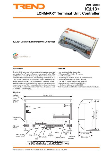
<strong>Data</strong> <strong>Sheet</strong><strong>IQL13+</strong>LONMARK ® Terminal Unit Controller<strong>IQL13+</strong> LONMARK Terminal Unit ControllerDescriptionThe <strong>IQL13+</strong> is a terminal unit controller which can be networkedusing a LONWORKS ® network. It can communicate with other IQLsand LONMARK network devices using the LONWORKS network,and with IQ system networked devices using 3xtend/EINC L orLINC. It has 3 relay outputs (normally to control fan speed), and4 triac outputs (normally to control valves or dampers). It has 3variable resistance inputs of which the first is normally a thermistortemperature sensor.There are also 2 digital inputs for monitoringmanual buttons or alarm contacts; one of these (IN4) can be usedto connect a Room Display.Features• Low cost terminal unit controller.• Fully compatible with the IQ system.• * LONMARK certified.• No binding for network of only IQ system devices.• Non-volatile memory, no battery required.• 230 Vac or 24 Vac input power versions.• Compatible with Room Display (RD-IQL).• * Conforms to LONMARK profile 8501.* Note that LONMARK certification does not apply to custom strategies.Physicalsurfacemounting 4holesdia 6 mm(0.24”)205 mm (8.07”)! hinged frontcover ) 5 JH= JA C O 1,5 A HE= 5127 mm (5”)129 mm (5.08”)AC inputpower24 V auxiliaryoutput supplyrelay outputsDIN rail cliplabeltriacoutputsinputsservice buttonLon OKLEDLONWORKSnetwork59 mm (2.32”)63 mm (2.48”)! 8 = ? !" 8 = ? ! # " $ %" # $ % & ' ! " # $ % & ' " 8 " 8 ! " #+ + + ! " # $ % &5 4 82 1 ' ! ! !<strong>IQL13+</strong> LONMARK Terminal Unit Controller <strong>Data</strong> <strong>Sheet</strong> TA200205 Issue 6, 4/03/20091
<strong>IQL13+</strong><strong>Data</strong> <strong>Sheet</strong>FUNCTIONALITYThe <strong>IQL13+</strong> consists of a generic IQL series shell (core hardware and firmware) with specific additional hardware. It is suppliedcomplete with a pre-programmed strategy which defines its HVAC equipment interaction. If the unit is ordered with a standardstrategy (e.g. <strong>IQL13+</strong>/WR4), the standard generic strategy is installed and configured for the required standard strategy; this canbe changed to one of the other standard strategies using text communications. The generic strategy is defined in the <strong>IQL13+</strong>/xxxStandard Strategies <strong>Data</strong> <strong>Sheet</strong>, TA200284.FIRMWAREThe following modules are available for configuration by terse text comms. They are described in the IQ System LONWORKS ProductsEngineering Manual TE200292.Core modulesAddress module (R); Analogue array (A); Digital array (B)Time (T)Strategy modulesSensor (S), (analogue - thermistor, potentiometer, or fanspeed switch); Sensor (S), (internal); Loop (L); User (U)Logic (G), (combination, timer, hours run)Function (F), (hysteresis, gate, multiplier, adder, A to D,square root, filter, rescale to, comparator)Switch (W); Knob (K); Driver (D), (digital, raise/lower,time prop., multi state relay and cascade relay); DigitalInput (I)IC Comms (N); Plot channel (P); Display (~); Directory (@)CompatibilityThe IQL will identify itself as an IQL to w comms. A 945 shouldbe set up to detect it as an IQ151 V7.AlarmsThe IQ system LONWORKS Products Engineering Manual fullydescribes alarms.The IQL generates network alarms as follows (if appropriatealarm target address and Lan number are set up in addressmodule):“IQL -Rem LAN From yyy on Lan xxx-LON LAN Broken NKBK” - a break in Lan communicationsLON LAN Changed NKCH”- a node has gone from or beenadded to the LanLON LAN OK NKOK”- Lan communications are restored“IQL - Int’wrk From yyy on Lan xxx-LON Iwrk Broken NKBK” - a break in internetworkcommunicationsLON Iwrk Changed NKCH” - a node has gone from or beenadded to the internetworkLON Iwrk OK NKOK”- internetwork communications arerestoredThe IQL generates the following input alarms. They will be sentto Own Lan alarm reporting address and Lan number if these areset up in the address module:Sensor alarms:SENSOR FAIL occurred (OUTL),SENSOR FAIL cleared (COUT),INPUT ERROR occurred (READ),INPUT ERROR cleared (O/K).Digital input alarms:DIGIN OFF occurred (DI=0)DIGIN OFF cleared (CDI0)DIGIN ON occurred (DI=1)DIGIN ON cleared (CDI1)They are same format as IQ alarms except that time and datefields are filled with spaces.2 <strong>IQL13+</strong> LonMark Terminal Unit Controller <strong>Data</strong> <strong>Sheet</strong> TA200205 Issue 6, 4/03/2009
<strong>Data</strong> <strong>Sheet</strong><strong>IQL13+</strong>HARDWAREUnitThe <strong>IQL13+</strong> is a small terminal controller designed for surface orDIN rail mounting either inside or on the side of terminal units. Ithas a plastic housing with a hinged clear polycarbonate terminalcover and 4 point surface mounting.Input PowerThe <strong>IQL13+</strong> has both 230 Vac and 24 Vac input power options./230: This option requires 230 Vac +15% -10%, 50/60 Hz at upto 13 VA, which consists of up to 3VA internal power, plus thepower required by the triac (valve or damper) 24 Vac outputs andthe 24v auxiliary output supply which together require a maximumof 400 mA./24VAC: This option requires 24 Vac ±15%, 50/60 Hz, at upto 12.1 VA, which consists of up to 2.5VA internal power, plusthe power required by the triac (valve or damper) outputs andthe 24v auxiliary output supply which together a maximum of400 mA. The 24 Vac input power neutral must be earthed(grounded) at the transformer secondary. The ac input powerneutral is internally connected to the IQL electronics earth(ground). Several IQLs may be supplied in parallel.The IQL input power earth (ground) terminal is isolated from the inputpower neutral, and is connected to the chassis; this must be separatelyearthed (grounded) locally.!Note that the IQL must be earthed (grounded).(using its supply connector earth, ground,terminal).The internal supply is protected by an internal solid stateself-resetting thermal device rated at 500 mA.Service ButtonThis is used during the installation of the IQL into a LONWORKSnetwork management tool. This is only necessary under conditionsdescribed in the LONWORKS integration section below. During theinstallation process, the tool will request to be informed of thepresence of the IQL; this is done by pressing the ‘service’ button.Pressing the button also generates an alarm message forwardedby the 3xtend/EINC L or LINC to its target alarm address (if setup) which identifies IQL by means of its Neuron ® chip ID; this canbe used as an attribute to find the IQL’s device address and Lannumber.LONWORKSThe integral LONWORKS transceiver uses FTT (or LPT) which hasthe following features:-(1) Use of free bus topology enabling star, bus, or loopwiring simplifies installation and facilitates networkexpansion.(2) The bus uses two wires (twisted pair) which arepolarity independent with no need for screen.(3) The FTT runs at 78 k baud.(4) The FTT LONWORKS may already be present in abuilding, so the IQ system is able to make use of anexisting building bus and hence reduce installationcost.BackupThe data (shell firmware, strategy, parameters, logged data) isstored in flash memory which is non-volatile in the case of powerfailure. The flash memory is only written to at midnight or aftera write to the address module in order to prolong the life of theflash memory. Any changes to sensor or driver types should beterminated by a text comms reset command R(z=1) to immediatelywrite the changes to flash and reset the unit; note that thiscommand clears logged data and sets the time to zero. Any otherparameter changes (other than address module changes andchanges to current time) should be terminated by the text commscommand R(z=0) to immediately write the changes to flash.OutputsRelay Outputs (OUT1, 2, 3 - e.g. fan speed switches)IQL67891011121314OUT1OUT2OUT3terminal numbersTriac Outputs (OUT4, 5, and OUT6, 7 - e.g. raise/lower valves)0 V" 8 = ?" 8 = ?IQL # $ % & 'OUT4COMOUT5OUT6COMOUT724~24~terminal numbersLon OK IndicatorIt flashes approximately every 24 s while the local Lan of IQLsis being built, after which it stays on indicating that the IQL hassuccessfully communicated with at least one other IQ systemdevice on the LONWORKS. If the IQL does not receive any messages(i.e. a deaf IQL), it will flash every second.<strong>IQL13+</strong> LonMark Terminal Unit Controller <strong>Data</strong> <strong>Sheet</strong> TA200205 Issue 6, 4/03/20093
<strong>IQL13+</strong><strong>Data</strong> <strong>Sheet</strong>HARDWARE (continued)InputsIN1 Resistance Input(normally thermistor)IN2 Resistance Input(normally potentiometer)IN3 Resistance InputIN4 Digital InputIN5 Digital Input2122IN1COMIN2COMIN3IN4CIN5Inputs 1, 2, 3Variable resistance (analogue) inputs, 0 to 29 k The use of theinputs is defined by the strategy; the following are examples.Thermistor temperature sensor input (normallyinput 1). Thermistor inputs are scaled for a standard IQsystem thermistor (10 k at 25 °C, 77 °F). Scaling range2.5 °C to 60 °C(36.5 °F to 116 °F). Conversion accuracy±0.25 °C(±0.45 °F) over range (10 to 30 °C, 50 °F to86 °F).Potentiometer input (normally input 2). Scaled forstandard IQ system potentiometer (1 k to 11 k). Apotentiometer input is automatically self calibrating togive 0% to 100% of adjustment over full range ofpotentiometer. If required calibration may be set by turningpotentiometer to both ends of range, and waiting 6 secsat each endpoint.Fan Speed Control input (normally input 3). Inputresistance is set to one of five values by an externalswitch and decoded to give required fan speed selection(Off, Low manual, Medium manual, High manual, andAuto).232425262728terminal numbersIQLDisplayThe RD-IQL/K (Room Display) is a wall mounting temperaturesensor and 3 digit display with control and indication of setpoint.The RD-IQL/KOS also provides an occupation override switchand indication. The RD-IQL/KOSF also provides fan speed controland indication. The RD is connected to IN4. Some IQL configurationparameters must be changed for an IQL to operate with theRD-IQL (see strategy data sheet).Connecting an RD renders some of the normal featuresinoperative:RD-IQL/K: The RD’s potentiometer must be used, not IN2(if a potentiometer is required). A separate sensorconnected to IN1 may be used instead of the RD’s; thisis achieved by maintaining the normal sensor type forIN1. There will be no PIR or pushbutton input. A fan speedswitch connected to IN3 may be used.RD-IQL/KOS: The same as for RD-IQL/K but the /KOSgives use of its pushbutton.RD-IQL/KOSF: The same as for RD-IQL/KOS but the/KOSF gives use of its fan speed switch. A separate fanspeed switch connected to IN3 may be used instead ofthe RD’s; this is achieved by maintaining the normalsensor type for IN3.The SDU-LON (Smart Display Unit) is a wall mountingelectroluminescent display that can be connected to the LONWORKSbus and attached to its IQL. It enables the user to view and adjustselected parameters within the controller. The SDU-LON has areal time clock that can set the controller’s time, it also providesit with a time zone and calendar features (see SDU data sheetTA200559).SensorsThe TB/TS provides a wall mounting thermistor space sensorthat can be connected to the <strong>IQL13+</strong> input 1 (see TB/TS datasheet TA200603). The TB/TS/K also provides setpoint adjustmentto connect to input 2. The TB/TS/KE has the TB/TS/K featuresplus an occupation override pushbutton to connect to input 4.The TB/TS/KEF has the TB/TS/KE features plus a fan speedcontrol switch to connect to input 3.Inputs 4, 5Volt free contact (digital) inputs. 5 Vdc supply via 10 k. Wettingcurrent 0.5 mA. Input 4 provides a TBus connection for use bythe RD-IQL (room display).4 <strong>IQL13+</strong> LonMark Terminal Unit Controller <strong>Data</strong> <strong>Sheet</strong> TA200205 Issue 6, 4/03/2009
<strong>Data</strong> <strong>Sheet</strong><strong>IQL13+</strong>SYSTEMFull system details are covered by IQ System LONWORKS Product Engineering ManualLONWORKS busThe IQL is an IQ controller which uses the LONWORKS bus as itscommunications network. It is LONMARK certified and willcommunicate with other LONMARK devices.LONWORKS IntegrationIn a LONWORKS system consisting only of IQ system devices noLONWORKS installation is required as IQ system LONWORKSproducts self-install. Installation onto a LONWORKS networkmanagement tool is only necessary if it is required to bind LONMARKdevices to the IQL strategy modules, if LINCs, pre-version 3.23,straddle a router, if other devices on the LONWORKS networkhave address conflicts with IQ system LONWORKS devices, or ifLONWORKS routers (e.g. IQLROUTERs) are used on an installedsystem. If one IQ system LONWORKS device is installed, all IQsystem LONWORKS devices must be installed.From a LONWORKS network perspective the IQL is supplied in aconfigured state i.e. it will install on the network with its addressset up and communicate using IQ system communications. It canbe set to an unconfigured state using a LONWORKS ManagementTool.IQL addressThe IQL device and Lan number are set up in the factory on arolling basis, so in a batch of IQLs, each will have a differentfactory address (printed on the unit’s label along with its NeuronID). IQ system LONWORKS devices on the same Lan must be onsame LONWORKS subnet (and hence same side of LONWORKSrouter). An IQL may be re-addressed by terse text comms(IqlTool2 recommended). New addresses should be written onthe unit’s label; a tear-off adhesive label strip with unit ID andaddress information can be used for a paper record e.g. logbook.CommunicationThe 3xtend/EINC L or LINC acts as an interface between the IQsystem Lan and the LONWORKS bus. It enables IQLs to communicatewith IQ system Supervisors by terse text comms and with IQsystem IQs by IC Comms. The 3xtend/EINC L is the preferableinterface, but if the system is installed on a LONWORKS ManagementTool, the LINC must be used. If the IQL is bound to other LONMARKdevices it communicates with them using Network Variables(NVs) as shown in accompanying table. The binding to a variableis done by using both SNVT (standardised network variabletype) and NV name for each variable. All the network variablesare described in the manual TE200292. Those required for theLONMARK node and the LONMARK profile 8501 compatibility areshown in the adjacent table (custom strategies may not havethese variables).IqlTool2IqlTool2 software tool connects directly to the LONWORKS segmentby way of the LCI (LONWORKS Comms Interface) using adaptorcables supplied with the interface.It runs on a PC on which SET v5.1 or greater has been installed.IqlTool2 (SET)LCIIQLLONWORKSnetworkIqlTool2 facilitates mapping the LONWORKS segment, resolvingduplicate addresses on LONWORKS, water balancing (/WR2,/WR4, /WT2, /WT4 only), identifying using service button,associating with SDU-LON, monitoring inputs and exercisingoutputs, setting as a timekeeper, and configuring for RD. Itprovides access to text communications for changing moduleparameters (e.g. knobs, switches, changing a generic strategy).nvnameLONMARKNodeSNVTMandatory Network VariablesnviRequestnvoStatusSNVT_obj_reques tSNVT_obj_statu sOptional Configuration PropertiesnciNetConfignciMajDevVernciMinDevVerSNVT_config_srcSNVT_coun tSNVT_coun tManufacturer Defined SectionnciDomainIndexnciDomainWidenciMsgCodenciBufferSizenviCurrDateTimenviSecurity CodenvoGeneratorLONMARKProfile 8501SNVT_coun tSNVT_lev_discSNVT_coun tSNVT_countSNVT_time_stam pSNVT_coun tSNVT_coun tMandatory Network VariablesnviSpaceTempnvoSpaceTempnvoUnitStatusStrategyVar.SNVT_temp_p K2SNVT_temp_p S1SNVT_hvac_statu sOptional Network VariablesnviSetpointnviSetptOffsetnviOccManCmdnviFanSpeedCmdnvoEffectSetPtnvoEffectOccupnvoFanSpeednvoHeatPrimarynvoCoolPrimarySNVT_temp_p K1SNVT_temp_p K8SNVT_occupancy K6SNVT_temp_p K7SNVT_temp_p S2SNVT_occupancy S3SNVT_switch S6SNVT_lev_percent S4SNVT_lev_percent S5Mandatory Configuration PropertiesnciSndHrtBtnciSetpointsSNVT_time_se cSNVT_temp_setp tOptional Configuration PropertiesManufacturer Defined SectionnvoA7nvoA8nviA19nviA20nviA21nviB18_0nviB18_1nviB18_2nviB18_3nviB18_4nviB18_5nviB18_6nviB18_7nvoB1_0nvoB1_1nvoB1_2nvoB1_3nvoB1_4nvoB1_5nvoB1_6nvoB1_7SNVT_temp_p S7SNVT_temp_p S8SNVT_temp_p K3SNVT_temp_p K4SNVT_temp_p K5SNVT_switch W1SNVT_switch W2SNVT_switch W3SNVT_switch W4SNVT_switch W5SNVT_switch W6SNVT_switch W7SNVT_switch W8SNVT_switchI1SNVT_switch I2SNVT_switch I3SNVT_switch I4SNVT_switch I5SNVT_switch I6SNVT_switch I7SNVT_switch I8Table of Network Variables for <strong>IQL13+</strong>LabelLONWORKS ManagedLONWORKS domainindexLONWORKS domain wideLONWORKS messagecodeRouter buffer sizeRemoteSpaceTem pSpace Tem pRemote SetpointRemote SP OffsetRemote OccRemote Fan SpdSetpointOccupanc yFan SpeedHeating DemandCooling DemandEffect Fan SpeedOCC DeadbndStandby DeadbndNOCC DeadbndO=4Pipe I=2PipeSummer ModeElec DisableO=Water I=Ai rWindow ModeO=Pb I=PIRFrost ConditionRemote Shutdow nFan EnabledUnit OccupiedUnit Unoccupie dUnit in BypassUnit in Standb y<strong>IQL13+</strong> LonMark Terminal Unit Controller <strong>Data</strong> <strong>Sheet</strong> TA200205 Issue 6, 4/03/20095


