M3i.48xx - 16 bit transient recorder up to 180 MS/s
M3i.48xx - 16 bit transient recorder up to 180 MS/s
M3i.48xx - 16 bit transient recorder up to 180 MS/s

Create successful ePaper yourself
Turn your PDF publications into a flip-book with our unique Google optimized e-Paper software.
<strong>M3i.48xx</strong> - <strong>16</strong> <strong>bit</strong> <strong>transient</strong> <strong>recorder</strong> <strong>up</strong> <strong>to</strong> <strong>180</strong> <strong>MS</strong>/s<br />
• Up <strong>to</strong> <strong>180</strong> <strong>MS</strong>/s on one or two channels<br />
• Simultaneously sampling on all channels<br />
• Separate monolithic ADC and amplifier per channel<br />
• 6 input ranges: ±200 mV <strong>up</strong> <strong>to</strong> ±10 V<br />
• Up <strong>to</strong> 2 GSample (4 GByte) on-board memory<br />
• 128 <strong>MS</strong>ample standard memory installed<br />
• Window, re-arm, OR/AND trigger<br />
• Synchronization of <strong>up</strong> <strong>to</strong> 8 cards per system<br />
• Options: Multiple Recording, Timestamps<br />
Speed SNR ENOB<br />
65 <strong>MS</strong>/s <strong>up</strong> <strong>to</strong> TBD dB <strong>up</strong> <strong>to</strong> TBD LSB<br />
105 <strong>MS</strong>/s <strong>up</strong> <strong>to</strong> TBD dB <strong>up</strong> <strong>to</strong> TBD LSB<br />
<strong>180</strong> <strong>MS</strong>/s <strong>up</strong> <strong>to</strong> TBD dB <strong>up</strong> <strong>to</strong> TBD LSB<br />
• 66 MHz 32 <strong>bit</strong> PCI-X interface<br />
• 5V / 3.3V PCI compatible<br />
• 100% compatible <strong>to</strong> conventional PCI > V2.1<br />
• Sustained streaming mode <strong>up</strong> <strong>to</strong> 245 MB/s<br />
• 2,5 GBit x1 PCIe Interface<br />
• Works with x1/x4/x8/x<strong>16</strong>* PCIe slots<br />
• Software compatible <strong>to</strong> PCI<br />
• Sustained streaming mode <strong>up</strong> <strong>to</strong> <strong>16</strong>0 MB/s<br />
Operating Systems<br />
• Windows 2k, XP, Vista, 7<br />
• Linux Kernel 2.4 + 2.6<br />
• Windows/Linux 32 and 64 <strong>bit</strong><br />
Recomended Software<br />
• Visual Basic, Visual C++, Borland<br />
C++ Builder, GNU C++, Borland<br />
Delphi, VB.NET, C#, J#, Python<br />
• SBench 6<br />
Drivers<br />
• MATLAB<br />
• LabVIEW<br />
• LabWindows/CVI<br />
• Agilent VEE<br />
Model 1 channel 2 channels<br />
General Information<br />
M3i.4830 65 <strong>MS</strong>/s The 6 models of the <strong>M3i.48xx</strong> series are designed for the fast and high quality data acquisition.<br />
M3i.4831 65 <strong>MS</strong>/s 65 <strong>MS</strong>/s<br />
Each of the input channels has its own monolithic A/D converter and its own programmable<br />
M3i.4840 105 <strong>MS</strong>/s<br />
input amplifier. This allows <strong>to</strong> record signals simultaneously on both channels with <strong>16</strong> <strong>bit</strong> resolution<br />
without any phase delay between them. The extremely large on-board memory allows long<br />
M3i.4841 105 <strong>MS</strong>/s 105 <strong>MS</strong>/s<br />
M3i.4860 <strong>180</strong> <strong>MS</strong>/s<br />
time recording even with the highest sampling rates. All boards of the <strong>M3i.48xx</strong> series may use<br />
M3i.4861 <strong>180</strong> <strong>MS</strong>/s <strong>180</strong> <strong>MS</strong>/s<br />
the whole installed on-board memory for the currently activated number of channels. A FIFO<br />
mode is also integrated on the board. This allows the acquisition of data continuously for online<br />
processing or for data s<strong>to</strong>rage <strong>to</strong> hard disk.<br />
*Some x<strong>16</strong> PCIe slots are for the use of graphic cards only and can not be used for other cards.<br />
SPECTRUM SYSTEMENTWICKLUNG MICROELECTRONIC GMBH · AHRENSFELDER WEG 13-17 · 22927 GROSSHANSDORF · GERMANY 20.10.10<br />
PHONE: +49 (0)4102-6956-0 · FAX: +49 (0)4102-6956-66 · E-MAIL: info@spec.de · INTERNET: http://www.spectrum-instrumentation.com
Software S<strong>up</strong>port<br />
Windows drivers<br />
The cards are delivered with drivers for Windows 2000, XP,<br />
XP64, Vista and Vista64 as well as Windows 7. Programming examples<br />
for Visual C++, Borland C++ Builder, LabWindows/CVI,<br />
Borland Delphi, Visual Basic, VB.NET, C# and J# are included.<br />
Linux Drivers<br />
All cards are delivered with full Linux s<strong>up</strong>port. Pre compiled<br />
kernel modules are included for the most common<br />
distributions like RedHat, Fedora, Suse or Debian. The<br />
Linux s<strong>up</strong>port includes SMP systems, 32 <strong>bit</strong> and 64 <strong>bit</strong><br />
systems, versatile programming examples for Gnu C++<br />
as well as the possibility <strong>to</strong> get the driver sources for own compilation.<br />
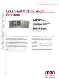
SBench 6<br />
A base licence of SBench 6 the<br />
easy-<strong>to</strong>-use graphical operating<br />
software for the Spectrum cards is<br />
included in the delivery. Using the<br />
base license ist is possible <strong>to</strong> test<br />
the card and <strong>to</strong> show acquired data.<br />
There are also some basic measurement<br />
functions included in the<br />
base license. The card comes with<br />
a demo license for the professional<br />
version giving the user the oportunity <strong>to</strong> test the features of the<br />
professional version with the new hardware. Existing cus<strong>to</strong>mers<br />
have the oportunity <strong>to</strong> request a demo license for the professional<br />
version at Spectrum. The professional version contains several new<br />
measurement functions, FFT, import and exporr (including MATLAB<br />
and ASCII) as well as the streaming modes. The data streaming<br />
modes allow <strong>to</strong> continuously acquire data <strong>to</strong> hard disk. SBench 6<br />
has been optimized <strong>to</strong> handle data files of several GByte. More details<br />
on SBench 6 are found in the dedicated SBench 6 data shett.<br />
The version 6 is running under Windows as well as under Linux<br />
(KDE and GNOME). A test version of SBench 6 is freely available<br />
in the internet. This test version will also operate with demo cards<br />
and can be tested as Professional version without any hardware installed.<br />
Third-party products<br />
A lot of third-party products are s<strong>up</strong>ported as an option. Choose between<br />
LabVIEW, MATLAB and Agilent VEE. All drivers come with<br />
examples and detailed documentation.<br />
Hardware features and options<br />
PCI/PCI-X<br />
The cards with PCI/PCI-X bus<br />
connec<strong>to</strong>r use 32 Bit and <strong>up</strong> <strong>to</strong><br />
66 MHz clock rate for data transfer.<br />
They are 100% compatible<br />
<strong>to</strong> Conventional PCI > V2.1. The<br />
universal interface allows the use<br />
in PCI slots with 5 V I/O and 3.3<br />
V I/O voltages as well as in PCI-<br />
X or PCI 64 slots. The maximum sustained data transfer rate is 245<br />
MByte/s per bus segment.<br />
PCI Express<br />
The cards with PCI Express use a x1<br />
PCIe connec<strong>to</strong>r. They can be used in<br />
PCI Express x1/x4/x8/x<strong>16</strong> slots, except<br />
special graphic card slots, and<br />
are 100% software compatible <strong>to</strong><br />
Conventional PCI > V2.1. The maximum sustained data transfer<br />
rate is <strong>16</strong>0 MByte/s per slot.<br />
SMA connec<strong>to</strong>rs<br />
As an alternative <strong>to</strong> the standard SMB and MMCX connections<br />
the card can also be equipped with SMA connec<strong>to</strong>rs.<br />
The SMA connections are available for the<br />
analog input signals as well as for two of the addi<strong>to</strong>nal<br />
connections. These connections must be defined on the<br />
purchase order and can be a selection of: Trig-In, Trig-<br />
Out, Multi-Purpose X0, Clk-In, Clk-Out.<br />
Input Amplifier<br />
The analog inputs can be adapted<br />
<strong>to</strong> real world signals using a<br />
wide variety of settings that are<br />
individual for each channel. By<br />
using software commands the input<br />
termination can be changed<br />
between 50 Ohm and 1 MOhm, one can select a matching input<br />
range and the signal offset can be compensated by programmable<br />
AC co<strong>up</strong>ling.<br />
Software selectable input path<br />
For each of the analog channels the user has the choice between<br />
two analog input paths. The „Buffered“ path offers the highest flexibility<br />
when it comes <strong>to</strong> input ranges and termination. A software<br />
programmable 50 Ohm and 1 MOhm termination also allows <strong>to</strong><br />
connect standard oscilloscope probes <strong>to</strong> the card. The „50 Ohm“<br />
path on the other hand provides the highest bandwith and the best<br />
signal integrity with a fewer number of input ranges and a fixed 50<br />
Ohm termination.<br />
Software selectable lowpass filter<br />
Each analog channel contains a software selectable low-pass filter<br />
<strong>to</strong> limit the input bandwidth. Reducing the analog input bandwidth<br />
results in a lower <strong>to</strong>tal noise and can be usefull especially with low<br />
voltage input signals.<br />
Au<strong>to</strong>matic on-board calibration<br />
All of the channels are calibrated in fac<strong>to</strong>ry before the board is<br />
shipped. To compensate for different variations like PC power s<strong>up</strong>ply,<br />
temperature and aging, the software driver provides routines<br />
for an au<strong>to</strong>matic onboard offset and gain calibration of all input<br />
ranges of the „Buffered“ path. All the cards contain a high precision<br />
on-board calibration reference.<br />
Digital inputs<br />
This option acquires additional synchronous<br />
digital channels phasestable<br />
with the analog data. A maximum<br />
of 2 additional digital inputs<br />
are available on the front plate of the card using the multi-purpose<br />
I/O lines.<br />
Ring buffer mode<br />
The ring buffer mode is the<br />
standard mode of all oscilloscope<br />
boards. Data is written<br />
in a ring memory of the<br />
board until a trigger event is<br />
detected. After the event the posttrigger values are recorded. Because<br />
of this continuously recording in<strong>to</strong> a ring buffer there are also<br />
samples prior <strong>to</strong> the trigger event visible: Pretrigger = Memsize -<br />
Posttrigger.<br />
FIFO mode<br />
The FIFO mode is designed for continuous data transfer between<br />
measurement board and PC memory (<strong>up</strong> <strong>to</strong> 245 MB/s on a PCI-X
slot, <strong>up</strong> <strong>to</strong> 125 MB/s on a PCI slot and <strong>up</strong> <strong>to</strong> <strong>16</strong>0 MB/s on a PCIe<br />
slot) or hard disk. The control of the data stream is done au<strong>to</strong>matically<br />
by the driver on interr<strong>up</strong>t request. The complete installed onboard<br />
memory is used for buffer data, making the continuous<br />
streaming extremely reliable.<br />
Channel trigger<br />
The data acquisition boards offer a wide variety of trigger modes.<br />
Besides the standard signal checking for level and edge as known<br />
from oscilloscopes it’s also possible <strong>to</strong> define a window trigger. All<br />
trigger modes can be combined with a re-arming mode (for accurate<br />
trigger recognition on noisy signals) the AND/OR conjunction<br />
of different trigger events is possible.<br />
External trigger input<br />
All boards can be triggered using an external analog or digital signal.<br />
It’s possible <strong>to</strong> use positive or negative edge. As two analog<br />
compara<strong>to</strong>rs are used, one can also define a window trigger, a<br />
hysteresis trigger or a re-arm trigger.<br />
Universal Multi-Purpose I/Os<br />
All M3i cards offer two universal multi-purpose I/<br />
O lines, which can be separately programmed as<br />
either input or output. These lines can be used as<br />
additional TTL trigger inputs for more complex trigger<br />
conditions. When used as outputs, these lines<br />
can be used <strong>to</strong> output card status signals like trigger-armed<br />
or <strong>to</strong> output the trigger <strong>to</strong> synchronize<br />
external equipment.<br />
External clock input and output<br />
Using a dedicated connec<strong>to</strong>r a sampling clock can be fed in from<br />
an external system. Additionally it’s also possible <strong>to</strong> output the internally<br />
used sampling clock an a separate connec<strong>to</strong>r <strong>to</strong> synchronize<br />
external equipment <strong>to</strong> this clock.<br />
Reference clock<br />
The option <strong>to</strong> use a precise<br />
external reference clock<br />
(normally 10 MHz) is necessary<br />
<strong>to</strong> synchronize the<br />
board for high-quality measurements<br />
with external equipment (like a signal source). It’s also<br />
possible <strong>to</strong> enhance the quality of the sampling clock in this way.<br />
The driver au<strong>to</strong>matically generates the requested sampling clock<br />
from the fed in reference clock.<br />
Star-Hub<br />
The star-hub is an additional<br />
module allowing the phase stable<br />
synchronisation of <strong>up</strong> <strong>to</strong> 8<br />
boards of a kind in one system.<br />
Independent of the number of<br />
boards there is no phase delay<br />
between all channels. The starhub<br />
distributes trigger and<br />
clock information between all boards. As a result all connected<br />
boards are running with the same clock and the same trigger. All<br />
trigger sources can be combined with a logical OR allowing all<br />
channels of all cards <strong>to</strong> be trigger source at the same time.<br />
Multiple Recording<br />
The Multiple Recording option<br />
allows the recording of<br />
several trigger events with an<br />
extremely short re-arming<br />
time. The hardware doesn’t<br />
need <strong>to</strong> be restarted in between.<br />
The on-board memory is divided in several segments of the<br />
same size. Each of them is filled with data if a trigger event occurs.<br />
Pre- and posttrigger of the segments can be programmed. The number<br />
of acquired segments is only limited by the used memory and<br />
is unlimited when using FIFO mode.<br />
BaseXIO (enhanced timestamps)<br />
The BaseXIO option offers 8 asynchronous<br />
digital I/O lines on the base card,<br />
which are available on a separate bracket<br />
as SMB connec<strong>to</strong>rs. The direction can<br />
be selected by software in gro<strong>up</strong>s of four.<br />
In addition one of the I/O lines can be used as reference clock for<br />
the Timestamp counter.<br />
ABA mode<br />
The optional ABA mode<br />
combines slow continuous<br />
data recording with<br />
fast acquisition on trigger<br />
events. The ABA<br />
mode works like a slow<br />
data logger combined<br />
with a fast digitizer. The<br />
exact position of the trigger events is s<strong>to</strong>red as timestamps in an extra<br />
memory.<br />
Timestamp<br />
The timestamp option writes<br />
the time positions of the trigger<br />
events in an extra memory.<br />
The timestamps are<br />
relative <strong>to</strong> the start of recording,<br />
a defined zero time, externally<br />
synchronised <strong>to</strong> a radio clock, or a GPS receiver. With this<br />
option acquisitions of systems on different locations can be set in a<br />
precise time relation.
Technical Data<br />
Analog Inputs<br />
Clock<br />
Resolution <strong>16</strong> <strong>bit</strong> Internal clock range 10 MHz <strong>to</strong> max (see table below)<br />
Differential non linearity (DNL) TBD Internal clock accuracy max. ± 32 ppm<br />
Integral non linearity (INL) TBD Internal clock set<strong>up</strong> granularity 1 Hz<br />
Programmable input offset not available Clock range gaps (internal and external) none<br />
Connec<strong>to</strong>r (analog inputs) 3 mm SMB male External clock input connec<strong>to</strong>r/co<strong>up</strong>ling MMCX female, AC co<strong>up</strong>led<br />
Crosstalk sine signal ±1V @ 1 MOhm TBD External clock input termination 50 Ohm fixed<br />
Crosstalk sine signal ±5V @ 1 MOhm TBD Reference clock: external clock range ≥ 10.0 MHz and ≤ 1.0 GHz<br />
Crosstalk sine signal ±5V @ 50 Ohm TBD Sampling clock from ref clock range 10 MHz <strong>to</strong> max (see table below)<br />
20 MHz BW Filter Characteristics 3rd order Butterworth Sampling clock from ref clock granularity 1 kHz<br />
External clock delay <strong>to</strong> internal ADC clock 3.7 ns (8.2 ns at synchronized cards)<br />
Input Path 50 ohm path 1 Buffered path 0 External clock input type single-ended, 3.3V LVPECL<br />
Input impedance fixed 50 Ohm 50 Ohm, 1 MOhm||25 pF External clock min input swing 0.3 V peak peak<br />
Max input @ 50 Ohm (> ±1 V range) 6 Vrms 5 Vrms External clock maximum voltage 3.0 V peak peak<br />
Max input @ 50 Ohm (≤ ±1 V range) 2 Vrms 5 Vrms External clock duty cycle requirement 40% <strong>to</strong> 60%<br />
Max input @ 1 MOhm (> ±1 V range) n.a. ±30 V External clock output connec<strong>to</strong>r/co<strong>up</strong>ling MMCX female, AC co<strong>up</strong>led<br />
Max input @ 1 MOhm (≤ ±1 V range) n.a. ±5 V External clock output type single-ended, 3.3V LVPECL<br />
Max DC voltage if AC co<strong>up</strong>ling active ±30 V DC level ±30 V DC level External clock output drive strength Capable of driving 50 ohm load<br />
Relative input stage delay 0 ns 3.8 ns<br />
Input ranges TBD ±200 mV, ±500 mV, ±1 V, Environmental and Physical details<br />
±2 V, ±5 V, ± 10 V<br />
Offset Error after warm-<strong>up</strong> + calibration ≤0.1% of range ≤0.1% of range Dimension (PCB only) 312 mm x 107 mm (full PCI length)<br />
Gain Error after warm-<strong>up</strong> + calibration ≤1.0% of range ≤0.1% of range Width (Standard or star-hub 4) 1 full size slot<br />
Width (star-hub 8)<br />
2 full size slots<br />
Trigger Width (with BaseXIO) 1 full size slots + 1 half size slot<br />
Multiple Recording: re-arming time ≤ 32 Samples Weight (plain card) 320 g<br />
Max Pretrigger at standard mode <strong>up</strong> <strong>to</strong> full memsize Weight (plain card + option SH4) 380 g<br />
Max Pretrigger at Multi and FIFO 8192 Samples as sum of all active channels Weight (plain card + option SH8) 400 g<br />
Internal trigger accuracy 1 Sample Warm <strong>up</strong> time 10 minutes<br />
Channel trigger resolution 10 <strong>bit</strong>s Operating temperature 0°C - 50°C<br />
Trigger output delay 134 sampling clock cycles (after trigger input) S<strong>to</strong>rage temperature -10°C - 70°C<br />
External trigger type (Ext0) Analog window compara<strong>to</strong>r Humidity 10% <strong>to</strong> 90%<br />
Programmable trigger levels (Ext0) 2 levels +/- 5V in steps of 1 mV<br />
Ext. trigger connec<strong>to</strong>r (Ext0) MMCX female PCI / PCI-X specific details<br />
Ext. trigger max voltage 1 MOhm (Ext0) ±30 V PCI / PCI-X bus slot type 32 <strong>bit</strong> 33/66 MHz<br />
Ext. trigger max voltage 50 Ohm (Ext0) 5V rms PCI / PCI-X bus slot compatibility 32/64 <strong>bit</strong>, 33-133 MHz, 3,3 and 5 V I/O<br />
Ext. trigger impedance (Ext0)<br />
50 Ohm / 1 MOhm || 25 pF<br />
External trigger accuracy (All) 1 Sample PCI EXPRESS specific details<br />
Trigger output see multi purpose I/O lines below PCIe slot type x1<br />
PCIe slot compatibility<br />
x1/x4/x8/x<strong>16</strong>*<br />
Power consumption (max speed) PCI / PCI-X PCI EXPRESS *Some x<strong>16</strong> PCIe slots are for graphic cards only and can not be used for other cards.<br />
3,3 V 5 V 3,3 V 12 V<br />
M3i.41x0 (128 <strong>MS</strong> memory) TBD A TBD A TBD A TBD A Software programmable parameters<br />
M3i.41x1 (128 <strong>MS</strong> memory) TBD A TBD A TBD A TBD A Input Ranges (Buffered path) ±200mV, ±500mV, ±1V, ±2V, ±5V, ±10V<br />
M3i.41x1 (2 GS memory), max. power TBD A TBD A TBD A TBD A Input Ranges (50 Ohm path) TBD<br />
Analog input impedance<br />
50 Ohm / 1M Ohm (Buffered path)<br />
Analog input co<strong>up</strong>ling<br />
AC / DC<br />
Max channels with Star-Hub SH4 SH8 Analog bandwidth limit filter on/off<br />
M3i.41x0 4 8 Clock mode Internal, external reference clock, sync<br />
M3i.41x1 8 <strong>16</strong> Trigger mode Ch0, Ch1, Ext0(Analog), Ext1/2(TTL), SW<br />
Enhanced trigger<br />
Window, Re-Arm, Or/And, Delay<br />
BaseXIO (Option) Trigger level (channel) 10 <strong>bit</strong> resolution relating <strong>to</strong> input range<br />
BaseXIO Connec<strong>to</strong>r (extra bracket) 8 x SMB male (8 x MMCX female internal) Trigger level (Ext0) 1 mV resolution: -5000 mV <strong>to</strong> +5000 mV<br />
BaseXIO input TTL compatible: Low ≤ 0.8 V, High ≥ 2.0 V Trigger edge (channel + external) Rising edge, falling edge or both edges<br />
BaseXIO input maximum voltage -0.5 V <strong>up</strong> <strong>to</strong> +5.5 V Trigger delay 0 <strong>to</strong> 32G samples in steps of 8 samples<br />
BaseXIO output levels TTL compatible: Low ≤ 0.4 V, High ≥ 2.4 V External trigger (Ext0) co<strong>up</strong>ling AC/DC<br />
BaseXIO output drive strength 32 mA maximum current External trigger (Ext0) impedance 50 Ohm / 1M Ohm<br />
Multi purpose digital I/O<br />
Memory depth<br />
<strong>16</strong> <strong>up</strong> <strong>to</strong> [installed memory / number of<br />
active channels] in steps of 8<br />
No of multi purpose lines two Posttrigger 8 <strong>up</strong> <strong>to</strong> 4 GSamples in steps of 8<br />
Connec<strong>to</strong>r Type MMCX female Multiple Recording segment size <strong>16</strong> <strong>up</strong> <strong>to</strong>[installed memory / 2 / active<br />
Input: available input signals<br />
Additional TTL trigger, async input<br />
channels] in steps of <strong>16</strong><br />
Input: input impedance 10 k against 3.3 V Multiple Recording pretrigger 8 <strong>up</strong> <strong>to</strong> [8k samples / number of active<br />
channels]<br />
Input: maximum voltage<br />
-0.3 V <strong>up</strong> <strong>to</strong> +5.5 V<br />
Input: input voltage level Low ≤ 0.8 V, High > 2.0 V Certifications, Compliances, Warranty<br />
Output: available output signals trigger, overrange, arm, run, async output EMC Immunity Compliant with CE Mark<br />
Output: output impedance 50 Ohm EMC Emission Compliant with CE Mark<br />
Output: output levels Low ≤ 0.4 V, High ≥ 2.4 V Product warranty 2 years starting with the day of delivery<br />
Output: output type TTL compatible for high-impedance loads Software and firmware <strong>up</strong>dates Life-time, free of charge<br />
Output: output drive strength<br />
Capable of driving 50 Ohm load<br />
Option SMA connec<strong>to</strong>rs<br />
Available signals for SMA XA<br />
Available signals for SMA XB<br />
One of Trig-In, Trig-Out, Multi Purpose X0<br />
One of Clk-In, Clk-Out, Trig-In
M3i.4830 M3i.4831 M3i.4840 M3i.4841 M3i.4860 M3i.4861<br />
max internal clock (1 channel active) 65 <strong>MS</strong>/s 65 <strong>MS</strong>/s 105 <strong>MS</strong>/s 105 <strong>MS</strong>/s <strong>180</strong> <strong>MS</strong>/s <strong>180</strong> <strong>MS</strong>/s<br />
max internal clock (2 channels active) n.a. 65 <strong>MS</strong>/s n.a. 105 <strong>MS</strong>/s n.a. <strong>180</strong> <strong>MS</strong>/s<br />
lower bandwidth limit (DC co<strong>up</strong>ling) 0 Hz 0 HZ 0 Hz 0 Hz 0 Hz 0 Hz<br />
lower bandwidth limit (AC co<strong>up</strong>led, 50 Ohm)
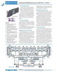
Hardware block diagram
Order Information .<br />
.<br />
PCI/PCI-X Order no. Standard mem 1 channel 2 channels<br />
M3i.4830 128 <strong>MS</strong>ample 65 <strong>MS</strong>/s<br />
M3i.4831 128 <strong>MS</strong>ample 65 <strong>MS</strong>/s 65 <strong>MS</strong>/s<br />
M3i.4840 128 <strong>MS</strong>ample 105 <strong>MS</strong>/s<br />
M3i.4841 128 <strong>MS</strong>ample 105 <strong>MS</strong>/s 105 <strong>MS</strong>/s<br />
M3i.4860 128 <strong>MS</strong>ample <strong>180</strong> <strong>MS</strong>/s<br />
M3i.4861 128 <strong>MS</strong>ample <strong>180</strong> <strong>MS</strong>/s <strong>180</strong> <strong>MS</strong>/s<br />
PCI Express Order no. Standard mem 1 channel 2 channels<br />
M3i.4830-exp 128 <strong>MS</strong>ample 65 <strong>MS</strong>/s<br />
M3i.4831-exp 128 <strong>MS</strong>ample 65 <strong>MS</strong>/s 65 <strong>MS</strong>/s<br />
M3i.4840-exp 128 <strong>MS</strong>ample 105 <strong>MS</strong>/s<br />
M3i.4841-exp 128 <strong>MS</strong>ample 105 <strong>MS</strong>/s 105 <strong>MS</strong>/s<br />
M3i.4860-exp 128 <strong>MS</strong>ample <strong>180</strong> <strong>MS</strong>/s<br />
M3i.4861-exp 128 <strong>MS</strong>ample <strong>180</strong> <strong>MS</strong>/s <strong>180</strong> <strong>MS</strong>/s<br />
Memory Order no. Option<br />
M3i.xxxx-256<strong>MS</strong> Memory <strong>up</strong>grade <strong>to</strong> 256 <strong>MS</strong>ample (512 MB) <strong>to</strong>tal memory<br />
M3i.xxxx-512<strong>MS</strong> Memory <strong>up</strong>grade <strong>to</strong> 512 <strong>MS</strong>ample (1 GB) <strong>to</strong>tal memory<br />
M3i.xxxx-1GS<br />
Memory <strong>up</strong>grade <strong>to</strong> 1 GSample (2 GB) <strong>to</strong>tal memory<br />
M3i.xxxx-2GS<br />
Memory <strong>up</strong>grade <strong>to</strong> 2 GSample (4 GB) <strong>to</strong>tal memory<br />
Options Order no. Option<br />
M3i.xxxx-mr<br />
Option Multiple Recording<br />
M3i.xxxx-mt<br />
Option pack including Multiple Recording, Timestamp<br />
M3i.xxxx-mtab<br />
M3i.xxxx-SH4<br />
M3i.xxxx-SH8<br />
M3i.xxxx-bxio<br />
M3i.xxxx-SMA<br />
M3i-<strong>up</strong>grade<br />
Cables Order no. Option<br />
Cab-1m-9m-80<br />
Cab-1m-9f-80<br />
Cab-1m-9m-200<br />
Cab-1m-9f-200<br />
Cab-1m-9f-5<br />
Cab-1m-3mA-80<br />
Cab-1m-3fA-80<br />
Cab-1m-3mA-200<br />
Cab-1m-3fA-200<br />
Cab-3f-9m-80<br />
Cab-3f-9f-80<br />
Cab-3f-3mA-80<br />
Cab-3f-3fA-80<br />
Cab-3f-3f-80<br />
Cab-3f-9m-200<br />
Cab-3f-9f-200<br />
Cab-3f-9f-5<br />
Cab-3f-3mA-200<br />
Cab-3f-3fA-200<br />
Cab-3f-3f-200<br />
Cab-3mA-9m-80<br />
Cab-3mA-9f-80<br />
Cab-3mA-9m-200<br />
Cab-3mA-9f-200<br />
Drivers Order no. Option<br />
M3i.xxxx-ml<br />
<strong>M3i.48xx</strong>-lv<br />
<strong>M3i.48xx</strong>-vee<br />
Option pack including Multiple Recording, Timestamp, ABA mode<br />
Synchronization Star-Hub for <strong>up</strong> <strong>to</strong> 4 cards, only 1 slot width<br />
Synchronization Star-Hub for <strong>up</strong> <strong>to</strong> 8 cards, 2 slots width<br />
Option BaseXIO: 8 digital I/O lines usable as asynchronous I/O and timestamp ref-clock, additional<br />
bracket with 8 SMB connec<strong>to</strong>rs<br />
Option SMA connections for analog inputs + two signals of Clock-In, Clock-Out, Trig-In, Trig-Out, X0<br />
Upgrade for M3i.xxxx: later installation of option -bxio or SMA connec<strong>to</strong>rs<br />
Adapter cable MMCX male <strong>to</strong> BNC male, 80 cm (for all other signals)<br />
Adapter cable MMCX male <strong>to</strong> BNC female, 80 cm (for all other signals)<br />
Adapter cable MMCX male <strong>to</strong> BNC male, 200 cm (for all other signals)<br />
Adapter cable MMCX male <strong>to</strong> BNC female, 200 cm (for all other signals)<br />
Adapter cable MMCX male <strong>to</strong> BNC female, 5 cm (short cable especially for oscilloscope probes)<br />
Adapter cable MMCX male <strong>to</strong> SMA male, 80 cm (for all other signals)<br />
Adapter cable MMCX male <strong>to</strong> SMA female, 80 cm (for all other signals)<br />
Adapter cable MMCX male <strong>to</strong> SMA male, 200 cm (for all other signals)<br />
Adapter cable MMCX male <strong>to</strong> SMA female, 200 cm (for all other signals)<br />
Adapter cable SMB female <strong>to</strong> BNC male, 80 cm (for analog inputs)<br />
Adapter cable SMB female <strong>to</strong> BNC female, 80 cm (for analog inputs)<br />
Adapter cable SMB female <strong>to</strong> SMA male, 80 cm (for analog inputs)<br />
Adapter cable SMB female <strong>to</strong> SMA female, 80 cm (for analog inputs)<br />
Adapter cable SMB female <strong>to</strong> SMB female, 80 cm (for analog inputs)<br />
Adapter cable SMB female <strong>to</strong> BNC male, 200 cm (for analog inputs)<br />
Adapter cable SMB female <strong>to</strong> BNC female, 200 cm (for analog inputs)<br />
Adapter cable SMB female <strong>to</strong> BNC female, 5 cm (short cable especially for oscilloscopes probes)<br />
Adapter cable SMB female <strong>to</strong> SMA male, 200 cm (for analog inputs)<br />
Adapter cable SMB female <strong>to</strong> SMA female, 200 cm (for analog inputs)<br />
Adapter cable SMB female <strong>to</strong> SMB female, 200 cm (for analog inputs)<br />
Adapter cable SMA male <strong>to</strong> BNC male, 80 cm (for SMA option)<br />
Adapter cable SMA male <strong>to</strong> BNC female, 80 cm (for SMA option)<br />
Adapter cable SMA male <strong>to</strong> BNC male, 200 cm (for SMA option)<br />
Adapter cable SMA male <strong>to</strong> BNC female, 200 cm (for SMA option)<br />
MATLAB driver for all M3i cards<br />
LabVIEW driver for all <strong>M3i.48xx</strong> cards<br />
Agilent VEE driver for all <strong>M3i.48xx</strong> cards<br />
SBench6<br />
Order no.<br />
SBench6<br />
SBench6-Pro<br />
SBench6-Multi<br />
Volume Licenses<br />
Base version which s<strong>up</strong>port standard mode for one card<br />
Professional version for one card: FIFO mode, export/import, calculation functions<br />
Option multiple cards: needs Professional version. Handles multiple synchronized cards<br />
in one system.<br />
Please ask Spectrum for details.<br />
Technical changes and printing errors possible