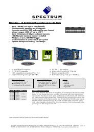
M2i.60xx - 14 bit 125 MS/s Arbitrary Waveform Generator
M2i.60xx - 14 bit 125 MS/s Arbitrary Waveform Generator
M2i.60xx - 14 bit 125 MS/s Arbitrary Waveform Generator

Create successful ePaper yourself
Turn your PDF publications into a flip-book with our unique Google optimized e-Paper software.
<strong>M2i.60xx</strong> - <strong>14</strong> <strong>bit</strong> <strong>125</strong> <strong>MS</strong>/s Ar<strong>bit</strong>rary <strong>Waveform</strong> <strong>Generator</strong><br />
• Fast <strong>14</strong> <strong>bit</strong> ar<strong>bit</strong>rary waveform generator<br />
• 1, 2 or 4 channels with 20 <strong>MS</strong>/s, 60 <strong>MS</strong>/s or <strong>125</strong> <strong>MS</strong>/s<br />
• Simultaneous generation on all channels<br />
• Output up to ± 3 V in 50 Ohm<br />
• Amplifier option available for ±10 V<br />
• Offset and amplitude programmable<br />
• 3 software selectable filters<br />
• Up to 2 GSamples on-board memory<br />
• 128 <strong>MS</strong>ample standard memory installed<br />
• FIFO mode continuous streaming output<br />
• Synchronization of up to 16 cards per system and up to 271 cards with system sync<br />
• Options: Multiple Replay, Gated Replay, BaseXIO, Digital Outputs, Amplifier<br />
• 66 MHz 32 <strong>bit</strong> PCI-X interface<br />
• 5V / 3.3V PCI compatible<br />
• 100% compatible to conventional PCI > V2.1<br />
• Sustained streaming mode up to 245 MB/s<br />
• 2,5 GBit x1 PCIe Interface<br />
• Works with x1/x4/x8/x16* PCIe slots<br />
• Software compatible to PCI<br />
• Sustained streaming mode up to 160 MB/s<br />
Operating Systems<br />
• Windows 2k, XP, Vista<br />
• Linux Kernel 2.4 + 2.6<br />
• Both 32 and 64 <strong>bit</strong><br />
Recomended Software<br />
• Visual Basic, Visual C++, Borland<br />
C++ Builder, GNU C++, Borland<br />
Delphi, .VB.NET, C#, J#<br />
• SBench, SPviewIT<br />
Drivers<br />
• MATLAB<br />
• LabVIEW, LabWindows<br />
• DASYLab<br />
• Agilent VEE<br />
Model 1 channel 2 channels 4 channels<br />
General Information<br />
M2i.6011 20 <strong>MS</strong>/s 20 <strong>MS</strong>/s The <strong>M2i.60xx</strong> series offers 8 different versions of ar<strong>bit</strong>rary waveform generators<br />
M2i.6012 20 <strong>MS</strong>/s 20 <strong>MS</strong>/s 20 <strong>MS</strong>/s<br />
for the PCI/PCI-X bus and PCI Express. With these boards it is possible to generate<br />
M2i.6021 60 <strong>MS</strong>/s 60 <strong>MS</strong>/s<br />
free definable waveforms on several channels synchronously. With one of the synchronization<br />
options the setup of synchronous multi channel systems is possible. It<br />
M2i.6022 60 <strong>MS</strong>/s 60 <strong>MS</strong>/s 60 <strong>MS</strong>/s<br />
M2i.6030 <strong>125</strong> <strong>MS</strong>/s<br />
is also possible to combine the ar<strong>bit</strong>rary waveform generator with other boards of<br />
M2i.6031 <strong>125</strong> <strong>MS</strong>/s <strong>125</strong> <strong>MS</strong>/s<br />
M2i.6033 <strong>125</strong> <strong>MS</strong>/s 60 <strong>MS</strong>/s<br />
the M2i product family like analog acquisition or digital I/O boards. With the up<br />
M2i.6034 <strong>125</strong> <strong>MS</strong>/s <strong>125</strong> <strong>MS</strong>/s 60 <strong>MS</strong>/s<br />
to 2 GSample large on-board memory long waveforms can be generated even<br />
with high sampling rates. All boards of the <strong>M2i.60xx</strong> series may use the whole<br />
installed on-board memory completely for the currently activated number of channels.<br />
The memory can also be used as a FIFO buffer to make continuously data<br />
transfer from PC memory or hard disk.<br />
*Some x16 PCIe slots are for the use of graphic cards only and can not be used for other cards.<br />
SPECTRUM SYSTEMENTWICKLUNG MICROELECTRONIC GMBH · AHRENSFELDER WEG 13-17 · 22927 GROSSHANSDORF · GERMANY 29.10.09<br />
PHONE: +49 (0)4102-6956-0 · FAX: +49 (0)4102-6956-66 · E-MAIL: info@spec.de · INTERNET: http://www.spectrum-instrumentation.com
Software Support<br />
Windows drivers<br />
The cards are delivered with drivers for Windows 2000, XP,<br />
XP64, Vista and Vista64. Programming examples for Visual C++,<br />
Borland C++ Builder, LabWindows/CVI, Borland Delphi, Visual<br />
Basic, VB.NET, C# and J# are included.<br />
Linux Drivers<br />
All cards are delivered with full Linux support. Pre compiled<br />
kernel modules are included for the most common<br />
distributions like RedHat, Fedora, Suse or Debian. The<br />
Linux support includes SMP systems, 32 <strong>bit</strong> and 64 <strong>bit</strong><br />
systems, versatile programming examples for Gnu C++<br />
as well as the possibility to get the driver sources for own compilation.<br />
SPEasy<strong>Generator</strong><br />
For a fast start with the hardware the<br />
simple signal generation software<br />
SPEasy<strong>Generator</strong> is included in the delivery.<br />
This software allows to generator<br />
simple signal shapes like sine, triangle<br />
or rectangle with programmable frequency,<br />
amplitude and phase. SPEasy-<br />
<strong>Generator</strong> is also available as LabWindows source code.<br />
SBench<br />
A full licence of SBench the easy-to-use graphical operating software<br />
for the Spectrum cards is included in the delivery. The version<br />
6 is running under Windows as well as under Linux (KDE and<br />
GNOME).<br />
Third-party products<br />
A lot of third-party products are supported as an option. Choose between<br />
LabVIEW, MATLAB, DASYLab and Agilent VEE. All drivers<br />
come with examples and detailed documentation.<br />
MI Software compatibility layer<br />
To allow an easy change from MI cards to the new M2i cards for<br />
existing software a special software compatibility layer is delivered<br />
with the cards. This DLL converts MI calls to M2i calls and simulates<br />
a MI card in the software.<br />
Hardware features and options<br />
PCI/PCI-X<br />
The cards with PCI/PCI-X bus<br />
connector use 32 Bit and up to<br />
66 MHz clock rate for data transfer.<br />
They are 100% compatible<br />
to Conventional PCI > V2.1. The<br />
universal interface allows the use<br />
in PCI slots with 5 V I/O and 3.3<br />
V I/O voltages as well as in PCI-<br />
X or PCI 64 slots. The maximum sustained data transfer rate is 245<br />
MByte/s per bus segment.<br />
PCI Express<br />
160 MByte/s per slot.<br />
The cards with PCI Express use a x1<br />
PCIe connector. They can be used in<br />
PCI Express x1/x4/x8/x16 slots, except<br />
special graphic card slots, and<br />
are 100% software compatible to<br />
Conventional PCI > V2.1. The maximum<br />
sustained data transfer rate is<br />
FIFO mode<br />
The FIFO mode is designed for continuous data transfer between<br />
measurement board and PC memory or hard disk. The control of<br />
the data stream is done automatically by the driver on interrupt request.<br />
The complete installed on-board memory is used for buffer<br />
data, making the continuous streaming extremely reliable.<br />
External trigger I/O<br />
All digital boards can be triggered using an additional external TTL<br />
signal per acquisition module. It’s possible to use positive or negative<br />
edge also in combination with a programmable pulse width.<br />
An internally recognized trigger event can - when activated by software<br />
- be routed to the trigger output connector to start external instruments.<br />
Pulse width<br />
Defines the minimum or maximum width that a trigger pulse must<br />
have to generate a trigger event. Pulse width can be combined with<br />
channel trigger, pattern trigger and external trigger.<br />
Multiple Replay<br />
The Multiple Replay option allows<br />
the fast repetition output<br />
on several trigger events without<br />
restarting the hardware.<br />
With this option very fast repetition<br />
rates can be achieved.<br />
The on-board memory is divided in several segments of same size.<br />
Each of them is generated if a trigger event occurs.<br />
Gated Replay<br />
The Gated Sampling option<br />
allows data replay controlled<br />
by an external gate signal.<br />
Data is only replayed if the<br />
gate signal has a programmed<br />
level.<br />
Digital outputs<br />
This option outputs additional<br />
synchronous digital channels<br />
phase-stable with the analog data.<br />
When this option is installed<br />
there are 2 additional digital outputs<br />
for every analog D/A channel.<br />
External clock I/O<br />
Using a dedicated line a sampling clock can be fed in from an external<br />
system. It’s also possible to output the internally used sampling<br />
clock to synchronize external equipment to this clock.<br />
Reference clock<br />
The option to use a precise<br />
external reference clock<br />
(normally 10 MHz) is necessary<br />
to synchronize the<br />
board for high-quality measurements<br />
with external equipment (like a signal source). It’s also<br />
possible to enhance the quality of the sampling clock in this way.<br />
The driver automatically generates the requested sampling clock<br />
from the fed in reference clock.<br />
Singleshot output<br />
When singleshot output is activated the data of the on-board memory<br />
is replayed exactly one time. As trigger source one can use the<br />
external TTL trigger or the software trigger.
Repeated output<br />
When repeated output is used the data of the on-board memory is<br />
replayed continuously until a stop command is executed or N times.<br />
As trigger source one can use the external TTL trigger or the software<br />
trigger.<br />
Single Restart replay<br />
When this mode is activated the data of the on-board memory will<br />
be replayed once after each trigger event. Trigger source one can<br />
use the external TTL or software trigger.<br />
±10 V Amplifier<br />
The amplifier board allows the output of ±10 V on<br />
up to four channels without software modification.<br />
The standard outputs of the card are amplified by<br />
factor 3.33. The amplifier which has 30 MHz bandwidth<br />
has an output impedance of 50 Ohm. This allows<br />
±10 V with high impedance termination or ±5<br />
V with 50 ohm termination.<br />
Star-Hub<br />
The star-hub is an additional<br />
module allowing the phase stable<br />
synchronisation of up to 16<br />
boards in one syste,. Independent<br />
of the number of boards<br />
there is no phase delay between<br />
all channels. The starhub<br />
distributes trigger and<br />
clock information between all boards. As a result all connected<br />
boards are running with the same clock and the same trigger. All<br />
trigger sources can be combined with OR/AND allowing all channels<br />
of all cards to be trigger source at the same time. The star-hub<br />
is available as 5 card and 16 card version. The 5 card version<br />
doesn’t need an extra slot.<br />
271 synchronous cards with theSystem Star-Hub<br />
With the help<br />
of multiple system<br />
star-hubs it<br />
is possible to<br />
link up to 17<br />
system phase<br />
synchronous<br />
with each other.<br />
Each system can then contain up to 16 cards (master only 15).<br />
In total 271 cards can be used fully synchronously in a bunch of<br />
systems. One master system distributes clock and trigger signal to<br />
all connected slave systems.<br />
BaseXIO (enhanced trigger)<br />
The BaseXIO option offers 8 asynchronous<br />
digital I/O lines on the base card.<br />
The direction can be selected by software<br />
in groups of four. Two of these lines can<br />
also be used as additional external trigger<br />
sources. This allows the building of complex trigger conjunctions<br />
with external gated triggers as well as AND/OR conjunction<br />
of multiple external trigger sources like, for example, the picture<br />
and row synchronisation of video signals. In addition one of the I/<br />
O lines can be used as reference clock for the Timestamp counter.
Technical Data<br />
Analog Outputs<br />
Clock<br />
Resolution <strong>14</strong> <strong>bit</strong> Internal clock range (PLL mode) 1 kS/s to max (see table below)<br />
INL, Integral linearity (DAC only) ± 1.5 LSB typ. Internal clock accuracy 20 ppm<br />
DNL, Differential linearity (DAC only) ± 1.0 LSB typ. Internal clock: max. jitter in PLL mode TBD<br />
Output resistance < 1 Ohm Internal clock: max. jitter in quartz mode TBD<br />
Max output swing in 50 Ohm ± 3 V (offset + amplitude) Internal clock setup granularity (≤ 100 M) ≤1% of range (100M, 10M, 1M, 100k,...)<br />
Max slew rate (no filter) > 0.9 V/ns Internal clock setup granularity example range 1M to 10M: stepsize ≤ 100k<br />
Crosstalk @ 1 MHz signal ±3 V < -80 dB Reference clock: external clock range ≥ 1.0 MHz and ≤ <strong>125</strong>.0 MHz<br />
Output accuracy < 1% External clock range DC to max (see table below)<br />
Connector (analog and trigger/clock) 3 mm SMB male External clock delay to internal clock 5.4 ns<br />
External clock type<br />
3.3V LVTTL compatible<br />
Trigger External clock input Low ≤ 0.8 V, High ≥ 2.0 V, duty 45% - 55%<br />
Multi, Gate: re-arming time 2.4 V<br />
Connector (digital outputs)<br />
40 pole half pitch (Hirose FX2 series)<br />
Environmental and Physical details<br />
Dimension (PCB only) 312 mm x 107 mm (full PCI length) Output Delays<br />
Width (Standard or star-hub 5) 1 full size slot Trigger to 1st sample 15/16 clocks (2/1 channel/module)<br />
Width (star-hub 16) 2 full size slots Gate end to last replayed sample 15/16 clocks (2/1 channel/module)<br />
Width (with digital inputs) 1 full size slots + 1 half size slot Gate end alignement 2 samples (1 ch), 1 sample (2 or 4 ch)<br />
Weight<br />
(depending on options/channels)<br />
290g (2 ch) up to 460g (4 ch + dig + sh)<br />
BaseXIO (Option)<br />
Warm up time 10 minutes BaseXIO Connector (extra bracket) 8 x SMB (8 x MMCX internal)<br />
Operating temperature 0°C - 50°C BaseXIO input TTL compatible: Low ≤ 0.8 V, High ≥ 2.0 V<br />
Storage temperature -10°C - 70°C BaseXIO input maximum voltage -0.5 V up to +4.0 V (internally clamped to<br />
Humidity 10% to 90%<br />
3.3V, 100 mA max. clamping current)<br />
BaseXIO output levels<br />
TTL compatible: Low ≤ 0.4 V, High ≥ 2.4 V<br />
PCI / PCI-X specific details<br />
PCI / PCI-X bus slot type 32 <strong>bit</strong> 33/66 MHz Software programmable parameters<br />
PCI / PCI-X bus slot compatibility 32/64 <strong>bit</strong>, 33-133 MHz, 3,3 V and 5 V I/O Output amplitude ±100 mV up to ±3 V in 1 mV steps<br />
(Amp option: ±333 mV up to ±10 V)<br />
PCI EXPRESS specific details Output offset ±3 V selectable in 1 mV steps (Amp otpion:<br />
PCIe slot type<br />
x1<br />
±10 V in 3 mV steps)<br />
PCIe slot compatibility x1/x4/x8/x16* Filters no filter or one of 3 different filters as<br />
*Some x16 PCIe slots are for graphic cards only and can not be used for other cards.<br />
defined in technical data section<br />
Mode<br />
Singleshot, Repeated Replay, Single Restart<br />
Max channels with Star-Hub SH5 SH16 SSHS5 SSHS16 Clock mode Int. PLL, int. quartz, ext. clock, ext. divided,<br />
M2i.6030 5 16 85 271<br />
ext. reference clock, sync<br />
M2i.60x1, 60x3 10 32 170 542 Clock impedance 50 Ohm / high impedance (> 4kOhm)<br />
M2i.60x2, 60x4 20 64 340 1084 Trigger impedance 50 Ohm / high impedance (> 4kOhm)<br />
Trigger mode<br />
external TTL, software, pulsewidth, Or/<br />
Power consumption (max speed) PCI / PCI-X PCI EXPRESS<br />
And, Delay<br />
3,3 V 5 V 3,3 V 12 V Trigger edge Rising edge, falling edge, both edges<br />
M2i.6030 (128 <strong>MS</strong> memory) 2.6 A 0.4 A 0.4 A 0.9 A Trigger pulse width 0 to [64k - 1] samples in steps of 1 sample<br />
M2i.60x1/M2i.60x3 (128 <strong>MS</strong> mem.) 2.8 A 0.7 A 0.4 A 1.1 A Trigger delay 0 to [64k - 1] samples in steps of 1 sample<br />
M2i.60x2/M2i.60x4 (128 <strong>MS</strong> mem.) 3.2 A 1.1 A 0.4 A 1.2 A Memory depth 8 up to [installed memory / number of<br />
M2i.6034 (2 GS memory), max. power 4.9 A 1.1 A 0.4 A 1.7 A<br />
active channels] in steps of 4<br />
Multiple Replay segment size<br />
8 up to[installed memory / 2 / active channels]<br />
in steps of 4<br />
Certifications, Compliances, Warranty<br />
EMC Immunity Compliant with CE Mark Sync clock divider 2 up to [8k - 2] in steps of 2<br />
EMC Emission Compliant with CE Mark Channel selection 1, 2, 4<br />
Product warranty<br />
2 years starting with the day of delivery<br />
Software and firmware updates Life-time, free of charge
Clock and Filter<br />
M2i.6011<br />
M2i.6012<br />
M2i.6021<br />
M2i.6022<br />
M2i.6030<br />
M2i.6033<br />
M2i.6031<br />
M2i.6034<br />
max internal clock 20 <strong>MS</strong>/s 62.5 <strong>MS</strong>/s <strong>125</strong> <strong>MS</strong>/s <strong>125</strong> <strong>MS</strong>/s<br />
max external clock 20 <strong>MS</strong>/s 62.5 <strong>MS</strong>/s <strong>125</strong> <strong>MS</strong>/s <strong>125</strong> <strong>MS</strong>/s<br />
-3 dB bandwidth no filter > 10 MHz > 30 MHz > 60 MHz > 60 MHz<br />
Filter 3: Characteristics 4th order Butterworth 5th order Butterworth<br />
Filter 3: -3 dB bandwidth 5 MHz 10 MHz 25 MHz 25 MHz<br />
Filter 2: Characteristics 4th order Butterworth 4th order Butterworth<br />
Filter 2: -3 dB bandwidth 1 MHz 2 MHz 5 MHz 5 MHz<br />
Filter 1: Characteristics 4th order Butterworth 4th order Butterworth<br />
Filter 1: -3 dB bandwidth 100 kHz 200 kHz 500 kHz 500 kHz<br />
Dynamic Parameters<br />
M2i.6011<br />
M2i.6012<br />
M2i.6011<br />
M2i.6012<br />
M2i.6011<br />
M2i.6012<br />
M2i.6021<br />
M2i.6022<br />
M2i.6021<br />
M2i.6022<br />
M2i.6030<br />
M2i.6031<br />
M2i.6033<br />
M2i.6034<br />
M2i.6030<br />
M2i.6031<br />
M2i.6033<br />
M2i.6034<br />
M2i.6030<br />
M2i.6031<br />
M2i.6033<br />
M2i.6034<br />
M2i.6030<br />
M2i.6031<br />
M2i.6033<br />
M2i.6034<br />
Test - Samplerate 20 <strong>MS</strong>/s 20 <strong>MS</strong>/s 20 <strong>MS</strong>/s 60 <strong>MS</strong>/s 60 <strong>MS</strong>/s 62.5 <strong>MS</strong>/s 62.5 <strong>MS</strong>/s <strong>125</strong> <strong>MS</strong>/s <strong>125</strong> <strong>MS</strong>/s<br />
Output Frequency 80 kHz 800 kHz 4 MHz 170 kHz 1.7 MHz 400 kHz 4 MHz 400 kHz 4 MHz<br />
Output Level ±2 V ±2 V ±2 V ±2 V ±2 V ±2 V ±2 V ±2 V ±2 V<br />
Used Filter 100 kHz 1 MHz 5 MHz 200 kHz 2 MHz 500 kHz 5 MHz 500 kHz 5 MHz<br />
SNR (typ) > 61.5 dB > 60.2 dB > 54.5 dB > 61.5 dB > 59.5 dB > 61.5 dB > 55.0 dB > 61.0 dB > 56.0 dB<br />
THD (typ) < -70.4 dB < -67.5 dB < -45.0 dB < -72.7 dB < -62.5 dB < -71.5 dB < -55.6 dB < -71.5 dB < -56.0 dB<br />
SFDR (typ), excl harm. > 85.5 dB > 72.0 dB > 60.0 dB > 81.5 dB > 68.5 dB > 82.8 dB > 66.5 dB > 72.0 dB > 67.0 dB<br />
Dynamic parameters are measured at the given output level and 50 Ohm termination with a high resolution data acquisition card and are calculated from the spectrum. The sample rate<br />
that is selected is the maximum possible one. All available channels are activated for the tests. SNR and SFDR figures may differ depending on the quality of the used PC. SNR = Signal to<br />
Noise Ratio, THD = Total Harmonic Distortion, SFDR = Spurious Free Dynamic Range<br />
Hardware block diagram
Order Information .<br />
PCI/PCI-X Order no. Standard mem 1 channel 2 channels 4 channels<br />
M2i.6011 128 <strong>MS</strong>ample 20 <strong>MS</strong>/s 20 <strong>MS</strong>/s<br />
M2i.6012 128 <strong>MS</strong>ample 20 <strong>MS</strong>/s 20 <strong>MS</strong>/s 20 <strong>MS</strong>/s<br />
M2i.6021 128 <strong>MS</strong>ample 60 <strong>MS</strong>/s 60 <strong>MS</strong>/s<br />
M2i.6022 128 <strong>MS</strong>ample 60 <strong>MS</strong>/s 60 <strong>MS</strong>/s 60 <strong>MS</strong>/s<br />
M2i.6030 128 <strong>MS</strong>ample <strong>125</strong> <strong>MS</strong>/s<br />
M2i.6031 128 <strong>MS</strong>ample <strong>125</strong> <strong>MS</strong>/s <strong>125</strong> <strong>MS</strong>/s<br />
M2i.6033 128 <strong>MS</strong>ample <strong>125</strong> <strong>MS</strong>/s 60 <strong>MS</strong>/s<br />
M2i.6034 128 <strong>MS</strong>ample <strong>125</strong> <strong>MS</strong>/s <strong>125</strong> <strong>MS</strong>/s 60 <strong>MS</strong>/s<br />
PCI Express Order no. Standard mem 1 channel 2 channels 4 channels<br />
M2i.6011-exp 128 <strong>MS</strong>ample 20 <strong>MS</strong>/s 20 <strong>MS</strong>/s<br />
M2i.6012-exp 128 <strong>MS</strong>ample 20 <strong>MS</strong>/s 20 <strong>MS</strong>/s 20 <strong>MS</strong>/s<br />
M2i.6021-exp 128 <strong>MS</strong>ample 60 <strong>MS</strong>/s 60 <strong>MS</strong>/s<br />
M2i.6022-exp 128 <strong>MS</strong>ample 60 <strong>MS</strong>/s 60 <strong>MS</strong>/s 60 <strong>MS</strong>/s<br />
M2i.6030-exp 128 <strong>MS</strong>ample <strong>125</strong> <strong>MS</strong>/s<br />
M2i.6031-exp 128 <strong>MS</strong>ample <strong>125</strong> <strong>MS</strong>/s <strong>125</strong> <strong>MS</strong>/s<br />
M2i.6033-exp 128 <strong>MS</strong>ample <strong>125</strong> <strong>MS</strong>/s 60 <strong>MS</strong>/s<br />
M2i.6034-exp 128 <strong>MS</strong>ample <strong>125</strong> <strong>MS</strong>/s <strong>125</strong> <strong>MS</strong>/s 60 <strong>MS</strong>/s<br />
Memory Order no. Option<br />
M2i.xxxx-256<strong>MS</strong> Memory upgrade to 256 <strong>MS</strong>ample (512 MB) total memory<br />
M2i.xxxx-512<strong>MS</strong> Memory upgrade to 512 <strong>MS</strong>ample (1 GB) total memory<br />
M2i.xxxx-1GS<br />
Memory upgrade to 1 GSample (2 GB) total memory<br />
M2i.xxxx-2GS<br />
Memory upgrade to 2 GSample (4 GB) total memory<br />
Options Order no. Option<br />
M2i.xxxx-mr<br />
Option Multiple Replay<br />
M2i.xxxx-gs<br />
Option Gated Replay<br />
<strong>M2i.60xx</strong>-dig<br />
Additonal synchronous digital outputs (2 per analog channel) including Cab-d40-idc-100<br />
M2i.xxxx-SH5 (1)<br />
M2i.xxxx-SH16 (1)<br />
M2i.xxxx-SSHM (1)<br />
M2i.xxxx-SSHS5 (1)<br />
M2i.xxxx-SSHS16 (1)<br />
MI.6xxx-1Amp<br />
MI.6xxx-2Amp<br />
MI.6xxx-4Amp<br />
M2i.xxxx-bxio<br />
M2i-upgrade<br />
Synchronization Star-Hub for up to 5 cards, only 1 slot width<br />
Synchronization Star-Hub for up to 16 cards<br />
<strong>M2i.60xx</strong>-vee<br />
Agilent VEE driver for all <strong>M2i.60xx</strong> cards<br />
(1) : Just one of the options can be installed on a card at a time.<br />
System-Star-Hub Master for up to 15 cards in the system and up to 17 systems, sync cables included<br />
System-Star-Hub Slave for up to 5 cards in one system, all sync cables included<br />
System-Star-Hub Slave for up to 16 cards in one system, all sync cables included<br />
±10 V output amplifier card with 1 channel including SMB to SMB connection cable<br />
±10 V output amplifier card with 2 channels including SMB to SMB connection cables<br />
±10 V output amplifier card with 4 channesl including SMB to SMB connection cables<br />
Option BaseXIO: 8 digital I/O lines usable as asynchronous I/O and additional external trigger lines,<br />
additional bracket with 8 SMB connectors<br />
Upgrade for M2i.xxxx: later installation of option -dig or -bxio<br />
Cables Order no. Option<br />
Cab-3f-9m-80<br />
Adapter cable SMB female to BNC male, 80 cm<br />
Cab-3f-9f-80<br />
Adapter cable SMB female to BNC female, 80 cm<br />
Cab-3f-3f-80<br />
Adapter cable SMB female to SMB female, 80 cm<br />
Cab-3f-9m-200<br />
Adapter cable SMB female to BNC male, 200 cm<br />
Cab-3f-9f-200<br />
Adapter cable SMB female to BNC female, 200 cm<br />
Cab-3f-3f-200<br />
Adapter cable SMB female to SMB female, 200 cm<br />
Cab-3f-9f-5<br />
Adapter cable SMB female to BNC female, 5 cm (short cable especially for oscilloscopes probes)<br />
Cab-d40-idc-100 Flat ribbon cable 40 pole FX2 for digital connector to 2x20 pole IDC connector, 100 cm<br />
Cab-d40-d40-100<br />
Drivers Order no. Option<br />
M2i.xxxx-ml<br />
<strong>M2i.60xx</strong>-lv<br />
<strong>M2i.60xx</strong>-dl<br />
Flat ribbon cable 40 pole FX2 for digital connector to 40 pole digital FX2 connector, 100 cm<br />
MATLAB driver for all M2i cards<br />
LabVIEW driver for all <strong>M2i.60xx</strong> cards<br />
DASYLab driver for all <strong>M2i.60xx</strong> cards<br />
Technical changes and printing errors possible