Dual/Quad Multiband Transceiver with FPGA - x16 PCIe
Dual/Quad Multiband Transceiver with FPGA - x16 PCIe
Dual/Quad Multiband Transceiver with FPGA - x16 PCIe

You also want an ePaper? Increase the reach of your titles
YUMPU automatically turns print PDFs into web optimized ePapers that Google loves.
New! New! New! New! New!<br />
Models 7741, 7741D<br />
Features<br />
Model 7741D<br />
■ Complete software radio<br />
interface solution<br />
■ PCI Express 2.0 (Gen. 2)<br />
Interface up to <strong>x16</strong> wide<br />
■ Two or four 125 MHz 14-bit<br />
A/Ds, and two or four 500 MHz<br />
16-bit D/As<br />
■ Up to eight digital downconverters<br />
and two digital upconverters<br />
■ Up to 1 GB of DDR SDRAM<br />
■ Up to 2.56 seconds of delay<br />
or data capture at 100 MHz<br />
■ <strong>Dual</strong> timing buses for<br />
independent input and<br />
output clock rates<br />
■ LVDS clock/sync bus for multimodule<br />
synchronization<br />
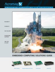
<strong>Dual</strong>/<strong>Quad</strong> <strong>Multiband</strong> <strong>Transceiver</strong> <strong>with</strong> <strong>FPGA</strong> - <strong>x16</strong> <strong>PCIe</strong><br />
General Information<br />
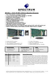
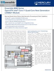
Model 7741 is a software radio transceiver<br />
suitable for connection to HF or IF<br />
ports of a communications system. It is<br />
available <strong>with</strong> either two A/D and two<br />
D/A converters (Model 7741) or four<br />
A/D and four D/A converters (Model<br />
7741D), and is capable of bandwidths to<br />
50 MHz and above. It attaches directly to<br />
motherboards <strong>with</strong> full length PCI Express<br />
(<strong>PCIe</strong>) interface slots for installation in<br />
various PCs, blade servers and computer<br />
systems.<br />
A/D Converter Stage<br />
The front end accepts two or four full<br />
scale analog HF or IF inputs on front panel<br />
MMCX connectors at +10 dBm into 50 ohms<br />
<strong>with</strong> transformer coupling for the LTC2255<br />
14-bit 125 MHz A/Ds.<br />
The digital outputs are delivered into the<br />
Virtex-II Pro <strong>FPGA</strong> for signal processing or<br />
for routing to other module resources.<br />
Digital Downconverter Stage<br />
The 7741 features one or two TI/Graychip<br />
GC4016 quad digital downconverters, each<br />
accepting either four 14-bit or three 16-bit<br />
digital inputs from the <strong>FPGA</strong>, which determines<br />
the source of GC4016 input data.<br />
These sources include the A/Ds, <strong>FPGA</strong> signal<br />
processing engines, SDRAM delay memory<br />
and data sources on the PCI bus.<br />
Each GC4016 channel may be set for independent<br />
tuning frequency and bandwidth.<br />
For an A/D sample clock frequency of<br />
100 MHz, the output bandwidth for each<br />
channel ranges from 5 kHz up to 2.5 MHz. By<br />
combining channels, output bandwidth of up<br />
to 5 or 10 MHz can be achieved.<br />
Digital Upconverter Stage<br />
A TI DAC5686 digital upconverter and<br />
dual D/A is attached to each <strong>FPGA</strong>, accepting<br />
baseband real or complex data streams<br />
<strong>with</strong> signal bandwidths up to 40 MHz.<br />
When operating as an upconverter, it<br />
interpolates and translates real or complex<br />
baseband input signals to any IF center<br />
frequency between DC and 160 MHz. It<br />
delivers real or quadrature (I+Q) analog<br />
outputs through two 320 MHz 16-bit D/A<br />
converters to two front panel MMCX connectors<br />
at +4 dBm into 50 ohms.<br />
If translation is disabled, the DAC5686<br />
acts as a two-channel interpolating 16-bit D/A<br />
<strong>with</strong> output sampling rates up to 500 MHz.<br />
Virtex-II Pro <strong>FPGA</strong>s<br />
One or two Xilinx XC2VP50 Virtex-II Pro<br />
<strong>FPGA</strong>s serve as control and status engines<br />
<strong>with</strong> data and programming interfaces to<br />
each of the on-board resources including the<br />
A/D converters, digital downconverter,<br />
digital upconverter and D/A converters.<br />
Factory installed <strong>FPGA</strong> functions include<br />
data multiplexing, channel selection, data<br />
packing, gating, triggering and SDRAM<br />
memory control. Option -104 adds up to 64<br />
pairs of LVDS connections to eachVirtex-II<br />
Pro <strong>FPGA</strong> for custom I/O. Option -5xx<br />
adds up to four full duplex 4X gigabit serial<br />
paths on high-speed connectors, supporting<br />
<strong>PCIe</strong> or other gigabit protocols. ➤<br />
LVDS<br />
Clock A<br />
LVDS<br />
Sync A<br />
LVDS<br />
Gate A<br />
TTL Gate/<br />
Trigger<br />
TTL Sync<br />
LVDS<br />
Gate B<br />
LVDS<br />
Sync B<br />
LVDS<br />
Clock B<br />
Sample<br />
Clock A In<br />
Sample<br />
Clock B In<br />
TIMING BUS<br />
GENERATOR A<br />
TIMING BUS<br />
GENERATOR B<br />
SYNC<br />
INTERRUPTS<br />
& CONTROL<br />
XTL<br />
OSC. A<br />
Clock/Sync/<br />
Gate<br />
Bus A<br />
Bus B<br />
XTL<br />
OSC. B<br />
Control/<br />
Status<br />
To All<br />
Sections<br />
64<br />
125 MHz<br />
14-BIT A/D<br />
GPIO 1<br />
(68-Pin)<br />
14<br />
RF In<br />
RF XFORMR<br />
125 MHz<br />
14-BIT A/D<br />
14<br />
16<br />
16<br />
16<br />
14<br />
GC4016<br />
4-CHANNEL<br />
DDC<br />
XC2VP50 VIRTEX-II PRO <strong>FPGA</strong><br />
DSP - DDC - DUC - Digital Delay - Demodulation - Decoding - Control<br />
4X<br />
Gbit<br />
Serial<br />
RF In<br />
RF XFORMR<br />
DDR<br />
SDRAM<br />
128 MB<br />
4X<br />
Gbit<br />
Serial<br />
32 32 32<br />
DDR<br />
SDRAM<br />
128 MB<br />
4X<br />
4X<br />
DDR<br />
SDRAM<br />
256 MB<br />
RF Out<br />
RF XFORMR<br />
RF 16-BIT XFORMR D/A<br />
PCI BUS 1<br />
(64 Bits / 66 MHz)<br />
24<br />
32<br />
64<br />
FLASH<br />
16 MB<br />
PCI 2.2 INTERFACE<br />
(64 bits/66 MHz)<br />
PCI TO <strong>PCIe</strong><br />
BRIDGE<br />
RF Out<br />
RF XFORMR<br />
16-BIT D/A<br />
DAC5686<br />
DIGITAL UPCONVERTER<br />
4X<br />
32<br />
RF XFORMR<br />
RF 16-BIT XFORMR D/A<br />
FLASH<br />
16 MB<br />
32<br />
PCI EXPRESS SWITCH<br />
PEX 8548<br />
RF Out<br />
32<br />
PCI BUS 2<br />
(64 Bits / 66 MHz)<br />
PCI TO <strong>PCIe</strong><br />
BRIDGE<br />
GC4016<br />
4-CHANNEL<br />
DDC<br />
24<br />
16<br />
16<br />
16<br />
14<br />
125 MHz<br />
14-BIT A/D<br />
XC2VP50 VIRTEX-II PRO <strong>FPGA</strong><br />
DSP - DDC - DUC - Digital Delay - Demodulation - Decoding - Control<br />
64<br />
PCI 2.2 INTERFACE<br />
(64 bits/66 MHz)<br />
RF XFORMR<br />
16-BIT D/A<br />
DAC5686<br />
DIGITAL UPCONVERTER<br />
4X<br />
32<br />
DDR<br />
SDRAM<br />
256 MB<br />
RF Out<br />
32<br />
DDR<br />
SDRAM<br />
128 MB<br />
4X<br />
4X<br />
32<br />
DDR<br />
SDRAM<br />
128 MB<br />
14<br />
RF In<br />
RF XFORMR<br />
4X<br />
Gbit<br />
Serial<br />
125 MHz<br />
14-BIT A/D<br />
14<br />
RF In<br />
RF XFORMR<br />
4X<br />
Gbit<br />
Serial<br />
64<br />
GPIO 2<br />
(68-Pin)<br />
XTL<br />
OSC. C<br />
Clock/Sync/<br />
Gate<br />
Bus C<br />
Bus D<br />
XTL<br />
OSC. D<br />
Control/<br />
Status<br />
To All<br />
Sections<br />
SYNC<br />
INTERRUPTS<br />
& CONTROL<br />
TIMING BUS<br />
GENERATOR C<br />
TIMING BUS<br />
GENERATOR D<br />
Sample<br />
Clock C In<br />
Sample<br />
Clock D In<br />
LVDS<br />
Clock C<br />
LVDS<br />
Sync C<br />
LVDS<br />
Gate C<br />
TTL Gate/<br />
Trigger<br />
TTL Sync<br />
LVDS<br />
Gate D<br />
LVDS<br />
Sync D<br />
LVDS<br />
Clock D<br />
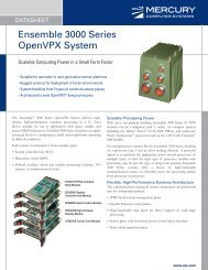
Model 7741D<br />
SER<br />
I/O A<br />
SER<br />
I/O B<br />
16X<br />
PCI Express (16X)<br />
SER<br />
I/O C<br />
SER<br />
I/O D<br />
Pentek, Inc.<br />
One Park Way ◆ Upper Saddle River ◆ New Jersey 07458<br />
Tel: 201 . 818 . 5900 ◆ Fax: 201 . 818 . 5904 ◆ Email: info@pentek.com<br />
www.pentek.com<br />
1
Models 7741, 7741D<br />
<strong>Dual</strong>/<strong>Quad</strong> <strong>Multiband</strong> <strong>Transceiver</strong> <strong>with</strong> <strong>FPGA</strong> - <strong>x16</strong> <strong>PCIe</strong><br />
Ordering Information<br />
Model Description<br />
7741 <strong>Dual</strong> <strong>Multiband</strong><br />
<strong>Transceiver</strong> <strong>with</strong> <strong>FPGA</strong> -<br />
Full-length <strong>x16</strong> <strong>PCIe</strong><br />
7741D <strong>Quad</strong> <strong>Multiband</strong><br />
<strong>Transceiver</strong> <strong>with</strong> <strong>FPGA</strong> -<br />
Full-length <strong>x16</strong> <strong>PCIe</strong><br />
Options:<br />
-002 Full-scale output: –2 dBm<br />
into 50 ohms;<br />
3 dB passband: 400 kHz<br />
to 800 MHz<br />
-050 XC2VP50 Virtex-II Pro<br />
<strong>FPGA</strong> (one for Model<br />
7741, two for 7741D)<br />
-100 All oscillators 100 MHz<br />
-101 TI DAC5687 replaces the<br />
TI DAC5686<br />
-104 <strong>FPGA</strong> I/O through GPIO<br />
connector(s)<br />
-125 125 MHz Bus A/C and<br />
100 MHz Bus B/D<br />
internal oscillators<br />
-420 <strong>Dual</strong> wideband DDC and<br />
digital interpolation filter<br />
cores, factory-installed in<br />
one <strong>FPGA</strong> (Model 7741)<br />
or two <strong>FPGA</strong>s (7741D)<br />
-430 256-channel narrowband<br />
DDC core, factory-installed<br />
in one <strong>FPGA</strong> (Model<br />
7741) or two <strong>FPGA</strong>s<br />
(7741D)<br />
-5xx Gigabit Serial I/O - two<br />
full duplex 4X paths<br />
(Model 7741) or four full<br />
duplex 4X paths (7741D)<br />
➤ Clocking and Synchronization<br />
Two independent internal timing buses<br />
per <strong>FPGA</strong> can provide either a single clock<br />
or two different clock rates for the corresponding<br />
input and output signals.<br />
Each timing bus includes a clock, sync,<br />
and gate or trigger signal. Signals from<br />
either Timing Bus can be selected as the timing<br />
source for the associated A/Ds, downconverter,<br />
upconverter and D/As. Two<br />
external reference clocks or two internal<br />
clocks may be used for each timing bus.<br />
One or two front panel 26-pin LVDS<br />
Clock/Sync connectors allow multiple<br />
modules to be synchronized. In the slave<br />
mode, each accepts differential LVDS<br />
inputs that drive the clock, sync and gate<br />
signals for the two internal timing buses.<br />
In the master mode, the LVDS bus can<br />
drive one or both sets of timing signals<br />
from the two internal timing buses for<br />
synchronizing multiple modules.<br />
Up to seven slave 7741’s can be driven<br />
from each LVDS bus master, supporting<br />
synchronous sampling and sync functions<br />
across all connected boards.<br />
Memory Resources<br />
Three independent banks of SDRAM<br />
are available to each <strong>FPGA</strong> (to 1 GB max.).<br />
Built-in memory functions include an A/D<br />
data transient capture mode <strong>with</strong> pre- and<br />
post-triggering; a D/A waveform generator<br />
mode; and an A/D data delay mode for applications<br />
such as tracking receivers.<br />
The SDRAMs are also available as a resource<br />
for the two PowerPC processor cores<br />
<strong>with</strong>in each <strong>FPGA</strong>. A 16 MB FLASH<br />
memory supports booting and program<br />
store for these processors.<br />
PCI Express Interface<br />
The 7741 includes a multiple port,<br />
48-lane Gen 2 <strong>PCIe</strong> switch <strong>with</strong> integrated<br />
SerDes. The switch provides <strong>x16</strong> wide<br />
connection to the <strong>PCIe</strong> interface, allowing<br />
high-speed data transfers to and from the<br />
motherboard. Switch ports each include<br />
buffer memory to minimize bottlenecks,<br />
<strong>with</strong> two 4X <strong>PCIe</strong> connections provided<br />
to each <strong>FPGA</strong>, as well as one 4X connection<br />
to each 64-bit PCI interface.<br />
Specifications<br />
Analog Signal Inputs<br />
Input Type: Transformer-coupled, front<br />
panel female MMCX connectors<br />
Transformer Type: Coil Craft<br />
WBC1-1TLB<br />
Full Scale Input: +10 dBm into 50 ohms<br />
3 dB Passband: 250 kHz to 300 MHz<br />
A/D Converters<br />
Type: Linear Technology LTC2255<br />
Sampling Rate: 1 MHz to 125 MHz<br />
Internal Clock: Crystal osc. (2 per A/D)<br />
External Clock: 1 to 125 MHz<br />
Resolution: 14 bits<br />
Digital Downconverter<br />
Type: TI/Graychip GC4016<br />
Decimation: 32 to 16,384; <strong>with</strong> channel<br />
combining mode: 8 or 16<br />
Data Source: A/D, <strong>FPGA</strong>, or PCI interface<br />
Control Source: <strong>FPGA</strong> or PCI interface<br />
Output: Parallel complex data<br />
Receiver Bypass Mode: Data from the A/Ds<br />
can be written directly into the <strong>FPGA</strong>s at<br />
a rate equal to the A/D clock decimated<br />
by any integer between 1 and 4096<br />
Front Panel Analog Signal Outputs<br />
Output Type: Transformer-coupled,<br />
front panel female MMCX connectors<br />
Full Scale Output: +4 dBm into 50 ohms<br />
Option -002: –2 dBm into 50 ohms<br />
3 dB Passband: 60 kHz to 300 MHz<br />
Option -002: 400 kHz to 800 MHz<br />
Digital Upconverter<br />
Type: TI DAC5686<br />
Input Bandwidth: 40 MHz, max.<br />
Output IF: DC to 160 MHz<br />
Output Signal: Analog, real or quadrature<br />
Sampling Rate: 320 MHz, max; 500 MHz<br />
max. <strong>with</strong> upconversion disabled<br />
Resolution: 16 bits<br />
Clock Sources: Selectable from onboard<br />
crystal oscillators, external or LVDS clocks<br />
External Clocks<br />
Type: Female MMCX connector, sine<br />
wave, 0 to +10 dBm, AC- coupled, 50 ohm<br />
Sync/Gate Bus: 26-pin connector, dual<br />
clock/sync/gate input/output LVDS<br />
buses; one sync/gate input TTL signal<br />
Field Programmable Gate Array<br />
Type: Xilinx Virtex-II Pro<br />
Option -050: XC2VP50<br />
Option -104: 64 lines per <strong>FPGA</strong><br />
Memory<br />
DDR SDRAM: 512 MB in three banks<br />
per <strong>FPGA</strong> (maximum 1 GB)<br />
FLASH: One bank of 16 MB per <strong>FPGA</strong><br />
(maximum 32 MB)<br />
PCI to <strong>PCIe</strong> Interface<br />
PCI Bus: 64-bit, 66 MHz<br />
DMA: 9 channel demand-mode and<br />
chaining controller per PCI bus<br />
<strong>PCIe</strong> Interface: Gen. 2, <strong>x16</strong> width<br />
<strong>PCIe</strong> Ports: two 4X ports per <strong>FPGA</strong><br />
one 4X port per PCI bus<br />
one 16X port to <strong>PCIe</strong> motherboard<br />
Environmental (Commercial version)<br />
Operating Temp: 0° to 50° C<br />
Storage Temp: –20° to 90° C<br />
Relative Humidity: 0 to 95%, non-cond.<br />
Size: Full-length <strong>PCIe</strong>, 4.38 in. x 12.3 in.<br />
Pentek, Inc. One Park Way ◆ Upper Saddle River ◆ New Jersey 07458<br />
2 www.pentek.com<br />
Tel: 201 . 818 . 5900 ◆ Fax: 201 . 818 . 5904 ◆ Email: info@pentek.com
Models 7741, 7741D<br />
<strong>Dual</strong>/<strong>Quad</strong> <strong>Multiband</strong> <strong>Transceiver</strong> <strong>with</strong> <strong>FPGA</strong> - <strong>x16</strong> <strong>PCIe</strong><br />
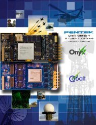
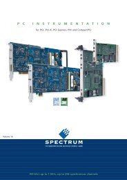
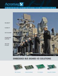
A/D Performance<br />
Spurious Free Dynamic Range<br />
Spurious Pick-up<br />
f in<br />
= 70 MHz, f s<br />
= 100 MHz<br />
f s<br />
= 100 MHz, 32k point FFT, 8 averages<br />
Input Frequency Response<br />
Two-Tone SFDR<br />
f s<br />
= 100 MHz<br />
f 1<br />
= 29.5 MHz, f 2<br />
= 30.5 MHz, f s<br />
= 100 MHz<br />
Crosstalk<br />
Phase Noise<br />
f in Ch2<br />
= 69 MHz, f s<br />
= 100 MHz, Ch 1 shown<br />
f in<br />
= 69 MHz, f s<br />
= 100 MHz<br />
Phase Noise @ 100 kHz = -102 - 10*log(610) = -129.8 dB/Hz<br />
Pentek, Inc.<br />
One Park Way ◆ Upper Saddle River ◆ New Jersey 07458<br />
Tel: 201 . 818 . 5900 ◆ Fax: 201 . 818 . 5904 ◆ Email: info@pentek.com<br />
www.pentek.com<br />
3
Models 7741, 7741D<br />
<strong>Dual</strong>/<strong>Quad</strong> <strong>Multiband</strong> <strong>Transceiver</strong> <strong>with</strong> <strong>FPGA</strong> - <strong>x16</strong> <strong>PCIe</strong><br />
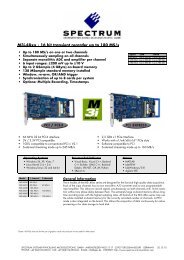
D/A Performance<br />
Two-Tone Intermodulation Distortion<br />
f 1<br />
= 69.5 MHz, f 2<br />
= 70.5 MHz, f s<br />
= 100 MHz<br />
Pentek, Inc. One Park Way ◆ Upper Saddle River ◆ New Jersey 07458<br />
4 www.pentek.com<br />
Tel: 201 . 818 . 5900 ◆ Fax: 201 . 818 . 5904 ◆ Email: info@pentek.com