Download Spectrum Catalogue 2010(10MB)
Download Spectrum Catalogue 2010(10MB)
Download Spectrum Catalogue 2010(10MB)

Create successful ePaper yourself
Turn your PDF publications into a flip-book with our unique Google optimized e-Paper software.
P C I N S T R U M E N T A T I O N<br />
for PCI, PCI-X, PCI Express, PXI and CompactPCI<br />
Volume 16<br />
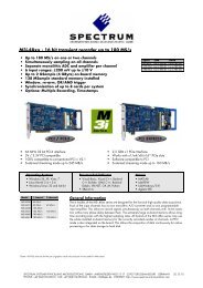
100 kS/s up to 1 GS/s, up to 256 synchronous channels
Preface by the Managing Director<br />
Judging when a technical solution works well can only be known when the results can be read in precise data.<br />
This idea and its practical application is the subject of our ambition.<br />
Precision needs on one hand accurately fitting technology, whilst on the other precise communication. Therefore<br />
the sixteenth volume of our catalog is produced in its new format for the second time – with coloured<br />
structuring for the benefit of higher clarity, providing an overview of soft and hardware possibilities combined<br />
with comprehensive technical details, as well as easy handling – just like the usability of the products.<br />
What is our aim? Not only to have satisfied and well informed readers, but also provide the basis of research<br />
in finding the best optimised solutions for you.<br />
Finding the best solution is not just about technology. First of all it´s all about communication! We want to<br />
stimulate communication between <strong>Spectrum</strong> and its business partners. It´s our customers demands that stimulates<br />
our ambition to find the best solution to your requirements! Take our product-offers as an invitation to ask for more, it is you who help us to keep<br />
standards up and improve. So once more: Any requests, suggestions and comments are welcome!<br />
Gisela Hassler<br />
Managing Director<br />
Preface by the Technical Director<br />
In <strong>2010</strong> the <strong>Spectrum</strong> M3i product line (14 bit 400 MS/s, 12 bit 500 MS/s and 8 bit<br />
1 GS/s) got into full production. All M3i products can now be ordered with SMA<br />
connection to enhance the high frequency signal quality even more and to simplify<br />
the interconnection between high frequency components. November <strong>2010</strong> the fourth<br />
M3i series was released, a high speed high resolution 16 bit digitizer with up to 180<br />
MS/s of sampling speed.<br />
As all <strong>Spectrum</strong> cards of the last years each version of the M3i.48xx series is available<br />
as PCI/PCI-X version as well as PCI Express version for the same price. We advise<br />
customers to check carefully their use of PCI cards as the PC market has discontin ued<br />
PCI slots and already standard systems with PCI slots are becoming rare. Don’t bind<br />
your future to a manufacturer that can only deliver PCI components!<br />
1<br />
The measurement software SBench 6 is now supporting all <strong>Spectrum</strong> products that<br />
have been released in the last 10 years. SBench 6 allows to acquire and replay analog and digital data from memory and from hard disks. The software<br />
has proven its unique design showing sustained throughput of several hundred MB/s from and to hard disk.<br />
Our software development team is permanently improving SBench 6 and a new version with new features and improvements is released monthly.<br />
Li censed users have access to this new version without any upgrade fees. Simply download and install the new release to have access to all features.<br />
A full running demo version is available – please feel free to test the software with your hardware or even with simulated hardware to get to know the<br />
new powerful and easy-to-use features.<br />
Oliver Rovini<br />
Technical Director<br />
Editor<br />
<strong>Spectrum</strong> Systementwicklung<br />
Microelectronic GmbH<br />
Ahrensfelder Weg 13-17,<br />
22927 Grosshansdorf / Germany<br />
Phone: +49 (0)4102-6956-0<br />
Fax: +49 (0)4102-6956-66<br />
E-Mail: info@spec.de<br />
www.spectrum-instrumentation.com<br />
Trademarks / registered trademarks<br />
Microsoft, Visual Basic, Visual C++, Visual C#, Visual J#, Visual<br />
Studio, Windows, Windows 98, Windows NT, Windows 2000,<br />
Windows XP, Windows Vista and Windows 7 are trademarks or<br />
registered trademarks of Microsoft Corporation.<br />
LabVIEW, LabWindows/CVI, DASYLab and DIAdem are trademarks or<br />
registered trademarks of National Instruments Corporation.<br />
Delphi and C++Builder are trademarks or registered trademarks of<br />
Embarcadero Technologies, Inc.<br />
MATLAB is a trademark or registered trademark of The MathWorks, Inc.<br />
Agilent VEE, VEE Pro and VEE OneLab are trademarks or registered<br />
trademarks of Agilent Technologies, Inc.<br />
PCI-SIG, PCI, PCI-X and the PCI EXPRESS/PCIe design mark are<br />
registered trademarks and/or service marks of PCI-SIG.<br />
SBench is a registered trademark of <strong>Spectrum</strong> Systementwicklung<br />
Microelectronic GmbH.<br />
Changes and copyright<br />
Adaptations and changes to the<br />
products that are necessary for the<br />
technical development are possible.<br />
We take no liability for faulty<br />
values or printing errors.<br />
Copyright © <strong>2010</strong> by <strong>Spectrum</strong><br />
Systementwicklung Microelectronic GmbH.<br />
Reprinting and copying is only allowed<br />
with a written permission.<br />
All rights reserved.
Table of Contents<br />
SB6<br />
Preface . . . . . . . . . . . . . . . . . . . . . . . . . . . . . . . . . . . . . . . . . . . . . . . . . . . . . . . . . . . . . . . . . . . . . . . . . . . . .Page 1<br />
Imprint . . . . . . . . . . . . . . . . . . . . . . . . . . . . . . . . . . . . . . . . . . . . . . . . . . . . . . . . . . . . . . . . . . . . . . . . . . . . .Page 1<br />
Your benefits – Good Service! . . . . . . . . . . . . . . . . . . . . . . . . . . . . . . . . . . . . . . . . . . . . . . . . . . . . . . . . . . . .Page 4<br />
Company history . . . . . . . . . . . . . . . . . . . . . . . . . . . . . . . . . . . . . . . . . . . . . . . . . . . . . . . . . . . . . . . . . . . . . .Page 4<br />
Introduction . . . . . . . . . . . . . . . . . . . . . . . . . . . . . . . . . . . . . . . . . . . . . . . . . . . . . . . . . . . . . . . . . . . . . . . . .Page 5<br />
Software support<br />
Operating system drivers . . . . . . . . . . . . . . . . . . . . . . . . . . . . . . . . . . . . . . . . . . . . . . . . . . . . . . . . . .Page 6<br />
Linux support . . . . . . . . . . . . . . . . . . . . . . . . . . . . . . . . . . . . . . . . . . . . . . . . . . . . . . . . . . . . . . . . . .Page 7<br />
<strong>Spectrum</strong> Control Center and Demo Mode . . . . . . . . . . . . . . . . . . . . . . . . . . . . . . . . . . . . . . . . . . . .Page 7<br />
SBench 6 . . . . . . . . . . . . . . . . . . . . . . . . . . . . . . . . . . . . . . . . . . . . . . . . . . . . . . . . . . . . . . . . . . . . . .Page 8<br />
LabVIEW . . . . . . . . . . . . . . . . . . . . . . . . . . . . . . . . . . . . . . . . . . . . . . . . . . . . . . . . . . . . . . . . . . . . . .Page 12<br />
MATLAB . . . . . . . . . . . . . . . . . . . . . . . . . . . . . . . . . . . . . . . . . . . . . . . . . . . . . . . . . . . . . . . . . . . . . .Page 13<br />
VEE / LabWindows/CVI . . . . . . . . . . . . . . . . . . . . . . . . . . . . . . . . . . . . . . . . . . . . . . . . . . . . . . . . . . .Page 13<br />
2<br />
PCI / PCI-X / PCI Express based cards<br />
Bus systems and product overview . . . . . . . . . . . . . . . . . . . . . . . . . . . . . . . . . . . . . . . . . . . . . . . . . .Page 14<br />
M2i/M3i – new generation of instruments . . . . . . . . . . . . . . . . . . . . . . . . . . . . . . . . . . . . . . . . . . . .Page 16<br />
Transient capture or streaming? . . . . . . . . . . . . . . . . . . . . . . . . . . . . . . . . . . . . . . . . . . . . . . . . . . . .Page 18<br />
Options / features of M2i and M3i series<br />
Trigger, additional I/O . . . . . . . . . . . . . . . . . . . . . . . . . . . . . . . . . . . . . . . . . . . . . . . . . . . . . . .Page 20<br />
Clock, operation modes . . . . . . . . . . . . . . . . . . . . . . . . . . . . . . . . . . . . . . . . . . . . . . . . . . . . .Page 21<br />
Synchronization . . . . . . . . . . . . . . . . . . . . . . . . . . . . . . . . . . . . . . . . . . . . . . . . . . . . . . . . . . .Page 22<br />
Digitizers / DAQ cards<br />
Introduction to <strong>Spectrum</strong> digitizers . . . . . . . . . . . . . . . . . . . . . . . . . . . . . . . . . . . . . . . . . . . . .Page 24<br />
Extended trigger modes . . . . . . . . . . . . . . . . . . . . . . . . . . . . . . . . . . . . . . . . . . . . . . . . . . . . .Page 25<br />
Input signal conditioning . . . . . . . . . . . . . . . . . . . . . . . . . . . . . . . . . . . . . . . . . . . . . . . . . . . .Page 26<br />
Products<br />
M3i.21xx – 8 bit high-speed digitizer up to 1 GS/s . . . . . . . . . . . . . . . . . . . . . . . . . . . . . . . . .Page 28<br />
M2i.20xx – 8 bit multi-purpose digitizer up to 200 MS/s . . . . . . . . . . . . . . . . . . . . . . . . . . . .Page 30<br />
M3i.32xx – 12 bit fastest digitizers up to 500 MS/s . . . . . . . . . . . . . . . . . . . . . . . . . . . . . . . .Page 32<br />
M2i.30xx – 12 bit multi-purpose digitizer up to 200 MS/s . . . . . . . . . . . . . . . . . . . . . . . . . . .Page 34<br />
M2i.31xx – 12 bit multi-channel data acquisition up to 25 MS/s . . . . . . . . . . . . . . . . . . . . . .Page 36<br />
M3i.41xx – 14 bit digitizer up to 400 MS/s . . . . . . . . . . . . . . . . . . . . . . . . . . . . . . . . . . . . . .Page 38<br />
M2i.40xx – 14 bit multi-purpose 14 bit DAQ up to 50 MS/s . . . . . . . . . . . . . . . . . . . . . . . . . .Page 40<br />
M3i.48xx – 16 bit high-precision digitizer up to 180 MS/s . . . . . . . . . . . . . . . . . . . . . . . . . . .Page 42<br />
M2i.46xx – 16 bit high-precision digitizer up to 3 MS/s . . . . . . . . . . . . . . . . . . . . . . . . . . . . .Page 44<br />
M2i.47xx – 16 bit, 16 channel synchronous data acquisition up to 1.33 MS/s . . . . . . . . . . . .Page 46<br />
Arbitrary Waveform Generators / D/A cards<br />
Introduction to <strong>Spectrum</strong> D/A cards, operation modes . . . . . . . . . . . . . . . . . . . . . . . . . . . . . .Page 48<br />
Output signal conditioning . . . . . . . . . . . . . . . . . . . . . . . . . . . . . . . . . . . . . . . . . . . . . . . . . . .Page 49<br />
Products<br />
M2i.61xx – 8 bit high-speed generator cards . . . . . . . . . . . . . . . . . . . . . . . . . . . . . . . . . . . . .Page 50<br />
M2i.60xx – 14 bit high-speed, high-precision AWG cards . . . . . . . . . . . . . . . . . . . . . . . . . . . .Page 50<br />
www.spectrum-instrumentation.com – extensive homepage service<br />
Our web page informs you 24 hours the day about hardware, software,<br />
options and new products. You have a full-text search engine<br />
as well as a parametric search.
Digital I/O cards and pattern generators<br />
Introduction to <strong>Spectrum</strong> DIO cards . . . . . . . . . . . . . . . . . . . . . . . . . . . . . . . . . . . . . . . . . . . .Page 52<br />
Operation modes . . . . . . . . . . . . . . . . . . . . . . . . . . . . . . . . . . . . . . . . . . . . . . . . . . . . . . . . . .Page 53<br />
Trigger / output signal conditioning . . . . . . . . . . . . . . . . . . . . . . . . . . . . . . . . . . . . . . . . . . . .Page 53<br />
Products<br />
M2i.70xx – Fast digital I/O with TTL levels . . . . . . . . . . . . . . . . . . . . . . . . . . . . . . . . . . . . . . .Page 54<br />
M2i.72xx – Pattern generator with programmable levels . . . . . . . . . . . . . . . . . . . . . . . . . . . .Page 56<br />
CompactPCI 6U and PXI 3U cards<br />
Bus systems and product overview . . . . . . . . . . . . . . . . . . . . . . . . . . . . . . . . . . . . . . . . . . . . . . . . . .Page 58<br />
Options / features of MC and MX series<br />
Transfer modes, trigger, clock . . . . . . . . . . . . . . . . . . . . . . . . . . . . . . . . . . . . . . . . . . . . . . . . .Page 60<br />
Operation modes . . . . . . . . . . . . . . . . . . . . . . . . . . . . . . . . . . . . . . . . . . . . . . . . . . . . . . . . . .Page 61<br />
Synchronization . . . . . . . . . . . . . . . . . . . . . . . . . . . . . . . . . . . . . . . . . . . . . . . . . . . . . . . . . . .Page 62<br />
PXI features . . . . . . . . . . . . . . . . . . . . . . . . . . . . . . . . . . . . . . . . . . . . . . . . . . . . . . . . . . . . . .Page 63<br />
Digitizers / DAQ cards<br />
Introduction to <strong>Spectrum</strong> industrial digitizers . . . . . . . . . . . . . . . . . . . . . . . . . . . . . . . . . . . . .Page 64<br />
Trigger and input signal conditioning . . . . . . . . . . . . . . . . . . . . . . . . . . . . . . . . . . . . . . . . . . .Page 64<br />
Products<br />
MC.20xx / MX.20xx – 8 bit digitizer up to 200 MS/s . . . . . . . . . . . . . . . . . . . . . . . . . . . . . . .Page 66<br />
MC.30xx / MX.30xx – 12 bit digitizer up to 200 MS/s . . . . . . . . . . . . . . . . . . . . . . . . . . . . . .Page 68<br />
MC.31xx / MX.31xx – 12 bit multi-channel data acquisition up to 25 MS/s . . . . . . . . . . . . . .Page 70<br />
MC.40xx / MX.40xx – 14 bit multi-purpose 14 bit DAQ up to 50 MS/s . . . . . . . . . . . . . . . . . .Page 72<br />
MC.46xx / MX.46xx – 16 bit high-precision digitizer up to 3 MS/s . . . . . . . . . . . . . . . . . . . . .Page 74<br />
MC.47xx / MX.47xx – 16 bit, 16 channel synchronous data acquisition up to 500 kS/s . . . . .Page 76<br />
Arbitrary Waveform Generators / D/A cards<br />
Introduction to <strong>Spectrum</strong> industrial D/A cards, operation modes . . . . . . . . . . . . . . . . . . . . . .Page 78<br />
Output signal conditioning . . . . . . . . . . . . . . . . . . . . . . . . . . . . . . . . . . . . . . . . . . . . . . . . . . .Page 79<br />
Products<br />
MC.61xx / MX.61xx – 8 bit high-speed generator cards . . . . . . . . . . . . . . . . . . . . . . . . . . . . .Page 80<br />
MC.60xx / MX.60xx – 14 bit high-speed, high-precision AWG cards . . . . . . . . . . . . . . . . . . . .Page 80<br />
Digital I/O cards and pattern generators<br />
Introduction to <strong>Spectrum</strong> industrial DIO cards . . . . . . . . . . . . . . . . . . . . . . . . . . . . . . . . . . . .Page 82<br />
Operation modes . . . . . . . . . . . . . . . . . . . . . . . . . . . . . . . . . . . . . . . . . . . . . . . . . . . . . . . . . .Page 82<br />
Trigger, output signal conditioning . . . . . . . . . . . . . . . . . . . . . . . . . . . . . . . . . . . . . . . . . . . . .Page 83<br />
Products<br />
MC.70xx / MX.70xx – Fast digital I/O with TTL levels . . . . . . . . . . . . . . . . . . . . . . . . . . . . . . .Page 84<br />
MC.72xx / MX.72xx – Pattern generator with programmable levels . . . . . . . . . . . . . . . . . . . .Page 86<br />
3<br />
Complete measurement systems<br />
19” industrial systems . . . . . . . . . . . . . . . . . . . . . . . . . . . . . . . . . . . . . . . . . . . . . . . . . . . . . . . . . . . .Page 88<br />
Portable systems . . . . . . . . . . . . . . . . . . . . . . . . . . . . . . . . . . . . . . . . . . . . . . . . . . . . . . . . . . . . . . . .Page 89<br />
Docking stations for Laptop based measurements . . . . . . . . . . . . . . . . . . . . . . . . . . . . . . . . . . . . . . .Page 90<br />
Adapter cables . . . . . . . . . . . . . . . . . . . . . . . . . . . . . . . . . . . . . . . . . . . . . . . . . . . . . . . . . . . . . . . . . . . . . . . . .Page 91<br />
<strong>Spectrum</strong>’s Customers . . . . . . . . . . . . . . . . . . . . . . . . . . . . . . . . . . . . . . . . . . . . . . . . . . . . . . . . . . . . . . . . . . . .Page 92<br />
Index . . . . . . . . . . . . . . . . . . . . . . . . . . . . . . . . . . . . . . . . . . . . . . . . . . . . . . . . . . . . . . . . . . . . . . . . . . . . . . . .Page 93<br />
At the moment this information is available:<br />
Data sheets<br />
Manuals<br />
Software SBench<br />
The newest driver version (Windows/Linux)<br />
Examples for different programming languages<br />
Application notes<br />
Information about new products<br />
Information about enhanced functionality<br />
of hardware and software
Your Benefits – Good Service!<br />
We are here for you – indeed!<br />
We have always given the customer our highest priority. Handling inquiries and orders on the<br />
same day is a matter of course for us. Since the testing, configuration and commissioning always<br />
occurs on our premises with process optimisation and our design engineers are constantly devel -<br />
oping new or refined product lines, we achieve high standards of service and quality. With all of<br />
the specialised departments concentrated under one roof on the basis of competencies, we can<br />
flexibly implement our customers’ wishes. Short delivery periods and technical adaptations due<br />
to special customer specifications are examples of this.<br />
Call center? No thank you!<br />
You get free-of-charge support and technical advice directly from our local partners. For any more extensive questions and support issues, our design<br />
and production team in Grosshansdorf, Germany is ready to assist you and answer your inquiries.<br />
“Made in Germany”<br />
All of the products from <strong>Spectrum</strong> are “Made in Germany” – from design to production! – fulfilling the highest quality standards.<br />
Lifetime Updates<br />
Software updates are available free of charge for a lifetime. The current version is available for download on our homepage.<br />
2 Years of Product Warranty<br />
A shorter warranty period would be possible for business-to-business. But we trust in our product quality, so we offer a two-year warranty that begins<br />
with the delivery of our products. In order to meet customer project requirements, we also offer a warranty extension for a period of up to 5 years.<br />
Product Availability<br />
As long as requested. We still sold ISA boards that were developed in 1991 until 2008, even though we have not included them for years in our catalogue<br />
or on our homepage.<br />
History<br />
4<br />
1989<br />
Company founded with the business objective of developing custom-built instrumentation<br />
1991 Began developing own product line and created the first ISA card<br />
1993 First 200 MS/s 8 bit ISA DAQ card released<br />
1993 Office relocation from Hamburg to Schleswig-Holstein<br />
1994 High-speed 8-bit 400 MS/s ISA card developed<br />
1995 First Arbitrary Waveform Generator card released<br />
1996 Prototype card of the new bus standard PCI is completed<br />
1997 First PCI DAQ card was created<br />
1998 First 12 bit DAQ card with 80 MS/s<br />
1999 First digital I/O card – still sold to OEM customers<br />
2000 Fastest 8 bit digitizer with 500 MS/s and 512 MByte of memory
Introduction<br />
Application Areas<br />
A PC instrumentation board, be it PCI, PCI-X, PCI Express, PXI or CompactPCI, transforms a<br />
standard PC to a universal powerful instrument. Compared to a stand-alone solution there are<br />
several advantages:<br />
Best flexibility<br />
Data is rapidly available for calculation<br />
A wide range of available software solutions<br />
Software programmable hardware settings for ease of use and highest performance<br />
Easy combination of different hardware possible<br />
Scalable memory size<br />
Excellent price-performance ratio<br />
Processing power is not limited by the instrument but can simply be increased by<br />
updating the host PC<br />
Setting up a mixed mode system or stimulus-response test benches is no problem combining<br />
the wide range of multi channel A/D, D/A and Digital I/O cards with the internal card synchronisation.<br />
In contrast to stand-alone instruments which only have one fixed function, the modular<br />
instruments from <strong>Spectrum</strong> can turn into any kind of virtual instrument using the latest PC<br />
processing technology.<br />
<strong>Spectrum</strong> has focused its business on the high-speed A/D, D/A and Digital I/O range with sampling<br />
rates between 100 kS/s and 1 GS/s. Fast amplifiers and high-quality converters allow the<br />
acquisition and replay of high-frequency signals. As a result of the substantial on-board<br />
memory even fast signals may be recorded over a long time period with a high precision. The<br />
modular product line first introduced in 2001 has a host of advantages compared to earlier<br />
product lines:<br />
Wide range of products available for different bus systems<br />
Universal, easy-to-program driver<br />
On-board memory standardised at 256 MBytes (16 MBytes for MC and MX)<br />
Standard on-board memory expandable to 4 GBytes (depending on card family)<br />
Continuous data transfer up to 245 MBytes/s in PCI-X/PCI-66 slots<br />
Continuous data transfer up to 125 MBytes/s in PCI slots<br />
Thousands of installations world-wide stand for best quality and reliable products<br />
The cards are also available in a completely installed system. We offer a wide range of standard<br />
systems, 19“ industrial systems or mobile PCs. For the mobile use together with a notebook,<br />
a range of high-performance docking stations that can hold up to three PCI boards is<br />
also available.<br />
Sonar<br />
Radar<br />
Laser<br />
Acoustics<br />
Ultrasound<br />
LDA/PDA<br />
Medical equipment<br />
Automation<br />
Production tests<br />
Chip test<br />
Research and development<br />
Automotive<br />
Laboratory equipment<br />
Spectroscopy<br />
Quality control<br />
Long-time data streaming<br />
Instrument development<br />
Prototype development<br />
ATE<br />
and many more<br />
5<br />
2001 Launch of MI series, the first modular PCI cards<br />
2002 12 bit digitizer of the MI.30xx series reach 200 MS/s<br />
2003 First 14 bit fast DAQ card with sampling rate of 50 MS/s<br />
2004 MC and MX cards allow MI to go industrial<br />
2004 Expansion – move to new and bigger office building<br />
2005 More than 70 different PCI based cards available<br />
2006 Delivery of the first M2i cards – a new generation of modular instruments<br />
2007 All M2i cards available as PCI Express version<br />
2009 Launch of the first M3i card with 500 MS/s 12 bit A/D<br />
2009 SBench 6, the new measurement software, is ready<br />
<strong>2010</strong> First 1 GS/s digitizer released<br />
<strong>2010</strong> 16 bit high-speed digitizer
Software<br />
The connecting link between the user and the hardware is always the software. The wide range of software products supported by <strong>Spectrum</strong> allows the<br />
user to choose the software that he wants. There are four different ways to use the high-end PC instruments from <strong>Spectrum</strong>:<br />
Easy-to-use software SBench 6 (Windows and Linux) either as stand-alone<br />
application or in combination with further analysis software like MATLAB, FlexPro<br />
or Diadem<br />
Classical text based programming with C/C++, Visual Basic, Delphi, C#, J# or<br />
VB.NET languages<br />
Advanced text based programming with MATLAB or LabWindows/CVI<br />
Graphical programming with LabVIEW or Agilent VEE<br />
Text based Application SBench 6<br />
3rd Party Measurement SW<br />
Visual<br />
C++<br />
C++<br />
Builder<br />
Visual<br />
Basic<br />
Borland<br />
Delphi<br />
.Net based<br />
C# J# VB.NET<br />
Other<br />
Compiler<br />
Gnu<br />
C/C++<br />
LabVIEW<br />
Driver<br />
MATLAB<br />
Driver<br />
VEE<br />
Driver<br />
LabWindows<br />
CVI<br />
Windows 32 Bit<br />
Kernel Driver<br />
Common Library (DLL) with a common interface on all supported platforms<br />
Windows 64 Bit<br />
Kernel Driver<br />
Linux<br />
Kernel Driver<br />
Windows 32 Bit Windows 64 Bit (PCI Express and PCI only) Linux 32/64 Bit<br />
6<br />
Operating System Drivers The standard driver is available for different operating systems and is programmed every -<br />
where in the same way. This allows an easy change from one operating system to another<br />
without major changes in the source code.<br />
This standard driver is included in the card delivery and it is possible to get the newest driver<br />
version free of charge from our homepage at any time. There are no additional SDK fees for<br />
the classical text-based programming. All boards are delivered with drivers for Windows<br />
2000, Windows XP, Windows Vista and Windows 7 as well as drivers for a huge variety of<br />
Linux systems.<br />
The driver has an unique interface for all boards within one series allowing an easy switch<br />
from one card type to another without big changes in the software. The different functionality<br />
of the boards is realised with the help of board specific software registers.<br />
Programming examples for Microsoft Visual C++, Borland C++ Builder, Gnu C++ (CygWin),<br />
Borland Delphi, Microsoft Visual Basic, C#, J#, VB.Net, Python and LabWindows/CVI are<br />
delivered with the driver. Due to the simple interface of the driver, the integration in other<br />
pro gramm ing languages or special measurement software is an easy task.<br />
The number of examples is continuously increasing giving more detailed programming<br />
examp les that allow an easy start with the <strong>Spectrum</strong> cards.<br />
64 Bit Systems<br />
Todays data acquisition cards offer up to 4 GByte of on-board memory. Handling such a lot of data<br />
on a 32 bit operating system which normally has a maximum of 2 GB of free available memory,<br />
limits the usage in all directions. <strong>Spectrum</strong> therefore offers full 64 bit support for Windows and<br />
Linux for M2i and M3i series (PCI and PCI Express) and full Linux 64 bit support for all card series.<br />
All drivers and libraries are available as 64 bit versions opening the huge 64 bit address range for<br />
data acquisition and streaming applications.<br />
When using Windows 64 bit it is still possible to run 32 bit applications using the so-called WOW64<br />
(Windows on Windows 64 Bit) extension, a Windows operating system component. As shown in the<br />
drawing any application whether 32 bit or 64 bit can access the hardware using a dedicated library<br />
that accesses the low level 64 bit kernel driver.<br />
32 Bit Application 64 Bit Application<br />
32 Bit Driver DLL 64 Bit Driver DLL<br />
64 Bit Kernel Driver<br />
Hardware
Linux Support<br />
Full Linux support included with no extra costs<br />
More than 50 different pre-compiled kernel driver modules<br />
Support of latest Suse, Fedora and Debian versions<br />
Kernel driver sources available against NDA<br />
Linux control center for card maintenance and updates<br />
SBench 6 Linux version – powerful data acquisition software<br />
In many areas Linux has itself proven as a high-quality alternative to Windows. Also the instrumentation market uses more and more Linux-based<br />
systems. <strong>Spectrum</strong> delivers loadable Linux modules for the common Linux distributions with all products for years now. But also less common Linux versions<br />
are supported. For this the source code of the driver module and the required makefiles are available from <strong>Spectrum</strong>. The user can then compile a<br />
perfectly matching version for his Linux installation.<br />
Linux driver delivery contains driver modules for more than 50 different Linux distribution versions over a number of years, including the latest version<br />
of openSUSE, Fedora and Debian, each as 32 bit and 64 bit kernel module.<br />
Besides the Linux drivers <strong>Spectrum</strong> is giving full Linux support for all current cards. The Linux version of the <strong>Spectrum</strong> control center allows all card maintenance<br />
including firmware updates, calibration and test programs. Using the Linux versions of SBench 6 provides a fully functional data acquisition and<br />
streaming application under Linux. Both programs are made from the same source code as the Windows version giving Linux users full features and func -<br />
tions on the same level as Windows users. There’s no development or porting delay between versions.<br />
Control Center and Demo Mode<br />
A special card control center is available for the<br />
<strong>Spectrum</strong> M2i/M3i driver as a stand-alone application<br />
and add-on for the drivers. This powerful<br />
tool is delivered with the cards and available<br />
under Windows and Linux and groups together<br />
all hardware main tenance functions:<br />
7<br />
Hardware information: Through the control center you can<br />
easily get the main information about all the installed <strong>Spectrum</strong><br />
hardware: Basic information as the type of card, the production<br />
date and its serial number as well as the installed memory, the<br />
hardware revisions or the installed firmware.<br />
Installation of demo cards: With the help of the card control<br />
center one can install demo cards in the system. A demo card is simulated by the<br />
<strong>Spectrum</strong> driver including data generation for acquisition cards. As the demo card is<br />
simulated on the lowest driver level all software can be tested including SBench, own<br />
applications and drivers for third-party products like LabVIEW.<br />
Debug logging: The setup of the card, driver and firmware version, all command<br />
sequences and other information can be logged to an ASCII file and can then be used<br />
for support cases.<br />
Features and Software license: SBench 6 software licenses as well as all optional<br />
features of the M2i/M3i cards, that do not require any hardware modifications, can<br />
be installed on fielded cards. The customer will get a personalised upgrade code for<br />
installation.<br />
Firmware upgrade: All M2i and M3i cards can have a later firmware upgrade to install<br />
new functions and to fix bugs. Firmware upgrade runs under Windows and Linux.<br />
Calibration: The card control center also provides an easy way to access the automatic<br />
card calibration routines of the <strong>Spectrum</strong> A/D converter cards. Depending on the used<br />
card family this can affect offset calibration only or also might include gain calibration.<br />
Memory test: The complete on-board memory of the <strong>Spectrum</strong> M2i/M3i cards is<br />
test ed with randomised data for proper functionality. Any read or write errors are<br />
documented.<br />
Transfer speed test: Measures the bus transfer speed of an installed <strong>Spectrum</strong> card<br />
in the specific system. This gives you a performance index of the system and shows<br />
which sustained data rates can be reached.<br />
Continuous memory: Setup of the desired continuous memory buffer for the next<br />
system start.<br />
Continuous Memory<br />
A special feature of the driver allows to allocate continuous<br />
memory at boot time to speed up the data transfer by up to<br />
30%.<br />
All modern operating systems use a very complex memory<br />
management strategy that strictly separates between physical<br />
memory, kernel memory and user memory, a particular<br />
result of this is a memory management based on memory<br />
pages. This will lead to the circumstance that although a user<br />
program allocated a larger memory block (as an example<br />
1 MByte) and it sees the whole 1 MByte as a virtual con -<br />
tinuous memory area, this memory is physically located as<br />
4 kByte pages, spread all over the physical memory.<br />
The DMA engine of any hardware can only access physical<br />
addresses. As a result the DMA engine has to access each<br />
4 kByte page separately by using a Scatter-Gather list. For<br />
each transferred memory page of data it is necessary to also<br />
load one Scatter-Gather entry and do a new bus arbitration.<br />
The <strong>Spectrum</strong> drivers allow removal of this limitation by allocating<br />
a continuous memory buffer at boot time. Getting rid<br />
of the need for a Scatter-Gather list speeds up the transfer<br />
between 10% and nearly 30% compared to standard DMA<br />
transfers.
Software<br />
SBench 6<br />
SB6<br />
Comfortable and fast data acquisition, replay<br />
and analysis of GByte of analog and digital<br />
data together with powerful export functions.<br />
SBench 6 is a powerful and intuitive interactive measurement software.<br />
Besides the possibility to commence the measuring task immediately,<br />
without programming, SBench 6 combines the setup of<br />
hardware, data display, oscilloscope, transient recorder, waveform<br />
generator, analysing functions, import and export functions under<br />
one easy-to-use interface. All current <strong>Spectrum</strong> cards M3i, M2i, MC<br />
and MX analog and digital data acquisition, arbitrary waveform generator<br />
and pattern generator cards as well as the former MI series<br />
are supported.<br />
8<br />
Available for Windows 2000 / XP / Vista / Windows 7<br />
Available for Linux KDE / GNOME<br />
Fast data acquisition supporting RAID disk arrays<br />
Designed to acquire and handle GBytes of data<br />
Display of analog data, digital data and frequency spectrum<br />
Integrated analysis functions<br />
Import and export filter<br />
Enhanced cursor functions<br />
Fast data preview function<br />
State-of-the-art drag-and-drop technology<br />
Thread based program structure, optimized to run with<br />
todays multi processor technology<br />
Easy usage with docking windows and context menus<br />
The software is available for Windows and Linux. Both versions are<br />
based on the same source code to ensure that the Windows and the<br />
Linux version are equally provided for. The software development is<br />
based on a common API that is available for Windows, KDE and<br />
GNOME still providing the look and feel of the specific window<br />
manager.<br />
SBench 6 is a completely new concept and has been adapted to the<br />
increased needs. <strong>Spectrum</strong> can easily and fast adopt new card series<br />
or new features to the software due to the modular structure of<br />
SBench 6.<br />
Data Storage<br />
The SBench 6 engine controls the complete data transfer whether into the PC RAM or onto hard disk. This software component has been designed for<br />
fast and continuous data transfer. Data is stored in an intelligent and fast data format allowing maximum system performance. As the acquired data is<br />
directly stored to disk without first sending to GUI nor being resorted, one will get the same average streaming speed that is also possible with plain<br />
C++ programming. Data storage speed with > 200 MB/s is easily achieved using todays hard disks with RAID arrays.<br />
The streaming engine supports different binary formats that can directly be used for data storage. This eliminates all time-consuming conversion jobs<br />
after the end of the acquisition. Data files can automatically be split into smaller pieces even while writing data.<br />
The strict separation between display layer and the hardware control provides maximum performance for data acquisition and replay. SBench 6 has been<br />
optimized for the work with multi GBytes data files. With this technology it is possible to work within SBench 6 with data from up to 4 GBytes on-board<br />
memory as well as hard disk recordings of several GBytes.<br />
Setup Windows<br />
All hardware settings can be reached using sophisticated tabbed setup windows for every<br />
aspect of the card hardware. All setup windows can be docked wherever it is required to have<br />
full overview of the setup. If more than one card is used (option SBench6-Multi required)<br />
each can be set up individually by the user either for a reduced sampling clock on one card<br />
or different memory settings on another.<br />
Input signals can be scaled and given an individual unit to show real world measured values<br />
by compensating sensor re-scaling. This scaling and unit is used throughout the complete<br />
SBench software be it in the display screen or in the calculation results.<br />
The look and feel of SBench 6 can be individually set-up by locating setup widgets wherever<br />
necessary and by individual configuration of toolbars and shortcuts. The layout can be stored<br />
separately in a user file that can be used for all sessions of SBench 6.
Acquisition and Replay<br />
SBench 6 is able to act as a recorder as well as a generator front-end. The software is able to replay GBytes of either analog or digital data from various<br />
sources. Data can be imported from different file formats as well as using previously acquired data. SBench 6 automatically rescales and converts data<br />
to allow the mixed use of acquisition and replay cards of different resolutions and channels counts.<br />
Calculation Routines and Measuring Results<br />
A special info window shows extended information on the current cursor positions within<br />
the display windows. Each cursor can be locked on a signal showing the precise values for<br />
this signal. By utilising both cursors it is already possible to obtain some simple measurement<br />
functions. The current cursor values are also shown in the display window directly at<br />
the cursor.<br />
With only one mouse click it is possible to use additional calculation routines on any signal.<br />
The signal used as calculation base can be any acquired signal, any loaded signal or even<br />
a freshly calculated signal like FFT allowing to run nested calculations. The calculation area<br />
can be selected to be the whole signal, just the area that is shown inside the display window,<br />
or the segment defined by the two cursor positions. Please see the list of current available<br />
calculation routines further below. Suggestions for new calculation routines are always<br />
welcome.<br />
Using SBench 6 to get data into MATLAB<br />
The SBench 6 software allows to acquire data in a very comfortable way without<br />
any programming. The SBench 6 software package (Professional version) contains<br />
a powerful MATLAB export filter. Using SBench 6 together with MATLAB<br />
gives you an easy and powerful access to the data without any further programming<br />
needs for the acquisition.<br />
This also gives the opportunity to use MATLAB for Linux to work with the highprecision<br />
<strong>Spectrum</strong> data acquisition cards, as SBench 6 has full Linux support<br />
included.<br />
9<br />
FFT Analysis and Display (Professional Version)<br />
Using the FFT calculation turns the oscilloscope like software to a <strong>Spectrum</strong> analyzer. Using the FFT<br />
analysis shows the frequency domain information of the signal. The input signal can be weighted by<br />
different window functions like Hanning, Hamming, Blackman and some more. The resulting FFT plot<br />
is shown as dBc, dBFS, dBuV, dBm or plain Voltage giving the best suitable view on the data.<br />
The resulting FFT signal can be used for further calculations<br />
like SNR, THD, MAX value or others.<br />
A harmonics cursor is available for FFT display in addition<br />
to the standard measurement cursor. This cursor shows a<br />
programmable number of harmonics based on the current<br />
cursor position.
Software<br />
Digital Data Display (Logic Analyzer)<br />
Besides the acquisition and display of analog data SBench 6 also contains a powerful digital data display allowing to group signals to a bus and to navigate<br />
through data by edge detection and pulse measurements. The digital data display is available for pure digital acquisition cards as well as for additional<br />
digital inputs of an analog data acquisition card. Analog data can be converted to digital data and vice versa to combine different signals into<br />
a mixed mode display. Digital displays and analog displays can be synchronized<br />
to have cursor and zoom settings automatically synchronous between different<br />
displays.<br />
Licenses and Features<br />
The following table lists all cards and features/options that are currently supported by SBench 6. Supported features are depending on the installed software<br />
license. This list is valid at the time when printed. SBench 6 is under permanent development – please check the latest version of the data sheet<br />
in the internet to see which new features have been added.<br />
The base license of SBench 6 is available free of charge and is included in every card delivery. This<br />
license allows to test the cards with all features and to examine acquired data. It can also be used<br />
to check proper card functionality when doing own programming.<br />
10<br />
The Professional license is available for single and multiple cards and is installed on the hardware<br />
itself. Using the Professional license adds a huge variety of features to the software allowing to<br />
stream data with high-speed, use a lot of measurement and calculation functions or use one of the<br />
universal export formats. To test all Professional features a full working demo license is installed<br />
on each delivered hardware.<br />
When using multiple cards only one SBench6–Multi license is needed no matter whether one uses<br />
two or 16 cards in one system. Once set up, a system can be extended by new cards without any<br />
further costs.<br />
Supported Cards<br />
M3i.21xx + M3i.21xx-Exp series<br />
M3i.32xx + M3i.32xx-Exp series<br />
M3i.41xx + M3i.41xx-Exp series<br />
M3i.48xx + M3i.48xx-Exp series<br />
M2i.20xx + M2i.20xx-Exp series<br />
M2i.30xx + M2i.30xx-Exp series<br />
M2i.31xx + M2i.31xx-Exp series<br />
M2i.40xx + M2i.40xx-Exp series<br />
M2i.46xx + M2i.46xx-Exp series<br />
M2i.47xx + M2i.47xx-Exp series<br />
M2i.60xx + M2i.60xx-Exp series<br />
M2i.61xx + M2i.61xx-Exp series<br />
M2i.70xx + M2i.70xx-Exp series<br />
M2i.72xx + M2i.72xx-Exp series<br />
MX.20xx + MC.20xx + MI.20xx series<br />
MX.30xx + MC.30xx + MI.30xx series<br />
MX.31xx + MC.31xx + MI.31xx series<br />
MX.40xx + MC.40xx + MI.40xx series<br />
MX.45xx + MC.45xx + MI.45xx series<br />
MX.46xx + MC.46xx series<br />
MX.47xx + MC.47xx series<br />
MX.60xx + MC.60xx + MI.60xx series<br />
MX.61xx + MC.61xx + MI.61xx series<br />
MX.70xx + MC.70xx + MI.70xx series<br />
MX.72xx + MC.72xx + MI.72xx series
Supported Features for different Licenses<br />
Base License Professional License<br />
Operating Systems<br />
Windows XP/Vista/Windows 7 Supported Supported<br />
Linux + KDE Environment Supported Supported<br />
Linux + Gnome Environment Supported Supported<br />
Card + Configuration<br />
Single Card Supported Supported<br />
Multiple Cards (one system) n.a. Option –Multi required<br />
Licensing fee Free Purchase<br />
Configuration Load/Store Supported Supported<br />
Modes and Features<br />
Standard Acquisition / Replay Supported Supported<br />
FIFO Acq of several GS / Replay n.a. Supported<br />
Multiple Recording Simple display Segmented Display<br />
Gated Sampling Simple display Segmented Display<br />
ABA Mode n.a. Segmented Display<br />
Timestamp n.a. Supported<br />
Digital Inputs Supported Supported<br />
BaseXIO trigger lines n.a. Supported<br />
Base License Professional License<br />
Setup Functions<br />
Channel Setup Included Included<br />
Clock Setup Included Included<br />
Trigger Setup Included Included<br />
Mode + Memory Setup Included Included<br />
Streaming Setup n.a. Included<br />
Display Functions<br />
Preview Display Included Included<br />
Analog Waveform Display Included Included<br />
Digital Waveform Display Included Included<br />
History Mode Included Included<br />
FFT Display n.a. Included<br />
FFT Signal Harmonics Cursor n.a. Included<br />
Cursor Measurement Functions Included Included<br />
Physical Units n.a. Included<br />
Layout/Auto Layout Functions Included Included<br />
Define Shortcuts Fixed set Configurable<br />
Individual Toolbars Included Included<br />
Calculation Functions<br />
File Functions<br />
Auto Storage<br />
Split Files<br />
Acquisition Format<br />
SBench 6<br />
Wave File (*.wav)<br />
Pure Binary File<br />
Export Functions<br />
Screenshot<br />
SBench 6<br />
MATLAB<br />
SBench 5<br />
ASCII<br />
Wave File (*.wav)<br />
Pure Binary File<br />
Signal cut-off<br />
License<br />
Prof<br />
Prof<br />
Base + Prof<br />
Prof<br />
Prof<br />
Prof<br />
Base + Prof<br />
Prof<br />
Prof<br />
Prof<br />
Prof<br />
Prof<br />
Prof<br />
Cycle based Calculations<br />
Number of Cycles<br />
Frequency/Period<br />
Duty Cycle<br />
Pos/Neg Width<br />
Cylce Min/Max<br />
Cycle Average<br />
Cycle Peak-Peak<br />
Cycle Effective<br />
Cylce Rise/Fall Time<br />
Basic Calculations<br />
Min/Max<br />
Average<br />
Peak-Peak<br />
Effective<br />
Signal Info<br />
License<br />
Prof<br />
Prof<br />
Prof<br />
Prof<br />
Prof<br />
Prof<br />
Prof<br />
Prof<br />
Prof<br />
Base + Prof<br />
Base + Prof<br />
Base + Prof<br />
Base + Prof<br />
Base + Prof<br />
Math Signals<br />
ADD/SUB/MUL/DIV<br />
AND/OR/XOR<br />
NAND/NOR/XNOR<br />
Copy as Reference<br />
Conversion A to D<br />
Conversion D to A<br />
Signal Averaging<br />
Multi Averaging<br />
Frequency Calculations<br />
FFT<br />
SNR/THD/SINAD<br />
SFDR, ENOB<br />
Enhanced Calculations<br />
RMS Noise<br />
Histogram<br />
License<br />
Prof<br />
Prof<br />
Prof<br />
Prof<br />
Prof<br />
Prof<br />
Prof<br />
Prof<br />
Prof<br />
Prof<br />
Prof<br />
Prof<br />
Prof<br />
11<br />
Import Functions<br />
SBench 6<br />
SBench 5<br />
ASCII<br />
Wave File (*.wav)<br />
Pure Binary File<br />
Base + Prof<br />
Prof<br />
Prof<br />
Prof<br />
Prof<br />
Order Information<br />
SBench6<br />
SBench6-Pro<br />
SBench6-Pro3<br />
SBench6-Pro5<br />
SBench6-Pro10<br />
SBench6-Multi<br />
SBench6-Mul3<br />
SBench6-Mul5<br />
SBench6-Mul10<br />
Base version which supports standard mode for one card<br />
Professional version for one card: FIFO mode, export/import,<br />
calculation functions<br />
3 professional licenses, each for one card<br />
5 professional licenses, each for one card<br />
10 professional licenses, each for one card<br />
Option multiple cards: Needs professional version. Handles<br />
multiple synchronised cards in one system.<br />
3 licenses of option multiple cards<br />
5 licenses of option multiple cards<br />
10 licenses of option multiple cards
Software<br />
LabVIEW<br />
LabVIEW – the most common graphical programming language for measurement applications<br />
– is excellently supported by the <strong>Spectrum</strong> cards with the use of dedicated LabVIEW<br />
drivers. These drivers are based on the proven standard drivers of <strong>Spectrum</strong>. They combine<br />
different functions into functional blocks and make them available within LabVIEW. The<br />
drivers delivered include the basic LabVIEW diagrams allowing the user to change them to<br />
match his special needs and to understand how the programming of the hardware works.<br />
The LabVIEW driver package consists of several different dynamic libraries (LLBs) and some<br />
example VIs showing the use of the driver.<br />
The LabVIEW driver supports all versions starting with version 6 up to the current version.<br />
All new product releases are installed on our test systems and all examples are checked<br />
against the new version immediately.<br />
Matching the up-to-date features of the M2i and M3i card series has required to renew the<br />
LabVIEW driver completely and provides easier operation. The libraries consist of dedicated<br />
VIs grouping card functions for easy access. Besides this, a powerful library is included implementing<br />
time consuming functions like data sorting or recalculation of digital values to<br />
analog voltage levels for fast applications. Using these speed-optimized functions it is possible<br />
to reach the same data throughput between card and memory that can also be reached<br />
by plain C++ programming.<br />
LabVIEW Application (Example)<br />
spcm_card.llb spcm_tools.llb<br />
spcm_drv_interface.llb<br />
spcm_datasort_win32.dll<br />
Windows Driver DLL spcm_win32.dll<br />
Windows 32 Bit Kernel Driver<br />
12<br />
The LabVIEW driver is completed by a number of fully executable<br />
LabVIEW examples suitable as a base for programming your own<br />
LabVIEW applications. The following examples amongst others are<br />
available:<br />
Oscilloscope<br />
Data recorder with on-line display<br />
Hard disk streaming utility<br />
Block orientated access to several GByte of acquisition<br />
memory<br />
Signal generator<br />
Multiple Recording/Gated Sampling with Timestamps<br />
ABA mode with Timestamps<br />
Complex trigger examples<br />
Synchronisation of analog cards<br />
Synchronisation of digital cards<br />
Besides the libraries delivered with the drivers all driver functions<br />
can also be directly called. Due to the carefully designed interface<br />
based on software registers, access to all card features is possible.
MATLAB<br />
The math software packet MATLAB from The Mathworks Inc. is supported with<br />
the help of a universal driver for all boards of one series. The driver supports<br />
MATLAB starting with version 5.0. The MATLAB driver itself consists of a set of<br />
DLLs (Mex-files on newer MATLAB versions) converting the functionality of the<br />
Windows driver to MATLAB. These DLLs only act as a link between MATLAB and<br />
the driver to allow complete access to the functionality of the board without any<br />
restriction. For each kind of board an m-language example is de livered with the<br />
MATLAB driver. This example may be used as a base for user pro gramm ing. The<br />
interface also offers an easy way to use the <strong>Spectrum</strong> cards with Simulink.<br />
For the usage of the cards under MATLAB only the base version of the software package is necessary, no additional software options like the data<br />
acquisition toolkit are necessary.<br />
The MATLAB driver for the M2i and M3i card series includes a complete library of functions allowing the access to certain function areas of the card<br />
with an easy interface. These library functions are also written in the m-language and are included in the delivery of the MATLAB driver along with<br />
universal examples showing different aspects of the cards.<br />
The data handling has been optimised for the M2i/M3i version including a special library. This library can perform fast data sorting as well as recalculation<br />
of digital data to real-world voltage levels.<br />
The MATLAB drivers run on Windows 2000, Windows XP, Windows Vista and Windows 7, all 32 bit and 64 bit (except CompactPCI and PXI cards) versions.<br />
The <strong>Spectrum</strong> MATLAB drivers have been verified to run with MATLAB version 5.0 (R8) up to 7.11 (R<strong>2010</strong>b).<br />
VEE<br />
<strong>Spectrum</strong> drivers support the graphical programming lan guage VEE and VEEPro<br />
from Agilent. The VEE driver consists of a few functions offering the functionality<br />
of the basic <strong>Spectrum</strong> driver. The examples that are delivered with the driver can<br />
be directly used as a stand-alone oscilloscope application (shown in the picture) or<br />
as a streaming application. All VEE drivers are delivered as editable diagrams. That<br />
allows the user to adopt the different function blocks and the example diagrams<br />
exactly to his needs.<br />
13<br />
LabWindows / CVI<br />
LabWindows/CVI offers an easy-to-use mixture of graphical elements for controlling of<br />
hardware and display of measured data and a universal C-compiler. For a fast start with<br />
the <strong>Spectrum</strong> boards there are some universal examples showing how to include the<br />
<strong>Spectrum</strong> driver. There are some example applications integrated like a universal oscilloscope<br />
program and a universal signal generator. All programs are available as source<br />
code. LabWindows/CVI offers a fast way to develop graphical measurement applications<br />
including the performance of a C-compiler.
PCI/PCI-X and PCI Express cards<br />
The <strong>Spectrum</strong> boards are available for different PC bus<br />
systems. Due to the modular design of the boards nearly<br />
the complete product range is available for all PCI-based<br />
buses. That allows the user to select the bus system that<br />
matches his requirement best without making any compromise<br />
regarding the technical productivity.<br />
PCI/PCI-X Bus<br />
The PCI bus in the form that is used today was first introduced in 1995. The last years it has been the<br />
most common platform for PC based instrumentation boards. Nowadays PCI based systems are more<br />
and more superseded by PCI Express based systems.<br />
Its world-wide range of installations, especially in the consumer market, still makes it a platform with<br />
good value. Based on the PCI bus the PCI-X bus was specified for applications needing a higher data<br />
throughput. On the PCI-X bus there are bus frequencies up to 133 MHz and data bus widths up to 64 bit available. The M2i and M3i cards use the<br />
PCI-X bus with 66 MHz to gain a high data throughput. All PCI and PCI-X cards from <strong>Spectrum</strong> are compatible to PCI as well as to PCI-X with 33 MHz<br />
up to 133 MHz bus frequency.<br />
PCI Express Bus<br />
In contrast to the parallel PCI buses PCI Express slots contain serial point to point connections. Each<br />
connection pair (lane) is able to reach a burst connection speed of 250 MBytes/s. The <strong>Spectrum</strong> PCI<br />
Express cards base on the most commonly used x1 lane slot type. One advantage of the PCI Express<br />
technology is the direct connection of each slot allowing a full transfer bandwidth for each single<br />
card. On the software side there is no difference between PCI/PCI-X or PCI Express.<br />
14<br />
PCI Express is the bus standard for PC based systems for the next couple of years. Today’s State-of-the-art motherboards normally have a couple of PCI<br />
Express slots but only one or two PCI-X slots.<br />
<strong>Spectrum</strong>s PCI Express x1 cards can be used in any standard PCI Express slot be it x1, x4, x8 or x16. Only some dedicated PCI Express graphics slots may<br />
not work.<br />
<strong>Spectrum</strong> Compatibility Advantage<br />
Instrumentation cards normally live far longer than the PC system they are<br />
plugged-in. Best choice for the customer is to buy a card that can also be used<br />
in future system designs. As <strong>Spectrum</strong> offers all current cards in PCI/PCI-X as<br />
well as in PCI Express technology with no price difference and the exact same<br />
functionality the customer has the free choice of the bus system.<br />
Besides this all PCI/PCI-X and PCI Express cards of one series can be synchronized<br />
without any problem. This even allows the combination of M2i PCI cards<br />
with M2i PCI Express cards or M3i PCI cards with M3i PCI Express in one<br />
system. The cards are 100% software and functionality compatible.<br />
CompactPCI 3U and 6U and PXI Products<br />
<strong>Spectrum</strong> also offers a wide range of CompactPCI and PXI products. More than<br />
100 different board level products for A/D, D/A and Digital I/O are available for<br />
these industrial grade buses. While the CompactPCI bus offers an industrial grade<br />
chassis and cooling with a standard PCI interface only, the PXI bus also offers some<br />
extra value for instrumentation users. Some additional lines between the cards<br />
offer clock and trigger signals for easy integration of different products into one<br />
system. Please see page 58 for details on the CompactPCI and PXI product line.
PCI/PCI-X and PCI Express A/D Cards and Digitizers<br />
Series Resolution Speed Channels Details<br />
M3i.21xx Series 8 Bit 250 MS/s up to 1 GS/s 1 to 2 Channels Page 28<br />
M2i.20xx Series 8 Bit 50 MS/s up to 200 MS/s 2 to 4 Channels Page 30<br />
M3i.32xx Series 12 Bit 250 MS/s up to 500 MS/s 1 to 2 Channels Page 32<br />
M2i.30xx Series 12 Bit 40 MS/s up to 200 MS/s 1 to 4 Channels Page 34<br />
M2i.31xx Series 12 Bit 1 MS/s up to 25 MS/s 2 to 8 Channels Page 36<br />
M3i.41xx Series 14 Bit 100 MS/s up to 400 MS/s 1 to 2 Channels Page 38<br />
M2i.40xx Series 14 Bit 20 MS/s up to 50 MS/s 1 to 4 Channels Page 40<br />
M3i.48xx Series 16 Bit 65 MS/s up to 180 MS/s 1 to 2 Channels Page 42<br />
M2i.46xx Series 16 Bit 200 kS/s up to 3 MS/s 2 to 8 Channels Page 44<br />
M2i.47xx Series 16 Bit 100 kS/s up to 1.33 MS/s 8 to 16 Channels Page 46<br />
M3i.21xx Series<br />
Resolution<br />
8 Bit<br />
M2i.20xx Series<br />
M3i.32xx Series<br />
12 Bit<br />
M2i.30xx Series<br />
M2i.31xx Series<br />
14 Bit<br />
M2i.40xx Series<br />
M3i.41xx Series<br />
16 Bit<br />
M3i.48xx Series<br />
M2i.46xx Series<br />
M2i.47xx Series<br />
Sampling Speed<br />
Channels<br />
100 kS/s 200 kS/s 500 kS/s 1 MS/s 2 MS/s 5 MS/s 10 MS/s 20 MS/s 50 MS/s 100 MS/s 200 MS/s 500 MS/s 1 GS/s 1 Ch 2 Ch 4 Ch 8 Ch 16 Ch<br />
15<br />
PCI/PCI-X and PCI Express D/A Cards and Arbitrary Waveform Generators<br />
Series Resolution Speed Channels Details<br />
M2i.61xx Series 8 Bit 125 MS/s 1 to 4 Channels Page 50<br />
M2i.60xx Series 14 Bit 20 MS/s up to 125 MS/s 1 to 4 Channels Page 50<br />
Resolution<br />
8 Bit<br />
14 Bit M2i.60xx Series<br />
M2i.61xx<br />
Sampling Speed<br />
Channels<br />
100 kS/s 200 kS/s 500 kS/s 1 MS/s 2 MS/s 5 MS/s 10 MS/s 20 MS/s 50 MS/s 100 MS/s 200 MS/s 500 MS/s 1 GS/s 1 Ch 2 Ch 4 Ch 8 Ch 16 Ch<br />
PCI/PCI-X and PCI Express Digital I/O Cards and Pattern Generators<br />
Series Type Speed Channels Details<br />
M2i.70xx Series TTL Digital I/O 60 MS/s to 125 MS/s 16 to 64 Channels Page 54<br />
M2i.72xx Series Programmable Pattern 10 MS/s to 40 MS/s 16 to 32 Channels Page 56<br />
Digital I/O<br />
M2i.70xx Series<br />
Type<br />
Pattern Generator<br />
M2i.72xx Series<br />
Sampling Speed<br />
Channels<br />
100 kS/s 200 kS/s 500 kS/s 1 MS/s 2 MS/s 5 MS/s 10 MS/s 20 MS/s 50 MS/s 100 MS/s 200 MS/s 500 MS/s 1 GS/s 1-4 Ch 8 Ch 16 Ch 32 Ch 64 Ch
M2i/M3i – new generation of PC instruments<br />
The M3i series introduced 2009 and the M2i series introduced 2006/2007 are<br />
today’s State-of-the-art generation of PCI/PCI Express cards. Both families are<br />
complete new designs. The M2i series is the successor of the MI card series which<br />
is used in hundreds of different projects world-wide since 2002.<br />
More than 20 years of experience and know-how as well as several wishes and<br />
ideas of long-time partners have incorporated into these series. The M2i and M3i<br />
cards offer a huge variety of features, fast speed, best software support and a<br />
very large on-board memory.<br />
Both series share the software interface and drivers making it easy to program<br />
any of the 150+ different versions with one software.<br />
Front-End Modules<br />
One or two of the new designed analog front-end modules or<br />
some of the well proven analog and digital front-end modules<br />
already used on the MI, MC and MX series are mounted on<br />
the M2i base card. The modules have been reworked and offer<br />
some new features, additional settings and status details.<br />
One powerful analog front-end module with versatile functionality<br />
and enhanced analog amplifiers and trigger detection<br />
is mounted on the M3i series base cards.<br />
Multi-Purpose I/O<br />
16<br />
The M3i cards offer two universal multi-purpose I/O lines,<br />
which can be separately programmed as either input or output.<br />
These lines can be used as additional TTL trigger inputs<br />
for more complex trigger conditions. Additionally these lines<br />
can also be used to acquire digital data synchronously with<br />
the analog data (see Digital Inputs page 27). When used as<br />
outputs, these lines can be used to output card status signals<br />
like trigger-armed or to output the trigger to synchronise external<br />
equipment.<br />
Main Control<br />
Using State-of-the-art FPGA technology allows us to offer<br />
several enhanced features like Multiple Recording, Timestamp<br />
or ABA mode (dual timebase). The complete control section is<br />
individually configurable and allows a later update of the<br />
firmware by software. The control unit can use the complete<br />
installed on-board memory as a buffer in FIFO mode and<br />
simultaneously offers a minimum latency time.<br />
PCI Express bus interface<br />
As an alternative interface all cards of the M2i and M3i series<br />
are available with a PCI Express x1 interface. All hardware<br />
features are identical and there is no difference in the software<br />
interface between PCI Express and PCI version. The <strong>Spectrum</strong><br />
PCI Express interface will fit into any standard PCI Express x1,<br />
x4, x8 or x16 slot.<br />
PCI-X bus interface<br />
The combined universal PCI / PCI-X interface is compatible to<br />
all PCI and PCI-X slots with 33, 66, 100 and 133 MHz, 3.3V or<br />
5V bus I/O voltage as well as 32 and 64 bit. The two hardware<br />
controlled Scatter-Gather busmaster DMA controller reach a<br />
maximum continuous transfer speed of up to 240 MB/s (PCI-X)<br />
and 125 MB/s (PCI) allowing continuous streaming in FIFO<br />
mode.
Clock generation<br />
The completely reworked clock section has been optimised for<br />
the needs of fast PC instruments. In the clock section a PLL<br />
as well as a quartz oscillator can be used as internal clock<br />
source. An additional divider is used to obtain a fine granu -<br />
larity and can also be used for the division of external clock<br />
signals.<br />
The powerful high precision clock interface of the M3i series<br />
offers a very fine adjustable PLL with an extremely low clock<br />
jitter making it possible to get best performance together with<br />
high variability of clock settings. External clock signals can be<br />
used as a reference clock for internal clock generation.<br />
Synchronisation<br />
The Star-Hub option is able to synchronise multiple cards of<br />
one family in one system with no phase delay between the<br />
channels. With this option trigger and clock information is<br />
routed between the cards, each of the cards or even a combination<br />
of multiple cards can be used as trigger source for the<br />
complete synchronised system.<br />
17<br />
BaseXIO<br />
The 8 asynchronous digital I/O lines can be used for control<br />
or status request of external instruments or as additional<br />
external trigger lines (M2i only) for implementation of complex<br />
gated trigger sources.<br />
Up to 4 GBytes on-board memory<br />
The standard version is already equipped with 256 MBytes<br />
memory. With up to 4 GBytes on-board memory, long-term full<br />
speed acquisitions even with high sampling rates and/or a<br />
high channel count are possible. Equipped with the maximum<br />
memory it is for example possible to acquire one 8 bit A/D<br />
channel with 200 MS/s sampling rate for 20 seconds. The<br />
complete memory, even 4 GBytes, can be used as a FIFO buffer<br />
to make continuous operation very reliable. Thereby the complete<br />
memory is directly mounted on-board of the card – no<br />
extra system slot will be blocked.<br />
<strong>Spectrum</strong> is a signed member of the PCI Special Interest Group.<br />
This gives <strong>Spectrum</strong> early access on detailed specifications and<br />
additional information. As a member of the PCI SIG, <strong>Spectrum</strong> has<br />
its own Vendor ID allowing an automatic installation of the drivers<br />
for our measurement cards.
Transient Capture or Streaming?<br />
Most products on the market offer either a transient recording mode, which<br />
acquires data to the on-board memory or a streaming mode which has a small<br />
FIFO buffer and streams data directly to PC memory. The <strong>Spectrum</strong> products of the<br />
M2i and M3i series offer both modes on all cards as a standard. No additional<br />
option needs to be purchased to use these modes with the cards:<br />
Transient Capture / Ring Buffer Mode<br />
Memory<br />
......<br />
Trig<br />
The ring buffer mode is the standard mode of all digitizer/oscilloscope boards. Data is written in a ring memory on the board until a trigger event is<br />
detected. After the event the posttrigger values are recorded. Because of this continuous recording into a ring buffer there are also samples prior to the<br />
trigger event visible: Pretrigger = Memsize – Posttrigger. The pretrigger area can be of any length up to the total programmed acquisition memory when<br />
using the ring buffer mode.<br />
Reading of the so far acquired data is possible directly after recognition of the trigger event. With this, data is much faster available for analysis and<br />
further calculations. While competitor cards only allow reading of data after the complete acquisition has finished, this <strong>Spectrum</strong> advantage can increase<br />
the repetition rate a lot.<br />
18<br />
FIFO Mode<br />
FIFO<br />
The FIFO mode is designed for continuous data transfer between measurement board and PC memory (up to 245 MB/s on a PCI-X slot, up to 125 MB/s<br />
on a PCI slot and up to 170 MB/s on a PCIe slot) or hard disk. The control of the data stream is done automatically by the driver on interrupt request.<br />
The complete installed on-board memory is used for buffering data, making the continuous streaming extremely reliable.<br />
The M2i and M3i cards contain two completely independent and hardware<br />
controlled Scatter-Gather busmaster DMA engines using the complete<br />
on-board memory as a FIFO buffer. Using the standard memory of<br />
256 MByte as a buffer more than 1 second of transfer data can be held<br />
allowing your PC system to have a sustained data rate even if some<br />
background processes disturb the transfer.<br />
In contrast to most other cards on the market the M2i and M3i cards<br />
use the on-board memory as a real FIFO buffer while a lot of other<br />
cards only use double buffering technology. Double buffering is an<br />
easy-to-implement technology that unfortunately has some drawbacks<br />
like a very long latency and a lower stability which leads to a worse<br />
sustained data rate.<br />
What is DMA and Busmaster?<br />
Both terms are used often throughout digitizer manuals. The DMA<br />
(Direct Memory Access) transfers data directly from/to card memory<br />
to/from PC memory without any interaction of the CPU. The CPU therefore<br />
can handle other tasks while data is transferred automatically. The<br />
PC has a limited number of DMA channels which can only be used exclusively<br />
by one hardware. If all DMA channels are used by one simple<br />
measurement card the system cannot be enhanced by more cards.<br />
All <strong>Spectrum</strong> cards use a so named busmaster controller meaning that<br />
the card itself has an on-board DMA controller which is independent<br />
from the CPU DMA channels. Any number of cards can then act as busmaster<br />
in a PC not limiting the number of cards doing DMA transfer at<br />
the same time.
Data Transfer Speed<br />
The data transfer speed to be reached is depending on the card, the controller, the motherboard, the bus type and the overall structure of the system.<br />
<strong>Spectrum</strong> M2i and M3i cards get most performance out of the system due to the optimized hardware and a perfectly matching package of kernel driver,<br />
library and application software. All figures shown here give real world figures on a system based on standard components measured in real applications.<br />
Card type M2i/M3i PCI/PCI-X M2i/M3i PCI Express<br />
Slot PCI 33 MHz PCI-X 66 MHz PCI Express<br />
Direction Card to PC PC to Card Card to PC PC to Card Card to PC PC to Card<br />
Standard PC Memory 110 MB/s 105 MB/s 200 MB/s 190 MB/s 130 MB/s 120 MB/s<br />
Continuous Memory 125 MB/s 120 MB/s 245 MB/s 235 MB/s 170 MB/s 160 MB/s<br />
The results may vary from system to system and from OS installation<br />
to OS installation. If it is intended to store data to hard disk or to replay<br />
data from hard disk a powerful hard disk system is needed. We<br />
suggest using a dedicated RAID controller running multiple fast hard<br />
disks in RAID0 array.<br />
What is continuous memory?<br />
All modern operating systems use a very complex memory management<br />
strategy that strictly separates between physical memory, kernel memory<br />
and user memory. The memory management is based on memory<br />
pages (normally 4 kByte = 4096 Bytes). All software only sees virtual<br />
memory that is translated into physical memory addresses by a memory<br />
management unit based on the mentioned pages.<br />
This will lead to the circumstance that although a user program allo -<br />
cated a larger memory block (as an example 1 MByte) and it sees the<br />
whole 1 MByte as a virtual continuous memory area, this memory is<br />
physically located as spread 4 kByte pages all over the physical memory.<br />
When using this virtual memory for a DMA transfer the DMA engine<br />
has to access each 4 kByte page separately by using a Scatter-Gather<br />
list.<br />
The DMA transfer can be sped up a lot if the user buffer is not only<br />
virtually continuous but also physically continuous. The continuous<br />
memory buffer is allocated by the kernel driver at load time and can be<br />
used for ultra fast DMA transfers.<br />
19
Options / Features of M2i and M3i series<br />
The instrumentation boards from <strong>Spectrum</strong> offer a wide variety of options that<br />
enlarge the application range where the boards could be used. 20 years of industry<br />
know-how and exchange of ideas with customers have led to options where<br />
the practical use is the first aim. The most important possibilities of the boards are<br />
explained on the next pages. Please contact us for the discussion about further<br />
options or customer-specific modifications.<br />
Features that are more function related are explained in the A/D (page 24), D/A<br />
(page 48) and Digital I/O (page 52) chapter respectively.<br />
External Trigger<br />
Trig<br />
All boards may be triggered using an external TTL signal. It’s also possible to use positive or negative edge in combination with a programmable<br />
pulsewidth (M2i Series only). An internally recognised trigger event could – once activated by software – be routed to the output connector to start<br />
external instruments.<br />
The external trigger signal can be used as a gate signal for other trigger sources. By using the BaseXIO option (M2i series) or by using one of the Multi<br />
Purpose I/O lines (M3i series) multiple external trigger signals can be conjuncted by OR/AND.<br />
The external trigger on the M3i card series is a fully programmable trigger input which has two trigger levels between –5 V and +5 V and which<br />
offers standard edge trigger as well as re-arming trigger and window trigger.<br />
Pulsewidth Trigger (M2i only)<br />
Trig<br />
20<br />
Two different pulsewidth triggers are possible: the more common mode defines a minimum pulsewidth that must be reached to detect a trigger event<br />
(like shown in the picture). This modes avoid triggering of small pulses or spikes above the defined trigger level that are present on an input.<br />
A second mode works in the opposite way and detects pulses that are shorter than a defined pulsewidth. Using this mode it is possible to trigger on<br />
false or crippled signals without triggering on the “good” signal.<br />
Both pulsewidth modes can be combined with channel trigger, pattern trigger and external trigger.<br />
Multi-Purpose I/O (M3i only)<br />
All M3i cards offer two universal multi-purpose I/O lines, which can be separately programmed as either input or output. These lines can be used as<br />
additional TTL trigger inputs for more complex trigger conditions. Additionally these lines can also be used to acquire digital data synchronously with<br />
the analog data (see Digital Inputs). When used as outputs, these lines can be used to output card status signals like trigger-armed , run-state or to output<br />
the trigger to synchronise external equipment.<br />
The Multi-Purpose I/O lines are also ready to be programmed to your application’s special needs. The structure of the card control FPGA allows <strong>Spectrum</strong><br />
to put additional signals on this line to match special requirements. Just ask the <strong>Spectrum</strong> support team if you have some special needs.<br />
Option BaseXIO<br />
The BaseXIO option offers 8 asynchronous digital I/O lines on the base card. The direction can be selected<br />
by software in groups of four. Two of these lines can also be used as additional external trigger sources<br />
(M2i only, M3i series uses Multi Purpose I/O lines for this). This allows the building of complex trigger<br />
conjunctions with external gated triggers as well as AND/OR conjunction of multiple external trigger<br />
sources like, for example, the picture and row synchronisation of video signals.<br />
In addition one of the I/O lines can be used as reference clock for the Timestamp counter making it possible to connect the Timestamp to an external<br />
device like a radio clock or a GPS receiver’s sync output. Using this option systems that are based on different locations can be time synchronised.
High Precision PLL<br />
10 MHz<br />
PLL<br />
The internal sampling clock of the M2i and M3i cards is generated using a high precision PLL. This powerful device allows to select the sampling rate<br />
with a fine step size making it possible to perfectly adopt to different measurement tasks. Most other cards on the market only allow the setup of fixed<br />
sampling rates like 100 MS/s, 50 MS/s, 25 MS/s, 10 MS/s, ... without any possibility to set the sampling rate to any value in between.<br />
The newly designed clock section of the M3i card series allow the setup of the sampling clock with an extremely small step size of 1 Hz (with<br />
3 small gaps of sampling rates that can not be reached).<br />
External Clock<br />
Using an external connector a sampling clock may be fed in from an external system. Due to the<br />
well designed structure of the card the phase delay between external and internal sampling<br />
clock is fixed. It’s also possible to output the internally used sampling clock signal to synchronise<br />
external equipment with the hardware.<br />
Reference Clock<br />
PLL<br />
The option to use a precise external reference clock (normally 10 MHz) is necessary to synchronise the board for high-quality measurements with external<br />
equipment (like a signal source). It’s also possible to further enhance the quality of the sampling clock this way. The driver automatically generates the<br />
requested sampling clock from the externally applied reference clock.<br />
21<br />
Special Clock Option<br />
For special customer demands concerning the clock source the card design is<br />
already prepared for an extra quartz oscillator. This option can be used for<br />
special quartz oscillators with exact matching frequencies for a special application<br />
or to equip an extremely accurate reference clock to increase the overall<br />
clock accuracy. Please ask for an individual offer matching your needs.<br />
Option Multiple Recording<br />
The Multiple Recording option allows the recording of several trigger events without<br />
restarting the hardware. With this option very fast repetition rates can be achieved. The<br />
on-board memory is divided in several segments of same size. Each of them is filled with<br />
data if a trigger event occurs. The number and size of the segments is only limited by the<br />
installed on-board memory. On all M2i and M3i cards Multiple Recording can be combined<br />
with the Timestamp option to get the exact trigger times of the different segments.<br />
The free definition of segment size, pretrigger, posttrigger and delay trigger allows the adaption to nearly every measurement task. A very small<br />
re-arming time of a few samples only allows fastest repetition rates.<br />
Using Multiple Recording option together with the FIFO mode makes application demands solvable, that require continuous but segmented data acquisi<br />
tion for hours.
Options / Features of M2i and M3i series<br />
Option Gated Sampling (M2i only)<br />
The Gated Sampling option allows data recording controlled by an external gate signal. Data is<br />
only recorded if the gate signal has a programmed level. Gated Sampling can be combined with<br />
the Timestamp option to record the exact start and stop time of the diverse gate segments.<br />
The M2i cards series offers additional acquisition of data before the gate start and after the gate end. The length of this additional acquired data can<br />
be programmed individually.<br />
Option ABA mode<br />
...<br />
...<br />
The ABA option combines slow continuous recording with very fast acquisitions on the trigger<br />
event. Using the Timestamp option a time relation between the data recorded with the fast<br />
time base and the data recorded with the slower second timebase can be made. The ABA mode works like the combination of data recorder and transient<br />
recorder inside one instrument.<br />
Option Timestamp<br />
22<br />
The Timestamp option writes the time positions of the trigger events in an extra memory. The<br />
Timestamps are relative to the start of recording, to a defined zero time or externally synchronised<br />
to a radio clock or a GPS receiver. With this option acquisitions of systems on different<br />
locations may be set in a precise time relation. The Timestamp option was developed as a useful extension to the Multiple Recording, Gated Sampling<br />
and ABA mode options but can also be used without these options.<br />
The Timestamp memory is designed as a FIFO buffer allowing the readout of Timestamps also in FIFO mode. The cards therefore use a second DMA engine<br />
that runs totally independent of the first DMA engine transferring the main data. The driver also allows a polling access to Timestamp data to get one<br />
Timestamp by another.<br />
The reference signal for synchronisation with a radio clock or a GPS receiver is connected using the BaseXIO option.<br />
Option Star-Hub<br />
The Star Hub is an additional module allowing the phase stable synchronization of up to 16<br />
boards (M2i series) or up to 8 boards (M3i series). This can be boards of the same type or mixedmode<br />
boards. Independent of the number of boards there is no phase delay between all channels.<br />
As a result all connected boards are running with the same clock and the same trigger.<br />
Each board is connected with a small cable of the same length, even the master board. That minimises the clock skew between the different boards.<br />
Any board inside this system can be the clock master (on M3i series the clock master is fixed). All clock sources of this board can be used, be it internal<br />
clock, reference clock or external clock. Every single or even several boards can be used as trigger sources for the complete system. The trigger source<br />
of all boards can be combined with logical functions. All trigger modes that are available on the master boards are also available if the synchronization<br />
Star-Hub is used.<br />
The Star-Hub is available in two versions, a big version that supports the maximum number of cards to be connected but blocking an adjacent slot space<br />
and a smaller, space saving version, that doesn’t block an additional slot space. The small version is able to synchronize 5 cards (M2i series) or 4 cards<br />
(M3i series) in one system.<br />
On the M2i series the Star Hub allows the synchronization of various cards when running with different sampling rates. This allows a mix of slow and<br />
fast sampling in one system whilst still preserving the phase relation between the different channels.
System Star-Hub (M2i cards only)<br />
Using the System Star-Hub for M2i series cards it is possible to synchronize several systems with each other having the same advantages that the<br />
standard Star-Hub gives. The need for multiple system synchronization can be given if:<br />
The number of channels that fit into one system should be exceeded.<br />
Data should be stored continuously to hard disk RAID array and the limits of the PCI/PCI-X or PCIe bus do not allow the placing of all cards in<br />
one system.<br />
Extensive online calculations have to be made for several channels and the bus bandwidth is not capable of streaming data for all channels or<br />
the CPU power is not sufficient.<br />
This system synchronization can be done using special System Star-Hubs. Each system is then equipped with one System Star-Hub which is connected with<br />
a Master System Star-Hub. In this setup the master system generates clock and trigger as described before. All slave systems only receive clock and trigger<br />
information and can not be used as clock or trigger sources. The complete system can be extended step by step by adding new systems with a Slave<br />
System Star-Hub or by adding new cards to one system. This extension can be continued until the maximum number of supported cards is reached.<br />
23
Digitizers / DAQ Cards<br />
The <strong>Spectrum</strong> fast data acquisition cards are very suitable for individual applications. The<br />
wide range of different products cover the use as plain DAQ cards as well as fast digitizers<br />
or transient recording applications. Together with the wide range of options and software<br />
support all cards can be used in many different ways.<br />
Waveform digitizers are plug-in cards for PCs or industrial PCs that are used to measure<br />
continuous voltage signals as well as fast signal changes like voltage transients. The voltage<br />
inputs of the cards with their different programmable input ranges allow to connect<br />
any sensor or electronic machine (like radar receiver, ultrasound sensor or any slow speed<br />
sensor like strain gauge, pressure or temperature) that generates voltage levels. Besides<br />
the A/D section with its amplifiers the digitizer also consists of a large on-board memory<br />
which stores the acquired data.<br />
High quality amplifiers and A/D converters allow the acquisition of high-frequency signals.<br />
All boards have a separate A/D converter and a separate amplifier for each channel. That<br />
allows the synchronous sampling on all channels without the phase delay or crosstalk<br />
inherent with multiplex boards. In ring buffer mode the boards act independently from<br />
the PC and acquire data into the on-board memory. In FIFO mode the on-board memory<br />
switches to a buffer and data can be read continuously.<br />
Synchronous Sampling<br />
24<br />
All acquisition cards from <strong>Spectrum</strong> are built with a completely synchronous design. Every<br />
channel has its own independent input amplifier as well as an independent A/D converter.<br />
This synchronous design is made for cards of 2 to 16 channels, even 16 channel 16 bit<br />
acquisition cards such as M2i.47xx series. All input channel related settings can be individually<br />
programmed for each channel. Compared with standard cards with multiplex technology,<br />
where scanning of each channel one after the other with a single A/D converter<br />
occurs, the more sophisticated design of the <strong>Spectrum</strong> cards has a lot of advantages:<br />
Full sampling rate for all channels<br />
No phase delay between the single channels<br />
Smallest crosstalk between adjacent channels due to individual input amplifiers<br />
Direct comparison of acquired values with no need for interpolation
A/D Features<br />
Please also see the common features of the M2i and M3i range that are suitable for<br />
all card series. These features are explained on page 18 - 23 in more detail.<br />
Enhanced Trigger Modes<br />
The M2i and M3i series are equipped with an extremely enhanced trigger<br />
engine.The force trigger command allows the implementation of an auto<br />
mode as known from stand-alone oscilloscopes. The explicit trigger<br />
enable/disable commands enhance the exactly defined synchronisation<br />
with external instruments. Additionally all trigger sources can be merged<br />
using combined AND and OR masks leading to a maximum flexibility. On<br />
top of all these options a programmable trigger delay can be used.<br />
Channel Trigger<br />
.............<br />
Trig<br />
The data acquisition boards offer a wide variety of trigger modes. Besides the standard signal checking for level and edge as known from oscilloscopes,<br />
it’s also possible to define a window trigger. All trigger modes may also be combined with the pulsewidth trigger (M2i cards only). This makes it possible<br />
to trigger on signal events such as pulses, which are defined as too long or too short.<br />
For most of the trigger modes there is an independent trigger recognition for every channel, that can be combined with an OR function if desired. This<br />
allows the easy setup of a multi-channel error recognition. All M2i and M3i data acquisition cards offer a re-arm trigger in addition. In this mode an<br />
additional re-arming level is programmed guaranteeing that the trigger is done on the correct edge and minimizing trigger problems with noisy signals.<br />
25<br />
Spike Trigger<br />
dU<br />
.............<br />
dt<br />
Trig<br />
The 16 bit data acquisition cards M2i.46xx and M2i.47xx series allow the programming of a spike trigger. The trigger event is a slope inside the signal<br />
that is larger (or even smaller) than a programmed slope. Internally the difference of two adjacent samples is calculated and then compared to the programmed<br />
trigger level. This trigger mode allows the detection of signal distortions as needed for power line monitoring.
Digitizers / DAQ Cards<br />
Programmable Input Amplifier<br />
To optimise the use of the resolution of the converter when doing A/D conversion it is necessary to prepare the physically available input signal to match<br />
the converter’s needs. With 4 to 8 input ranges and additional features like programmable termination 1 , programmable AC coupling 1 , programmable<br />
input offset 1 or a programmable input filter 1 the card can adapt to almost any real world signal and have it mapped in a way perfectly using the A/D<br />
converters resolution. Each input range is individually calibrated to minimize any mapping error.<br />
1<br />
Some of the settings are not available for all card families.<br />
Programmable Input Offset<br />
Offs<br />
+<br />
–<br />
Most of the <strong>Spectrum</strong> A/D cards offer a user programmable signal offset opening the <strong>Spectrum</strong> boards to a wide variety of setups. The signal offset at<br />
least covers a range of +/-100 % of the currently selected input range making unipolar measurements with the card possible. Besides this the input range<br />
offset can be programmed individually allowing a perfect match of the A/D card section to the real world signal. As an example: if the physical signal<br />
is between -200 mV and 800 mV it is possible to shift the input signal by -300 mV to use the ±500 mV input range instead of the next higher one of<br />
±1 V. With this configuration the full resolution range of the A/D converter is available for the complete signal swing.<br />
Selectable Input Path (M3i cards only)<br />
26<br />
On the M3i cards the user has the choice between two analog input paths for each of the analog channels . The “Buffered” path offers a high impedance<br />
input to connect signals that cannot be loaded with low termination like oscilloscope probes. The carefully selected input buffer has a slightly decreased<br />
bandwidth compared to the “50 Ohm” path.<br />
The “50 Ohm” path on the other hand provides the highest bandwidth and the best signal integrity with a fixed 50 Ohm termination. It is optimized for<br />
high speed and high quality signals that can drive a 50 ohm load. Best performance is reached with the 50 Ohm path.<br />
Selectable Low Pass Filter (M3i cards only)<br />
Each analog channel of the M3i series contains a software selectable low pass filter to limit the input bandwidth. Reducing the analog input bandwidth<br />
results in a lower total noise and can be useful especially with low voltage input signals.<br />
SMA connectors for high frequency signals (M3i cards only)<br />
SMA<br />
A D<br />
As an alternative to the standard SMB and MMCX connections all M3i high speed cards can also be equipped with SMA<br />
connectors. The SMA connections are available for the analog input signals as well as for two of the additonal connections.<br />
These connections must be defined on the purchase order and can be a selection of: Trig-In, Trig-Out, Multi-Purpose X0,<br />
Clk-In, Clk-Out. A variety of adapter cables to different other connector types is available on page 91.
Differential Inputs<br />
+<br />
–<br />
A D<br />
The 16 bit acquisition cards of <strong>Spectrum</strong> of the M2i.46xx series can change the inputs by software command between single-ended (related to a<br />
common ground) and true differential. Unlike the common pseudo-differential inputs which only allow the feed-in of a single ground signal, the true<br />
differential inputs allow the feed-in of the two complementary phases of a differential signal. The channel count is not reduced in this setup. Especially<br />
when using high resolution converters, the usage of true differential signals can greatly reduce the noise and distortion of the recorded signal.<br />
Option Digital Inputs<br />
A D<br />
All A/D boards with 12 and 14 bit resolution have the option of synchronously acquiring digital data, phase-stable with the analog data. On M2i cards<br />
with 12 bit analog resolution there are 4 additional digital inputs for every analog channel, on M2i cards with 14 bit analog resolution there are<br />
2 additional digital inputs per channel and on M3i cards there are two Multi Purpose I/O which can be used as one or two additional digital inputs. Digital<br />
data is recorded together with the analog data in 16 bit wide samples and can be used to set-up mixed mode systems or to acquire some additional<br />
marker signals.<br />
On-Board Calibration<br />
A D<br />
D A<br />
All parts used on any electronic device in the world are subject to external influences and aging and therefore slightly change their behaviour over the<br />
time. On high precision analog data acquisition cards this results in an offset and gain error that will get higher over the operating time. Therefore the<br />
on-board calibration can be run on user request and calibrates the amplifier against a dedicated internal high precision calibration source. After this<br />
calibration data is stored permanently in an on-board EEPROM and is automatically used for further acquisitions.<br />
27<br />
External Pre-Amplifier<br />
Although all <strong>Spectrum</strong> A/D cards have a very powerful input section with a highly configurable input amplifier and a variety of input ranges it is sometimes<br />
necessary to have additional external amplifiers if the signal to acquire has an extremely low level. <strong>Spectrum</strong> offers a range of perfectly matching<br />
external amplifiers to cover such cases. These powerful amplifiers have been rated using the <strong>Spectrum</strong> cards and offer best performance together with<br />
high amplification rates.<br />
The amplifiers are simply connected between the signal source and the <strong>Spectrum</strong> A/D card input and can be manually switched between different<br />
settings using small lever keys. All amplifiers allow the offset compensation by using an adjustable screw.<br />
Order Information<br />
Order Number Bandwidth Input Coupling Amplification<br />
SPA.1231 10 MHz 50 Ohm AC/DC x 100 (40 dB), x 1000 (60 dB)<br />
SPA.1232 10 MHz 1 MOhm AC/DC x 100 (40 dB), x 1000 (60 dB)<br />
SPA.1411 200 MHz 50 Ohm AC/DC x 10 (20 dB), x 100 (40 dB)<br />
SPA.1412 200 MHz 1 MOhm AC/DC x 10 (20 dB), x 100 (40 dB)<br />
SPA.1601 500 MHz 50 Ohm DC x 10 (20 dB)
M3i.21xx series<br />
1 GS/s 8 Bit Digitizer with up to 4 GByte Memory<br />
4 different versions with one or two channels and<br />
sampling rates between 250 MS/s and 1 GS/s<br />
PCI<br />
PCI Express<br />
Up to 1 GS/s on one channel and up to 500 MS/s<br />
on two channels<br />
Simultaneous sampling on all channels<br />
Separate monolithic ADC and amplifier per channel<br />
No ADC interleaving best quality<br />
8 input ranges: ±50 mV up to ±10 V<br />
Edge, window, re-arm, OR/AND trigger<br />
256 MByte on-board memory (up to 4 GByte)<br />
Trigger Clock Input (A/D) General<br />
.............<br />
Trig<br />
Channel Trigger<br />
Option Multiple Recording<br />
External Clock<br />
Selectable Input Path<br />
D A<br />
A D<br />
On-board Calibration<br />
Memory<br />
......<br />
Ring Buffer Mode<br />
Trig<br />
Software<br />
32 Bit<br />
64 Bit<br />
Linux<br />
Trig<br />
...<br />
...<br />
PLL<br />
FIFO<br />
32 Bit<br />
64 Bit<br />
External Trigger<br />
Multi Purpose I/O<br />
Option ABA Mode<br />
Option Timestamp<br />
Reference Clock<br />
10 MHz PLL<br />
High Precision PLL<br />
Programmable Input<br />
Amplifiers<br />
Offs<br />
+<br />
–<br />
Multi Purpose I/O<br />
SMA<br />
Programmable Input Offset SMA Connectors<br />
A D<br />
FIFO Mode<br />
Option BaseXIO<br />
Windows<br />
SB6<br />
SBench6<br />
LabVIEW MATLAB<br />
Agilent VEE<br />
LabWindows / CVI<br />
board options are explained in detail on page 18 - 27<br />
Selectable Low Pass Filter<br />
Option Star-Hub<br />
Option 3rd Party Drivers<br />
C/C++ VB.NET C#<br />
Gnu C++ J# Delphi<br />
Borland C++ Builder<br />
Programming Examples<br />
28<br />
General Information<br />
The new M3i.21xx series, released end of 2009, offer 4 different versions ranging from 250 MS/s up to 1 GS/s with one or two channels. The powerful<br />
analog section has been designed for highest bandwidth together with best signal quality and a versatile highly configurable amplifier section. An<br />
extremely low dead time between segments in Multiple Recording mode specifies this card for fast repeating signals like LDA/PDA, RADAR or<br />
Ultrasound applications. This card series replaces the PCI.248/PCI.258 card series and offers 256 MByte of memory as the standard version.<br />
Application Examples<br />
Ultrasound<br />
Spectroscopy<br />
RADAR<br />
Laser Applications
Technical Details<br />
Analog Inputs<br />
Resolution<br />
8 bit<br />
Channel Selection (Sharing Memory)<br />
any 1 or 2 channels<br />
Differential Non Linearity (DNL)<br />
≤ 0.6 LSB (ADC)<br />
Integral Non Linearity (INL)<br />
≤ 1.0 LSB (ADC)<br />
Offset Error after calibration ≤ 0.5 %<br />
Gain Error after calibration ≤ 1 %<br />
Programmable Input Ranges<br />
±50 mV, ±100 mV, ±250 mV,<br />
±500 mV, ±1 V, ±2 V, ±5 V, ±10 V<br />
Programmable Input Offset<br />
±100% of current input range<br />
Crosstalk Sine Signal ±1 V, 50 Ohm Term -75 dB @ 100 MHz<br />
Input Impedance (Buffered Path)<br />
1 MOhm || 25 pF<br />
Input Impedance (50 Ohm Path)<br />
fixed 50 Ohm<br />
Input Signal (50 Ohm Path)<br />
3.5 Vrms (< ±1 V range),<br />
5 Vrms (≥ ±1 V range)<br />
Over Voltage Protection (Buffered Path) ±5 V (< ±1 V range),<br />
±30 V (≥ ±1 V range)<br />
Lower Bandwidth Limit (AC Coupled, 50 Ohm) < 30 kHz<br />
Lower Bandwidth Limit (AC Coupled, 1 MOhm) < 2 Hz<br />
Trigger<br />
Trigger Sources<br />
Channel, External, Multi purpose I/O,<br />
BaseXIO, AND/OR, Sync<br />
Channel Trigger Resolution<br />
8 bits<br />
Internal Trigger Accuracy<br />
1 sample<br />
Multi, Gate: Re-Arming Time ≤ 64 samples<br />
Max Number of Segments<br />
unlimited<br />
Max Pretrigger at Multi, FIFO 16384 samples as sum of all active channels<br />
External Trigger Type (Ext0)<br />
analog window comparator<br />
External Trigger Impedance (Ext0) 50 Ohm / 1 MOhm || 25 pF<br />
Trigger Output<br />
low ≤ 0.4 V, high ≥ 2.4 V<br />
Clock<br />
External Clock Impedance<br />
Clock Modes<br />
Internal Clock Range<br />
Internal Clock Accuracy<br />
Internal Clock Granularity<br />
Reference Clock Input Range<br />
External Clock Delay to Internal Clock<br />
Clock Output<br />
Clock Input<br />
Environmental and Physical Details<br />
50 Ohm fixed<br />
Int. PLL, Ref. Clock, Sync<br />
22.5 MS/s to max sampling clock<br />
max ±32 ppm<br />
1 Hz<br />
≥ 10.0 MHz and ≤ 1.0 GHz<br />
3.7 ns (8.2 ns at synchronized cards)<br />
single-ended, 3.3 V LVPECL<br />
sine or rectangle, AC coupled<br />
Connector Types (Analog, BaseXIO) 3 mm SMB male<br />
Connector Types (Clock, Trigger,<br />
Multi Purpose I/O)<br />
MMCX female<br />
Dimension (PCB only)<br />
312 mm x 107 mm (full PCI length)<br />
Width (Standard or Star-Hub 4) 1 full size slot<br />
Width (Star-Hub 8)<br />
2 full size slots<br />
Width (with BaseXIO)<br />
1 full size slot + 1 half size slot<br />
Operating Temperature 0°C - 50°C<br />
Max Power Consumption (PCI) 20 W (standard mem), 24 W (full mem)<br />
Max Power Consumption (PCI Express) 25 W (standard mem), 34 W (full mem)<br />
PCI / PCI-X Bus Slot Compatibility 32 / 64 bit, 33-133 MHz, 3,3 and 5 V I/O<br />
PCIe Slot Compatibility<br />
x1 / x4 / x8 / x16 (dedicated graphics<br />
slot may not work)<br />
Dynamic Performance<br />
M3i.212x<br />
M3i.213x<br />
Max Sampling Clock 500 MS/s 1 GS/s<br />
-3 dB Bandwidth (Buffered Path) 150 MHz 200 MHz<br />
-3 dB Bandwidth (50 Ohm Path) 250 MHz 500 MHz<br />
-3 dB Bandwidth (BW Limit) 20 MHz 20 MHz<br />
Zero Noise Level ≤ 0.5 LSB ≤ 0.6 LSB<br />
Test Sampling Rate 500 MS/s 1 GS/s<br />
Test Signal Frequency 9 MHz 40 MHz 9 MHz 40 MHz<br />
SNR (typ) (dB) 46.0 46.1 44.9 44.7<br />
THD (typ) (dB) 53.1 51.7 54.2 54.2<br />
SFDR (typ), excl. harm. (dB) 61.2 64.4 62.7 59.5<br />
ENOB (SNR) (bit) 7.3 7.3 7.2 7.1<br />
ENOB (SINAD) (bit) 7.2 7.2 7.1 7.0<br />
Pure low pass filtered sine signal measured at ±500 mV range, HF path, AC coupled, fixed 50 Ohm<br />
All details are to be found in<br />
the data sheet under<br />
www.spec.de/m3i21xx.html<br />
Lifetime driver and firmware<br />
updates free of charge<br />
2 years warranty<br />
29<br />
Order Information<br />
Card Versions<br />
PCI/PCI-X PCI Express 1 channel 2 channels<br />
M3i.2120 M3i.2120-exp 500 MS/s<br />
M3i.2122 M3i.2122-exp 500 MS/s 250 MS/s<br />
M3i.2130 M3i.2130-exp 1 GS/s<br />
M3i.2132 M3i.2132-exp 1 GS/s 500 MS/s<br />
3rd Party Drivers<br />
M3i.xxxx-ml<br />
M3i.21xx-lv<br />
M3i.21xx-vee<br />
MATLAB driver for all M3i cards<br />
LabVIEW driver for all M3i.21xx cards<br />
Agilent VEE driver for all M3i.21xx cards<br />
Cables not included.<br />
Please see the cable overview<br />
on page 91 for adapter cables<br />
Memory<br />
M3i.xxxx-512MB<br />
M3i.xxxx-1GB<br />
M3i.xxxx-2GB<br />
M3i.xxxx-4GB<br />
Options<br />
M3i.xxxx-mr<br />
M3i.xxxx-mt<br />
M3i.xxxx-mtab<br />
M3i.xxxx-SH4<br />
M3i.xxxx-SH8<br />
M3i.xxxx-SMA<br />
M3i.xxxx-bxio<br />
M3i-upgrade<br />
Memory upgrade to 512 MByte total memory<br />
Memory upgrade to 1 GByte total memory<br />
Memory upgrade to 2 GByte total memory<br />
Memory upgrade to 4 GByte total memory<br />
Option Multiple Recording<br />
Option pack including Multiple Recording, Timestamp<br />
Option pack including Multiple Recording, Timestamp, ABA mode<br />
Synchronization Star-Hub for up to 4 cards, only 1 slot width<br />
Synchronization Star-Hub for up to 8 cards, 2 slots width<br />
SMA connectors for analog-in, clock/trigger<br />
Option BaseXIO: 8 digital I/O lines usable as asynchronous I/O and<br />
timestamp ref-clock, additional bracket with 8 SMB connectors<br />
Upgrade for M3i.xxxx: later installation of option -bxio
M2i.20xx series<br />
8 Bit Multi-Purpose Digitizers up to 200 MS/s<br />
4 different versions with two to four channels and<br />
sampling rates between 50 MS/s and 200 MS/s<br />
PCI<br />
PCI Express<br />
Up to 200 MS/s on two channels and<br />
up to 100 MS/s on four channels<br />
Simultaneous sampling on all channels<br />
Separate ADC and amplifier per channel<br />
7 input ranges: ±50 mV up to ±5 V<br />
Window, pulse width, re-arm, OR/AND trigger<br />
Programmable input offset of ±400 %<br />
256 MByte on-board memory (up to 4 GByte)<br />
Trigger Clock Input (A/D) General<br />
.............<br />
Trig<br />
Channel Trigger<br />
Option Multiple Recording<br />
External Clock<br />
Programmable Input Amplifiers<br />
Memory<br />
......<br />
Ring Buffer Mode<br />
Trig<br />
Software<br />
32 Bit<br />
64 Bit<br />
Linux<br />
LabVIEW MATLAB<br />
Agilent VEE<br />
LabWindows / CVI<br />
Option 3rd Party Drivers<br />
Trig<br />
PLL<br />
Offs<br />
+<br />
–<br />
FIFO<br />
32 Bit<br />
64 Bit<br />
C/C++ VB.NET C#<br />
Gnu C++ J# Delphi<br />
Borland C++ Builder<br />
External Trigger<br />
Option Gated Sampling<br />
Reference Clock<br />
Programmable Input Offset<br />
FIFO Mode<br />
Windows<br />
Programming Examples<br />
Trig<br />
...<br />
...<br />
10 MHz<br />
PLL<br />
SB6<br />
Pulsewidth Trigger<br />
Option ABA Mode<br />
High Precision PLL<br />
Option BaseXIO<br />
SBench6<br />
Option Timestamp<br />
Option Star-Hub<br />
board options are explained in detail on page 18 - 27<br />
30<br />
General Information<br />
The cards of the M2i.20xx series are designed for the fast and high quality data acquisition. Each of the up to four input channels has its own A/D<br />
converter and its own programmable input amplifier. This allows the recording of signals on all channels with 8 bit resolution without any phase<br />
delay between them.<br />
The inputs can be selected to one of seven input ranges by software and can be programmed to compensate for an input offset of ±400% of<br />
the input range. All four cards of the M2i.20xx series may use the whole installed on-board memory completely for the currently activated number of<br />
channels. A FIFO mode is also integrated on the board.<br />
Application Examples<br />
Acquisition / Replay of fast data in<br />
combination with M2i.61xx (page 50)<br />
Laser Doppler Anemometer<br />
Ultrasound Inspection System<br />
Radar Applications
Technical Details<br />
Analog Inputs<br />
Resolution<br />
Channel Selection (Sharing Memory)<br />
Differential Non Linearity (DNL)<br />
Integral Non Linearity (INL)<br />
Offset Error<br />
Gain Error<br />
Programmable Input Ranges<br />
Programmable Input Offset<br />
Crosstalk 1 MHz Signal, 50 Ohm Term<br />
Programmable Input Impedance<br />
Input Signal with 50 Ohm Termination<br />
Over Voltage Protection<br />
Trigger<br />
Trigger Sources<br />
Channel Trigger Resolution<br />
Internal Trigger Accuracy<br />
Multi, Gate: Re-Arming Time<br />
Max Number of Segments<br />
Max Pretrigger at Multi, Gate, FIFO<br />
External Trigger Type<br />
External Trigger Impedance<br />
Trigger Output<br />
8 bit<br />
any 1, 2 or 4 channels<br />
±0,5 LSB (ADC)<br />
±0,5 LSB (ADC)<br />
can be calibrated by user<br />
< 2% of current value<br />
±50 mV, ±100 mV, ±200 mV, ±500 mV,<br />
±1 V, ±2 V, ±5 V<br />
±400 % of current input range<br />
< -62 dB between any adjacent channels<br />
50 Ohm / 1 MOhm || 25 pF<br />
max 5 V rms<br />
±5 V (≤ ±500 mV), ±50 V (> ±500 mV)<br />
Channel, External, BaseXIO, AND/OR, Sync<br />
8 bits<br />
1 sample (≤ 100 MS/s),<br />
2 samples (> 100 MS/s)<br />
< 4 samples<br />
unlimited<br />
16352 samples as sum of all active channels<br />
3.3 V LVTTL compatible (5 V tolerant)<br />
50 Ohm / 5 kOhm programmable<br />
TTL levels, capable of driving 50 Ohm load<br />
Clock<br />
External Clock Impedance<br />
Clock Modes<br />
Internal Clock Range (PLL Mode)<br />
Internal Clock Accuracy<br />
Internal Clock Granularity (≤ 100M)<br />
Reference Clock Input Range<br />
External Clock Delay to Internal Clock<br />
Clock Output<br />
Clock Input<br />
Environmental and Physical Details<br />
50 Ohm / 5 kOhm<br />
Int. PLL / Quartz, Ext. Direct / Divided,<br />
Ref. Clock, Sync<br />
1 kS/s to max sampling clock<br />
20 ppm<br />
< 1% of range (100M, 10M, 1M, 100k,...)<br />
≥ 1.0 MHz and ≤ 125.0 MHz<br />
5.4 ns<br />
TTL levels, capable of driving 50 Ohm load<br />
rectangle of 3.3 V LVTTL<br />
Connector Types<br />
(Analog, Clock, Trigger, BaseXIO) 3 mm SMB male<br />
Dimension (PCB only)<br />
312 mm x 107 mm (full PCI length)<br />
Width (Standard or Star-Hub 5) 1 full size slot<br />
Width (Star-Hub 16)<br />
2 full size slots<br />
Operating Temperature 0°C - 50°C<br />
Max Power Consumption (PCI) 13 W (standard mem), 17 W (full mem)<br />
Max Power Consumption (PCI Express) 16 W (standard mem), 25 W (full mem)<br />
PCI / PCI-X Bus Slot Compatibility 32 / 64 bit, 33-133 MHz, 3,3 and 5 V I/O<br />
PCIe Slot Compatibility<br />
x1 / x4 / x8 / x16 (dedicated graphics<br />
slot may not work)<br />
Dynamic Performance<br />
M2i.202x<br />
M2i.203x<br />
-3 dB Bandwidth (±50 mV) DC to 25 MHz DC to 60 MHz<br />
-3 dB Bandwidth (≥ ±100 mV) DC to 25 MHz DC to 90 MHz<br />
Zero Noise Level < 0.9 LSB rms < 2.0 LSB rms<br />
Test Sampling Rate 50 MS/s 100 MS/s<br />
Test Signal Frequency 1 MHz 4 MHz 1 MHz 9 MHz<br />
SNR (typ) (dB) 46.8 46.5 45.0 44.5<br />
THD (typ) (dB) -56.0 -55.5 -49.5 -49.5<br />
SFDR (typ), excl. harm. (dB) 60.3 60.1 59.0 57.0<br />
ENOB (SNR) (bit) 7.5 7.4 7.2 7.2<br />
ENOB (SINAD) (bit) 7.4 7.3 7.1 7.0<br />
Pure low pass filtered sine signal measured at ±1V range, 50 Ohm<br />
All details are to be found in<br />
the data sheet under<br />
www.spec.de/m2i20xx.html<br />
Lifetime driver and firmware<br />
updates free of charge<br />
2 years warranty<br />
31<br />
Order Information<br />
Card Versions<br />
PCI/PCI-X PCI Express 1 channel 2 channels 4 channels<br />
M2i.2020 M2i.2020-exp 50 MS/s 50 MS/s<br />
M2i.2021 M2i.2021-exp 50 MS/s 50 MS/s 50 MS/s<br />
M2i.2030 M2i.2030-exp 200 MS/s 100 MS/s<br />
M2i.2031 M2i.2031-exp 200 MS/s 200 MS/s 100 MS/s<br />
3rd Party Drivers<br />
M2i.xxxx-ml<br />
M2i.20xx-lv<br />
M2i.20xx-vee<br />
MATLAB driver for all M2i cards<br />
LabVIEW driver for all M2i.20xx cards<br />
Agilent VEE driver for all M2i.20xx cards<br />
Cables not included.<br />
Please see the cable overview<br />
on page 91 for adapter cables<br />
Memory<br />
M2i.xxxx-512MB<br />
M2i.xxxx-1GB<br />
M2i.xxxx-2GB<br />
M2i.xxxx-4GB<br />
Options<br />
M2i.xxxx-mr<br />
M2i.xxxx-mgt<br />
M2i.xxxx-mgtab<br />
M2i.xxxx-SH5<br />
M2i.xxxx-SH16<br />
M2i.xxxx-SSHM<br />
M2i.xxxx-SSHS5<br />
M2i.xxxx-SSHS16<br />
M2i.xxxx-bxio<br />
M2i-upgrade<br />
Memory upgrade to 512 MB total memory<br />
Memory upgrade to 1 GB total memory<br />
Memory upgrade to 2 GB total memory<br />
Memory upgrade to 4 GB total memory<br />
Option Multiple Recording<br />
Option pack including Multiple Recording, Gated Sampling, Timestamp<br />
Option pack including Multiple Recording, Gated Sampling, Timestamp,<br />
ABA Mode<br />
Synchronization Star-Hub for up to 5 cards, only 1 slot width<br />
Synchronization Star-Hub for up to 16 cards<br />
System-Star-Hub Master for up to 17 systems, sync cables included<br />
System-Star-Hub Slave for up to 5 cards in one system<br />
System-Star-Hub Slave for up to 16 cards in one system<br />
Option BaseXIO: 8 digital I/O for asynchronous I/O, Timestamp refclock,<br />
additional triggers, additional bracket with 8 SMB connectors<br />
Upgrade for M2i.xxxx: later installation of option -bxio
M3i.32xx series<br />
Fastest 12 Bit Digitizers with 500 MS/s<br />
4 different versions with one or two channels and<br />
sampling rates between 250 MS/s and 500 MS/s<br />
PCI<br />
PCI Express<br />
Up to 500 MS/s on one channel and up to 250 MS/s on<br />
two channels<br />
Simultaneous sampling on all channels<br />
Separate monolithic ADC and amplifier per channel<br />
No ADC interleaving best quality<br />
6 input ranges: ±200 mV up to ±10 V<br />
Up to 2 synchronous digital channels with multi-purpose I/O<br />
Edge, window, re-arm, OR/AND trigger<br />
128 MSample on-board memory (up to 2 GSample)<br />
Trigger Clock Input (A/D) General<br />
.............<br />
Trig<br />
Channel Trigger<br />
Option Multiple Recording<br />
External Clock<br />
Selectable Input Path<br />
Memory<br />
......<br />
Ring Buffer Mode<br />
Trig<br />
Software<br />
32 Bit<br />
64 Bit<br />
Linux<br />
LabVIEW MATLAB<br />
Agilent VEE<br />
LabWindows / CVI<br />
Option 3rd Party Drivers<br />
Trig<br />
...<br />
...<br />
PLL<br />
FIFO<br />
32 Bit<br />
64 Bit<br />
C/C++ VB.NET C#<br />
Gnu C++ J# Delphi<br />
Borland C++ Builder<br />
External Trigger<br />
Option ABA Mode<br />
Reference Clock<br />
Programmable Input Amplifiers<br />
FIFO Mode<br />
Windows<br />
Programming Examples<br />
10 MHz PLL<br />
A D<br />
D A<br />
SB6<br />
Multi Purpose I/O<br />
Option Timestamp<br />
High Precision PLL<br />
On-board Calibration<br />
Option BaseXIO<br />
SBench6<br />
board options are explained in detail on page 18 - 27<br />
Selectable Low Pass Filter<br />
Option Star-Hub<br />
SMA<br />
A D<br />
SMA Connectors<br />
32<br />
General Information<br />
The 4 models of the M3i.32xx series are designed for the fast and high quality data acquisition. Each of the input channels has its own monolithic<br />
A/D converter and its own programmable input amplifier. This allows the recording of signals simultaneously on both channels with 12 bit resolution<br />
without any phase delay between them. The card uses only one A/D converter even when running with 500 MS/s, guaranteeing best signal quality<br />
without any interleaving technology. The extremely large on-board memory allows long time recording even with the highest sampling rates.<br />
Application Examples<br />
High Energy Physics<br />
Research and Development<br />
Radar<br />
Spectroscopy<br />
Laser Applications
Technical Details<br />
Analog Inputs<br />
Resolution<br />
12 bit<br />
Channel Selection (Sharing Memory)<br />
any 1 or 2 channels<br />
Differential Non Linearity (DNL)<br />
≤ 1.0 LSB (ADC)<br />
Integral Non Linearity (INL)<br />
≤ 2.5 LSB (ADC)<br />
Offset Error<br />
can be calibrated by user<br />
Gain Error<br />
can be calibrated by user<br />
Programmable Input Ranges (Buffered Path) ±200 mV, ±500 mV, ±1 V,<br />
±2 V, ±5 V, ±10 V<br />
Programmable Input Ranges (50 Ohm Path)<br />
±500 mV, ±1 V, ±2.5 V, ±5 V<br />
Crosstalk Sine Signal ±5 V, 50 Ohm Term<br />
1 MHz: < -100 dB,<br />
20 MHz: < -100 dB<br />
Programmable Input Impedance (Buffered Path) 50 Ohm, 1 MOhm || 25 pF<br />
Input Impedance (50 Ohm Path)<br />
fixed 50 Ohm<br />
Input Signal with 50 Ohm Termination (50 Ohm Path) max 2 Vrms (≤ ±1 V range),<br />
max 6 Vrms (> ±1 V range)<br />
Input Signal with 50 Ohm Termination (Buffered Path) max 5 Vrms<br />
Over Voltage Protection with 1 MOhm (Buffered Path) ±5 V (≤ ±1 V range),<br />
±30 V (> ±1 V range)<br />
Lower Bandwidth Limit (AC Coupled, 50 Ohm) < 30 kHz<br />
Lower Bandwidth Limit (AC Coupled, 1 MOhm) < 2 Hz<br />
Trigger<br />
Trigger Sources<br />
Channel, External, Multi purpose I/O,<br />
BaseXIO, AND/OR, Sync<br />
Channel Trigger Resolution<br />
10 bits<br />
Trigger Accuracy<br />
1 sample<br />
Multi, Gate: Re-Arming Time ≤ 32 samples<br />
Max Number of Segments<br />
Unlimited<br />
Max Pretrigger at Multi, FIFO 8192 samples as sum of all active channels<br />
External Trigger Type (Ext0)<br />
analog window comparator<br />
External Trigger Impedance (Ext0) 50 Ohm / 1 MOhm || 25 pF<br />
Trigger Output<br />
low ≤ 0.4 V, high ≥ 2.4 V<br />
Dynamic Performance<br />
Clock<br />
External Clock Impedance<br />
Clock Modes<br />
Internal Clock Range<br />
Internal Clock Accuracy<br />
Internal Clock Granularity<br />
Reference Clock Input Range<br />
External Clock Delay to Internal Clock<br />
Clock Output<br />
Clock Input<br />
Environmental and Physical Details<br />
50 Ohm fixed<br />
Int. PLL, Ref. Clock, Sync<br />
10 MS/s to max sampling clock<br />
max ±32 ppm<br />
1 Hz<br />
≥ 10.0 MHz and ≤ 1.0 GHz<br />
3.7 ns (8.2 ns at synchronized cards)<br />
single-ended, 3.3 V LVPECL<br />
sine or rectangle, AC coupled<br />
Connector Types (Analog, BaseXIO) 3 mm SMB male<br />
Connector Types (Clock, Trigger,<br />
Multi Purpose I/O)<br />
MMCX female<br />
Dimension (PCB only)<br />
312 mm x 107 mm (full PCI length)<br />
Width (Standard or Star-Hub 4) 1 full size slot<br />
Width (Star-Hub 8)<br />
2 full size slots<br />
Width (with BaseXIO)<br />
1 full size slot + 1 half size slot<br />
Operating Temperature 0°C - 50°C<br />
Max Power Consumption (PCI) 22 W (standard mem), 25 W (full mem)<br />
Max Power Consumption (PCI Express) 23 W (standard mem), 31 W (full mem)<br />
PCI / PCI-X Bus Slot Compatibility 32 / 64 bit, 33-133 MHz, 3,3 and 5 V I/O<br />
PCIe Slot Compatibility<br />
x1 / x4 / x8 / x16 (dedicated graphics<br />
slot may not work)<br />
All details are to be found in<br />
the data sheet under<br />
www.spec.de/m3i32xx.html<br />
M3i.322x<br />
M3i.324x<br />
Max Sampling Clock 250 MS/s 500 MS/s<br />
-3 dB Bandwidth (Buffered Path) 90 MHz 125 MHz<br />
-3 dB Bandwidth (50 Ohm Path) 125 MHz 250 MHz<br />
-3 dB Bandwidth (BW Limit) 20 MHz 20 MHz<br />
Zero Noise Level < 1.2 LSB rms < 1.9 LSB rms<br />
Test Sampling Rate 250 MS/s 500 MS/s<br />
Test Signal Frequency 9 MHz 40 MHz 9 MHz 40 MHz<br />
SNR (typ) (dB) 63.8 63.7 63.1 62.7<br />
THD (typ) (dB) -70.1 -70.7 -72.5 -71.8<br />
SFDR (typ), excl. harm. (dB) 80.5 80.4 85.3 80.0<br />
ENOB (SNR) (bit) 10.3 10.3 10.2 10.1<br />
ENOB (SINAD) (bit) 10.2 10.2 10.1 10.0<br />
Pure low pass filtered sine signal measured at ±1 V range, HF path, AC coupled, fixed 50 Ohm<br />
Lifetime driver and firmware<br />
updates free of charge<br />
2 years warranty<br />
33<br />
Order Information<br />
Card Versions<br />
PCI/PCI-X PCI Express 1 channel 2 channels<br />
M3i.3220 M3i.3220-exp 250 MS/s<br />
M3i.3221 M3i.3221-exp 250 MS/s 250 MS/s<br />
M3i.3240 M3i.3240-exp 500 MS/s<br />
M3i.3242 M3i.3242-exp 500 MS/s 250 MS/s<br />
3rd Party Drivers<br />
M3i.xxxx-ml MATLAB driver for all M3i cards<br />
M3i.32xx-lv LabVIEW driver for all M3i.32xx cards<br />
M3i.32xx-vee Agilent VEE driver for all M3i.32xx cards<br />
Cables not included.<br />
Please see the cable overview<br />
on page 91 for adapter cables<br />
Memory<br />
M3i.xxxx-256MS<br />
M3i.xxxx-512MS<br />
M3i.xxxx-1GS<br />
M3i.xxxx-2GS<br />
Options<br />
M3i.xxxx-mr<br />
M3i.xxxx-mt<br />
M3i.xxxx-mtab<br />
M3i.xxxx-SH4<br />
M3i.xxxx-SH8<br />
M3i.xxxx-SMA<br />
M3i.xxxx-bxio<br />
M3i-upgrade<br />
Memory upgrade to 256 MSample (512 MB) total memory<br />
Memory upgrade to 512 MSample (1 GB) total memory<br />
Memory upgrade to 1 GSample (2 GB) total memory<br />
Memory upgrade to 2 GSample (4 GB) total memory<br />
Option Multiple Recording<br />
Option pack including Multiple Recording, Timestamp<br />
Option pack including Multiple Recording, Timestamp, ABA mode<br />
Synchronization Star-Hub for up to 4 cards, only 1 slot width<br />
Synchronization Star-Hub for up to 8 cards, 2 slots width<br />
SMA connectors for analog-in, clock/trigger<br />
Option BaseXIO: 8 digital I/O lines usable as asynchronous I/O and<br />
timestamp ref-clock, additional bracket with 8 SMB connectors<br />
Upgrade for M3i.xxxx: later installation of option -bxio
M2i.30xx series<br />
12 Bit Multi-Purpose Digitizers up to 200 MS/s<br />
17 different versions with one to four channels and<br />
sampling rates between 40 MS/s and 200 MS/s<br />
PCI<br />
PCI Express<br />
Up to 105 MS/s on two channels and<br />
up to 60 MS/s on four channels<br />
Simultaneous sampling on all channels<br />
Separate ADC and amplifier per channel<br />
6 input ranges: ±200 mV up to ±10 V<br />
Window, pulse width, re-arm, OR/AND trigger<br />
Programmable input offset of ±100 %<br />
128 MSample on-board memory (up to 2 GSample)<br />
Trigger Clock Input (A/D) General<br />
.............<br />
Trig<br />
Channel Trigger<br />
Option Multiple Recording<br />
External Clock<br />
Programmable Input Amplifiers<br />
Memory<br />
......<br />
Ring Buffer Mode<br />
Trig<br />
Software<br />
32 Bit<br />
64 Bit<br />
Linux<br />
LabVIEW MATLAB<br />
Agilent VEE<br />
LabWindows / CVI<br />
Option 3rd Party Drivers<br />
Trig<br />
PLL<br />
Offs<br />
+<br />
–<br />
FIFO<br />
32 Bit<br />
64 Bit<br />
C/C++ VB.NET C#<br />
Gnu C++ J# Delphi<br />
Borland C++ Builder<br />
External Trigger<br />
Option Gated Sampling<br />
Reference Clock<br />
Programmable Input Offset<br />
FIFO Mode<br />
Windows<br />
Programming Examples<br />
Trig<br />
...<br />
...<br />
10 MHz<br />
PLL<br />
A D<br />
SB6<br />
Pulsewidth Trigger<br />
Option ABA Mode<br />
High Precision PLL<br />
Option Digital Inputs<br />
Option BaseXIO<br />
SBench6<br />
34<br />
board options are explained in detail on page 18 - 27<br />
General Information<br />
Option Timestamp<br />
A D<br />
A D<br />
Digital<br />
Diff<br />
With a simple<br />
software Pseudo Differential Inputs<br />
command two single-ended inputs<br />
can be combined to one pseudodifferential<br />
channel (both inputs still<br />
related to GND). The difference is<br />
calculated in hardware in real-time<br />
on the digital side.<br />
Option Star-Hub<br />
The 17 models of the M2i.30xx series are designed for the fast and high quality data acquisition. Each of the (up to four) input channels has its own<br />
A/D converter and its own programmable input amplifier. This allows the recording of signals simultaneously on all channels with 12 bit resolution<br />
without any phase delay between them.<br />
The extremely large on-board memory allows long time recording even with the highest sampling rates. All boards of the M2i.30xx series may use the<br />
whole installed on-board memory for the currently activated number of channels. A FIFO mode is also integrated on the board. This allows continuous<br />
acquisition of data for online processing or for data storage to hard disk.<br />
Application Examples<br />
Transient Recording<br />
Spectroscopy<br />
Vibration Analyiys of Nano Parts<br />
Special Radar Applications
Technical Details<br />
Analog Inputs<br />
Resolution<br />
12 bit<br />
Channel Selection (Sharing Memory) any 1, 2 or 4 channels<br />
Differential Non Linearity (DNL) ± 1 LSB (ADC)<br />
Integral Non Linearity (INL)<br />
± 1 LSB (ADC)<br />
Offset Error<br />
can be calibrated by user<br />
Gain Error<br />
< 1% of current value<br />
Programmable Input Ranges ±200 mV, ±500 mV, ±1 V, ±2 V, ±5 V, ±10 V<br />
Programmable Input Offset<br />
±100% of current input range<br />
Crosstalk 1 MHz Signal, 50 Ohm Term < -70 dB between any adjacent channels<br />
Programmable Input Impedance 50 Ohm / 1 MOhm || 25 pF<br />
Input Signal with 50 Ohm Termination max 5 V rms<br />
Over Voltage Protection ±5 V (≤ ±1 V), ±50 V (> ±1 V)<br />
Trigger<br />
Trigger Sources<br />
Channel, External, BaseXIO, AND/OR, Sync<br />
Channel Trigger Resolution<br />
10 bits<br />
Internal Trigger Accuracy<br />
1 sample<br />
Multi, Gate: Re-arming Time<br />
< 4 samples<br />
Max Number of Segments<br />
unlimited<br />
Max Pretrigger at Multi, Gate, FIFO 8176 samples as sum of all active channels<br />
External Trigger Type<br />
3.3 V LVTTL compatible (5 V tolerant)<br />
External Trigger Impedance<br />
50 Ohm / 5 kOhm programmable<br />
Trigger Output<br />
TTL levels, capable of driving 50 Ohm load<br />
Dynamic Performance<br />
Clock<br />
External Clock Impedance<br />
Clock Modes<br />
Internal Clock Range (PLL Mode)<br />
Internal Clock Accuracy<br />
Internal Clock Granularity (
M2i.31xx series<br />
8 Channels up to 25 MS/s<br />
9 different 12 bit digitizers with two to eight channels<br />
and sampling rates between 1 MS/s and 25 MS/s<br />
PCI<br />
2, 4, 8 channels with 1 MS/s, 10 MS/s and 25 MS/s<br />
Simultaneous sampling on all channels<br />
Separate ADC and amplifier per channel<br />
8 input ranges: ±50 mV up to ±10 V<br />
Window, pulse width, re-arm, OR/AND trigger<br />
Programmable input offset of ±100 %<br />
128 MSample on-board memory (up to 2 GSample)<br />
PCI Express<br />
Trigger Clock Input (A/D) General<br />
.............<br />
Trig<br />
Channel Trigger<br />
Option Multiple Recording<br />
External Clock<br />
Programmable Input Amplifiers<br />
Memory<br />
......<br />
Ring Buffer Mode<br />
Trig<br />
Software<br />
32 Bit<br />
64 Bit<br />
Linux<br />
LabVIEW MATLAB<br />
Agilent VEE<br />
LabWindows / CVI<br />
Option 3rd Party Drivers<br />
Trig<br />
PLL<br />
Offs<br />
+<br />
–<br />
FIFO<br />
32 Bit<br />
64 Bit<br />
C/C++ VB.NET C#<br />
Gnu C++ J# Delphi<br />
Borland C++ Builder<br />
External Trigger<br />
Option Gated Sampling<br />
Reference Clock<br />
Programmable Input Offset<br />
FIFO Mode<br />
Windows<br />
Programming Examples<br />
Trig<br />
...<br />
...<br />
10 MHz<br />
PLL<br />
A D<br />
SB6<br />
Pulsewidth Trigger<br />
Option ABA Mode<br />
High Precision PLL<br />
Option Digital Inputs<br />
Option BaseXIO<br />
SBench6<br />
Option Timestamp<br />
Option Star-Hub<br />
board options are explained in detail on page 18 - 27<br />
36<br />
General Information<br />
The M2i.31xx series allows simultaneous recording of two, four or eight channels with sampling rates of 1 MS/s, 10 MS/s or 25 MS/s. Due to the<br />
proven design a wide variety of 12 bit A/D converter boards for PCI/PCI-X bus and PCI Express can be offered.<br />
As an option 4 digital inputs per channel can be recorded synchronously making a total of up to 32 additional digital channels for mixed-mode<br />
operation.<br />
Application Examples<br />
Multi-channel data acquisition<br />
Vibration Analysis of nano parts<br />
Combustion optimization
Technical Details<br />
Analog Inputs<br />
Resolution<br />
12 bit<br />
Channel Selection (Sharing Memory) any 1, 2 or 4 channels<br />
Differential Non Linearity (DNL) ≤ 1 LSB (ADC)<br />
Integral Non Linearity (INL)<br />
≤ 2.5 LSB (ADC)<br />
Offset Error<br />
can be calibrated by user<br />
Gain Error<br />
< 1% of current value<br />
Programmable Input Ranges ±50 mV, ±100 mV, ±200 mV, ±500 mV,<br />
±1 V, ±2 V, ±5 V, ±10 V<br />
Programmable Input Offset<br />
±100 % of current input range<br />
Crosstalk 1 MHz Signal, 50 Ohm Term < -70 dB between any adjacent channels<br />
Programmable Input Impedance 50 Ohm / 1 MOhm || 25 pF<br />
Input Signal with 50 Ohm Termination max 5 V rms<br />
Over Voltage Protection ±5 V (≤ ±1 V), ±50 V (> ±1 V)<br />
Trigger<br />
Trigger Sources<br />
Channel, External, BaseXIO, AND/OR, Sync<br />
Channel Trigger Resolution<br />
10 bits<br />
Internal Trigger Accuracy<br />
1 sample<br />
Multi, Gate: Re-Arming Time < 4 samples<br />
Max Number of Segments<br />
unlimited<br />
Max Pretrigger at Multi, Gate, FIFO 8176 samples as sum of all active channels<br />
External Trigger Type<br />
3.3 V LVTTL compatible (5 V tolerant)<br />
External Trigger Impedance<br />
50 Ohm / 5 kOhm programmable<br />
Trigger Output<br />
TTL levels, capable of driving 50 Ohm load<br />
Clock<br />
External Clock Impedance<br />
Clock Modes<br />
Internal Clock Range (PLL Mode)<br />
Internal Clock Accuracy<br />
Internal Clock Granularity<br />
Reference Clock Input Range<br />
External Clock Delay to Internal Clock<br />
Clock Output<br />
Clock Input<br />
Environmental and Physical Details<br />
50 Ohm / 5 kOhm<br />
Int. PLL / Quartz, Ext. Direct / Divided,<br />
Ref. Clock, Sync<br />
1 kS/s to max sampling clock<br />
20 ppm<br />
< 1% of range (100M, 10M, 1M, 100k,...)<br />
≥ 1.0 MHz and ≤ 125.0 MHz<br />
5.4 ns<br />
TTL levels, capable of driving 50 Ohm load<br />
rectangle of 3.3 V LVTTL<br />
Connector Types<br />
(Analog, Clock, Trigger, BaseXIO) 3 mm SMB male<br />
Connector Types (Digital Inputs) 40 pole half pitch (Hirose FX2 series)<br />
Dimension (PCB only)<br />
312 mm x 107 mm (full PCI length)<br />
Width (Standard or Star-Hub 5) 1 full size slot<br />
Width (Star-Hub 16)<br />
2 full size slots<br />
Width (with Digital Inputs)<br />
1 full size slot + 1 half size slot<br />
Operating Temperature 0°C - 50°C<br />
Max Power Consumption (PCI) 17 W (standard mem), 21 W (full mem)<br />
Max Power Consumption (PCI Express) 19 W (standard mem), 26 W (full mem)<br />
PCI / PCI-X Bus Slot Compatibility 32 / 64 bit, 33-133 MHz, 3,3 and 5 V I/O<br />
PCIe Slot Compatibility<br />
x1 / x4 / x8 / x16 (dedicated graphics<br />
slot may not work)<br />
Dynamic Performance<br />
M2i.311x M2i.312x M2i.313x<br />
-3 dB Bandwidth DC to 500 kHz DC to 5 MHz DC to 12.5 MHz<br />
Zero Noise Level (Range > ±100 mV) 0.8 LSB rms 1.2 LSB rms 1.2 LSB rms<br />
Test Signal Frequency 10 kHz 90 kHz 90 kHz 1 MHz 1 MHz 4 MHz<br />
SNR (typ) (dB) 66.5 66.1 65.5 65.0 63.5 62.5<br />
THD (typ) (dB) -63.1 -62.9 -63.0 -62.8 -62.3 -61.0<br />
SFDR (typ), excl. harm. (dB) 82.7 81.5 82.5 79.5 79.2 78.5<br />
ENOB (SNR) (bit) 10.7 10.6 10.5 10.4 10.2 10.1<br />
ENOB (SINAD) (bit) 9.9 9.8 9.8 9.7 9.6 9.5<br />
Pure low pass filtered sine signal measured at ±1V range, 50 Ohm<br />
All details are to be found in<br />
the data sheet under<br />
www.spec.de/m2i31xx.html<br />
Lifetime driver and firmware<br />
updates free of charge<br />
2 years warranty<br />
37<br />
Order Information<br />
Card Versions<br />
PCI/PCI-X PCI Express Channels Max Speed<br />
M2i.3110 M2i.3110-exp 2 1 MS/s<br />
M2i.3111 M2i.3111-exp 4 1 MS/s<br />
M2i.3112 M2i.3112-exp 8 1 MS/s<br />
M2i.3120 M2i.3120-exp 2 10 MS/s<br />
M2i.3121 M2i.3121-exp 4 10 MS/s<br />
M2i.3122 M2i.3122-exp 8 10 MS/s<br />
M2i.3130 M2i.3130-exp 2 25 MS/s<br />
M2i.3131 M2i.3131-exp 4 25 MS/s<br />
M2i.3132 M2i.3132-exp 8 25 MS/s<br />
3rd Party Drivers<br />
M2i.xxxx-ml<br />
M2i.31xx-lv<br />
M2i.31xx-vee<br />
MATLAB driver for all M2i cards<br />
LabVIEW driver for all M2i.31xx cards<br />
Agilent VEE driver for all M2i.31xx cards<br />
Memory<br />
M2i.xxxx-256MS<br />
M2i.xxxx-512MS<br />
M2i.xxxx-1GS<br />
M2i.xxxx-2GS<br />
Options<br />
M2i.xxxx-mr<br />
M2i.xxxx-mgt<br />
M2i.xxxx-mgtab<br />
M2i.xxxx-SH5<br />
M2i.xxxx-SH16<br />
M2i.xxxx-SSHM<br />
M2i.xxxx-SSHS5<br />
M2i.xxxx-SSHS16<br />
M2i.3xxx-dig<br />
M2i.xxxx-bxio<br />
M2i-upgrade<br />
Memory upgrade to 256 MSample (512 MB) total memory<br />
Memory upgrade to 512 MSample (1 GB) total memory<br />
Memory upgrade to 1 GSample (2 GB) total memory<br />
Memory upgrade to 2 GSample (4 GB) total memory<br />
Option Multiple Recording<br />
Option pack: Multiple Recording, Gated Sampling, Timestamp<br />
Option pack: Multiple Recording, Gated Sampling, Timestamp,<br />
ABA mode<br />
Synchronization Star-Hub for up to 5 cards, only 1 slot width<br />
Synchronization Star-Hub for up to 16 cards<br />
System-Star-Hub Master for up to 17 systems, sync cables included<br />
System-Star-Hub Slave for up to 5 cards in one system<br />
System-Star-Hub Slave for up to 16 cards in one system<br />
Synchronous digital inputs (4 per channel) including Cab-d40-idc-100<br />
Option BaseXIO: 8 digital I/O for asynchronous I/O, Timestamp refclock,<br />
additional triggers, additional bracket with 8 SMB connectors<br />
Upgrade for M2i.xxxx: later installation of option -dig or -bxio<br />
Cables not included.<br />
Please see the cable overview<br />
on page 91 for adapter cables
M3i.41xx series<br />
14 Bit Digitizers up to 400 MS/s<br />
6 different versions with one or two channels and<br />
sampling rates between 100 MS/s and 400 MS/s<br />
PCI<br />
PCI Express<br />
Up to 400 MS/s on one channel and up to 250 MS/s on<br />
two channels<br />
Simultaneous sampling on all channels<br />
Separate monolithic ADC and amplifier per channel<br />
No ADC interleaving best quality<br />
6 input ranges: ±200 mV up to ±10 V<br />
Up to 2 synchronous digital channels with multi-purpose I/O<br />
Window, re-arm, OR/AND trigger<br />
128 MSample on-board memory (up to 2 GSample)<br />
Trigger Clock Input (A/D) General<br />
.............<br />
Trig<br />
Channel Trigger<br />
Option Multiple Recording<br />
External Clock<br />
Digital Inputs<br />
A D<br />
Selectable Low Pass Filter<br />
Memory<br />
......<br />
Ring Buffer Mode<br />
Trig<br />
Software<br />
32 Bit<br />
64 Bit<br />
Linux<br />
Trig<br />
...<br />
...<br />
PLL<br />
D A<br />
A D<br />
FIFO<br />
32 Bit<br />
64 Bit<br />
External Trigger<br />
Option ABA Mode<br />
Reference Clock<br />
Selectable Input Path<br />
On-board Calibration<br />
FIFO Mode<br />
Windows<br />
10 MHz<br />
PLL<br />
SB6<br />
Multi Purpose I/O<br />
Option Timestamp<br />
High Precision PLL<br />
Programmable Input Amplifiers<br />
Option BaseXIO<br />
SBench6<br />
board options are explained in detail on page 18 - 27<br />
SMA<br />
SMA Connectors<br />
A D<br />
Option Star-Hub<br />
LabVIEW MATLAB<br />
Agilent VEE<br />
LabWindows / CVI<br />
Option 3rd Party Drivers<br />
C/C++ VB.NET C#<br />
Gnu C++ J# Delphi<br />
Borland C++ Builder<br />
Programming Examples<br />
38<br />
General Information<br />
The 6 models of the M3i.41xx series are designed for the fast and high quality data acquisition. Each of the input channels has its own monolithic<br />
A/D converter and its own programmable input amplifier. This allows the recording of signals simultaneously on both channels with 14 bit resolution<br />
without any phase delay between them. The card uses only one A/D converter even when running with 400 MS/s, guaranteeing best signal quality<br />
without any interleaving technology. The extremely large on-board memory allows long time recording even with the highest sampling rates.<br />
Application Examples<br />
High energy physics<br />
Research and development<br />
Radar<br />
Spectroscopy<br />
Laser applications
Technical Details<br />
Analog Inputs<br />
Resolution<br />
14 bit<br />
Channel Selection (Sharing Memory)<br />
any 1 or 2 channels<br />
Differential Non Linearity (DNL)<br />
≤ 1.5 LSB (ADC)<br />
Integral Non Linearity (INL)<br />
≤ 3.0 LSB (ADC)<br />
Offset Error<br />
can be calibrated by user<br />
Gain Error<br />
can be calibrated by user<br />
Programmable Input Ranges (Buffered Path) ±200 mV, ±500 mV, ±1 V,<br />
±2 V, ±5 V, ±10 V<br />
Programmable Input Ranges (50 Ohm Path)<br />
±500 mV, ±1 V, ±2.5 V, ±5 V<br />
Crosstalk Sine Signal ±5 V, 50 Ohm Term<br />
1 MHz: < -100 dB,<br />
20 MHz: < -100 dB<br />
Programmable Input Impedance (Buffered Path) 50 Ohm, 1 MOhm || 25 pF<br />
Input Impedance (50 Ohm Path)<br />
fixed 50 Ohm<br />
Input Signal with 50 Ohm Termination (50 Ohm Path) max 2 Vrms (≤ ±1 V range),<br />
max 6 Vrms (> ±1 V range)<br />
Input Signal with 50 Ohm Termination (Buffered Path) max 5 Vrms<br />
Over Voltage Protection with 1 MOhm (Buffered Path) ±5 V (≤ ±1 V range),<br />
±30 V (> ±1 V range)<br />
Lower Cutoff Frequency (AC Coupled, 50 Ohm) < 30 kHz<br />
Lower Cutoff Frequency (AC Coupled, 1 MOhm) < 2 Hz<br />
Trigger<br />
Trigger Sources<br />
Channel Trigger Resolution<br />
Trigger Accuracy<br />
Multi, Gate: Re-Arming Time<br />
Max Number of Segments<br />
Max Pretrigger at Multi, FIFO<br />
External Trigger Type (Ext0)<br />
External Trigger Impedance (Ext0)<br />
Trigger Output<br />
Dynamic Performance<br />
Order Information<br />
Channel, External, Multi purpose I/O,<br />
BaseXIO, AND/OR, Sync<br />
10 bits<br />
1 sample<br />
≤32 samples<br />
unlimited<br />
8192 samples as sum of all active channels<br />
analog window comparator<br />
50 Ohm / 1 MOhm || 25 pF<br />
low ≤ 0.4 V, high ≥ 2.4 V<br />
Clock<br />
External Clock Impedance<br />
Clock Modes<br />
Internal Clock Range<br />
Internal Clock Accuracy<br />
Internal Clock Granularity<br />
Reference Clock Input Range<br />
External Clock Delay to Internal Clock<br />
Clock Output<br />
Clock Input<br />
Environmental and Physical Details<br />
M3i.411x M3i.412x M3i.414x<br />
Max Sampling Clock 100 MS/s 250 MS/s 400 MS/s<br />
-3 dB Bandwidth (Buffered Path) 50 MHz 90 MHz 125 MHz<br />
-3 dB Bandwidth (50 Ohm Path) 50 MHz 125 MHz 200 MHz<br />
-3 dB Bandwidth (BW Limit) 20 MHz 20 MHz 20 MHz<br />
Zero Noise Level < 2.2 LSB rms < 2.2 LSB rms < 3.3 LSB rms<br />
Test Sampling Rate 100 MS/s 250 MS/s 400 MS/s<br />
Test Signal Frequency 9 MHz 40 MHz 9 MHz 40 MHz 9 MHz 40 MHz<br />
SNR (typ) (dB) 67.7 n.a 67.7 67.7 65.6 65.6<br />
THD (typ) (dB) -78.6 n.a -80.2 -82.8 -81.1 -76.1<br />
SFDR (typ), excl. harm. (dB) 84.2 n.a 83.8 83.6 84.3 82.7<br />
ENOB (SNR) (bit) 11.0 n.a 11.0 11.0 10.6 10.6<br />
ENOB (SINAD) (bit) 10.9 n.a 10.9 10.9 10.6 10.6<br />
Pure low pass filtered sine signal measured at ±1 V range, HF path, AC coupled, fixed 50 Ohm<br />
50 Ohm fixed<br />
Int. PLL, Ref. Clock, Sync<br />
10 MS/s to max sampling clock<br />
max ±32 ppm<br />
1 Hz<br />
≥ 10.0 MHz and ≤ 1.0 GHz<br />
3.7 ns (8.2 ns at synchronized cards)<br />
single-ended, 3.3 V LVPECL<br />
sine or rectangle, AC coupled<br />
Connector Types (Analog, BaseXIO) 3 mm SMB male<br />
Connector Types (Clock, Trigger,<br />
Multi Purpose I/O)<br />
MMCX female<br />
Dimension (PCB only)<br />
312 mm x 107 mm (full PCI length)<br />
Width (Standard or Star-Hub 4) 1 full size slot<br />
Width (Star-Hub 8)<br />
2 full size slots<br />
Width (with BaseXIO)<br />
1 full size slot + 1 half size slot<br />
Operating Temperature 0°C - 50°C<br />
Max Power Consumption (PCI) 22 W (standard mem), 25 W (full mem)<br />
Max Power Consumption (PCI Express) 24 W (standard mem), 32 W (full mem)<br />
PCI / PCI-X Bus Slot Compatibility 32 / 64 bit, 33-133 MHz, 3,3 and 5 V I/O<br />
PCIe Slot Compatibility<br />
x1 / x4 / x8 / x16 (dedicated graphics<br />
slot may not work)<br />
All details are to be found in<br />
the data sheet under<br />
www.spec.de/m3i41xx.html<br />
Lifetime driver and firmware<br />
updates free of charge<br />
2 years warranty<br />
Cables not included.<br />
Please see the cable overview<br />
on page 91 for adapter cables<br />
39<br />
Card Versions<br />
PCI/PCI-X PCI Express 1 channel 2 channels<br />
M3i.4110 M3i.4110-exp 100 MS/s<br />
M3i.4111 M3i.4111-exp 100 MS/s 100 MS/s<br />
M3i.4120 M3i.4120-exp 250 MS/s<br />
M3i.4121 M3i.4121-exp 250 MS/s 250 MS/s<br />
M3i.4140 M3i.4140-exp 400 MS/s<br />
M3i.4142 M3i.4142-exp 400 MS/s 250 MS/s<br />
3rd Party Drivers<br />
M3i.xxxx-ml MATLAB driver for all M3i cards<br />
M3i.41xx-lv LabVIEW driver for all M3i.41xx cards<br />
M3i.41xx-vee Agilent VEE driver for all M3i.41xx cards<br />
Memory<br />
M3i.xxxx-256MS<br />
M3i.xxxx-512MS<br />
M3i.xxxx-1GS<br />
M3i.xxxx-2GS<br />
Options<br />
M3i.xxxx-mr<br />
M3i.xxxx-mt<br />
M3i.xxxx-mtab<br />
M3i.xxxx-SH4<br />
M3i.xxxx-SH8<br />
M3i.xxxx-SMA<br />
M3i.xxxx-bxio<br />
M3i-upgrade<br />
Memory upgrade to 256 MSample (512 MB) total memory<br />
Memory upgrade to 512 MSample (1 GB) total memory<br />
Memory upgrade to 1 GSample (2 GB) total memory<br />
Memory upgrade to 2 GSample (4 GB) total memory<br />
Option Multiple Recording<br />
Option pack including Multiple Recording, Timestamp<br />
Option pack including Multiple Recording, Timestamp, ABA mode<br />
Synchronization Star-Hub for up to 4 cards, only 1 slot width<br />
Synchronization Star-Hub for up to 8 cards, 2 slots width<br />
SMA connectors for analog-in, clock/trigger<br />
Option BaseXIO: 8 digital I/O lines usable as asynchronous I/O and<br />
timestamp ref-clock, additional bracket with 8 SMB connectors<br />
Upgrade for M3i.xxxx: later installation of option -bxio
M2i.40xx series<br />
General Purpose 14 bit Digitizers<br />
8 different versions with one to four channels and<br />
sampling rates between 20 MS/s and 50 MS/s<br />
PCI<br />
Simultaneous sampling on all channels<br />
Separate ADC and amplifier per channel<br />
6 input ranges: ±200 mV up to ±10 V<br />
Window, pulse width, re-arm, OR/AND trigger<br />
Programmable input offset of ±200 %<br />
Mixed-mode acquisition with option digital inputs<br />
128 MSample on-board memory (up to 2 GSample)<br />
PCI Express<br />
Trigger Clock Input (A/D) General<br />
.............<br />
Trig<br />
Channel Trigger<br />
Option Multiple Recording<br />
External Clock<br />
Programmable Input Amplifiers<br />
Memory<br />
......<br />
Ring Buffer Mode<br />
Trig<br />
Software<br />
32 Bit<br />
64 Bit<br />
Linux<br />
LabVIEW MATLAB<br />
Agilent VEE<br />
LabWindows / CVI<br />
Option 3rd Party Drivers<br />
Trig<br />
PLL<br />
Offs<br />
+<br />
–<br />
FIFO<br />
32 Bit<br />
64 Bit<br />
C/C++ VB.NET C#<br />
Gnu C++ J# Delphi<br />
Borland C++ Builder<br />
External Trigger<br />
Option Gated Sampling<br />
Reference Clock<br />
Programmable Input Offset<br />
FIFO Mode<br />
Windows<br />
Programming Examples<br />
Trig<br />
...<br />
...<br />
10 MHz<br />
PLL<br />
A D<br />
SB6<br />
Pulsewidth Trigger<br />
Option ABA Mode<br />
High Precision PLL<br />
Option Digital Inputs<br />
Option BaseXIO<br />
SBench6<br />
Option Timestamp<br />
Option Star-Hub<br />
board options are explained in detail on page 18 - 27<br />
40<br />
M2i.40x8 – combined A/D + Digital Data Acquisition – RADAR optimized<br />
Simultaneous sampling on one 14 bit Operating Modes of the<br />
A/D channel and 16 digital channels M2i.4028/4038<br />
Acquisition of angle encoder for<br />
Digital data can be either acquired fully<br />
azimuth and elevation angle<br />
in parallel or as a combination of a counter<br />
input and parallel digital data. The ac -<br />
Special marker mode for segmented<br />
acquisition<br />
quisition mode can be programmed by<br />
Very short dead time between segments<br />
software. When operating in continuous<br />
mode the analog and digital data is stored<br />
alternating in the on-board memory.<br />
For each 14 bit analog sample there is<br />
one corresponding 16 bit digital sample.<br />
When operating in segmented marker<br />
mode there is one 16 bit digital sample<br />
stored at the end of each acquired segment<br />
holding the azimuth and elevation<br />
angle for this segment of analog data.<br />
Acquisition can run with full sampling<br />
speed independent of the selected mode.<br />
Application Examples<br />
Explosion Tests<br />
Ignition Voltage Tests<br />
IQ Base Signal Acquisition<br />
(replay with M2i.60xx series – page 50)<br />
NMR (Nuclear Magnetic Resonance)<br />
Weather Radar
Technical Details<br />
Analog Inputs<br />
Resolution<br />
14 bit<br />
Channel Selection (Sharing Memory) any 1, 2 or 4 channels<br />
Differential Non Linearity (DNL) ≤ ±0.5 LSB (ADC)<br />
Integral Non Linearity (INL)<br />
≤ ±1 LSB (ADC)<br />
Offset Error<br />
can be calibrated by user<br />
Gain Error<br />
< 1% of current value<br />
Programmable Input Ranges ±200 mV, ±500 mV, ±1 V, ±2 V, ±5 V, ±10 V<br />
Programmable Input Offset<br />
±200% of current input range<br />
Crosstalk 1 MHz Signal, 50 Ohm Term < -80 dB between any adjacent channels<br />
Programmable Input Impedance 50 Ohm / 1 MOhm || 25 pF<br />
Input Signal with 50 Ohm Termination max 5 V rms<br />
Over Voltage Protection ±5 V (≤ ±1 V), ±50 V (> ±1 V)<br />
Trigger<br />
Trigger Sources<br />
Channel, External, BaseXIO, AND/OR, Sync<br />
Channel Trigger Resolution<br />
10 bits<br />
Internal Trigger Accuracy<br />
1 sample<br />
Multi, Gate: Re-Arming Time < 4 samples<br />
Max Number of Segments<br />
unlimited<br />
Max Pretrigger at Multi, Gate, FIFO 8176 samples as sum of all active channels<br />
External Trigger Type<br />
3.3 V LVTTL compatible (5 V tolerant)<br />
External Trigger Impedance<br />
50 Ohm / 5 kOhm programmable<br />
Trigger Output<br />
TTL levels, capable of driving 50 Ohm load<br />
Clock<br />
External Clock Impedance<br />
Clock Modes<br />
Internal Clock Range (PLL Mode)<br />
Internal Clock Accuracy<br />
Internal Clock Granularity<br />
Reference Clock Input Range<br />
External Clock Delay to Internal Clock<br />
Clock Output<br />
Clock Input<br />
Environmental and Physical Details<br />
50 Ohm / 5 kOhm<br />
Int. PLL / Quartz, Ext. Direct / Divided,<br />
Ref. Clock, Sync<br />
1 kS/s to max sampling clock<br />
20 ppm<br />
< 1% of range (100M, 10M, 1M, 100k,...)<br />
≥ 1.0 MHz and ≤ 125.0 MHz<br />
5.4 ns<br />
TTL levels, capable of driving 50 Ohm load<br />
rectangle of 3.3 V LVTTL<br />
Connector Types<br />
(Analog, Clock, Trigger, BaseXIO) 3 mm SMB male<br />
Connector Types (Digital Inputs) 40 pole half pitch (Hirose FX2 series)<br />
Dimension (PCB only)<br />
312 mm x 107 mm (full PCI length)<br />
Width (Standard or Star-Hub 5) 1 full size slot<br />
Width (Star-Hub 16)<br />
2 full size slots<br />
Width (with Digital Inputs)<br />
1 full size slot + 1 half size slot<br />
Operating Temperature 0°C - 50°C<br />
Max Power Consumption (PCI) 16 W (standard mem), 20 W (full mem)<br />
Max Power Consumption (PCI Express) 20 W (standard mem), 27 W (full mem)<br />
PCI / PCI-X Bus Slot Compatibility 32 / 64 bit, 33-133 MHz, 3,3 and 5 V I/O<br />
PCIe Slot Compatibility<br />
x1 / x4 / x8 / x16 (dedicated graphics<br />
slot may not work)<br />
Dynamic Performance<br />
M2i.402x<br />
M2i.403x<br />
-3 dB Bandwidth DC to 10 MHz DC to 25 MHz<br />
Zero Noise Level at 50 Ohm ≤ 2.6 LSB rms ≤ 3.6 LSB rms<br />
Test Sampling Rate 20 MS/s 50 MS/s<br />
Test Signal Frequency 1 MHz 4 MHz 1 MHz 4 MHz<br />
SNR (typ) (dB) 71.4 67.0 69.0 66.0<br />
THD (typ) (dB) -74.4 -65.5 -72.0 -62.5<br />
SFDR (typ), excl. harm. (dB) 86.3 74.0 85.0 80.3<br />
ENOB (SNR) (bit) 11.5 10.8 11.1 10.6<br />
ENOB (SINAD) (bit) 11.2 10.2 10.8 9.8<br />
Pure low pass filtered sine signal measured at ±1V range, 50 Ohm<br />
All details are to be found in<br />
the data sheet under<br />
www.spec.de/m2i40xx.html<br />
Lifetime driver and firmware<br />
updates free of charge<br />
2 years warranty<br />
41<br />
Order Information<br />
Card Versions<br />
PCI/PCI-X PCI Express Channels Speed<br />
M2i.4020 M2i.4020-exp 1 20 MS/s<br />
M2i.4021 M2i.4021-exp 2 20 MS/s<br />
M2i.4022 M2i.4022-exp 4 20 MS/s<br />
M2i.4030 M2i.4030-exp 1 50 MS/s<br />
M2i.4031 M2i.4031-exp 2 50 MS/s<br />
M2i.4032 M2i.4032-exp 4 50 MS/s<br />
PCI/PCI-X PCI Express Analog Digital Speed<br />
Cannels Cannels<br />
M2i.4028 M2i.4028-exp 1 16 20 MS/s<br />
M2i.4038 M2i.4038-exp 1 16 50 MS/s<br />
3rd Party Drivers<br />
M2i.xxxx-ml MATLAB driver for all M2i cards<br />
M2i.40xx-lv LabVIEW driver for all M2i.40xx cards<br />
M2i.40xx-vee Agilent VEE driver for all M2i.40xx cards<br />
Memory<br />
M2i.xxxx-256MS<br />
M2i.xxxx-512MS<br />
M2i.xxxx-1GS<br />
M2i.xxxx-2GS<br />
Options<br />
M2i.xxxx-mr<br />
M2i.xxxx-mgt<br />
M2i.xxxx-mgtab<br />
M2i.xxxx-SH5<br />
M2i.xxxx-SH16<br />
M2i.xxxx-SSHM<br />
M2i.xxxx-SSHS5<br />
M2i.xxxx-SSHS16<br />
M2i.4xxx-dig<br />
M2i.xxxx-bxio<br />
M2i-upgrade<br />
Memory upgrade to 256 MSample (512 MB) total memory<br />
Memory upgrade to 512 MSample (1 GB) total memory<br />
Memory upgrade to 1 GSample (2 GB) total memory<br />
Memory upgrade to 2 GSample (4 GB) total memory<br />
Option Multiple Recording<br />
Option pack: Multiple Recording, Gated Sampling, Timestamp<br />
Option pack: Multiple Recording, Gated Sampling, Timestamp,<br />
ABA mode<br />
Synchronization Star-Hub for up to 5 cards, only 1 slot width<br />
Synchronization Star-Hub for up to 16 cards<br />
System-Star-Hub Master for up to 17 systems, sync cables included<br />
System-Star-Hub Slave for up to 5 cards in one system<br />
System-Star-Hub Slave for up to 16 cards in one system<br />
Synchronous digital inputs (2 per channel) including Cab-d40-idc-100<br />
Option BaseXIO: 8 digital I/O for asynchronous I/O, Timestamp refclock,<br />
additional triggers, additional bracket with 8 SMB connectors<br />
Upgrade for M2i.xxxx: later installation of option -dig or -bxio<br />
Cables not included.<br />
Please see the cable overview<br />
on page 91 for adapter cables
M3i.48xx series<br />
16 Bit High-Precision Digitizers up to 180 MS/s<br />
6 different versions with one or two channels and<br />
sampling rates between 65 MS/s and 180 MS/s<br />
PCI<br />
Up to 180 MS/s on one channel and on two channels<br />
Simultaneous sampling on all channels<br />
Separate monolithic ADC and amplifier per channel<br />
6 input ranges: ±200 mV up to ±10 V<br />
Window, re-arm, OR/AND trigger<br />
128 MSample on-board memory (up to 2 GSample)<br />
PCI Express<br />
Trigger Clock Input (A/D) General<br />
.............<br />
Trig<br />
Channel Trigger<br />
Option Multiple Recording<br />
External Clock<br />
Selectable Input Path<br />
Selectable Low Pass Filter<br />
Memory<br />
......<br />
Ring Buffer Mode<br />
Trig<br />
Software<br />
32 Bit<br />
64 Bit<br />
Linux<br />
Trig<br />
...<br />
...<br />
PLL<br />
D A<br />
A D<br />
FIFO<br />
32 Bit<br />
64 Bit<br />
External Trigger<br />
Option ABA Mode<br />
Reference Clock<br />
10 MHz PLL<br />
Programmable<br />
Input Amplifiers<br />
On-board Calibration<br />
A<br />
SMA<br />
D<br />
FIFO Mode<br />
Windows<br />
SB6<br />
Multi Purpose I/O<br />
Option Timestamp<br />
High Precision PLL<br />
SMA Connectors<br />
Option BaseXIO<br />
SBench6<br />
board options are explained in detail on page 18 - 27<br />
Option Star-Hub<br />
LabVIEW MATLAB<br />
Agilent VEE<br />
LabWindows / CVI<br />
Option 3rd Party Drivers<br />
C/C++ VB.NET C#<br />
Gnu C++ J# Delphi<br />
Borland C++ Builder<br />
Programming Examples<br />
42<br />
General Information<br />
The 6 models of the M3i.48xx series are designed for the fast and high quality data acquisition. Each of the input channels has its own monolithic<br />
A/D converter and its own programmable input amplifier. This allows the recording of signals simultaneously on both channels with 16 bit resolution<br />
without any phase delay between them. The extremely large on-board memory allows long time recording even with the highest sampling rates.<br />
Application Examples<br />
High energy physics<br />
Research and development<br />
Radar<br />
Spectroscopy<br />
Laser applications
Preliminary Information – please see data sheet for current figures<br />
Technical Details<br />
Analog Inputs<br />
Resolution<br />
16 bit<br />
Channel Selection (Sharing Memory)<br />
any 1 or 2 channels<br />
Differential Non Linearity (DNL)<br />
TBD<br />
Integral Non Linearity (INL)<br />
TBD<br />
Offset Error<br />
can be calibrated by user<br />
Gain Error<br />
can be calibrated by user<br />
Programmable Input Ranges ±200 mV, ±500 mV, ±1 V,<br />
±2 V, ±5 V, ±10 V<br />
Crosstalk Sine Signal ±5 V, 50 Ohm Term<br />
TBD<br />
Programmable Input Impedance<br />
50 Ohm, 1 MOhm || 25 pF<br />
Input Impedance (50 Ohm Path)<br />
fixed 50 Ohm<br />
Input Signal with 50 Ohm Termination (50 Ohm Path) max 2 Vrms (≤ ±1 V range),<br />
max 6 Vrms (> ±1 V range)<br />
Input Signal with 50 Ohm Termination (Buffered Path) max 5 Vrms<br />
Over Voltage Protection with 1 MOhm (Buffered Path) ±5 V (≤ ±1 V range),<br />
±30 V (> ±1 V range)<br />
Lower Cutoff Frequency (AC Coupled, 50 Ohm) < 30 kHz<br />
Lower Cutoff Frequency (AC Coupled, 1 MOhm) < 2 Hz<br />
Trigger<br />
Trigger Sources<br />
Channel Trigger Resolution<br />
Internal Trigger Accuracy<br />
Multi, Gate: Re-Arming Time<br />
Max Number of Segments<br />
Max Pretrigger at Multi, FIFO<br />
External Trigger Type (Ext0)<br />
External Trigger Impedance (Ext0)<br />
Trigger Output<br />
Dynamic Performance<br />
Order Information<br />
Card Versions<br />
PCI/PCI-X PCI Express 1 channel 2 channels<br />
M3i.4830 M3i.4830-exp 65 MS/s<br />
M3i.4831 M3i.4831-exp 65 MS/s 65 MS/s<br />
M3i.4840 M3i.4840-exp 105 MS/s<br />
M3i.4841 M3i.4841-exp 105 MS/s 105 MS/s<br />
M3i.4860 M3i.4860-exp 180 MS/s<br />
M3i.4861 M3i.4861-exp 180 MS/s 180 MS/s<br />
Cables not included.<br />
Please see the cable overview<br />
on page 91 for adapter cables<br />
Channel, External, Multi purpose I/O,<br />
BaseXIO, AND/OR, Sync<br />
10 bits<br />
1 sample<br />
≤32 samples<br />
unlimited<br />
8192 samples as sum of all active channels<br />
analog window comparator<br />
50 Ohm / 1 MOhm || 25 pF<br />
low ≤ 0.4 V, high ≥ 2.4 V<br />
Memory<br />
Clock<br />
M3i.xxxx-256MS<br />
M3i.xxxx-512MS<br />
M3i.xxxx-1GS<br />
M3i.xxxx-2GS<br />
Options<br />
M3i.xxxx-mr<br />
M3i.xxxx-mt<br />
M3i.xxxx-mtab<br />
M3i.xxxx-SH4<br />
M3i.xxxx-SH8<br />
M3i.xxxx-SMA<br />
M3i.xxxx-bxio<br />
M3i-upgrade<br />
External Clock Impedance<br />
Clock Modes<br />
Internal Clock Range<br />
Internal Clock Accuracy<br />
Internal Clock Granularity<br />
Reference Clock Input Range<br />
External Clock Delay to Internal Clock<br />
Clock Output<br />
Clock Input<br />
Environmental and Physical Details<br />
Max Sampling Clock 65 MS/s 105 MS/s 180 MS/s<br />
-3 dB Bandwidth 30 MHz 50 MHz 90 MHz<br />
-3 dB Bandwidth (BW Limit) 20 MHz 20 MHz 20 MHz<br />
Zero Noise Level TBD TBD TBD<br />
Test Sampling Rate 65 MS/s 105 MS/s 180 MS/s<br />
Test Signal Frequency<br />
SNR (typ) (dB)<br />
THD (typ) (dB)<br />
TBD<br />
SFDR (typ), excl. harm. (dB)<br />
please see data sheet for details<br />
ENOB (SNR) (bit)<br />
ENOB (SINAD) (bit)<br />
Pure low pass filtered sine signal measured at ±1 V range, HF path, AC coupled, fixed 50 Ohm<br />
3rd Party Drivers<br />
M3i.xxxx-ml MATLAB driver for all M3i cards<br />
M3i.48xx-lv LabVIEW driver for all M3i.48xx cards<br />
M3i.48xx-vee Agilent VEE driver for all M3i.48xx cards<br />
M3i.483x M3i.484x M3i.486x<br />
50 Ohm fixed<br />
Int. PLL, Ref. Clock, Sync<br />
10 MS/s to max sampling clock<br />
max ±32 ppm<br />
1 Hz<br />
≥ 10.0 MHz and ≤ 1.0 GHz<br />
3.7 ns (8.2 ns at synchronized cards)<br />
single-ended, 3.3 V LVPECL<br />
sine or rectangle, AC coupled<br />
Connector Types (Analog, BaseXIO) 3 mm SMB male<br />
Connector Types (Clock, Trigger,<br />
Multi Purpose I/O)<br />
MMCX female<br />
Dimension (PCB only)<br />
312 mm x 107 mm (full PCI length)<br />
Width (Standard or Star-Hub 4) 1 full size slot<br />
Width (Star-Hub 8)<br />
2 full size slots<br />
Width (with BaseXIO)<br />
1 full size slot + 1 half size slot<br />
Operating Temperature 0°C - 50°C<br />
Max Power Consumption (PCI) TBD<br />
Max Power Consumption (PCI Express) TBD<br />
PCI / PCI-X Bus Slot Compatibility 32 / 64 bit, 33-133 MHz, 3,3 and 5 V I/O<br />
PCIe Slot Compatibility<br />
x1 / x4 / x8 / x16 (dedicated graphics<br />
slot may not work)<br />
All details are to be found in<br />
the data sheet under<br />
www.spec.de/m3i48xx.html<br />
Lifetime driver and firmware<br />
updates free of charge<br />
2 years warranty<br />
Memory upgrade to 256 MSample (512 MB) total memory<br />
Memory upgrade to 512 MSample (1 GB) total memory<br />
Memory upgrade to 1 GSample (2 GB) total memory<br />
Memory upgrade to 2 GSample (4 GB) total memory<br />
Option Multiple Recording<br />
Option pack including Multiple Recording, Timestamp<br />
Option pack including Multiple Recording, Timestamp, ABA mode<br />
Synchronization Star-Hub for up to 4 cards, only 1 slot width<br />
Synchronization Star-Hub for up to 8 cards, 2 slots width<br />
SMA connectors for analog-in, clock/trigger<br />
Option BaseXIO: 8 digital I/O lines usable as asynchronous I/O and<br />
timestamp ref-clock, additional bracket with 8 SMB connectors<br />
Upgrade for M3i.xxxx: later installation of option -bxio<br />
43
M2i.46xx series<br />
16 Bit Digitizers up to 15.0 ENOB<br />
12 different versions with two to eight channels and<br />
sampling rates between 200 kS/s and 3 MS/s<br />
PCI<br />
PCI Express<br />
Simultaneous sampling on all channels<br />
Separate ADC and amplifier per channel<br />
Software selectable single-ended or differential inputs<br />
Complete on-board calibration<br />
8 input ranges: ±50 mV up to ±10 V<br />
Programmable input offset of ±5 V<br />
Window, pulse width, re-arm, spike, OR/AND trigger<br />
128 MSample on-board memory (up to 2 GSample)<br />
Trigger Clock Input (A/D) General<br />
.............<br />
Trig<br />
Channel Trigger<br />
Option Multiple Recording<br />
External Clock<br />
Programmable Input Amplifiers<br />
Memory<br />
......<br />
Ring Buffer Mode<br />
Trig<br />
Software<br />
32 Bit<br />
64 Bit<br />
Linux<br />
LabVIEW MATLAB<br />
Agilent VEE<br />
LabWindows / CVI<br />
Option 3rd Party Drivers<br />
Trig<br />
PLL<br />
+<br />
–<br />
A D<br />
FIFO<br />
32 Bit<br />
64 Bit<br />
C/C++ VB.NET C#<br />
Gnu C++ J# Delphi<br />
Borland C++ Builder<br />
External Trigger<br />
Option Gated Sampling<br />
Reference Clock<br />
Differential Inputs<br />
FIFO Mode<br />
Windows<br />
Programming Examples<br />
Trig<br />
...<br />
...<br />
10 MHz<br />
PLL<br />
Offs<br />
+<br />
–<br />
SB6<br />
Pulsewidth Trigger<br />
Option ABA Mode<br />
High Precision PLL<br />
Programmable Input Offset<br />
Option BaseXIO<br />
SBench6<br />
dU<br />
.............<br />
dt<br />
Trig<br />
D A<br />
A D<br />
Spike Trigger<br />
Option Timestamp<br />
On-board Calibration<br />
Option Star-Hub<br />
board options are explained in detail on page 18 - 27<br />
44<br />
General Information<br />
The M2i.46xx series allows recording of one, two, four or eight channels with sampling rates of 200 kS/s up to 3 MS/s. These cards offer outstanding<br />
A/D features both in resolution and speed for PCI/PCI-X and PCI Express. The powerful A/D amplifier section offers 8 different input ranges, pro -<br />
grammable offset and a software switching from single-ended to differential inputs without decreasing the number of channels. The enhanced FIFO<br />
engine is capable of streaming even 8 channels at a sustained 3 MS/s to memory or hard disk.<br />
Application Examples<br />
High precision audio measurements<br />
Vibration analysis<br />
Life cycle tests of plastic components
Technical Details<br />
Analog Inputs<br />
Resolution<br />
Channel Selection<br />
ADC Differential Non Linearity (DNL)<br />
ADC Integral Non Linearity (INL)<br />
Offset Error<br />
Gain Error<br />
Programmable Input Ranges<br />
Programmable Input Offset<br />
Crosstalk: all Ranges 500 kHz Signal<br />
Input Impedance<br />
Over Voltage Protection<br />
Trigger<br />
Trigger Sources<br />
Channel Trigger Resolution<br />
Internal Trigger Accuracy<br />
Multi, Gate: Re-Arming Time<br />
Max Number of Segments<br />
Max Pretrigger at Multi, Gate, FIFO<br />
External Trigger Type<br />
External Trigger Impedance<br />
Trigger Output<br />
16 bit (±32000 values)<br />
any 1, 2 , 4 or 8 channels<br />
465x: ±2 LSB, all others ±1 LSB<br />
465x: ±2 LSB, all others ±1 LSB<br />
≤ 0.1% of range (after warm-up and<br />
calibration)<br />
≤ 0.1% (after warm-up and calibration)<br />
±50 mV, ±100 mV, ±250 mV, ±500 mV,<br />
±1 V, ±2 V, ±5 V, ±10 V<br />
±5 V for single-ended ranges < ±10 V<br />
≤ -110 dB, 50 Ohm term<br />
1 MOhm to GND<br />
±30 V all ranges (activated card)<br />
Channel, External, BaseXIO, AND/OR, Sync<br />
14 bits<br />
1 sample<br />
< 4 samples<br />
unlimited<br />
8176 samples as sum of all active channels<br />
3.3 V LVTTL compatible (5 V tolerant)<br />
50 Ohm / 5 kOhm programmable<br />
TTL levels, capable of driving 50 Ohm load<br />
Clock<br />
External Clock Impedance<br />
50 Ohm / 5 kOhm<br />
Clock Modes<br />
Int. PLL / Quartz, Ext. Direct / Divided,<br />
Ref. Clock, Sync<br />
Internal Clock Range (PLL Mode) 1 kS/s to max sampling clock<br />
Internal Clock Accuracy<br />
≤ 20 ppm<br />
Internal Clock Granularity < 1% of range (1M, 100k, 10k, ...)<br />
Reference Clock Input Range ≥ 1.0 MHz and ≤ 125.0 MHz<br />
External Clock Delay to Internal Clock 5.4 ns<br />
Clock Output<br />
TTL levels, capable of driving 50 Ohm load<br />
Clock Input<br />
rectangle of 3.3 V LVTTL<br />
Environmental and Physical Details<br />
Connector Types (Analog, BaseXIO) MMCX female<br />
Connector Types (Clock, Trigger) 3 mm SMB male<br />
Dimension (PCB only)<br />
312 mm x 107 mm (full PCI length)<br />
Width (Standard or Star-Hub 5) 1 full size slot<br />
Width (Star-Hub 16)<br />
2 full size slots<br />
Operating Temperature 0°C - 50°C<br />
Max Power Consumption (PCI) 16 W (standard mem), 20 W (full mem)<br />
Max Power Consumption (PCI Express) 19 W (standard mem), 26 W (full mem)<br />
PCI / PCI-X Bus Slot Compatibility 32 / 64 bit, 33-133 MHz, 3,3 and 5 V I/O<br />
PCIe Slot Compatibility<br />
x1 / x4 / x8 / x16 (dedicated graphics<br />
slot may not work)<br />
Dynamic Performance<br />
M2i.4620 M2i.464x M2i.465x<br />
Max Sampling Clock 200 kS/s 1 MS/s 3 MS/s<br />
-3 dB Bandwidth > 100 kHz > 500 kHz > 1.5 MHz<br />
Zero Noise Level (Range ≥ ±500 mV) < 0.8 LSB rms < 1.1 LSB rms < 3.0 LSB rms<br />
Test Sampling Rate 200 kS/s 1 MS/s 3 MS/s<br />
Test Signal Frequency 10 kHz 10 kHz 10 kHz<br />
SNR (typ) (dB) 91.8 90.7 82.5<br />
THD (typ) (dB) -102.0 -100.8 -90.1<br />
SFDR (typ), excl. harm. (dB) 112.0 111.2 105.5<br />
ENOB (SNR) (bit) 15.0 14.7 13.4<br />
ENOB (SINAD) (bit) 14,9 14.6 13.3<br />
Pure low pass filtered sine signal measured at ±5 V range, 1 MOhm<br />
All details are to be found in<br />
the data sheet under<br />
www.spec.de/m2i46xx.html<br />
Lifetime driver and firmware<br />
updates free of charge<br />
2 years warranty<br />
45<br />
Order Information<br />
Card Versions<br />
PCI/PCI-X PCI Express Channels Speed<br />
M2i.4620 M2i.4620-exp 2 200 kS/s<br />
M2i.4621 M2i.4621-exp 4 200 kS/s<br />
M2i.4622 M2i.4622-exp 8 200 kS/s<br />
M2i.4630 M2i.4630-exp 2 500 kS/s<br />
M2i.4631 M2i.4631-exp 4 500 kS/s<br />
M2i.4632 M2i.4632-exp 8 500 kS/s<br />
M2i.4640 M2i.4640-exp 2 1 MS/s<br />
M2i.4641 M2i.4641-exp 4 1 MS/s<br />
M2i.4642 M2i.4642-exp 8 1 MS/s<br />
M2i.4650 M2i.4650-exp 2 3 MS/s<br />
M2i.4651 M2i.4651-exp 4 3 MS/s<br />
M2i.4652 M2i.4652-exp 8 3 MS/s<br />
3rd Party Drivers<br />
M2i.xxxx-ml<br />
M2i.46xx-lv<br />
M2i.46xx-vee<br />
MATLAB driver for all M2i cards<br />
LabVIEW driver for all M2i.46xx cards<br />
Agilent VEE driver for all M2i.46xx cards<br />
Memory<br />
M2i.xxxx-256MS<br />
M2i.xxxx-512MS<br />
M2i.xxxx-1GS<br />
M2i.xxxx-2GS<br />
Options<br />
M2i.xxxx-mr<br />
M2i.xxxx-mgt<br />
M2i.xxxx-mgtab<br />
M2i.xxxx-SH5<br />
M2i.xxxx-SH16<br />
M2i.xxxx-SSHM<br />
M2i.xxxx-SSHS5<br />
M2i.xxxx-SSHS16<br />
M2i.xxxx-bxio<br />
M2i-upgrade<br />
Memory upgrade to 256 MSample (512 MB) total memory<br />
Memory upgrade to 512 MSample (1 GB) total memory<br />
Memory upgrade to 1 GSample (2 GB) total memory<br />
Memory upgrade to 2 GSample (4 GB) total memory<br />
Option Multiple Recording<br />
Option pack: Multiple Recording, Gated Sampling, Timestamp<br />
Option pack: Multiple Recording, Gated Sampling, Timestamp,<br />
ABA mode<br />
Synchronization Star-Hub for up to 5 cards, only 1 slot width<br />
Synchronization Star-Hub for up to 16 cards<br />
System-Star-Hub Master for up to 17 systems, sync cables included<br />
System-Star-Hub Slave for up to 5 cards in one system<br />
System-Star-Hub Slave for up to 16 cards in one system<br />
Option BaseXIO: 8 digital I/O for asynchronous I/O, Timestamp refclock,<br />
additional triggers. Additional bracket with 8 SMB connectors<br />
Upgrade for M2i.xxxx: later installation of option -bxio<br />
Cables not included.<br />
Please see the cable overview<br />
on page 91 for adapter cables
M2i.47xx series<br />
16 Bit Data Acquisition of 16 Synchronous Channels<br />
8 different versions with eight or sixteen channels and<br />
sampling rates between 100 kS/s and 1.33 MS/s<br />
PCI<br />
Simultaneous sampling on all channels<br />
Separate ADC and amplifier per channel<br />
Complete on-board calibration<br />
8 input ranges: ±50 mV up to ±10 V<br />
Window, pulse width, re-arm, spike, OR/AND trigger<br />
128 MSample on-board memory (up to 2 GSample)<br />
PCI Express<br />
Trigger Clock Input (A/D) General<br />
.............<br />
Trig<br />
Channel Trigger<br />
Option Multiple Recording<br />
External Clock<br />
Programmable Input Amplifiers<br />
Memory<br />
......<br />
Ring Buffer Mode<br />
Trig<br />
Software<br />
32 Bit<br />
64 Bit<br />
Linux<br />
LabVIEW MATLAB<br />
Agilent VEE<br />
LabWindows / CVI<br />
Option 3rd Party Drivers<br />
Trig<br />
PLL<br />
D A<br />
A D<br />
FIFO<br />
32 Bit<br />
64 Bit<br />
C/C++ VB.NET C#<br />
Gnu C++ J# Delphi<br />
Borland C++ Builder<br />
External Trigger<br />
Option Gated Sampling<br />
Reference Clock<br />
On-board Calibration<br />
FIFO Mode<br />
Windows<br />
Programming Examples<br />
Trig<br />
...<br />
...<br />
10 MHz<br />
PLL<br />
SB6<br />
Pulsewidth Trigger<br />
Option ABA Mode<br />
High Precision PLL<br />
Option BaseXIO<br />
SBench6<br />
dU<br />
.............<br />
dt<br />
Trig<br />
Spike Trigger<br />
Option Timestamp<br />
Option Star-Hub<br />
board options are explained in detail on page 18 - 27<br />
46<br />
General Information<br />
The M2i.47xx series allows recording of one, two, four, eight or sixteen channels with sampling rates of 100 kS/s up to 1.33 MS/s. These cards offer<br />
outstanding A/D features both in resolution and speed for PCI/PCI-X and PCI Express. Using the M2i.47xx series it is possible to set-up systems with<br />
up to 256 synchronous 16 bit channels of data recording. The enhanced FIFO engine is capable of streaming even 16 channels at a sustained 1.33 MS/s<br />
to memory or hard disk.<br />
Application Examples<br />
Production tests<br />
Massive multi-channel systems<br />
High-speed temperature and strain<br />
gauge measurements
Technical Details<br />
Analog Inputs<br />
Resolution<br />
Channel Selection (Sharing Memory)<br />
Differential Non Linearity (DNL)<br />
Integral Non Linearity (INL)<br />
Offset Error<br />
Gain Error<br />
Programmable Input Ranges<br />
Crosstalk: all Ranges 100 kHz Signal<br />
Input Impedance<br />
Over Voltage Protection<br />
Trigger<br />
Trigger Sources<br />
Channel Trigger Resolution<br />
Internal Trigger Accuracy<br />
Multi, Gate: Re-Arming Time<br />
Max Number of Segments<br />
Max Pretrigger at Multi, Gate, FIFO<br />
External Trigger Type<br />
External Trigger Impedance<br />
Trigger Output<br />
16 bit (±32000 values)<br />
any 1, 2, 4, 8 or 16 channels<br />
±1 LSB (ADC)<br />
±3 LSB (ADC)<br />
≤ 0.1% of range (after warm-up and<br />
calibration)<br />
≤ 0.1% (after warm-up and calibration)<br />
±50 mV, ±100 mV, ±250 mV, ±500 mV,<br />
±1 V, ±2 V, ±5 V, ±10 V<br />
< -100 dB<br />
1 MOhm to GND<br />
±30 V all ranges (activated card)<br />
Channel, External, BaseXIO, AND/OR, Sync<br />
14 bits<br />
1 sample<br />
< 4 samples<br />
unlimited<br />
8176 samples as sum of all active channels<br />
3.3 V LVTTL compatible (5 V tolerant)<br />
50 Ohm / 5 kOhm programmable<br />
TTL levels, capable of driving 50 Ohm load<br />
Clock<br />
External Clock Impedance<br />
50 Ohm / 5 kOhm<br />
Clock Modes<br />
Int. PLL / Quartz, Ext. Direct / Divided,<br />
Ref. Clock, Sync<br />
Internal Clock Range (PLL Mode) 1 kS/s to max sampling clock<br />
Internal Clock Accuracy<br />
≤ 20 ppm<br />
Internal Clock Granularity < 1% of range (1M, 100k, 10k, ...)<br />
Reference Clock Input Range ≥ 1.0 MHz and ≤ 125.0 MHz<br />
External Clock Delay to Internal Clock 5.4 ns<br />
Eyternal Clock Range<br />
DC to max sampling clock<br />
Clock Output<br />
TTL levels, capable of driving 50 Ohm load<br />
Clock Input<br />
rectangle of 3.3 V LVTTL<br />
Environmental and Physical Details<br />
Connector Types (Analog, BaseXIO) MMCX female<br />
Connector Types (Clock, Trigger) 3 mm SMB male<br />
Dimension (PCB only)<br />
312 mm x 107 mm (full PCI length)<br />
Width (Standard or Star-Hub 5) 1 full size slot<br />
Width (Star-Hub 16)<br />
2 full size slots<br />
Operating Temperature 0°C - 50°C<br />
Max Power Consumption (PCI) 19 W (standard mem), 23 W (full mem)<br />
Max Power Consumption (PCI Express) 21 W (standard mem), 28 W (full mem)<br />
PCI / PCI-X Bus Slot Compatibility 32 / 64 bit, 33-133 MHz, 3,3 and 5 V I/O<br />
PCIe Slot Compatibility<br />
x1 / x4 / x8 / x16 (dedicated graphics<br />
slot may not work)<br />
Dynamic Performance<br />
M2i.471x M2i.472x M2i.473x M2i.474x<br />
Max Sampling Clock 100 kS/s 250 kS/s 500 kS/s 1.33 MS/s<br />
-3 dB Bandwidth > 50 kHz > 125 kHz > 250 kHz > 500 kHz<br />
RMS Zero Noise Level (≥ ±500 mV) < 0.8 LSB < 0.9 LSB < 1.0 LSB < 1.0 LSB<br />
Test Sampling Rate 100 kS/s 250 kS/s 500 kS/s 1.33 MS/s<br />
Test Signal Frequency 10 kHz 10 kHz 10 kHz 10 kHz<br />
SNR (typ) (dB) 91.2 90.5 88.5 89.2<br />
THD (typ) (dB) -101.2 -100.5 -92.5 -101.4<br />
SFDR (typ), excl. harm. (dB) 108.9 106.8 104.3 105.8<br />
ENOB (SNR) (bit) 14.8 14.7 14.4 14.5<br />
ENOB (SINAD) (bit) 14.6 14.6 14.2 14.4<br />
Pure low pass filtered sine signal measured at ±5 V range, 1 MOhm<br />
All details are to be found in<br />
the data sheet under<br />
www.spec.de/m2i47xx.html<br />
Lifetime driver and firmware<br />
updates free of charge<br />
2 years warranty<br />
47<br />
Order Information<br />
Card Versions<br />
PCI/PCI-X PCI Express Channels Speed<br />
M2i.4710 M2i.4710-exp 8 100 kS/s<br />
M2i.4711 M2i.4711-exp 16 100 kS/s<br />
M2i.4720 M2i.4720-exp 8 250 kS/s<br />
M2i.4721 M2i.4721-exp 16 250 kS/s<br />
M2i.4730 M2i.4730-exp 8 500 kS/s<br />
M2i.4731 M2i.4731-exp 16 500 kS/s<br />
M2i.4740 M2i.4740-exp 8 1.33 MS/s<br />
M2i.4741 M2i.4741-exp 16 1.33 MS/s<br />
3rd Party Drivers<br />
M2i.xxxx-ml<br />
M2i.47xx-lv<br />
M2i.47xx-vee<br />
MATLAB driver for all M2i cards<br />
LabVIEW driver for all M2i.47xx cards<br />
Agilent VEE driver for all M2i.47xx cards<br />
Cables not included.<br />
Please see the cable overview<br />
on page 91 for adapter cables<br />
Memory<br />
M2i.xxxx-256MS<br />
M2i.xxxx-512MS<br />
M2i.xxxx-1GS<br />
M2i.xxxx-2GS<br />
Options<br />
M2i.xxxx-mr<br />
M2i.xxxx-mgt<br />
M2i.xxxx-mgtab<br />
M2i.xxxx-SH5<br />
M2i.xxxx-SH16<br />
M2i.xxxx-SSHM<br />
M2i.xxxx-SSHS5<br />
M2i.xxxx-SSHS16<br />
M2i.xxxx-bxio<br />
M2i-upgrade<br />
Memory upgrade to 256 MSample (512 MB) total memory<br />
Memory upgrade to 512 MSample (1 GB) total memory<br />
Memory upgrade to 1 GSample (2 GB) total memory<br />
Memory upgrade to 2 GSample (4 GB) total memory<br />
Option Multiple Recording<br />
Option pack: Multiple Recording, Gated Sampling, Timestamp<br />
Option pack: Multiple Recording, Gated Sampling, Timestamp,<br />
ABA mode<br />
Synchronization Star-Hub for up to 5 cards, only 1 slot width<br />
Synchronization Star-Hub for up to 16 cards<br />
System-Star-Hub Master for up to 17 systems, sync cables included<br />
System-Star-Hub Slave for up to 5 cards in one system<br />
System-Star-Hub Slave for up to 16 cards in one system<br />
Option BaseXIO: 8 digital I/O for asynchronous I/O, Timestamp refclock,<br />
additional triggers. Additional bracket with 8 SMB connectors<br />
Upgrade for M2i.xxxx: later installation of option -bxio
D/A Cards, Arbitrary Waveform Generators<br />
Arbitrary waveform generators generate an individually programmed electrical waveform from memory using fast D/A converters<br />
and output amplifiers. The waveform can either be repetitive, continuous or single-shot. The resulting waveform can<br />
be used to stimulate a DUT (device under test), can be simulation data or can be previously recorded data that should be<br />
replayed. The waveform is either generated starting with a software command or the output can be started by an external<br />
trigger signal.<br />
Function generators normally have a fixed set of pre-calculated waveforms. On the contrary the Arbitrary Waveform Generator<br />
can generate any complex waveform as each output point can be individually programmed.<br />
Each independent channel has its own output amplifier that allows programming of offset and amplitude. To smooth the<br />
output signal, several filters can be selected for each channel. Data generated from the on-board memory or using FIFO<br />
mode can be continuously loaded from the host PC. If so required this generated waveform may be converted and recorded<br />
by an A/D card.<br />
D/A Features<br />
Please also see the common features of the M2i and M3i range that are suitable for all card<br />
series. These features are explained on page 18 - 27 in detail.<br />
The Arbitrary Waveform Generators from <strong>Spectrum</strong> can be operated in one of the following replay modes. Depending on the application one of the<br />
modes can be used to perfectly feed in data into a test bench or an experiment.<br />
Singleshot Output<br />
Tr<br />
The singleshot output replays the waveform once after having received the trigger event. The waveform is loaded to card memory before the replay. After<br />
the replay has been done the card can be restarted to replay the same waveform again or a new waveform is loaded into the card memory.<br />
48<br />
Single Restart<br />
Tr<br />
The Single Restart mode is a singleshot output that is automatically restarted in hardware. Therefore it will generate the same waveform on each received<br />
trigger event. The dead time between end of the replayed waveform until the trigger engine is armed again is only a few samples making this function<br />
extremely suitable for test systems where a very high repetition rate needs to be reached. The number of restarts can be programmed. The card will then<br />
automatically stop to replay after having reached this number of singleshots.<br />
Repeated Output<br />
Tr<br />
Using the repeated output the card will loop through the data once a trigger event has been reached. The output signal will directly start with the first<br />
sample again after having reached the last sample of the waveform. The number of loops that the repeated output should run can be programmed by<br />
software. The card will then automatically stop to replay after having reached this number of loops.<br />
FIFO Replay<br />
FIFO<br />
The FIFO replay mode is a standard feature of the arbitrary waveform generators. In this mode a waveform that exceeds the capabilities of the on-board<br />
memory or a dynamically calculated waveform is loaded continuously into the card and replayed at the same time. In this case the full on-board memory<br />
acts as a big FIFO buffer. If needed the desired latency can be programmed by limiting the fill size of the FIFO buffer.<br />
The FIFO replay mode can be combined with one of the options Multiple Replay or Gated Replay to even allow running the output at higher speeds than<br />
the underlying PC bus is capable of supporting.
Option Multiple Replay<br />
The on-board memory will be divided into several segments of the same size. Each segment will be filled with data before the output starts. With every<br />
detected trigger event one data block is replayed. The length of one multiple replay segment is defined before start and can be programmed with a small<br />
step size. There is no limit by the number of segments that can be processed as long as they fit into the memory.<br />
As the Multiple Replay mode is totally controlled in hardware there is a very small re-arm time from end of one segment until the trigger detection is<br />
enabled again.<br />
Using an internal loops parameter one can further program whether all segments should be replayed once or continuously or whether a dedicated<br />
number of segments should be replayed.<br />
If combining this mode with the FIFO replay new data can be loaded into the card memory continuously allowing to run this mode for very long times.<br />
The number of segments is not limited in any way when running the FIFO Multiple Replay Mode.<br />
Option Gated Replay<br />
Data will be replayed as long as the gate signal fulfils the programmed gate condition. At the end of the gate interval the replay will be stopped and<br />
the card will pause until another gate signal appears. If the loops parameter is set to 1 the card stops immediately as soon as the total amount of data<br />
has been replayed. In that case the last gate segment is ended by the expiring memory size counter and not by the gate end signal. If loops is set to<br />
zero the Gated Replay mode will run in a continuous loop until explicitly stopped by user. If the replay reaches the end of the programmed memory it<br />
will start again at the beginning with no gap in between. If setting loops to a number larger than 1 this number of complete gates will be replayed and<br />
the card will be stopped afterwards automatically.<br />
If combining this mode with the FIFO replay new data can be loaded into the card memory continuously allowing to run this mode for hours or even for days.<br />
Programmable Offset + Amplitude<br />
49<br />
Amp<br />
Offs<br />
The <strong>Spectrum</strong> Arbitrary Waveform Generators are equipped with a very wide programmable output offset and amplitude. This allows to adapt the output<br />
signal level to the needs of the stimulated device while also having the maximum output resolution available for the signal. While the maximum output<br />
swing of ±3 V will have a step size of 360 uV the smallest output swing of ±100 mV will then have a step size of 12 uV (at 14 bit resolution). In addition<br />
to this an output offset of ±3 V can be added to the signal as long as the resulting signal remains in the ±3 V range. This offset then shifts the output<br />
signal into the desired region. Using this mode even unipolar output signals with full amplitude resolution can be generated.<br />
The output amplifier has an output resistance of < 1 Ohm making it possible to even drive full ±3 V signals into 50 Ohm load without reducing the output<br />
level.<br />
Option Digital Outputs<br />
A D<br />
This option outputs additional synchronous digital channels phase-stable with the analog data. When this option is installed there are 2 additional digital<br />
channels for every 14 bit analog D/A channel. Digital data is written together with the analog data in 16 bit wide samples thus not needing any additional<br />
memory space for the digital signals. The digital output signals can be used as marker outputs or control outputs for the device under test.<br />
10 V Amplifier Card<br />
± 10V<br />
As an additional option for all arbitrary waveform generators from <strong>Spectrum</strong>, a special amplifier card with 1, 2 or 4 parallel amplifier channels and a<br />
large signal bandwidth of 30 MHz is available. The ±3 V signal of the generator card is amplified to ±10 V. The output impedance is 50 Ohm resulting<br />
in an output level of ±5 V when terminated with 50 Ohm. The amplifiers are available as PCI, PXI and CompactPCI versions and are calibrated together<br />
with the related output channel of the generator card to minimize offset and gain errors.
M2i.60xx | M2i.61xx series<br />
125 MS/s Arbitrary Waveform Generator<br />
11 different versions with one to four channels and replay<br />
rates between 20 MS/s and 125 MS/s<br />
PCI<br />
PCI Express<br />
Versions with 8 bit and 14 bit resolution available<br />
1, 2, 4 channels with 20 MS/s, 60 MS/s or<br />
125 MS/s (M2i.60xx)<br />
Simultaneous generation on all channels<br />
Output up to ± 3 V in 50 Ohm<br />
Amplifier option available for ± 10 V<br />
Offset and amplitude programmable<br />
3 software selectable filters<br />
FIFO mode continuous streaming output<br />
128 MSample on-board memory (up to 2 GSample)<br />
Trigger Clock Output (D/A) General<br />
Software<br />
Trig<br />
Amp<br />
Offs<br />
FIFO<br />
Tr<br />
32 Bit<br />
64 Bit<br />
External Trigger<br />
Trig<br />
Option Gated Replay<br />
External Clock<br />
PLL<br />
Programmable Offset +<br />
Amplitude<br />
A D<br />
FIFO Mode<br />
Singleshot Output<br />
Tr<br />
Linux<br />
32 Bit<br />
64 Bit<br />
Pulsewidth Trigger<br />
Option Multiple Replay<br />
board options are explained<br />
in detail on page 20 - 23 and 48 - 49<br />
Reference Clock<br />
10 MHz PLL<br />
High Precision PLL<br />
Option Digital Outputs<br />
± 10V<br />
10V Amplifier Card<br />
Option BaseXIO<br />
Option Star-Hub<br />
Repeated Output<br />
Tr<br />
Single Restart<br />
Windows<br />
LabVIEW MATLAB<br />
Agilent VEE<br />
LabWindows / CVI<br />
Option 3rd Party Drivers<br />
C/C++ VB.NET C#<br />
Gnu C++ J# Delphi<br />
Borland C++ Builder<br />
General Information<br />
Programming Examples<br />
50<br />
The Arbitrary Waveform Generators of the M2i.60xx<br />
and M2i.61xx series are available as 8 bit and 14 bit<br />
versions ranging from 20 MS/s up to 125 MS/s output<br />
rate. With these boards it is possible to generate<br />
free definable waveforms on several channels synchronously.<br />
With one of the synchronization options<br />
the setup of synchronous multi channel systems is<br />
possible. It is also possible to combine the arbitrary<br />
waveform generator with other boards of the M2i<br />
product family like analog acquisition or digital I/O<br />
boards.<br />
Clock and Filter<br />
M2i.601x M2i.602x M2i.603x | M2i.61xx<br />
-3 dB Bandwidth no filter > 10 MHz > 30 MHz > 60 MHz<br />
Filter 3: Characteristics 4th order Butterworth 5th order Butterworth<br />
Filter 3: -3 dB Bandwidth 5 MHz 10 MHz 25 MHz<br />
Filter 2: Characteristics 4th order Butterworth 4th order Butterworth<br />
Filter 2: -3 dB Bandwidth 1 MHz 2 MHz 5 MHz<br />
Filter 1: Characteristics 4th order Butterworth 4th order Butterworth<br />
Filter 1: -3 dB Bandwidth 100 kHz 200 kHz 500 kHz<br />
Application Examples<br />
IQ Base signal generation<br />
Production tests<br />
Replay of acquired test data<br />
Radar signal simulation
Technical Details<br />
Analog Outputs<br />
Resolution<br />
14 bit (M2i.60xx), 8 bit (M2i.61xx)<br />
Channel Selection (Sharing Memory) any 1, 2 or 4 channels<br />
INL, Integral Non Linearity (DAC only) ± 1.5 LSB typ.<br />
DNL, Diff. Non Linearity (DAC only) ± 1.0 LSB typ.<br />
Output Resistance<br />
< 1 Ohm<br />
Max Output Swing in 50 Ohm ± 3 V (offset + amplitude)<br />
Max Slew Rate (no Filter)<br />
> 0.9 V/ns<br />
Output Amplitude<br />
±100 mV up to ±3 V in 1 mV steps<br />
(Amp option: ±333 mV up to ±10 V)<br />
Output Offset<br />
±3 V selectable in 1 mV steps<br />
(Amp otpion: ±10 V in 3 mV steps)<br />
Crosstalk 1 MHz Signal ±3 V < -80 dB<br />
Output Accuracy < 1%<br />
Trigger<br />
Trigger Sources<br />
External, BaseXIO, AND/OR, Sync<br />
Multi, Gate: Re-Arming Time < 4 Samples<br />
External Trigger Type<br />
3.3 V LVTTL compatible (5 V tolerant)<br />
External Trigger Impedance<br />
50 Ohm / 5 kOhm programmable<br />
Trigger Output<br />
TTL levels, capable of driving 50 Ohm load<br />
Dynamic Performance<br />
Clock<br />
External Clock Impedance<br />
Clock Modes<br />
Internal Clock Range (PLL Mode)<br />
Internal Clock Accuracy<br />
Internal Clock Granularity<br />
Reference Clock Input Range<br />
External Clock Delay to Internal Clock<br />
Clock Output<br />
Clock Input<br />
Environmental and Physical Details<br />
50 Ohm / 5 kOhm<br />
Int. PLL / Quartz, Ext. Direct / Divided,<br />
Ref. Clock, Sync<br />
1 kS/s to max sampling clock<br />
20 ppm<br />
< 1% of range<br />
(100 M, 10 M, 1 M, 100 k,...)<br />
≥ 1.0 MHz and ≤ 125.0 MHz<br />
5.4 ns<br />
TTL levels, capable of driving 50 Ohm load<br />
rectangle of 3.3 V LVTTL<br />
Connector Types<br />
(Analog, Clock, Trigger, BaseXIO) 3 mm SMB male<br />
Connector Types (Digital Outputs) 40 pole half pitch (Hirose FX2 series)<br />
Dimension (PCB only)<br />
312 mm x 107 mm (full PCI length)<br />
Width (Standard or Star-Hub 5) 1 full size slot<br />
Width (Star-Hub 16)<br />
2 full size slots<br />
Width (with Digital Outputs) 1 full size slot + 1 half size slot<br />
Operating Temperature 0°C - 50°C<br />
Max Power Consumption (PCI) 16 W (standard mem), 22 W (full mem)<br />
Max Power Consumption (PCI Express) 16 W (standard mem), 22 W (full mem)<br />
PCI / PCI-X Bus Slot Compatibility 32 / 64 bit, 33-133 MHz, 3,3 and 5 V I/O<br />
PCIe Slot Compatibility<br />
x1 / x4 / x8 / x16 (dedicated graphics<br />
slot may not work)<br />
M2i.601x M2i.602x M2i.603x M2i.61xx<br />
Test Sampling Rate 20 MS/s 60 MS/s 125 MS/s 125 MS/s 125 MS/s<br />
Output Frequency 80 kHz 170 kHz 400 kHz 400 kHz 4 MHz<br />
Output Level ±2 V ±2 V ±2 V ±2 V ±2 V<br />
Used Filter 100 kHz 200 kHz 500 kHz 500 kHz 5 MHz<br />
SNR (typ) (dB) > 61.5 > 61.5 > 61.0 > 60.9 > 55.2<br />
THD (typ) (dB) < -70.4 < -72.7 < -71.5 < -69.1 < -58.1<br />
SFDR (typ), excl. harm. (dB) 85.5 81.5 72.0 > 71.9 > 65.6<br />
Measured at the given output level and 50 Ohm termination<br />
Order Information<br />
All details are to be found in<br />
the data sheet under<br />
www.spec.de/m2i60xx.html or<br />
www.spec.de/m2i61xx.html<br />
Lifetime driver and firmware<br />
updates free of charge<br />
2 years warranty<br />
51<br />
Card Versions<br />
PCI/PCI-X PCI Express Resolution 1 channel 2 channels 4 channels<br />
M2i.6011 M2i.6011-exp 14 bit 20 MS/s 20 MS/s<br />
M2i.6012 M2i.6012-exp 14 bit 20 MS/s 20 MS/s 20 MS/s<br />
M2i.6021 M2i.6021-exp 14 bit 60 MS/s 60 MS/s<br />
M2i.6022 M2i.6022-exp 14 bit 60 MS/s 60 MS/s 60 MS/s<br />
M2i.6030 M2i.6030-exp 14 bit 125 MS/s<br />
M2i.6031 M2i.6031-exp 14 bit 125 MS/s 125 MS/s<br />
M2i.6033 M2i.6033-exp 14 bit 125 MS/s 60 MS/s<br />
M2i.6034 M2i.6034-exp 14 bit 125 MS/s 125 MS/s 60 MS/s<br />
PCI/PCI-X PCI Express Resolution 1 channel 2 channels 4 channels<br />
M2i.6105 M2i.6105-exp 8 bit 125 MS/s<br />
M2i.6110 M2i.6110-exp 8 bit 125 MS/s 125 MS/s<br />
M2i.6111 M2i.6111-exp 8 bit 125 MS/s 125 MS/s 125 MS/s<br />
3rd Party Drivers<br />
M2i.xxxx-ml<br />
M2i.60xx-lv<br />
M2i.60xx-vee<br />
M2i.61xx-lv<br />
M2i.61xx-vee<br />
MATLAB driver for all M2i cards<br />
LabVIEW driver for all M2i.60xx cards<br />
Agilent VEE driver for all M2i.60xx cards<br />
LabVIEW driver for all M2i.61xx cards<br />
Agilent VEE driver for all M2i.61xx cards<br />
Cables not included.<br />
Please see the cable overview<br />
on page 91 for adapter cables<br />
Memory<br />
M2i.xxxx-256MS<br />
M2i.xxxx-512GS<br />
M2i.xxxx-1GS<br />
M2i.xxxx-2GS<br />
Options<br />
M2i.xxxx-mr<br />
M2i.xxxx-gs<br />
M2i.xxxx-SH5<br />
M2i.xxxx-SH16<br />
M2i.xxxx-SSHM<br />
M2i.xxxx-SSHS5<br />
M2i.xxxx-SSHS16<br />
MI.6xxx-1Amp<br />
MI.6xxx-2Amp<br />
MI.6xxx-4Amp<br />
M2i.60xx-dig<br />
M2i.xxxx-bxio<br />
M2i-upgrade<br />
Memory upgrade to 256 MSample (512 MB) total memory<br />
Memory upgrade to 512 MSample (1 GB) total memory<br />
Memory upgrade to 1 GSample (2 GB) total memory<br />
Memory upgrade to 2 GSample (4 GB) total memory<br />
Option Multiple Replay<br />
Option Gated Replay<br />
Synchronization Star-Hub for up to 5 cards, only 1 slot width<br />
Synchronization Star-Hub for up to 16 cards<br />
System-Star-Hub Master for up to 17 systems, sync cables included<br />
System-Star-Hub Slave for up to 5 cards in one system<br />
System-Star-Hub Slave for up to 16 cards in one system<br />
±10 V output amplifier card with 1 channel including SMB to<br />
SMB connection cable<br />
±10 V output amplifier card with 2 channel including SMB to<br />
SMB connection cable<br />
±10 V output amplifier card with 4 channel including SMB to<br />
SMB connection cable<br />
Additional synchronous digital outputs (2 per analog channel)<br />
including Cab-d40-idc-100 (M2i.60xx only)<br />
Option BaseXIO: 8 digital I/O for asynchronous I/O, Timestamp refclock,<br />
additional triggers. Additional bracket with 8 SMB connectors<br />
Upgrade for M2i.xxxx: later installation of option -dig or -bxio
Digital I/O Cards and Pattern Generators<br />
The fast Digital I/O boards may be used as pattern generators or for digital data acquisition. The extremely large on-board<br />
memory and the fast FIFO mode allow output and input of long data streams. A special on-board clock preparation<br />
minimises the phase skew between internal and external clock signals.<br />
DIO Features<br />
Please also see the common features of the M2i and M3i range that are suitable for all card series. In here also the<br />
acquisition modes of the Digital I/O card are explained. These features are explained on page 18 - 27 in detail.<br />
The Digital I/O cards and pattern generators of <strong>Spectrum</strong> can be operated in one of the following replay modes. Depending on the application one of<br />
the modes can be used to perfectly feed in data into a test bench or an experiment.<br />
Singleshot Output<br />
Tr<br />
The singleshot output replays the pattern once after having received the trigger event. The pattern is loaded into card memory before the replay. After<br />
the singleshot replay has been done the card can be restarted to replay the same pattern again or a new pattern is loaded into the card memory.<br />
Single Restart<br />
Tr<br />
52<br />
The Single Restart mode is a singleshot output that is automatically restarted in hardware. Therefore it will generate the same pattern on each received<br />
trigger event. The dead time between end of the replayed pattern until the trigger engine is armed again is only a few samples making this function extremely<br />
suitable for test systems where a very high repetition rate needs to be reached. The number of restarts can be programmed. The card will then<br />
automatically stop to replay after having reached this number of singleshots.<br />
Repeated Output<br />
Tr<br />
Using the repeated output the card will loop through the data once a trigger event has been reached. The output signal will directly start with the first<br />
sample again after having reached the last sample of the pattern. The number of loops that the repeated output should run can be programmed by software.<br />
The card will then automatically stop to replay after having reached this number of loops.<br />
FIFO Replay<br />
FIFO<br />
The FIFO replay mode is a standard feature of the Digital I/O cards and pattern generators. In this mode a pattern that exceeds the capabilities of the<br />
on-board memory or a dynamically calculated pattern is loaded continuously into the card and replayed at the same time. In this case the full on-board<br />
memory acts as a big FIFO buffer. If needed the desired latency can be programmed by limiting the fill size of the FIFO buffer.<br />
The FIFO replay mode can be combined with one of the options Multiple Replay or Gated Replay to allow running the output at even higher speeds than<br />
the underlying PC bus is capable of supporting.
Option Multiple Replay<br />
The on-board memory will be divided into several segments of the same size. Each segment will be filled with data before the output starts. With every<br />
detected trigger event one data block is replayed. The length of one multiple replay segment is fixed and can be programmed with a small step size. As<br />
this mode is totally controlled in hardware there is a very small re-arm time from end of one segment until the trigger detection is enabled again.<br />
Using an internal loops parameter one can further program whether all segments should be replayed once or continuously or whether a dedicated<br />
number of segments should be replayed.<br />
If combining this mode with the FIFO replay new data can be loaded into the card memory continuously allowing this mode to run for a very long time.<br />
Option Gated Replay<br />
Data will be replayed as long as the gate signal fulfils the programmed gate condition. At the end of the gate interval the replay will be stopped and<br />
the card will pause until another gate signal appears. If the loops parameter is set to 1 the card stops immediately as soon as the total amount of data<br />
has been replayed. In that case the last gate segment is ended by the expiring memory size counter and not by the gate end signal. If loops is set to<br />
zero the Gated Replay mode will run in a continuous loop until explicitly stopped by user. If the replay reaches the end of the programmed memory it<br />
will start again at the beginning with no gap in between. If setting loops to a number larger than 1 this number of complete gates will be replayed and<br />
the card stopped afterwards automatically.<br />
If combining this mode with the FIFO replay new data can be loaded into the card memory continuously allowing this mode to run for a very long time.<br />
Pattern Trigger<br />
Trig<br />
53<br />
On all digital acquisition boards there is powerful trigger recognition implemented. For every digital input channel the pattern trigger individually defines<br />
each bit and its expected level, or sets the bit as “don’t care“. In combination with pulsewidth counter and edge detection the pattern trigger can be<br />
used to recognise a huge variety of trigger events.<br />
Programmable Output Levels<br />
D A<br />
D A<br />
One of the key features of the M2i.72xx pattern generator series is the high number of different logic levels that can be programmed per board. The low<br />
and high output level of the pattern can be programmed in the range from -2V to +10V covering nearly all logic levels that are available like ECL, PECL,<br />
TTL, LVDS, LVTTL, CMOS or LVCMOS.<br />
The levels are generated by a 16 bit Digital-to-Analog converter (DAC). Every pair of logic levels therefore requires one pair of DACs. As there are eight<br />
available DACs on one 16 bit module, you can program the level for a group of every four output bits. This is a maximum of up to eight different logic<br />
levels on a 32 bit board.<br />
Using these 16 bit DACs on the pattern generator allows to set-up one of the logic output levels or even to exceed these output levels to test the performance<br />
of a device at the minimum and maximum ratings.
M2i.70xx series<br />
64 Bit Fast Digital I/O with TTL Levels<br />
5 different versions with 16 to 64 I/O lines and<br />
sampling rates up to 125 MS/s<br />
PCI<br />
16, 32 or 64 bit digital I/O<br />
Up to 125 MS/s at 32 bit and up to 60 MS/s at 64 bit<br />
110 Ohm input impedance selectable<br />
Inputs 3.3 V and 5 V TTL compatible<br />
FIFO mode for input and output<br />
Pattern / edge / pulse width / delay trigger<br />
256 MByte on-board memory (up to 4 GByte)<br />
PCI Express<br />
Trigger Clock General<br />
Software<br />
Trig<br />
Memory<br />
......<br />
Trig<br />
Tr<br />
32 Bit<br />
64 Bit<br />
LabVIEW MATLAB<br />
Agilent VEE<br />
LabWindows / CVI<br />
External Trigger<br />
Option Multiple Recording<br />
External Clock<br />
Ring Buffer Mode<br />
Singleshot Output<br />
Linux<br />
Option 3rd Party Drivers<br />
Trig<br />
PLL<br />
FIFO<br />
Tr<br />
32 Bit<br />
64 Bit<br />
C/C++ VB.NET C#<br />
Gnu C++ J# Delphi<br />
Borland C++ Builder<br />
Pattern Trigger<br />
Option Gated Sampling<br />
Reference Clock<br />
FIFO Mode<br />
Repeated Output<br />
Windows<br />
Programming Examples<br />
Trig<br />
10 MHz<br />
PLL<br />
Tr<br />
SB6<br />
Pulsewidth Trigger<br />
Option Timestamp<br />
High Precision PLL<br />
Option BaseXIO<br />
Single Restart<br />
SBench6<br />
Option Gated Replay<br />
Option Multiple Replay<br />
Option Star-Hub<br />
board options are explained in detail on page 18 - 23 and 52 - 53<br />
54<br />
General Information<br />
The M2i.70xx series of fast digital I/O boards offer a resolution between 1 bit and 64 bit with a maximum sampling rate of 125 MS/s (60 MS/s). All<br />
I/O lines of the card can be programmed for either input or output direction. The on-board memory of up to 4 GByte can be used completely for<br />
recording or replaying digital data. The internal standard synchronisation bus allows synchronisation of several cards of the M2i series. Therefore the<br />
M2i.70xx board can be used in combination with analog boards.<br />
Application Examples<br />
Pattern generation for parameter tester<br />
A/D converter development<br />
Data acquisition at a medical<br />
tomograph<br />
Production test of IGBT modules<br />
CCD sensor simulation
Technical Details<br />
Digital Inputs<br />
Input Impedance (Programmable) 110 Ohm / 50 kOhm || 15 pF<br />
110 Ohm Termination Voltage 2.5 V<br />
Standard Input Levels<br />
low ≤ 0.8 V, high ≥ 2.0 V<br />
Absolute Maximum Input Levels ≥ -0.5 V and ≤ 7.0 V<br />
Digital Outputs<br />
Typical Output Levels (High Impedance)<br />
Output Max Current Load<br />
Output Levels at Max Load<br />
Output Impedance (Typical)<br />
Output Delay (≥ 8 Active Channels)<br />
Trigger<br />
low: 0.2 V high: 2.8 V<br />
low: 64 mA high: -32 mA<br />
low: < 0.5 V high: > 2.0 V<br />
ca. 7 Ohms<br />
19 samples fix<br />
Trigger Sources<br />
Pattern, External, BaseXIO, AND/OR, Sync<br />
Internal Trigger Accuracy<br />
1 sample (≥ 8 active channels)<br />
Multi, Gate: Re-Arming Rime<br />
< 4 samples (≥ 8 channels)<br />
Max Number of Segments<br />
unlimited<br />
Max Pretrigger at Multi, Gate, FIFO 16352 bytes as sum of all active channels<br />
External Trigger Type<br />
5 V TTL<br />
External Trigger Impedance<br />
110 Ohm / 1 MOhm programmable<br />
Trigger Output TTL levels, capable of driving 110<br />
and 50 Ohm load<br />
Clock<br />
External Clock Impedance<br />
Clock Modes<br />
Internal Clock Range (PLL Mode)<br />
Internal Clock Accuracy<br />
Internal Clock Granularity<br />
Reference Clock Input Range<br />
External Clock Delay to Internal Clock<br />
Clock Output<br />
Clock Input<br />
Environmental and Physical Details<br />
50 Ohm / 1 MOhm<br />
Int. PLL / Quartz, Ext. Direct / Divided,<br />
Ref. Clock, Sync<br />
1 kS/s to max sampling clock<br />
20 ppm<br />
< 1% of range<br />
(100 M, 10 M, 1 M, 100 k,...)<br />
≥ 1.0 MHz and ≤ 125.0 MHz<br />
5.4 ns<br />
TTL levels, capable of driving<br />
50 Ohm load<br />
rectangle of 3.3 V LVTTL<br />
Connector Types (Digital Inputs) 40 pole half pitch (Hirose FX2 series)<br />
Connector Types (BaseXIO)<br />
8 x SMB (8 x MMCX internal)<br />
Dimension (PCB only)<br />
312 mm x 107 mm (full PCI length)<br />
Width (all except M2i.7021 or Star-Hub 5) 1 full size slot<br />
Width (Star-Hub 16 and M2i.7021) 2 full size slots<br />
Width (with BaseXIO)<br />
1 full size slot + 1 half size slot<br />
Operating Temperature 0°C - 50°C<br />
Max Power Consumption (PCI)<br />
22 W (standard mem), 25 W (full mem)<br />
Max Power Consumption (PCI Express) 17 W (standard mem), 24 W (full mem)<br />
PCI / PCI-X Bus Slot Compatibility 32 / 64 bit, 33-133 MHz, 3,3 and 5 V I/O<br />
PCIe Slot Compatibility<br />
x1 / x4 / x8 / x16 (dedicated graphics<br />
slot may not work)<br />
Order Information<br />
Card Versions<br />
PCI/PCI-X PCI Express 1-4 bit 8 bit 16 bit 32 bit 64 bit<br />
M2i.7005 M2i.7005-exp 125 MS/s 125 MS/s 125 MS/s<br />
M2i.7010 M2i.7010-exp 125 MS/s 125 MS/s<br />
M2i.7011 M2i.7011-exp 125 MS/s 125 MS/s 60 MS/s<br />
M2i.7020 M2i.7020-exp 125 MS/s 125 MS/s 125 MS/s<br />
M2i.7021 M2i.7021-exp 125 MS/s 125 MS/s 125 MS/s 60 MS/s<br />
3rd Party Drivers<br />
M2i.xxxx-ml<br />
M2i.70xx-lv<br />
M2i.70xx-vee<br />
Memory<br />
MATLAB driver for all M2i cards<br />
LabVIEW driver for all M2i.70xx cards<br />
Agilent VEE driver for all M2i.70xx cards<br />
All details are to be found in<br />
the data sheet under<br />
www.spec.de/m2i70xx.html<br />
Lifetime driver and firmware<br />
updates free of charge<br />
2 years warranty<br />
55<br />
M2i.xxxx-512MB<br />
M2i.xxxx-1GB<br />
M2i.xxxx-2GB<br />
M2i.xxxx-4GB<br />
Memory upgrade to 512 MB total memory<br />
Memory upgrade to 1 GB total memory<br />
Memory upgrade to 2 GB total memory<br />
Memory upgrade to 4 GB total memory<br />
Options<br />
M2i.xxxx-mr<br />
M2i.xxxx-mgt<br />
M2i.xxxx-SH5<br />
M2i.xxxx-SH16<br />
M2i.xxxx-SSHM<br />
M2i.xxxx-SSHS5<br />
M2i.xxxx-SSHS16<br />
M2i.xxxx-bxio<br />
M2i-upgrade<br />
Option Multiple Recording / Replay<br />
Option pack including Multiple Recording / Replay, Gated Sampling, Timestamp<br />
Synchronization Star-Hub for up to 5 cards, only 1 slot width<br />
Synchronization Star-Hub for up to 16 cards<br />
System-Star-Hub Master for up to 17 systems, sync cables included<br />
System-Star-Hub Slave for up to 5 cards in one system<br />
System-Star-Hub Slave for up to 16 cards in one system<br />
Option BaseXIO: 8 digital I/O for asynchronous I/O, Timestamp refclock,<br />
additional triggers. Additional bracket with 8 SMB connectors<br />
Upgrade for M2i.xxxx: later installation of option -bxio
M2i.72xx series<br />
32 Bit Pattern Generator with Programmable Levels<br />
4 different versions with 16 to 32 bits and up to 40 MS/s<br />
PCI<br />
Programmable output levels from -2.0 V up to 10.0 V<br />
Levels individually programmable per 4 bit<br />
All Outputs can be separately disabled (Tristate)<br />
Hardware controlled differential output possible<br />
Sustained streaming mode<br />
Edge / pulse width / delay trigger<br />
256 MByte on-board memory (up to 4 GByte)<br />
PCI Express<br />
Trigger Clock Output General<br />
Software<br />
Trig<br />
D A<br />
D A<br />
FIFO<br />
Tr<br />
32 Bit<br />
64 Bit<br />
External Trigger<br />
Option Multiple Replay<br />
External Clock<br />
Programmable Output Levels<br />
FIFO Mode<br />
Singleshot Output<br />
Linux<br />
Trig<br />
PLL<br />
Tr<br />
32 Bit<br />
64 Bit<br />
Pulsewidth Trigger<br />
Option Gated Replay<br />
Reference Clock<br />
Option BaseXIO<br />
Repeated Output<br />
Windows<br />
10 MHz<br />
PLL<br />
Tr<br />
LabVIEW MATLAB<br />
Agilent VEE<br />
LabWindows / CVI<br />
High Precision PLL<br />
Option Star-Hub<br />
Single Restart<br />
Option 3rd Party Drivers<br />
board options are explained in detail on page 20 - 23 and 52 - 53<br />
C/C++ VB.NET C#<br />
Gnu C++ J# Delphi<br />
Borland C++ Builder<br />
Programming Examples<br />
56<br />
General Information<br />
The M2i.72xx pattern generator series gives the user the possibility to generate digital data with a wide range of output levels. For every 4 bit the<br />
LOW and HIGH levels can be programmed from -2.0 V up to +10.0 V. Even at high speeds you are not limited concerning the maximum output swing.<br />
This enables the user to drive devices of nearly any logic family, like ECL, PECL, TTL, LVDS, LVTTL, CMOS or LVCMOS. The potentially necessary differential<br />
signals are generated in hardware, so that only one data bit is used for each pair of differential signals.<br />
Application Examples<br />
Chip test<br />
Pattern stimulation
Technical Details<br />
Outputs<br />
Output Impedance<br />
Data Signal Level<br />
Programmable Level Accuracy<br />
Max Output Current per Pin<br />
Max Output Current per Nibble (4 Bit)<br />
Max Output Current per Card<br />
Rise / Fall Time 10 % to 90 %, 110 Ohm<br />
Trigger<br />
approximately 80 Ohm<br />
programmable from -2.0 V up to +10.0 V<br />
±10 mV<br />
100 mA<br />
200 mA<br />
500 mA (M2i.721x cards, otherwise no<br />
limit)<br />
2.0 ns (1 MS/s) up to 2.25 ns (40 MS/s)<br />
Trigger Sources<br />
External, BaseXIO, AND/OR, Sync<br />
Internal Trigger Accuracy<br />
1 sample (≥ 8 active channels)<br />
Multi, Gate: Re-Arming Time<br />
< 4 samples (≥ 8 channels)<br />
External Trigger Type<br />
TTL compatible<br />
External Trigger Impedance<br />
110 Ohm / 1 MOhm programmable<br />
Trigger Output 5 V TTL levels, capable of driving 110<br />
and 50 Ohm load<br />
Clock<br />
External Clock Impedance<br />
110 Ohm / 1 MOhm<br />
Clock Modes<br />
Int. PLL / Quartz, Ext. Direct / Divided,<br />
Ref. Clock, Sync<br />
Internal Clock Range (PLL Mode) 1 kS/s to max sampling clock<br />
Internal Clock Accuracy<br />
20 ppm<br />
Internal Clock Granularity < 1% of range (10 M, 1 M, 100 k, ...)<br />
Reference Clock Input Range<br />
≥ 1.0 MHz and ≤ 125.0 MHz<br />
Clock Output<br />
5 V TTL levels, capable of driving<br />
110 and 50 Ohm load<br />
Clock Input<br />
rectangle of 3.3 V LVTTL<br />
Environmental and Physical Details<br />
Connector Types (Outputs)<br />
40 pole half pitch (Hirose FX2 series)<br />
Connector Types (BaseXIO)<br />
8 x SMB (8 x MMCX internal)<br />
Dimension (PCB only)<br />
312 mm x 107 mm (full PCI length)<br />
Width (Standard or sh5) M2i.721x 1 full size slot<br />
Width (Star-Hub 16 or M2i.722x) 2 full size slots<br />
Width (with BaseXIO) M2i.721x 1 full size slot + 1 half size slot<br />
Width (with BaseXIO) M2i.722x 2 full size slots + 1 half size slot<br />
Operating Temperature 0°C - 50°C<br />
Max Power Consumption (PCI)<br />
18W (M2i.721x), 13W bus + 36W<br />
cable (M2i.722x)<br />
Max Power Consumption (PCI Express) 21W (M2i.721x), 16W bus + 36W<br />
cable (M2i.722x)<br />
PCI / PCI-X Bus Slot Compatibility 32 / 64 bit, 33-133 MHz, 3,3 and 5 V I/O<br />
PCIe Slot Compatibility<br />
x1 / x4 / x8 / x16 (dedicated graphics slot<br />
may not work)<br />
Order Information<br />
Card Versions<br />
PCI/PCI-X PCI Express 1-4 bit 8 bit 16 bit 32 bit<br />
M2i.7210 M2i.7210-exp 10 MS/s 10 MS/s 10 MS/s<br />
M2i.7211 M2i.7211-exp 10 MS/s 10 MS/s 10 MS/s 5 MS/s<br />
M2i.7220 M2i.7220-exp 40 MS/s 40 MS/s 40 MS/s<br />
M2i.7221 M2i.7221-exp 40 MS/s 40 MS/s 40 MS/s 40 MS/s<br />
All details are to be found in<br />
the data sheet under<br />
www.spec.de/m2i72xx.html<br />
Lifetime driver and firmware<br />
updates free of charge<br />
57<br />
3rd Party Drivers<br />
M2i.xxxx-ml<br />
M2i.72xx-lv<br />
M2i.72xx-vee<br />
Memory<br />
M2i.xxxx-512MB<br />
M2i.xxxx-1GB<br />
M2i.xxxx-2GB<br />
M2i.xxxx-4GB<br />
Options<br />
M2i.xxxx-mr<br />
M2i.xxxx-gs<br />
M2i.xxxx-SH5<br />
M2i.xxxx-SH16<br />
M2i.xxxx-SSHM<br />
M2i.xxxx-SSHS5<br />
M2i.xxxx-SSHS16<br />
M2i.xxxx-bxio<br />
M2i-upgrade<br />
MATLAB driver for all M2i cards<br />
LabVIEW driver for all M2i.72xx cards<br />
Agilent VEE driver for all M2i.72xx cards<br />
Memory upgrade to 512 MB total memory<br />
Memory upgrade to 1 GB total memory<br />
Memory upgrade to 2 GB total memory<br />
Memory upgrade to 4 GB total memory<br />
Option Multiple Replay<br />
Option Gated Replay<br />
Synchronization Star-Hub for up to 5 cards, only 1 slot width<br />
Synchronization Star-Hub for up to 16 cards<br />
System-Star-Hub Master for up to 17 systems, sync cables included<br />
System-Star-Hub Slave for up to 5 cards in one system<br />
System-Star-Hub Slave for up to 16 cards in one system<br />
Option BaseXIO: 8 digital I/O for asynchronous I/O, Timestamp refclock,<br />
additional triggers. Additional bracket with 8 SMB connectors<br />
Upgrade for M2i.xxxx: later installation of option -bxio<br />
2 years warranty
CompactPCI 6U and PXI 3U cards<br />
The <strong>Spectrum</strong> boards are also available for different industrial grade PC bus systems. Due to the modular<br />
design of the boards a large range of products are available for both industrial platforms CompactPCI 6U and<br />
PXI 3U. That allows the user to select the bus system that matches his requirements best without<br />
making any compromise regarding the technical productivity.<br />
CompactPCI 6U Bus – MC Series<br />
CompactPCI combines the advantages of the PCI bus with the needs of the industrial user. CompactPCI uses wellknown<br />
and stable 19“ technology and offers robust systems for industrial needs. The defined cooling power and<br />
the robust connector extend the life of the product. CompactPCI systems are defined in two different sizes: 6U<br />
and 3U. The CompactPCI 6U products from <strong>Spectrum</strong> have the same product range as the PCI pendants (former<br />
MI series).<br />
PXI/CompactPCI 3U Bus – MX Series<br />
Based on the CompactPCI 3U standard the PXI (PCI eXtensions for Instrumentation) enhancement<br />
was defined especially for the measurement user. In this specification additional lines for mea -<br />
sure ment purposes are defined. There is a high-quality 10 MHz reference clock, as well as a star<br />
trigger and a trigger bus. The <strong>Spectrum</strong> boards support all these features, most notably with the<br />
help of the reference clock and the star trigger module for an easy combination of products – including<br />
those from different companies. Since September 2003 <strong>Spectrum</strong> is a member of the PXI<br />
system alliance.<br />
The <strong>Spectrum</strong> PXI cards run in a plain CompactPCI 3U slot as well as in a dedicated PXI 3U slot.<br />
If using the MX series in a plain CompactPCI slot the PXI features will not be available.<br />
58<br />
CompactPCI/PXI A/D Cards and Digitizers<br />
Series Resolution Speed Channels Details<br />
MC/MX.20xx Series 8 Bit 50 MS/s up to 200 MS/s 2 to 4 Channels Page 66<br />
MC/MX.30xx Series 12 Bit 40 MS/s up to 200 MS/s 1 to 4 Channels Page 68<br />
MC/MX.31xx Series 12 Bit 1 MS/s up to 25 MS/s 2 to 8 Channels Page 70<br />
MC/MX.40xx Series 14 Bit 20 MS/s up to 50 MS/s 1 to 4 Channels Page 72<br />
MC/MX.46xx Series 16 Bit 200 kS/s up to 3 MS/s 2 to 8 Channels Page 74<br />
MC/MX.47xx Series 16 Bit 100 kS/s up to 500 kS/s 8 to 16 Channels Page 76<br />
Resolution<br />
8 Bit<br />
12 Bit<br />
MX.31xx Series<br />
MX.20xx Series<br />
MC.20xx Series<br />
MX.30xx Series<br />
MC.30xx Series<br />
MC.31xx Series<br />
14 Bit<br />
MX.40xx Series<br />
MC.40xx Series<br />
MX.46xx Series<br />
16 Bit<br />
MC.46xx Series<br />
MX.47xx Series<br />
MC.47xx Series<br />
Sampling Speed<br />
Channels<br />
100 kS/s 200 kS/s 500 kS/s 1 MS/s 2 MS/s 5 MS/s 10 MS/s 20 MS/s 50 MS/s 100 MS/s 200 MS/s 500 MS/s 1 GS/s 1 Ch 2 Ch 4 Ch 8 Ch 16 Ch
CompactPCI/PXI D/A Cards and Arbitrary Waveform Generators<br />
Series Resolution Speed Channels Details<br />
MC/MX.61xx Series 8 Bit 125 MS/s 2 to 4 Channels Page 80<br />
MC/MX.60xx Series 14 Bit 20 MS/s up to 125 MS/s 1 to 4 Channels Page 80<br />
Resolution<br />
8 Bit<br />
14 Bit<br />
MX.61xx<br />
MC.61xx<br />
MX.60xx Series<br />
MC.60xx Series<br />
Sampling Speed<br />
Channels<br />
100 kS/s 200 kS/s 500 kS/s 1 MS/s 2 MS/s 5 MS/s 10 MS/s 20 MS/s 50 MS/s 100 MS/s 200 MS/s 500 MS/s 1 GS/s 1 Ch 2 Ch 4 Ch 8 Ch 16 Ch<br />
CompactPCI/PXI Digital I/O Cards and Pattern Generators<br />
Series Type Speed Channels Details<br />
MC/MX.70xx Series TTL Digital I/O 60 MS/s to 125 MS/s 16 to 64 Channels Page 84<br />
MC/MX.72xx Series Programmable Pattern 10 MS/s to 40 MS/s 16 to 32 Channels Page 86<br />
Type<br />
Digital I/O<br />
Pattern Generator<br />
MX.72xx Series<br />
MC.72xx Series<br />
MX.70xx Series<br />
MC.70xx Series<br />
Sampling Speed<br />
Channels<br />
100 kS/s 200 kS/s 500 kS/s 1 MS/s 2 MS/s 5 MS/s 10 MS/s 20 MS/s 50 MS/s 100 MS/s 200 MS/s 500 MS/s 1 GS/s 1-4 Ch 8 Ch 16 Ch 32 Ch 64 Ch<br />
59
Options / Features of MC and MX series<br />
The instrumentation boards from <strong>Spectrum</strong> offer a wide variety of options that enlarge extend the application range<br />
where the boards could be used. 20 years of industry know-how and exchange of ideas with customers have led to options<br />
where the practical use is the first aim. The most important possibilities of the boards are explained on the next<br />
pages. Please contact us for the discussion about further options or customer-specific modifications.<br />
Features that are more function related are explained in the A/D (page 64), D/A (page 78) and Digital I/O (page 82)<br />
chapter respectively.<br />
Transient Capture / Ring Buffer Mode<br />
Memory<br />
......<br />
Trig<br />
The ring buffer mode is the standard mode of all digitiser/oscilloscope boards. Data is written in a ring memory on the board until a trigger event is detected.<br />
After the event the posttrigger values are recorded. Because of this continuous recording into a ring buffer there are also samples prior to the<br />
trigger event visible: Pretrigger = Memsize – Posttrigger. The pretrigger area can be of any length up to the total programmed acquisition memory when<br />
using the ring buffer mode.<br />
FIFO Mode<br />
FIFO<br />
The FIFO mode is designed for continuous data transfer between measurement board and PC memory or hard disk. The control of the data stream is<br />
done automatically by the driver on interrupt request. The complete installed on-board memory is used for buffer data, making the continuous streaming<br />
extremely reliable.<br />
60<br />
The MC and MX card series are equipped with a completely independent and hardware controlled DMA engine using the on-board memory as a FIFO<br />
buffer. Using the standard memory of 16 MByte as a buffer more than 100 milliseconds of transfer data can be held allowing your PC system to have a<br />
sustained data rate even if some background processes disturb the transfer.<br />
External Trigger<br />
Trig<br />
All boards may be triggered using an external TTL signal. It’s also possible to use positive or negative edge in combination with a programmable pulsewidth.<br />
An internally recognised trigger event can – once activated by software – be routed to the output connector to start external instruments.<br />
Pulsewidth Trigger<br />
Trig<br />
Two different pulsewidth triggers are possible: the more common mode defines a minimum pulsewidth that must be reached to detect a trigger event<br />
(like shown in the picture). This modes avoids triggering of small pulses or spikes above the defined trigger level that are present on an input.<br />
A second mode works in the opposite way and detects pulses that are shorter than a defined pulsewidth. Using this mode it is possible to trigger on<br />
false or crippled signals without triggering on the “good” signal.<br />
Both pulsewidth modes can be combined with channel trigger, pattern trigger and external trigger.<br />
External Clock<br />
Using an external connector a sampling clock may be fed in from an external system. Due to the<br />
well designed structure of the card the phase delay between external and internal sampling<br />
clock is fixed. It’s also possible to output the internally used sampling clock signal to synchronise<br />
external equipment with the hardware.
Reference Clock<br />
PLL<br />
The option to use a precise external reference clock (normally 10 MHz) is necessary to synchronise the board for high-quality measurements with external<br />
equipment (like a signal source). It’s also possible to further enhance the quality of the sampling clock this way. The driver automatically generates the<br />
requested sampling clock from the externally applied reference clock.<br />
Option Multiple Recording<br />
The Multiple Recording option allows the signal recording from several trigger events without restarting the hardware. With this option very fast<br />
repetition rates can be achieved. The on-board memory is divided in several segments of same size. Each of them is filled with data if a trigger event<br />
occurs. The number and size of the segments is only limited by the installed on-board memory.<br />
In Multiple Recording mode there is no pretrigger data available on MC and MX card series. On all MC cards Multiple Recording can be combined with<br />
the Timestamp option to get the exact trigger times of the different segments.<br />
Using Multiple Recording option together with the FIFO mode makes application demands solvable that require continuous but segmented data acquisition<br />
for hours.<br />
Option Gated Sampling<br />
The Gated Sampling option allows data recording controlled by an external gate signal. Data is only recorded if the gate signal has a programmed level.<br />
On MC card series Gated Sampling can be combined with the Timestamp option to record the exact start and stop time of the diverse gate segments.<br />
61<br />
Option Timestamp (MC only)<br />
The Timestamp option writes the time positions of the trigger events in an extra memory. The Timestamps are relative to the start of recording, to a defined<br />
zero time or externally synchronised to a seconds signal from a radio clock or a GPS receiver. With this option acquisitions of systems on different<br />
locations may be set in a precise time relation. The Timestamp option was developed as a useful extension to the Multiple Recording and Gated Sampling<br />
mode options but can also be used without these options.<br />
The Timestamp memory is designed as a FIFO buffer allowing the readout of Timestamps also in FIFO mode.<br />
The reference signal for synchronisation with a radio clock or a GPS receiver is connected using an additional special connector that had to be requested<br />
separately.
Options / Features of MC and MX series<br />
Option Star-Hub (MC only)<br />
The Star Hub is an additional module allowing the phase stable synchronisation of up to 16<br />
CompactPCI 6U cards. This could be boards of the same type or mixed-mode boards. Independent<br />
of the number of boards there is no phase delay between all channels. As a result all connected<br />
boards are running with the same clock and the same trigger.<br />
Each board is connected with a small cable of the same length, even the master board. That minimises the clock skew between the different boards.<br />
Any board inside this system can be the clock master. All clock sources of this board can be used, be it internal clock, reference clock or external clock.<br />
Any single or even several boards can be used as trigger sources for the complete system. The trigger source of all boards can be combined with logical<br />
functions. All trigger modes that are available on the master boards are also available if the synchronisation Star-Hub is used.<br />
The Star-Hub allows the synchronisation of various cards when running with different sampling rates. This allows to mix slow and fast sampling in one<br />
system but still preserving the phase relation between the different channels.<br />
Option Cascading (MC only)<br />
The cascading option synchronises up to 4 <strong>Spectrum</strong> boards internally. It’s the simplest way to<br />
build up a multi channel system. On the internal synchronisation bus clock and trigger signals<br />
are routed between the different boards. All connected boards are then working with the same<br />
clock and trigger information. There is a phase delay between two boards of about 500 picoseconds<br />
when this synchronisation option is used.<br />
62<br />
Option Extra I/O (MC only)<br />
D A<br />
The Extra I/O module adds 24 additional digital I/O lines and 4 analog outputs on an extra connector.<br />
These additional lines are independent from the standard function and can be controlled<br />
asynchronously. There is also an internal version available with 16 digital I/Os and 4 analog<br />
outputs that can be used directly at the rear board connector.<br />
Application examples:<br />
Programming of external pre-amplifier<br />
Communication with a signal source<br />
Adjustment of an antenna<br />
Reading of extended status information from external instruments<br />
Switching of various test signals
PXI Clock (MX only)<br />
The PXI reference clock is a 10 MHz square wave signal with an accuracy of 100 ppm or better.<br />
This reference clock is located on the PXI backplane and is routed to every PXI slot with the same<br />
trace length. PXI cards from <strong>Spectrum</strong> are able to use the PXI reference clock for sampling clock<br />
generation. One big advantage of using the reference clock is the fact that all cards which are<br />
synchron ised to the reference clock are running with the same clock frequency.<br />
PXI Trigger (MX only)<br />
Trig<br />
One slot of the PXI system has special connections and is used as a star trigger slot. Every PXI slot is connected with a special star trigger line to this<br />
slot. Each of these connections has the same trace length as well. When using a special star trigger card it is possible to send out a trigger pulse to every<br />
connected PXI card at the same time. Using a star trigger card together with the reference clock allows the synchronization of multiple cards with a very<br />
high accuracy. All <strong>Spectrum</strong> PXI cards support the star trigger line.<br />
In addition to the star trigger, the PXI specification also defines an 8 line trigger bus that is connected to each PXI slot. The use of this trigger bus is not<br />
specified in detail but it is mostly used to provide trigger information throughout the system. On the <strong>Spectrum</strong> cards PXI trigger[0] to PXI trigger [5] can<br />
be individually programmed as trigger input and/or trigger output to connect multiple <strong>Spectrum</strong> PXI cards or to connect the <strong>Spectrum</strong> PXI card with other<br />
manufacturers cards.<br />
PXI Star-Trigger Card<br />
2<br />
63<br />
The MX.9010 is a special PXI star trigger card designed for the <strong>Spectrum</strong> PXI products. It allows to route clock and trigger synchronously to all PXI slots<br />
that are connected to the star trigger slot. The PXI reference clock is overwritten and external trigger events are synchronized to the sampling clock.<br />
Using the MX.9010 one can set-up synchronous PXI systems with absolutely no card to card jitter or phase delay. As a standard the PXI star trigger lines<br />
are connected to 13 peripheral slots allowing to use more than 100 synchronous channels on PXI. In addition to this the MX.9010 also offers trigger<br />
and clock input and output connections and can be extended by custom features on request.
Digitizers / DAQ Cards<br />
The <strong>Spectrum</strong> fast data acquisition cards are very suitable for individual applications.<br />
The wide range of different products covers the use as plain DAQ cards as well as fast<br />
digitizers or transient recording applications. Together with the wide range of options<br />
and software support all cards can be used in many different ways.<br />
Waveform digitizers are plug-in cards for PCs or industrial PCs that are used to measure<br />
continuous voltage signals as well as fast signal changes like voltage transients. The voltage<br />
inputs of the cards with their various programmable input ranges allows to connect<br />
any sensor or electronic machine (like radar receiver, ultrasound sensor or any slow speed<br />
sensor like strain gauge, pressure or temperature) that generates voltage levels. Besides<br />
the A/D section with its amplifiers the digitiser also consists of a large on-board memory<br />
which stores the acquired data.<br />
Synchronous Sampling<br />
High quality amplifiers and A/D converters allow the acquisition of high-frequency signals.<br />
All boards have a separate A/D converter and a separate amplifier for each channel. That<br />
allows the synchronous sampling on all channels without the phase delay or crosstalk<br />
inherent with multiplex boards. In ring buffer mode the boards act independently from<br />
the PC and acquire data in the on-board memory. In FIFO mode the on-board memory<br />
switches to a buffer and data can be read continuously.<br />
All acquisition cards from <strong>Spectrum</strong> are built with a completely synchronous design. Every<br />
channel has its own independent input amplifier as well as an independent A/D converter.<br />
This synchronous design is made for cards of 2 to 16 channels, even 16 channel 16 bit<br />
acquisition cards such as MC.47xx series. All input channel related settings can be individually<br />
programmed for each channel. Compared with standard cards with multiplex<br />
technology, where scanning of each channel one after the other with a single A/D converter<br />
occurs, the more sophisticated design of the <strong>Spectrum</strong> cards has a lot of advantages:<br />
64<br />
Full sampling rate for all channels<br />
No phase delay between the single channels<br />
Smallest crosstalk between adjacent channels due to individual input amplifiers<br />
Direct comparison of acquired values with no need for interpolation<br />
A/D Features<br />
Please also see the common features of the MC and MX card range that are suitable<br />
for all card series. These features are explained on page 60 - 63 in more detail.<br />
Channel Trigger<br />
.............<br />
Trig<br />
The data acquisition boards offer a wide variety of trigger modes. Besides the standard signal checking for level and edge as known from oscilloscopes,<br />
it’s also possible to define a window trigger. All trigger modes may also be combined with the pulsewidth trigger. This makes it possible to trigger on<br />
signal events such as pulses, which are defined as too long or too short.<br />
For most of the trigger modes there is an independent trigger recognition for every channel, that can be combined with an OR function if desired. This<br />
allows the easy setup of a multi-channel error recognition.<br />
Programmable Input Amplifier<br />
To optimise the use of the resolution of the converter when doing A/D conversion it is necessary to prepare the physically available input signal to match<br />
the converters needs. With 6 to 8 input ranges and additional features like programmable termination 1 , programmable AC coupling 1 , programmable<br />
input offset 1 or a programmable input filter 1 the card can adapt to almost any real world signal and have it mapped in a way perfectly using the A/D<br />
converters resolution. Each input range is individually calibrated to minimize any mapping error.<br />
1<br />
Some of the settings are not available for all card families.
Programmable Input Offset<br />
Offs<br />
+<br />
–<br />
Most of the <strong>Spectrum</strong> A/D cards offer a user programmable signal offset opening the <strong>Spectrum</strong> boards to a wide variety of setups. The signal offset at<br />
least covers a range of +/-100% of the currently selected input range making unipolar measurements with the card possible. Besides this the signal user<br />
offset can be programmed individually allowing a perfect match of the A/D card section to the real world signal. As an example: if the physical signal<br />
is between -200 mV and 800 mV it is possible to shift the input signal by -300 mV to use the ±500 mV input range instead of the next higher one of<br />
±1 V. With this configuration the full resolution range of the A/D converter is available for the complete signal swing.<br />
Differential Inputs<br />
+<br />
–<br />
A D<br />
The 16 bit acquisition cards of the MC.46xx and MX.46xx series can change the inputs by software command between single-ended (related to a common<br />
ground) and true differential. Unlike the common pseudo-differential inputs which only allow the feed-in of a single ground signal, the true differential<br />
inputs allow the feed-in of the two complementary phases of a differential signal. The channel count is not reduced in this setup. Especially when using<br />
high resolution converters, the usage of true differential signals can greatly reduce the noise and distortion of the recorded signal.<br />
Option Digital Inputs<br />
A D<br />
All A/D boards with 12 and 14 bit resolution have the option of acquiring synchronously, digital data phase-stable with the analog data. On cards with<br />
12 bit analog resolution there are 4 additional digital inputs for every analog channel, on cards with 14 bit analog resolution there are 2 additional digital<br />
inputs per channel. Digital data is recorded together with the analog data in 16 bit wide samples and can be used to set-up mixed mode systems or to<br />
acquire some additional marker signals.<br />
65<br />
On-Board Calibration<br />
A D<br />
D A<br />
All parts used on any electronic device in the world are subject to external influences and aging and therefore slightly change behaviour over the time.<br />
On high precision analog data acquisition cards this results in an offset and gain error that will get higher over the operating time. Therefore the<br />
on-board calibration can be run on user request and calibrates the amplifier against a dedicated internal high precision calibration source. After this<br />
procedure calibration data is stored permanently in an on-board EEPROM and is automatically used for further acquisitions.<br />
External Pre-Amplifier<br />
Although all <strong>Spectrum</strong> A/D cards have a very powerful input section with a highly configurable input amplifier and a wide range of input ranges it is<br />
sometimes necessary to have additional external amplifiers if the signal to acquire has an extremely low level. <strong>Spectrum</strong> offers a range of perfectly<br />
matching external amplifiers to cover such cases. These powerful amplifiers have been rated using the <strong>Spectrum</strong> cards and offer best performance<br />
together with high amplification rates.<br />
The amplifiers are simply connected between the signal source and the <strong>Spectrum</strong> A/D card input and can be manually switched between different<br />
settings using small lever keys. All amplifiers allow the offset compensation by using an adjustable screw.<br />
Order Information<br />
Order Number Bandwidth Input Coupling Amplification<br />
SPA.1231 10 MHz 50 Ohm AC/DC x 100 (40 dB), x 1000 (60 dB)<br />
SPA.1232 10 MHz 1 MOhm AC/DC x 100 (40 dB), x 1000 (60 dB)<br />
SPA.1411 200 MHz 50 Ohm AC/DC x 10 (20 dB), x 100 (40 dB)<br />
SPA.1412 200 MHz 1 MOhm AC/DC x 10 (20 dB), x 100 (40 dB)<br />
SPA.1601 500 MHz 50 Ohm DC x 10 (20 dB)
MC.20xx | MX.20xx series<br />
8 Bit Digitizers up to 200 MS/s<br />
CompactPCI<br />
6 different versions with two to four channels and<br />
sampling rates between 50 MS/s and 200 MS/s<br />
PXI<br />
CompactPCI 6U and PXI / CompactPCI 3U format<br />
Up to 200 MS/s on 2 channels and up to 100 MS/s on 4 channels (6U)<br />
Up to 200 MS/s on 1 channel and up to 100 MS/s on 2 channels (3U)<br />
Simultaneous sampling on all channels<br />
Separate ADC and amplifier per channel<br />
7 input ranges: ±50 mV up to ±5 V<br />
Window and pulse width trigger<br />
Programmable input offset of ±400 %<br />
16 MByte on-board memory (up to 512 MByte)<br />
Trigger Clock Input (A/D) General<br />
.............<br />
Trig<br />
Channel Trigger Option Multiple Recording External Clock<br />
Programmable Input Amplifiers<br />
Memory<br />
......<br />
Ring Buffer Mode<br />
Trig<br />
D A<br />
Option Extra I/O (6U only)<br />
Software<br />
32 Bit<br />
64 Bit<br />
Linux<br />
Trig<br />
PLL<br />
Offs<br />
+<br />
–<br />
FIFO<br />
2<br />
32 Bit<br />
External Trigger Option Gated Sampling Reference Clock<br />
Programmable Input Offset<br />
FIFO Mode<br />
PXI Star Trigger (3U only)<br />
Windows<br />
Trig<br />
SB6<br />
Pulsewidth Trigger Option Timestamp (6U only) PXI Reference Clock (3U only)<br />
Option Star-Hub (6U only)<br />
SBench6<br />
Trig<br />
LabVIEW MATLAB<br />
Agilent VEE<br />
LabWindows / CVI<br />
PXI Trigger (3U only)<br />
Option Cascading (6U only)<br />
Option 3rd Party Drivers<br />
board options are explained in detail on page 60 - 65<br />
C/C++ Visual Basic<br />
Gnu C++ Delphi<br />
Borland C++ Builder<br />
Programming Examples<br />
66<br />
General Information<br />
The cards of the MC/MX.20xx series are designed for the fast and high quality data acquisition. Each of the up to four input channels has its own A/D<br />
converter and its own programmable input amplifier. This allows to record signals on all channels with 8 bit resolution without any phase delay<br />
between them.<br />
The inputs can be selected to one of seven input ranges by software and can be programmed to compensate for an input offset of ±400% of the input<br />
range. All six cards of the MC/MX.20xx series may use the whole installed on-board memory completely for the currently activated number of channels.<br />
A FIFO mode is also integrated on the board.<br />
Application Examples<br />
Acquisition / Replay of fast data in<br />
combination with MC or MX.61xx (page 80)<br />
Laser Doppler Anemometer<br />
Ultrasound inspection system<br />
Radar Applications
Technical Details<br />
Analog Inputs<br />
Resolution<br />
Channel Selection (Sharing Memory)<br />
Differential Non Linearity (DNL)<br />
Integral Non Linearity (INL)<br />
Offset Error<br />
Gain Error<br />
Programmable Input Ranges<br />
Programmable Input Offset<br />
Crosstalk 5 MHz Signal, 50 Ohm Term<br />
Programmable Input Impedance<br />
Input Signal with 50 Ohm Termination<br />
Over Voltage Protection<br />
Trigger<br />
Trigger Sources<br />
Channel Trigger Resolution<br />
Internal Trigger Accuracy<br />
Max Number of Segments<br />
Max Pretrigger at Multi, Gate, FIFO<br />
External Trigger Type<br />
External Trigger Impedance<br />
Trigger Output<br />
8 bit<br />
1, 2 or 4 channels<br />
0.5 LSB typ (ADC)<br />
0.5 LSB typ (ADC)<br />
< 1 LSB, adjustable by user<br />
< 2 % of current value<br />
±50 mV, ±100 mV, ±200 mV, ±500 mV,<br />
±1 V, ±2 V, ±5 V<br />
±400 % of current input range<br />
< -62 dB<br />
50 Ohm / 1 MOhm || 25 pF<br />
max 5 V rms<br />
±5 V (≤ ±500 mV), ±50 V (> ±500 mV)<br />
Channel, External, PXI Line (3U),<br />
PXI Startrigger (3U)<br />
6 bit<br />
1 sample (2 or 4 channel mode),<br />
2 samples (1 channel mode)<br />
unlimited<br />
no pretrigger<br />
3.3 V LVTTL compatible (5 V tolerant)<br />
50 Ohm / > 4 kOhm programmable<br />
TTL levels, capable of driving 50 Ohm load<br />
Clock<br />
External Clock Impedance<br />
50 Ohm / > 4 kOhm<br />
Clock Modes<br />
Int. PLL / Quartz, Ext. Direct / Divided,<br />
Ref. Clock, PXI Ref Clock (3U)<br />
Internal Clock Range (PLL Mode) 1 kS/s to max sampling clock<br />
Internal Clock Granularity (≤ 100 M) < 1 % of range<br />
(100 M, 10 M, 1 M, 100 k, ...)<br />
Reference Clock Input Range ≥ 1.0 MHz and ≤ 125.0 MHz<br />
External Clock Delay to Internal Clock 42 ns ±2 ns<br />
Clock Output<br />
TTL levels, capable of driving 50 Ohm load<br />
Environmental and Physical Details<br />
Connector Types (Analog, Clock, Trigger) 3 mm SMB male<br />
Dimension (MC.20xx)<br />
160 mm x 233 mm (6U)<br />
Dimension (MX.20xx)<br />
160 mm x 100 mm (3U)<br />
Width (Standard)<br />
1 slot<br />
Width (with Star-Hub)<br />
2 slots<br />
Operating Temperature 0°C - 50°C<br />
Max Power Consumption (6U) 12.3 Watt<br />
Max Power Consumption (3U) 9.1 Watt<br />
Dynamic Performance<br />
MC.202x<br />
MX.2020<br />
MC.203x<br />
MX.2030<br />
Max Sampling Clock 50 MS/s 200 MS/s<br />
-3 dB Bandwidth (±50 mV) DC to 25 MHz DC to 60 MHz<br />
-3 dB Bandwidth (≥ ±100 mV) DC to 25 MHz DC to 90 MHz<br />
Zero Noise Level < 1.0 LSB rms < 1.5 LSB rms<br />
Test Sampling Rate 50 MS/s 100 MS/s<br />
Test Signal Frequency 1 MHz 1 MHz<br />
SNR (typ) (dB) 47.5 45.9<br />
THD (typ) (dB) -52.5 -49.1<br />
SFDR (typ), incl. harm. (dB) 57.0 55.5<br />
ENOB (SNR) (bit) 7.6 7.3<br />
ENOB (SINAD) (bit) 7.3 7.1<br />
Pure low pass filtered sine signal measured at ±1 V range, 50 Ohm<br />
All details are to be found in<br />
the data sheet under<br />
www.spec.de/mc20xx.html or<br />
www.spec.de/mx20xx.html<br />
Lifetime driver and firmware<br />
updates free of charge<br />
2 years warranty<br />
67<br />
Order Information<br />
Card Versions<br />
cPCI 6U PXI / cPCI 3U 1 channel 2 channels 4 channels<br />
MC.2020 MX.2020 50 MS/s 50 MS/s<br />
MC.2021 – 50 MS/s 50 MS/s 50 MS/s<br />
MC.2030 MX.2030 200 MS/s 100 MS/s<br />
MC.2031 – 200 MS/s 200 MS/s 100 MS/s<br />
3rd Party Drivers<br />
MATLAB MATLAB MATLAB driver for all MC/MX cards<br />
MC.20xx-lv MX.20xx-lv LabVIEW driver for all MC/MX.20xx cards<br />
MC.20xx-hp MX.20xx-hp Agilent VEE driver for all MC/MX.20xx cards<br />
Cables not included.<br />
Please see the cable overview<br />
on page 91 for adapter cables<br />
Memory<br />
cPCI 6U PXI / cPCI 3U<br />
MC.2xxx-32M MX.2xxx-32M Memory upgrade to 32 MB of total memory<br />
MC.2xxx-64M MX.2xxx-64M Memory upgrade to 64 MB of total memory<br />
MC.2xxx-128M MX.2xxx-128M Memory upgrade to 128 MB of total memory<br />
MC.2xxx-256M – Memory upgrade to 256 MB of total memory<br />
MC.2xxx-512M – Memory upgrade to 512 MB of total memory<br />
MC.2xxx-up MX.2xxx-up Additional fee for later memory upgrade<br />
Options<br />
cPCI 6U<br />
PXI / cPCI 3U<br />
MC.2xxx-mr MX.2xxx-mr Option Multiple Recording<br />
MC.2xxx-gs MX.2xxx-gs Option Gated Sampling<br />
MC.2xxx-cs (2) – Option Cascading: Synchronization of up to 4 cards<br />
MC.2xxx-smod (1)(2) – Option Star-Hub: Synchronization of up to 16 cards<br />
– MX.9010 (2) Special <strong>Spectrum</strong> PXI Star Trigger synchronization card<br />
MC.2xxx-time (1) – Option Timestamp: Recording of trigger timestamps in an<br />
extra memory<br />
MC.xxxx-xmf (1) – Option Extra I/O with external connector, 24 digital I/O +<br />
4 analog outputs. Including one cable Cab-d40-idc-100<br />
(1)<br />
Just one of the options can be installed on a card at a time<br />
(2)<br />
One option needed per System
MC.30xx | MX.30xx series<br />
12 Bit Digitizers up to 200 MS/s<br />
CompactPCI<br />
24 different versions with one to four channels and<br />
sampling rates between 40 MS/s and 200 MS/s<br />
PXI<br />
CompactPCI 6U and PXI / CompactPCI 3U format<br />
Up to 200 MS/s on 1 channel, up to 100 MS/s on 2 channels and<br />
up to 60 MS/s on 4 channels (6U)<br />
Up to 100 MS/s on 1 channel and up to 60 MS/s on 2 channels (3U)<br />
Simultaneous sampling on all channels<br />
Separate ADC and amplifier per channel<br />
6 input ranges: ±200 mV up to ±10 V<br />
Window and pulse width trigger<br />
Programmable input offset of ±100 %<br />
8 MSample on-board memory (up to 256 MSample)<br />
Trigger Clock Input (A/D) General<br />
.............<br />
Trig<br />
Channel Trigger<br />
Option Multiple Recording<br />
External Clock<br />
Programmable Input Amplifiers<br />
Memory<br />
......<br />
Ring Buffer Mode<br />
Trig<br />
D A<br />
Option Extra I/O (6U only)<br />
Software<br />
32 Bit<br />
64 Bit<br />
Linux<br />
Trig<br />
PLL<br />
Offs<br />
+<br />
–<br />
FIFO<br />
2<br />
32 Bit<br />
External Trigger<br />
Option Gated Sampling<br />
Reference Clock<br />
Programmable Input Offset<br />
FIFO Mode<br />
PXI Star Trigger (3U only)<br />
Windows<br />
Trig<br />
A D<br />
SB6<br />
Pulsewidth Trigger<br />
Option Timestamp (6U only)<br />
PXI Reference Clock (3U only)<br />
Option Digital Inputs<br />
Option Star-Hub (6U only)<br />
SBench6<br />
Trig<br />
LabVIEW MATLAB<br />
Agilent VEE<br />
LabWindows / CVI<br />
PXI Trigger (3U only)<br />
Option Cascading (6U only)<br />
Option 3rd Party Drivers<br />
board options are explained in detail on page 60 - 65<br />
C/C++ Visual Basic<br />
Gnu C++ Delphi<br />
Borland C++ Builder<br />
Programming Examples<br />
68<br />
General Information<br />
The 24 models of the MC/MX.30xx series are designed for the fast and high quality data acquisition. Each of the up to four input channels has its own<br />
A/D converter and its own programmable input amplifier. This allows to record signals simultaneously on all channels with 12 bit resolution without<br />
any phase delay between them.<br />
The large on-board memory allows long time recording even with the highest sampling rates. All boards of the MC/MX.30xx series may use the whole<br />
installed on-board memory for the currently activated number of channels. A FIFO mode is also integrated on the board. This allows the<br />
acquisition of data continuously for online processing or for data storage to hard disk.<br />
Application Examples<br />
Transient Recording<br />
Spectroscopy<br />
Vibration Analysis of Nano Parts<br />
Special Radar Applications
Technical Details<br />
Analog Inputs<br />
Resolution<br />
12 bit<br />
Channel Selection (Sharing Memory) 1, 2 or 4 channels<br />
Differential Non Linearity (DNL) ±1 LSB typ (ADC)<br />
Integral Non Linearity (INL)<br />
±1 LSB typ (ADC)<br />
Offset Error<br />
can be calibrated by user<br />
Gain Error<br />
< 1 % of current value<br />
Programmable Input Ranges ±200 mV, ±500 mV, ±1 V, ±2 V, ±5 V, ±10 V<br />
Programmable Input Offset<br />
±100 % of current input range<br />
Crosstalk 1 MHz Signal, 50 Ohm Term < -70 dB between any adjacent channels<br />
Programmable Input Impedance 50 Ohm / 1 MOhm || 25 pF<br />
Input Signal with 50 Ohm Termination max 5 V rms<br />
Over Voltage Protection ±5 V (≤ ±1 V), ±50 V (> ±1 V)<br />
Trigger<br />
Trigger Sources<br />
Channel, External, PXI Line (3U),<br />
PXI Startrigger (3U)<br />
Channel Trigger Resolution<br />
8 bit<br />
Internal Trigger Accuracy<br />
1 sample<br />
Max Number of Segments<br />
unlimited<br />
Max Pretrigger at Multi, Gate, FIFO no pretrigger<br />
External Trigger Type<br />
3.3 V LVTTL compatible (5 V tolerant)<br />
External Trigger Impedance<br />
50 Ohm / > 4 kOhm programmable<br />
Trigger Output<br />
TTL levels, capable of driving 50 Ohm load<br />
Clock<br />
External Clock Impedance<br />
50 Ohm / > 4 kOhm<br />
Clock Modes<br />
Int. PLL / Quartz, Ext. Direct / Divided,<br />
Ref. Clock, PXI Ref Clock (3U)<br />
Internal Clock Range (PLL Mode) 1 kS/s to max sampling clock<br />
Internal Clock Granularity (≤ 100 M) < 1 % of range<br />
(100 M, 10 M, 1 M, 100 k, ...)<br />
Reference Clock Input Range ≥ 1.0 MHz and ≤ 125.0 MHz<br />
External Clock Delay to Internal Clock 42 ns ±2 ns<br />
Clock Output<br />
TTL levels, capable of driving 50 Ohm load<br />
Environmental and Physical Details<br />
Connector Types (Analog, Clock, Trigger) 3 mm SMB male<br />
Connector Types (Digital Inputs) 40 pole half pitch (Hirose FX2 series)<br />
Dimension (MC.30xx)<br />
160 mm x 233 mm (6U standard)<br />
Dimension (MX.30xx)<br />
160 mm x 100 mm (3U standard)<br />
Width (Standard)<br />
1 slot<br />
Width (with Digital Inputs or Star-Hub) 2 slots<br />
Operating Temperature 0°C - 50°C<br />
Max Power Consumption (6U) 13.9 Watt<br />
Max Power Consumption (3U) 8.1 Watt<br />
Dynamic Performance<br />
MC.3021 / 23 MC.3024 / 27 MC.3025 / 26<br />
-3 dB Bandwidth DC to 25 MHz DC to 40 MHz DC to 40 MHz<br />
Zero Noise Level (< 125 MS/s) < 1.5 LSB rms < 2.0 LSB rms < 2.0 LSB rms<br />
Test Sampling Rate 50 MS/s 100 MS/s 100 MS/s<br />
Test Signal Frequency 1 MHz 1 MHz 1 MHz<br />
SNR (typ) (dB) 64.8 64.7 63.9<br />
THD (typ) (dB) -73.8 -73.8 -73.5<br />
SFDR (typ), excl. harm. (dB) 77.5 76.8 74.3<br />
ENOB (SNR) (bit) 10.5 10.5 10.3<br />
ENOB (SINAD) (bit) 10.4 10.4 10.2<br />
Pure low pass filtered sine signal measured at ±1 V range, 50 Ohm<br />
Order Information<br />
All details are to be found in<br />
the data sheet under<br />
www.spec.de/mc30xx.html or<br />
www.spec.de/mx30xx.html<br />
Lifetime driver and firmware<br />
updates free of charge<br />
2 years warranty<br />
69<br />
Card Versions<br />
cPCI 6U PXI / cPCI 3U 1 channel 2 channels 4 channels<br />
MC.3010 MX.3010 80 MS/s<br />
MC.3011 MX.3011 40 MS/s 40 MS/s<br />
MC.3012 MX.3012 80 MS/s 40 MS/s<br />
MC.3013 – 40 MS/s 40 MS/s 40 MS/s<br />
MC.3014 – 80 MS/s 80 MS/s 40 MS/s<br />
MC.3015 – 160 MS/s 80 MS/s<br />
MC.3016 – 160 MS/s 80 MS/s 40 MS/s<br />
MC.3020 MX.3020 100 MS/s<br />
M2i.3021 MX.3021 50 MS/s 50 MS/s<br />
MC.3022 MX.3022 100 MS/s 50 MS/s<br />
MC.3023 – 50 MS/s 50 MS/s 50 MS/s<br />
MC.3024 – 100 MS/s 100 MS/s 50 MS/s<br />
MC.3025 – 200 MS/s 100 MS/s<br />
MC.3026 – 200 MS/s 100 MS/s 50 MS/s<br />
MC.3027 – 100 MS/s 100 MS/s<br />
MC.3031 MX.3031 60 MS/s 60 MS/s<br />
MC.3033 – 60 MS/s 60 MS/s 60 MS/s<br />
3rd Party Drivers<br />
MATLAB MATLAB MATLAB driver for all MC/MX cards<br />
MC.30xx-lv MX.30xx-lv LabVIEW driver for all MC/MX.30xx cards<br />
MC.30xx-hp MX.30xx-hp Agilent VEE driver for all MC/MX.30xx cards<br />
Memory<br />
cPCI 6U PXI / cPCI 3U<br />
MC.3xxx-16M MX.3xxx-16M Memory upgrade to 16 MSample (32 MB) of total memory<br />
MC.3xxx-32M MX.3xxx-32M Memory upgrade to 32 MSample (64 MB) of total memory<br />
MC.3xxx-64M MX.3xxx-64M Memory upgrade to 64 MSample (128 MB) of total memory<br />
MC.3xxx-128M – Memory upgrade to 128 MSample (256 MB) of total memory<br />
MC.3xxx-256M – Memory upgrade to 256 MSample (512 MB) of total memory<br />
MC.3xxx-up MX.3xxx-up Additional fee for later memory upgrade<br />
Options<br />
cPCI 6U PXI / cPCI 3U<br />
MC.3xxx-mr MX.3xxx-mr Option Multiple Recording<br />
MC.3xxx-gs MX.3xxx-gs Option Gated Sampling<br />
MC.3xxx-dig MX.3xxx-dig Additional synchronous digital inputs (4 per analog channel)<br />
including Cab-d40-idc-100<br />
MC.3xxx-cs (2) – Option Cascading: Synchronization of up to 4 cards<br />
MC.3xxx-smod (1)(2) – Option Star-Hub: Synchronization of up to 16 cards<br />
– MX.9010 (2) Special <strong>Spectrum</strong> PXI Star Trigger synchronization card<br />
MC.3xxx-time (1) – Option Timestamp: Recording of trigger timestamps in an<br />
extra memory<br />
MC.xxxx-xmf (1) – Option Extra I/O with external connector, 24 digital I/O +<br />
4 analog outputs. Including one cable Cab-d40-idc-100<br />
(1)<br />
Just one of the options can be installed on a card at a time<br />
(2)<br />
One option needed per System<br />
Cables not included.<br />
Please see the cable overview<br />
on page 91 for adapter cables
MC.31xx | MX.31xx series<br />
12 Bit Multi Channel Digitizers<br />
CompactPCI<br />
15 different versions with two to eight channels and<br />
sampling rates between 1 MS/s and 25 MS/s<br />
PXI<br />
CompactPCI 6U and PXI / CompactPCI 3U format<br />
2, 4, 8 channels with 1 MS/s, 10 MS/s and 25 MS/s (6U)<br />
2 and 4 channels with 1 MS/s, 10 MS/s and 25 MS/s (3U)<br />
Simultaneous sampling on all channels<br />
Separate ADC and amplifier per channel<br />
8 input ranges: ±50 mV up to ±10 V<br />
Window and pulse width trigger<br />
Programmable input offset of ±100 %<br />
8 MSample on-board memory (up to 256 MSample)<br />
Trigger Clock Input (A/D) General<br />
.............<br />
Trig<br />
Channel Trigger Option Multiple Recording External Clock<br />
Programmable Input Amplifiers<br />
Memory<br />
......<br />
Ring Buffer Mode<br />
Trig<br />
D A<br />
Option Extra I/O (6U only)<br />
Software<br />
32 Bit<br />
64 Bit<br />
Linux<br />
Trig<br />
PLL<br />
Offs<br />
+<br />
–<br />
FIFO<br />
2<br />
32 Bit<br />
External Trigger Option Gated Sampling Reference Clock<br />
Programmable Input Offset<br />
FIFO Mode<br />
PXI Star Trigger (3U only)<br />
Windows<br />
Trig<br />
A D<br />
SB6<br />
Pulsewidth Trigger Option Timestamp (6U only) PXI Reference Clock (3U only)<br />
Option Digital Inputs<br />
Option Star-Hub (6U only)<br />
SBench6<br />
Trig<br />
LabVIEW MATLAB<br />
Agilent VEE<br />
LabWindows / CVI<br />
PXI Trigger (3U only)<br />
Option Cascading (6U only)<br />
Option 3rd Party Drivers<br />
board options are explained in detail on page 60 - 65<br />
C/C++ Visual Basic<br />
Gnu C++ Delphi<br />
Borland C++ Builder<br />
Programming Examples<br />
70<br />
General Information<br />
The MC/MX.31xx series allows simultaneous recording of two, four or eight channels with sampling rates of 1 MS/s, 10 MS/s or 25 MS/s. Due to the<br />
proven design a wide variety of 12 bit A/D converter boards for CompactPCI 6U and PXI 3U can be offered. As an option 4 digital inputs per channel<br />
can be recorded synchronously making a total of up to 32 additional digital channels for mixed-mode operation.<br />
Application Examples<br />
Multi-channel data acquisition<br />
Vibration Analysis of engine parts<br />
Combustion optimization
Technical Details<br />
Analog Inputs<br />
Resolution<br />
12 bit<br />
Channel Selection (Sharing Memory) 1, 2, 4 or 8 channels<br />
Differential Non Linearity (DNL) ±1 LSB (ADC)<br />
Integral Non Linearity (INL)<br />
±2.5 LSB (ADC)<br />
Offset Error<br />
can be calibrated by user<br />
Gain Error<br />
< 1 % of current value<br />
Programmable Input Ranges<br />
±50 mV, ±100 mV, ±200 mV, ±500 mV,<br />
±1 V, ±2 V, ±5 V, ±10 V<br />
Programmable Input Offset<br />
±100 % of current input range<br />
Crosstalk 500 kHz Signal, 50 Ohm Term < -70 dB between any adjacent channels<br />
Programmable Input Impedance 50 Ohm / 1 MOhm || 25 pF<br />
Input Signal with 50 Ohm Termination max 5 V rms<br />
Over Voltage Protection ±5 V (≤ ±1 V), ±50 V (> ±1 V)<br />
Trigger<br />
Trigger Sources<br />
Channel, External, PXI Line (3U),<br />
PXI Startrigger (3U)<br />
Channel Trigger Resolution<br />
8 bit<br />
Internal Trigger Accuracy<br />
1 sample<br />
Max Number of Segments<br />
unlimited<br />
Max Pretrigger at Multi, Gate, FIFO no pretrigger<br />
External Trigger Type<br />
3.3 V LVTTL compatible (5 V tolerant)<br />
External Trigger Impedance<br />
50 Ohm / > 4 kOhm programmable<br />
Trigger Output<br />
TTL levels, capable of driving 50 Ohm load<br />
Clock<br />
External Clock Impedance<br />
50 Ohm / > 4 kOhm<br />
Clock Modes<br />
Int. PLL / Quartz, Ext. Direct / Divided,<br />
Ref. Clock, PXI Ref Clock (3U)<br />
Internal Clock Range (PLL Mode) 1 kS/s to max sampling clock<br />
Internal Clock Granularity<br />
< 1 % of range<br />
(100 M, 10 M, 1 M, 100 k, ...)<br />
Reference Clock Input Range ≥ 1.0 MHz and ≤ 125.0 MHz<br />
External Clock Delay to Internal Clock 42 ns ±2 ns<br />
Clock Output<br />
TTL levels, capable of driving 50 Ohm load<br />
Environmental and Physical Details<br />
Connector Types (Analog, Clock, Trigger) 3 mm SMB male<br />
Connector Types (Digital Inputs) 40 pole half pitch (Hirose FX2 series)<br />
Dimension (MC.31xx)<br />
160 mm x 233 mm (6U standard)<br />
Dimension (MX.31xx)<br />
160 mm x 100 mm (3U standard)<br />
Width (Standard)<br />
1 slot<br />
Width (with Digital Inputs or Star-Hub) 2 slots<br />
Operating Temperature 0°C - 50°C<br />
Max Power Consumption (6U) 15.5 Watt<br />
Max Power Consumption (3U) 9.3 Watt<br />
Dynamic Performance<br />
MC.311x MC.312x MC.313x<br />
-3 dB Bandwidth DC to 500 kHz DC to 5 MHz DC to 12.5 MHz<br />
Zero Noise Level < 1.0 LSB rms < 1.0 LSB rms < 1.0 LSB rms<br />
Test Signal Frequency 90 kHz 1 MHz 1 MHz<br />
SNR (typ) (dB) 66.9 64.9 62.4<br />
THD (typ) (dB) -62.8 -62.5 -62.5<br />
SFDR (typ), excl. harm. (dB) 80.5 78.5 79.3<br />
ENOB (SNR) (bit) 10.8 10.5 10.1<br />
ENOB (SINAD) (bit) 9.9 9.8 9.6<br />
Pure low pass filtered sine signal measured at ±1 V range, 50 Ohm<br />
All details are to be found in<br />
the data sheet under<br />
www.spec.de/mc31xx.html or<br />
www.spec.de/mx31xx.html<br />
Lifetime driver and firmware<br />
updates free of charge<br />
2 years warranty<br />
71<br />
Order Information<br />
Card Versions<br />
cPCI 6U PXI / cPCI 3U Channels Max Speed<br />
MC.3110 MX.3110 2 channels 1 MS/s<br />
MC.3111 MX.3111 4 channels 1 MS/s<br />
MC.3112 – 8 channels 1 MS/s<br />
MC.3120 MX.3120 2 channels 10 MS/s<br />
MC.3121 MX.3121 4 channels 10 MS/s<br />
MC.3122 – 8 channels 10 MS/s<br />
MC.3130 MX.3130 2 channels 25 MS/s<br />
MC.3131 MX.3131 4 channels 25 MS/s<br />
MC.3132 – 8 channels 25 MS/s<br />
3rd Party Drivers<br />
MATLAB MATLAB MATLAB driver for all MC/MX cards<br />
MC.31xx-lv MX.31xx-lv LabVIEW driver for all MC/MX.31xx cards<br />
MC.31xx-hp MX.31xx-hp Agilent VEE driver for all MC/MX.31xx cards<br />
Cables not included.<br />
Please see the cable overview<br />
on page 91 for adapter cables<br />
Memory<br />
cPCI 6U PXI / cPCI 3U<br />
MC.3xxx-16M MX.3xxx-16M Memory upgrade to 16 MSample (32 MB) of total memory<br />
MC.3xxx-32M MX.3xxx-32M Memory upgrade to 32 MSample (64 MB) of total memory<br />
MC.3xxx-64M MX.3xxx-64M Memory upgrade to 64 MSample (128 MB) of total memory<br />
MC.3xxx-128M – Memory upgrade to 128 MSample (256 MB) of total memory<br />
MC.3xxx-256M – Memory upgrade to 256 MSample (512 MB) of total memory<br />
MC.3xxx-up MX.3xxx-up Additional fee for later memory upgrade<br />
Options<br />
cPCI 6U PXI / cPCI 3U<br />
MC.3xxx-mr MX.3xxx-mr Option Multiple Recording<br />
MC.3xxx-gs MX.3xxx-gs Option Gated Sampling<br />
MC.3xxx-dig MX.3xxx-dig Additional synchronous digital inputs (4 per analog channel)<br />
including Cab-d40-idc-100<br />
MC.3xxx-cs (2) – Option Cascading: Synchronization of up to 4 cards<br />
MC.3xxx-smod (1)(2) – Option Star-Hub: Synchronization of up to 16 cards<br />
– MX.9010 (2) Special <strong>Spectrum</strong> PXI Star Trigger synchronization card<br />
MC.3xxx-time (1) – Option Timestamp: Recording of trigger timestamps in an<br />
extra memory<br />
MC.xxxx-xmf (1) – Option Extra I/O with external connector, 24 digital I/O +<br />
4 analog outputs. Including one cable Cab-d40-idc-100<br />
(1)<br />
Just one of the options can be installed on a card at a time<br />
(2)<br />
One option needed per system
MC.40xx | MX.40xx series<br />
14 Bit Digitizers up to 50 MS/s<br />
CompactPCI<br />
10 different versions with one to four channels and<br />
sampling rates between 20 MS/s and 50 MS/s<br />
PXI<br />
CompactPCI 6U and PXI / CompactPCI 3U format<br />
1, 2, 4 channels with 20 MS/s and 50 MS/s (6U)<br />
1 and 2 channels with 20 MS/s and 50 MS/s (3U)<br />
Simultaneous sampling on all channels<br />
Separate ADC and amplifier per channel<br />
6 input ranges: ±200 mV up to ±10 V<br />
Window and pulse width trigger<br />
Programmable input offset of ±200 %<br />
8 MSample on-board memory (up to 256 MSample)<br />
Trigger Clock Input (A/D) General<br />
.............<br />
Trig<br />
Channel Trigger<br />
Option Multiple Recording<br />
External Clock<br />
Programmable Input Amplifiers<br />
Memory<br />
......<br />
Ring Buffer Mode<br />
Trig<br />
D A<br />
Option Extra I/O (6U only)<br />
Software<br />
32 Bit<br />
64 Bit<br />
Linux<br />
Trig<br />
PLL<br />
Offs<br />
+<br />
–<br />
FIFO<br />
2<br />
32 Bit<br />
External Trigger<br />
Option Gated Sampling<br />
Reference Clock<br />
Programmable Input Offset<br />
FIFO Mode<br />
PXI Star Trigger (3U only)<br />
Windows<br />
Trig<br />
A D<br />
SB6<br />
Pulsewidth Trigger<br />
Option Timestamp (6U only)<br />
PXI Reference Clock (3U only)<br />
Option Digital Inputs<br />
Option Star-Hub (6U only)<br />
SBench6<br />
Trig<br />
LabVIEW MATLAB<br />
Agilent VEE<br />
LabWindows / CVI<br />
PXI Trigger (3U only)<br />
Option Cascading (6U only)<br />
Option 3rd Party Drivers<br />
board options are explained in detail on page 60 - 65<br />
C/C++ Visual Basic<br />
Gnu C++ Delphi<br />
Borland C++ Builder<br />
Programming Examples<br />
72<br />
General Information<br />
The MC/MX.40xx series is best suitable for applications that need high sampling rates as well as a maximum signal dynamic. These boards offer a<br />
resolution four times higher than 12 bit boards. On the MC/MX.40xx every channel has its own amplifier and A/D converter. Each input channel can<br />
be adapted to a wide variety of signal sources. This is done by software selecting a matching input range, an input impedance and an individual<br />
input offset compensation. The user will easily find a matching solution from the ten offered models.<br />
Application Examples<br />
Explosion Tests<br />
Ignition Voltage Tests<br />
IQ Base Signal Acquisition (replay with<br />
MC/MC.60xx series – page 80)<br />
NMR (Nuclear Magnetic Resonance)
Technical Details<br />
Analog Inputs<br />
Resolution<br />
14 bit<br />
Channel Selection (Sharing Memory) 1, 2 or 4 channels<br />
Differential Non Linearity (DNL) ±0.5 LSB (ADC)<br />
Integral Non Linearity (INL)<br />
±1.0 LSB (ADC)<br />
Offset Error<br />
can be calibrated by user<br />
Gain Error<br />
< 1 % of current value<br />
Programmable Input Ranges ±200 mV, ±500 mV,<br />
±1 V, ±2 V, ±5 V, ±10 V<br />
Programmable Input Offset<br />
±200 % of current input range<br />
Crosstalk 1 MHz Signal, 50 Ohm Term < -80 dB between any adjacent channels<br />
Programmable Input Impedance 50 Ohm / 1 MOhm || 25 pF<br />
Input Signal with 50 Ohm Termination max 5 V rms<br />
Over Voltage Protection ±5 V (≤ ±1 V), ±50 V (> ±1 V)<br />
Trigger<br />
Trigger Sources<br />
Channel, External, PXI Line (3U),<br />
PXI Startrigger (3U)<br />
Channel Trigger Resolution<br />
10 bit<br />
Internal Trigger Accuracy<br />
1 sample<br />
Max Number of Segments<br />
unlimited<br />
Max Pretrigger at Multi, Gate, FIFO no pretrigger<br />
External Trigger Type<br />
3.3 V LVTTL compatible (5 V tolerant)<br />
External Trigger Impedance<br />
50 Ohm / > 4 kOhm programmable<br />
Trigger Output<br />
TTL levels, capable of driving 50 Ohm load<br />
Clock<br />
External Clock Impedance<br />
50 Ohm / > 4 kOhm<br />
Clock Modes<br />
Int. PLL / Quartz, Ext. Direct / Divided,<br />
Ref. Clock, PXI Ref Clock (3U)<br />
Internal Clock Range (PLL Mode) 1 kS/s to max sampling clock<br />
Internal Clock Granularity<br />
< 1 % of range<br />
(100 M, 10 M, 1 M, 100 k, ...)<br />
Reference Clock Input Range ≥ 1.0 MHz and ≤ 125.0 MHz<br />
External Clock Delay to Internal Clock 42 ns ±2 ns<br />
Clock Output<br />
TTL levels, capable of driving 50 Ohm load<br />
Environmental and Physical Details<br />
Connector Types (Analog, Clock, Trigger) 3 mm SMB male<br />
Connector Types (Digital Inputs) 40 pole half pitch (Hirose FX2 series)<br />
Dimension (MC.40xx)<br />
160 mm x 233 mm (6U standard)<br />
Dimension (MX.40xx)<br />
160 mm x 100 mm (3U standard)<br />
Width (Standard)<br />
1 slot<br />
Width (with Digital Inputs or Star-Hub) 2 slots<br />
Operating Temperature 0°C - 50°C<br />
Max Power Consumption (6U) 14.8 Watt<br />
Max Power Consumption (3U) 8.8 Watt<br />
Dynamic Performance<br />
MC.402x<br />
MC.403x<br />
-3 dB Bandwidth DC to 10 MHz DC to 25 MHz<br />
Zero Noise Level (< 125 MS/s) < 2.6 LSB rms < 3.6 LSB rms<br />
Test Sampling Rate 20 MS/s 50 MS/s<br />
Test Signal Frequency 1 MHz 1 MHz<br />
SNR (typ) (dB) 70.1 65.5<br />
THD (typ) (dB) -73.0 -72.8<br />
SFDR (typ), excl. harm. (dB) 82.3 75.2<br />
ENOB (SNR) (bit) 11.3 10.6<br />
ENOB (SINAD) (bit) 11.1 10.5<br />
Pure low pass filtered sine signal measured at ±1 V range, 50 Ohm<br />
All details are to be found in<br />
the data sheet under<br />
www.spec.de/mc40xx.html or<br />
www.spec.de/mx40xx.html<br />
Lifetime driver and firmware<br />
updates free of charge<br />
2 years warranty<br />
73<br />
Order Information<br />
Card Versions<br />
cPCI 6U PXI / cPCI 3U Channels Max Speed<br />
MC.4020 MX.4020 1 channel 20 MS/s<br />
MC.4021 MX.4021 2 channels 20 MS/s<br />
MC.4022 – 4 channels 20 MS/s<br />
MC.4030 MX.4030 1 channel 50 MS/s<br />
MC.4031 MX.4031 2 channels 50 MS/s<br />
MC.4032 – 4 channels 50 MS/s<br />
3rd Party Drivers<br />
MATLAB MATLAB MATLAB driver for all MC/MX cards<br />
MC.40xx-lv MX.40xx-lv LabVIEW driver for all MC/MX.40xx cards<br />
MC.40xx-hp MX.40xx-hp Agilent VEE driver for all MC/MX.40xx cards<br />
Cables not included.<br />
Please see the cable overview<br />
on page 91 for adapter cables<br />
Memory<br />
cPCI 6U PXI / cPCI 3U<br />
MC.4xxx-16M MX.4xxx-16M Memory upgrade to 16 MSample (32 MB) of total memory<br />
MC.4xxx-32M MX.4xxx-32M Memory upgrade to 32 MSample (64 MB) of total memory<br />
MC.4xxx-64M MX.4xxx-64M Memory upgrade to 64 MSample (128 MB) of total memory<br />
MC.4xxx-128M – Memory upgrade to 128 MSample (256 MB) of total memory<br />
MC.4xxx-256M – Memory upgrade to 256 MSample (512 MB) of total memory<br />
MC.4xxx-up MX.4xxx-up Additional fee for later memory upgrade<br />
Options<br />
cPCI 6U PXI / cPCI 3U<br />
MC.4xxx-mr MX.4xxx-mr Option Multiple Recording<br />
MC.4xxx-gs MX.4xxx-gs Option Gated Sampling<br />
MC.4xxx-dig MX.4xxx-dig Additional synchronous digital inputs (2 per analog channel)<br />
including Cab-d40-idc-100<br />
MC.4xxx-cs (2) – Option Cascading: Synchronization of up to 4 cards<br />
MC.4xxx-smod (1)(2) – Option Star-Hub: Synchronization of up to 16 cards<br />
– MX.9010 (2) Special <strong>Spectrum</strong> PXI Star Trigger synchronization card<br />
MC.4xxx-time (1) – Option Timestamp: Recording of trigger timestamps in an<br />
extra memory<br />
MC.xxxx-xmf (1) – Option Extra I/O with external connector, 24 digital I/O +<br />
4 analog outputs. Including one cable Cab-d40-idc-100<br />
(1)<br />
Just one of the options can be installed on a card at a time<br />
(2)<br />
One option needed per System
MC.46xx | MX.46xx series<br />
16 Bit Digitizers up to 3 MS/s<br />
CompactPCI<br />
20 different versions with two to eight channels and<br />
sampling rates between 200 kS/s and 3 MS/s<br />
PXI<br />
CompactPCI 6U and PXI / CompactPCI 3U format<br />
1, 2, 4 and 8 channels with 200 kS/s, 500 kS/s, 1MS/s and 3 MS/s (6U)<br />
1, 2 and 4 channels with 200 kS/s, 500 kS/s, 1 MS/s and 3 MS/s (3U)<br />
Simultaneous sampling on all channels<br />
Separate ADC and amplifier per channel<br />
Complete on-board calibration<br />
8 input ranges: ±50 mV up to ±10 V<br />
Window, pulse width trigger<br />
Programmable input offset of ±5 V<br />
True differential / single-ended selectable<br />
8 MSample on-board memory (up to 256 MSample)<br />
Trigger Clock Input (A/D) General<br />
.............<br />
Trig<br />
Channel Trigger<br />
Option Multiple Recording<br />
External Clock<br />
Programmable Input Amplifiers<br />
Memory<br />
......<br />
Ring Buffer Mode<br />
Trig<br />
D A<br />
Option Extra I/O (6U only)<br />
Software<br />
32 Bit<br />
64 Bit<br />
Linux<br />
Trig<br />
PLL<br />
Offs<br />
+<br />
–<br />
FIFO<br />
2<br />
32 Bit<br />
External Trigger<br />
Option Gated Sampling<br />
Reference Clock<br />
Programmable Input Offset<br />
FIFO Mode<br />
PXI Star Trigger (3U only)<br />
Windows<br />
Trig<br />
SB6<br />
Pulsewidth Trigger<br />
Option Timestamp (6U only)<br />
PXI Reference Clock (3U only)<br />
Option Star-Hub (6U only)<br />
SBench6<br />
Trig<br />
LabVIEW MATLAB<br />
Agilent VEE<br />
LabWindows / CVI<br />
PXI Trigger (3U only)<br />
Option Cascading (6U only)<br />
Option 3rd Party Drivers<br />
74<br />
board options are explained in detail on page 60 - 65<br />
C/C++ Visual Basic<br />
Gnu C++ Delphi<br />
Borland C++ Builder<br />
Programming Examples<br />
General Information<br />
The MC/MX.46xx series allows recording of two, four or eight channels with sampling rates of 200 kS/s up to 3 MS/s. These cards offer outstanding<br />
A/D features both in resolution and speed for CompactPCI and PXI. The powerful A/D amplifier section offers 8 different input ranges, programmable<br />
offset and a software switching from single-ended to differential inputs without decreasing the number of channels. The FIFO engine is capable of<br />
streaming even 8 channels at a sustained 3 MS/s to memory or hard disk.<br />
Application Examples<br />
High precision audio measurements<br />
Vibration analysis<br />
Life cycle tests of plastic components
Technical Details<br />
Analog Inputs<br />
Resolution<br />
Channel Selection (Sharing Memory)<br />
Differential Non Linearity (DNL)<br />
Integral Non Linearity (INL)<br />
Offset Error<br />
Gain Error<br />
Programmable Input Ranges<br />
Programmable Input Offset<br />
Crosstalk 100 kHz Signal, 50 Ohm Term<br />
Input Impedance<br />
Over Voltage Protection<br />
Trigger<br />
Trigger Sources<br />
Channel Trigger Resolution<br />
Internal Trigger Accuracy<br />
Max Number of Segments<br />
Max Pretrigger at Multi, Gate, FIFO<br />
External Trigger Type<br />
External Trigger Impedance<br />
Trigger Output<br />
16 bit (±32000 values)<br />
1, 2, 4 or 8 channels<br />
465x: ±2 LSB, all others ±1 LSB (ADC)<br />
465x: ±2 LSB, all others ±1 LSB (ADC)<br />
≤ 0.1% of range (after calibration)<br />
≤ 0.1% of range (after calibration)<br />
±50 mV, ±100 mV, ±250 mV, ±500 mV,<br />
±1 V, ±2 V, ±5 V, ±10 V<br />
±5 V for single-ended ranges < ±10 V<br />
≤ -110 dB between any adjacent channels<br />
1 MOhm to GND<br />
±30 V all ranges (activated card)<br />
Channel, External, PXI Line (3U),<br />
PXI Startrigger (3U)<br />
14 bit<br />
1 sample<br />
unlimited<br />
no pretrigger<br />
3.3 V LVTTL compatible (5 V tolerant)<br />
50 Ohm / > 4 kOhm programmable<br />
TTL levels, capable of driving 50 Ohm load<br />
Clock<br />
External Clock Impedance<br />
50 Ohm / > 4 kOhm<br />
Clock Modes<br />
Int. PLL / Quartz, Ext. Direct / Divided,<br />
Ref. Clock, PXI Ref Clock (3U)<br />
Internal Clock Range (PLL Mode) 1 kS/s to max sampling clock<br />
Internal Clock Granularity < 1 % of range (1 M, 100 k, 10 k, ...)<br />
Reference Clock Input Range ≥ 1.0 MHz and ≤ 125.0 MHz<br />
External Clock Delay to Internal Clock 42 ns ±2 ns<br />
Clock Output<br />
TTL levels, capable of driving 50 Ohm load<br />
Environmental and Physical Details<br />
Connector Types (Analog)<br />
MMCX female<br />
Connector Types (Clock, Trigger) 3 mm SMB male<br />
Dimension (MC.46xx)<br />
160 mm x 233 mm (6U standard)<br />
Dimension (MX.46xx)<br />
160 mm x 100 mm (3U standard)<br />
Width (Standard)<br />
1 slot<br />
Width (with Star-Hub)<br />
2 slots<br />
Operating Temperature 0°C - 50°C<br />
Max Power Consumption (6U) 14.6 Watt (standard mem),<br />
19.9 W (full mem)<br />
Max Power Consumption (3U) 11.0 Watt (standard mem),<br />
12.3 W (full mem)<br />
Dynamic Performance<br />
MC / MX.462x MC / MX.464x MC / MX.465x<br />
-3 dB Bandwidth DC to 100 kHz DC to 500 kHz DC to 1.5 MHz<br />
Zero Noise Level (range ≥ ±500 mV) < 0.8 LSB rms < 1.1 LSB rms < 3.0 LSB rms<br />
Test Sampling Rate 200 kS/s 1 MS/s 3 MS/s<br />
Test Signal Frequency 10 kHz 10 kHz 10 kHz<br />
SNR (typ) (dB) 91.5 90.7 82.5<br />
THD (typ) (dB) -101.7 -100.8 -90.1<br />
SFDR (typ), excl. harm. (dB) 111.5 111.2 105.5<br />
ENOB (SNR) (bit) 14.9 14.7 13.4<br />
ENOB (SINAD) (bit) 14.8 14.6 13.3<br />
Pure low pass filtered sine signal measured at ±5 V range, 1 MOhm<br />
All details are to be found in<br />
the data sheet under<br />
www.spec.de/mc46xx.html or<br />
www.spec.de/mx46xx.html<br />
Lifetime driver and firmware<br />
updates free of charge<br />
2 years warranty<br />
75<br />
Order Information<br />
Card Versions<br />
cPCI 6U PXI / cPCI 3U Channels Max Speed<br />
MC.4620 MX.4620 2 channels 200 kS/s<br />
MC.4621 MX.4621 4 channels 200 kS/s<br />
MC.4622 – 8 channels 200 kS/s<br />
MC.4630 MX.4630 2 channels 500 kS/s<br />
MC.4631 MX.4631 4 channels 500 kS/s<br />
MC.4632 – 8 channels 500 kS/s<br />
MC.4640 MX.4640 2 channels 1 MS/s<br />
MC.4641 MX.4641 4 channels 1 MS/s<br />
MC.4642 – 8 channels 1 MS/s<br />
MC.4650 MX.4650 2 channels 3 MS/s<br />
MC.4651 MX.4651 4 channels 3 MS/s<br />
MC.4652 – 8 channels 3 MS/s<br />
3rd Party Drivers<br />
MATLAB MATLAB MATLAB driver for all MC/MX cards<br />
MC.46xx-lv MX.46xx-lv LabVIEW driver for all MC/MX.46xx cards<br />
MC.46xx-hp MX.46xx-hp Agilent VEE driver for all MC/MX.46xx card<br />
Cables not included.<br />
Please see the cable overview<br />
on page 91 for adapter cables<br />
Memory<br />
cPCI 6U PXI / cPCI 3U<br />
MC.4xxx-16M MX.4xxx-16M Memory upgrade to 16 MSample (32 MB) of total memory<br />
MC.4xxx-32M MX.4xxx-32M Memory upgrade to 32 MSample (64 MB) of total memory<br />
MC.4xxx-64M MX.4xxx-64M Memory upgrade to 64 MSample (128 MB) of total memory<br />
MC.4xxx-128M – Memory upgrade to 128 MSample (256 MB) of total memory<br />
MC.4xxx-256M – Memory upgrade to 256 MSample (512 MB) of total memory<br />
MC.4xxx-up MX.4xxx-up Additional fee for later memory upgrade<br />
Options<br />
cPCI 6U PXI / cPCI 3U<br />
MC.4xxx-mr MX.4xxx-mr Option Multiple Recording<br />
MC.4xxx-gs MX.4xxx-gs Option Gated Sampling<br />
MC.4xxx-cs (2) – Option Cascading: Synchronization of up to 4 cards<br />
MC.4xxx-smod (1)(2) – Option Star-Hub: Synchronization of up to 16 cards<br />
– MX.9010 (2) Special <strong>Spectrum</strong> PXI Star Trigger synchronization card<br />
MC.4xxx-time (1) – Option Timestamp: Recording of trigger timestamps in an<br />
extra memory<br />
MC.xxxx-xmf (1) – Option Extra I/O with external connector, 24 digital I/O +<br />
4 analog outputs. Including one cable Cab-d40-idc-100<br />
(1)<br />
Just one of the options can be installed on a card at a time<br />
(2)<br />
One option needed per System
MC.47xx | MX.47xx series<br />
16 Bit Digitizers up to 500 kS/s<br />
CompactPCI<br />
9 different versions with eight or sixteen channels and<br />
sampling rates between 100 kS/s and 500 kS/s<br />
PXI<br />
CompactPCI 6U and PXI / CompactPCI 3U format<br />
8 and 16 channels with 100 kS/s, 250 kS/s and 500 kS/s (6U)<br />
8 channels with 100 kS/s, 250 kS/s and 500 kS/s (3U)<br />
Simultaneous sampling on all channels<br />
Separate ADC and amplifier per channel<br />
Complete on-board calibration<br />
8 input ranges: ±50 mV up to ±10 V<br />
Window, pulse width trigger<br />
8 MSample on-board memory (up to 256 MSample)<br />
Trigger Clock Input (A/D) General<br />
.............<br />
Trig<br />
Channel Trigger<br />
Multiple Recording (3U only)<br />
External Clock<br />
Programmable Input<br />
Amplifiers<br />
Memory<br />
......<br />
Ring Buffer Mode<br />
Trig<br />
D A<br />
Option Extra I/O (6U only)<br />
Software<br />
32 Bit<br />
64 Bit<br />
Linux<br />
Trig<br />
PLL<br />
FIFO<br />
2<br />
32 Bit<br />
External Trigger<br />
Gated Sampling (3U only)<br />
Reference Clock<br />
FIFO Mode<br />
PXI Star Trigger (3U only)<br />
Windows<br />
Trig<br />
SB6<br />
Pulsewidth Trigger<br />
Option Timestamp (6U only)<br />
PXI Reference Clock (3U only)<br />
Option Star-Hub (6U only)<br />
SBench6<br />
Trig<br />
LabVIEW MATLAB<br />
Agilent VEE<br />
LabWindows / CVI<br />
PXI Trigger (3U only)<br />
Option Cascading (6U only)<br />
Option 3rd Party Drivers<br />
board options are explained in detail on page 60 - 65<br />
C/C++ Visual Basic<br />
Gnu C++ Delphi<br />
Borland C++ Builder<br />
Programming Examples<br />
76<br />
General Information<br />
The MC/MX.47xx series allows recording of eight or sixteen channels with sampling rates of 100 kS/s up to 500 kS/s. These cards offer outstanding<br />
A/D features both in resolution and speed for CompactPCI and PXI. Using the MC.47xx series it is possible to set-up systems with up to 256 syn -<br />
chronous 16 bit channels of data recording. The enhanced FIFO engine is capable of streaming even 16 channels with 500 kS/s sustained to memory<br />
or harddisk.<br />
Application Examples<br />
Production tests<br />
Massive multi-channel systems<br />
High-speed temperature and strain<br />
gauge measurements
Technical Details<br />
Analog Inputs<br />
Resolution<br />
Channel Selection (Sharing Memory)<br />
Differential Non Linearity (DNL)<br />
Integral Non Linearity (INL)<br />
Offset Error<br />
Gain Error<br />
Programmable Input Ranges<br />
Crosstalk 100 kHz Signal<br />
Input Impedance<br />
Over Voltage Protection<br />
Trigger<br />
Trigger Sources<br />
Channel Trigger Resolution<br />
Internal Trigger Accuracy<br />
Max Number of Segments<br />
Max Pretrigger at Multi, Gate, FIFO<br />
External Trigger Type<br />
External Trigger Impedance<br />
Trigger Output<br />
16 bit (±32000 values)<br />
1, 2, 4, 8 or 16 channels<br />
±1 LSB (ADC)<br />
±3 LSB (ADC)<br />
≤ 0.1% of range (after warm-up and<br />
calibration)<br />
≤ 0.1% (after warm-up and calibration)<br />
±50 mV, ±100 mV, ±250 mV, ±500 mV,<br />
±1 V, ±2 V, ±5 V, ±10 V<br />
≤ -100 dB between any adjacent channels<br />
1 MOhm to GND<br />
±30 V all ranges (activated card)<br />
Channel, External, PXI Line (3U),<br />
PXI Startrigger (3U)<br />
14 bit<br />
1 sample<br />
unlimited<br />
no pretrigger<br />
3.3 V LVTTL compatible (5 V tolerant)<br />
50 Ohm / > 4 kOhm programmable<br />
TTL levels, capable of driving 50 Ohm load<br />
Clock<br />
External Clock Impedance<br />
50 Ohm / > 4 kOhm<br />
Clock Modes<br />
Int. PLL / Quartz, Ext. Direct / Divided,<br />
Ref. Clock, PXI Ref Clock (3U)<br />
Internal Clock Range (PLL Mode) 1 kS/s to max sampling clock<br />
Internal Clock Granularity < 1 % of range (1 M, 100 k, 10 k, ...)<br />
Reference Clock Input Range ≥ 1.0 MHz and ≤ 125.0 MHz<br />
External Clock Delay to Internal Clock 42 ns ±2 ns<br />
External Clock Range<br />
DC to max sampling clock<br />
Clock Output<br />
TTL levels, capable of driving 50 Ohm load<br />
Environmental and Physical Details<br />
Connector Types (Analog)<br />
MMCX female<br />
Connector Types (Clock, Trigger) 3 mm SMB male<br />
Dimension (MC.47xx)<br />
160 mm x 233 mm (6U standard)<br />
Dimension (MX.47xx)<br />
160 mm x 100 mm (3U standard)<br />
Width (Standard)<br />
1 slot<br />
Width (with Star-Hub)<br />
2 slots<br />
Operating Temperature 0°C - 50°C<br />
Max Power Consumption (6U) 18.1 Watt (standard mem),<br />
23.4 W (full mem)<br />
Max Power Consumption (3U) 11.3 Watt (standard mem),<br />
12.6 W (full mem)<br />
Dynamic Performance<br />
MC / MX.471x MC / MX.472x MC / MX.473x<br />
-3 dB Bandwidth DC to 50 kHz DC to 125 kHz DC to 250 kHz<br />
Zero Noise Level (range ≥ ±500 mV) < 0.8 LSB rms < 0.9 LSB rms < 1.0 LSB rms<br />
Test Sampling Rate 100 kS/s 250 kS/s 500 kS/s<br />
Test Signal Frequency 10 kHz 10 kHz 10 kHz<br />
SNR (typ) (dB) 91.2 90.5 88.5<br />
THD (typ) (dB) -101.2 -100.5 -92.5<br />
SFDR (typ), excl. harm. (dB) 108.9 106.8 104.3<br />
ENOB (SNR) (bit) 14.8 14.7 14.4<br />
ENOB (SINAD) (bit) 14.6 14.6 14.2<br />
Pure low pass filtered sine signal measured at ±5 V range, 1 MOhm<br />
All details are to be found in<br />
the data sheet under<br />
www.spec.de/mc47xx.html or<br />
www.spec.de/mx47xx.html<br />
Lifetime driver and firmware<br />
updates free of charge<br />
2 years warranty<br />
77<br />
Order Information<br />
Card Versions<br />
cPCI 6U PXI / cPCI 3U Channels Max Speed<br />
MC.4710 MX.4710 8 channels 100 kS/s<br />
MC.4711 – 16 channels 100 kS/s<br />
MC.4720 MX.4720 8 channels 250 kS/s<br />
MC.4721 – 16 channels 250 kS/s<br />
MC.4730 MX.4730 8 channels 500 kS/s<br />
MC.4731 – 16 channels 500 kS/s<br />
3rd Party Drivers<br />
MATLAB MATLAB MATLAB driver for all MC/MX cards<br />
MC.47xx-lv MX.47xx-lv LabVIEW driver for all MC/MX.47xx cards<br />
MC.47xx-hp MX.47xx-hp Agilent VEE driver for all MC/MX.47xx cards<br />
Memory<br />
cPCI 6U PXI / cPCI 3U<br />
MC.4xxx-16M MX.4xxx-16M Memory upgrade to 16 MSample (32 MB) of total memory<br />
MC.4xxx-32M MX.4xxx-32M Memory upgrade to 32 MSample (64 MB) of total memory<br />
MC.4xxx-64M MX.4xxx-64M Memory upgrade to 64 MSample (128 MB) of total memory<br />
MC.4xxx-128M – Memory upgrade to 128 MSample (256 MB) of total memory<br />
MC.4xxx-256M – Memory upgrade to 256 MSample (512 MB) of total memory<br />
MC.4xxx-up MX.4xxx-up Additional fee for later memory upgrade<br />
Options<br />
cPCI 6U PXI / cPCI 3U<br />
– MX.4xxx-mr Option Multiple Recording<br />
– MX.4xxx-gs Option Gated Sampling<br />
MC.4xxx-cs (2) – Option Cascading: Synchronization of up to 4 cards<br />
MC.4xxx-smod (1)(2) – Option Star-Hub: Synchronization of up to 16 cards<br />
– MX.9010 (2) Special <strong>Spectrum</strong> PXI Star Trigger synchronization card<br />
MC.4xxx-time (1) – Option Timestamp: Recording of trigger timestamps in an<br />
extra memory<br />
MC.xxxx-xmf (1) – Option Extra I/O with external connector, 24 digital I/O +<br />
4 analog outputs. Including one cable Cab-d40-idc-100<br />
(1)<br />
Just one of the options can be installed on a card at a time<br />
Cables not included.<br />
Please see the cable overview<br />
on page 91 for adapter cables<br />
(2)<br />
One option needed per System
D/A Cards, Arbitrary Waveform Generators<br />
Arbitrary waveform generators output an individually programmed electrical waveform from memory using fast D/A converters<br />
and output amplifiers. The waveform can either be repetitive, continuous or single-shot. The resulting waveform can<br />
be used to stimulate a DUT (device under test), can be simulation data or can be previously recorded data that should be<br />
replayed. The waveform is either generated starting with a software command or the output can be started by an external<br />
trigger signal.<br />
Function generators normally have a fixed set of pre-calculated waveforms. On the contrary the Arbitrary Waveform<br />
Generator can generate any complex waveform as each output point can be individually programmed.<br />
Each independent channel has its own output amplifier that allows programming of offset and amplitude. To smooth the<br />
output signal, several filters can be selected for each channel. Data generated from the on-board memory or using FIFO<br />
mode can be continuously loaded from the host PC. If required this generated waveform may be converted and recorded<br />
by an A/D card.<br />
D/A Features<br />
Please also see the common features of the MC and MX card range that are suitable for all card series. These features<br />
are explained on page 60 - 63 in more detail.<br />
The Arbitrary Waveform Generators from <strong>Spectrum</strong> can be operated in one of the following replay modes. Depending on the application one of the<br />
modes can be used to perfectly feed in data into a test bench or an experiment.<br />
Singleshot Output<br />
Tr<br />
78<br />
The singleshot output replays the waveform once after having received the trigger event. The waveform is loaded into card memory before the replay.<br />
After the replay has been done the card can be restarted to replay the same waveform again or a new waveform is loaded into the card memory.<br />
Repeated Output<br />
Tr<br />
Using the repeated output the card will loop through the data once a trigger event has been reached. The output signal will directly start with the first<br />
sample again after having reached the last sample of the waveform.<br />
FIFO Replay<br />
FIFO<br />
The FIFO replay mode is a standard feature of the arbitrary waveform generators. In this mode a waveform that exceeds the capabilities of the on-board<br />
memory or a dynamically calculated waveform is loaded continuously into the card and replayed at the same time. In this case the on-board memory<br />
acts as a big FIFO buffer.<br />
The FIFO replay mode can be combined with one of the options Multiple Replay or Gated Replay to even allow running the output at higher speeds than<br />
the underlying PC bus is capable of supporting.
Option Multiple Replay<br />
The on-board memory will be divided into several segments of the same size. Each segment will be filled with data before the output starts. With every<br />
detected trigger event one data block is replayed. The length of one multiple replay segment is defined before start and can be programmed with a small<br />
step size. There is no limit of the number of segments that can be processed as long as they fit into the memory.<br />
As the Multiple Replay mode is totally controlled in hardware there is a very small re-arm time from end of one segment until the trigger detection is<br />
enabled again.<br />
If combining this mode with the FIFO replay new data can be loaded into the card memory continuously allowing to run this mode for very long times.<br />
The number of segments is not limited in any kind when running the FIFO Multiple Replay mode.<br />
Option Gated Replay<br />
Data will be replayed as long as the gate signal fulfils the programmed gate condition. At the end of the gate interval the replay will be stopped and<br />
the card will pause until another gate signal appears. The Gated Replay mode can run in a continuous loop until explicitly stopped by user or in singleshot<br />
mode until all memory is once replayed. If the replay reaches the end of the programmed memory it will start again at the beginning with no gap in<br />
between.<br />
If combining this mode with the FIFO replay new data can be loaded into the card memory continuously allowing to run this mode for hours or even for days.<br />
Programmable Offset + Amplitude<br />
Amp<br />
Offs<br />
The <strong>Spectrum</strong> Arbitrary Waveform Generators are equipped with a very wide programmable output offset and amplitude. This allows to adapt the output<br />
signal level to the needs of the stimulated device also having the maximum output resolution available for the signal. While the maximum output swing<br />
of ±3 V will have a step size of 360 uV the smallest output swing of ±100 mV will then have a step size of 12 uV. In addition to this an output offset of<br />
±3 V can be added to the signal as long as the resulting signal remains in the ±3 V range. This offset then shifts the output signal into the desired region.<br />
Using this mode even unipolar output signals with full amplitude resolution can be generated.<br />
79<br />
The output amplifier has an output resistance of < 1 Ohm making it possible to even drive full ±3 V signals into 50 Ohm load without reducing the output<br />
level.<br />
Option Digital Outputs<br />
A D<br />
This option outputs additional synchronous digital channels phase-stable with the analog data. When this option is installed there are 2 additional digital<br />
channels for every 14 bit analog D/A channel. Digital data is written together with the analog data in 16 bit wide samples thus not needing any additional<br />
memory space for the digital signals. The digital output signals can be used as marker outputs or control outputs for the device under test.<br />
10 V Amplifier Card<br />
± 10V<br />
As an additional option for all arbitrary waveform generators from <strong>Spectrum</strong>, a special amplifier card with 1, 2 or 4 parallel amplifier channels and a<br />
large signal bandwidth of 30 MHz is available. The ±3 V signal of the generator card is amplified to ±10 V. The output impedance is 50 Ohm resulting<br />
in an output level of ±5 V when terminated with 50 Ohm. The amplifiers are available as PCI, PXI and CompactPCI versions and are calibrated together<br />
with the related output channel of the generator card to minimize offset and gain errors.
MC/MX.60xx | MC/MX.61xx series<br />
125 MS/s Arbitrary Waveform Generator<br />
CompactPCI<br />
15 different versions with one to four channels and replay<br />
rates between 20 MS/s and 125 MS/s<br />
PXI<br />
CompactPCI 6U and PXI / CompactPCI 3U format<br />
Up to 125 MS/s on 2 channels and up to 60 MS/s on 4 channels (6U)<br />
Up to 125 MS/s on 1 channel and up to 60 MS/s on 2 channels (3U)<br />
Up to 125 MS/s on 4 channels (MC.61xx)<br />
Up to 125 MS/s on 2 channels (MX.61xx)<br />
Simultaneous generation on all channels<br />
Output up to ±3 V in 50 Ohm<br />
Amplifier option available for ±10 V<br />
Offset and amplitude programmable<br />
3 software selectable filters<br />
FIFO mode continuous streaming output<br />
8 MSample on-board memory (up to 256 MSample)<br />
Trigger Clock Output (D/A) General<br />
Software<br />
Trig<br />
Amp<br />
Offs<br />
FIFO<br />
Tr<br />
32 Bit<br />
64 Bit<br />
External Trigger<br />
Option Multiple Replay<br />
Trig<br />
External Clock<br />
PLL<br />
Programmable Offset +<br />
Amplitude<br />
A D<br />
FIFO Mode<br />
Singleshot Output<br />
Tr<br />
Linux<br />
32 Bit<br />
Option Gated Replay<br />
PXI Trigger (3U only)<br />
board options are explained<br />
in detail on page 60 - 63 and 78 - 79<br />
Reference Clock<br />
PXI Reference Clock (3U only)<br />
Option Digital Outputs<br />
(only MC.60xx and MX.60xx)<br />
± 10V<br />
Star-Hub (6U only)<br />
Cascading (6U only)<br />
Repeated Output<br />
D A<br />
Option Extra I/O (6U only)<br />
Windows<br />
LabVIEW MATLAB<br />
Agilent VEE<br />
LabWindows / CVI<br />
Option 3rd Party Drivers<br />
10V Amplifier Card<br />
2<br />
C/C++ VB.NET C#<br />
Gnu C++ J# Delphi<br />
Borland C++ Builder<br />
General Information<br />
Clock and Filter<br />
PXI Star Trigger (3U only)<br />
Programming Examples<br />
80<br />
The Arbitrary Waveform Generators of the<br />
MC/MX.60xx and MC/MX.61xx series are<br />
available as 8 bit and 14 bit versions ranging<br />
from 20 MS/s up to 125 MS/s output rate.<br />
With these boards it is possible to generate<br />
free definable waveforms on several channels<br />
synchronously.<br />
MC/MX.601x MC/MX.602x MC/MX.603x | MC/MX.61xx<br />
-3 dB Bandwidth no filter > 10 MHz > 30 MHz > 60 MHz<br />
Filter 3: Characteristics 4th order Butterworth 5th order Butterworth<br />
Filter 3: -3 dB Bandwidth 5 MHz 10 MHz 25 MHz<br />
Filter 2: Characteristics 4th order Butterworth 4th order Butterworth<br />
Filter 2: -3 dB Bandwidth 1 MHz 2 MHz 5 MHz<br />
Filter 1: Characteristics 4th order Butterworth 4th order Butterworth<br />
Filter 1: -3 dB Bandwidth 100 kHz 200 kHz 500 kHz<br />
Application Examples<br />
IQ Base signal generation<br />
Production tests<br />
Replay of acquired test data<br />
Radar signal simulation
Technical Details<br />
Analog Outputs<br />
Resolution<br />
14 bit (MC/MX.60xx), 8 bit (MC/MX.61xx)<br />
Channel Selection (Sharing Memory) any 1, 2 or 4 channels<br />
INL, Integral Non Linearity (DAC only) ± 1.5 LSB typ.<br />
DNL, Diff. Non Linearity (DAC only) ± 1.0 LSB typ.<br />
Output Resistance<br />
< 1 Ohm<br />
Max Output Swing in 50 Ohm ± 3 V (offset + amplitude)<br />
Max Slew Rate (no Filter)<br />
> 0.9 V/ns<br />
Output Amplitude<br />
±100 mV up to ±3 V in 1 mV steps<br />
(Amp option: ±333 mV up to ±10 V)<br />
Output Offset<br />
±3 V selectable in 1 mV steps<br />
(Amp otpion: ±10 V in 3 mV steps)<br />
Crosstalk 1 MHz Signal ±3 V < -80 dB<br />
Output Accuracy < 1%<br />
Trigger<br />
Trigger Sources<br />
External, PXI Line (3U), PXI Startrigger (3U)<br />
External Trigger Type<br />
3.3 V LVTTL compatible (5 V tolerant)<br />
External Trigger Impedance<br />
50 Ohm / 1 MOhm programmable<br />
Trigger Output<br />
TTL levels, capable of driving 50 Ohm load<br />
Clock<br />
External Clock Impedance<br />
50 Ohm / 1 MOhm<br />
Clock Modes<br />
Int. PLL / Quartz, Ext. Direct / Divided,<br />
Ref. Clock, Sync, PXI Ref Clock (3U)<br />
Internal Clock Range (PLL Mode) 1 kS/s to max sampling clock<br />
Internal Clock Granularity<br />
< 1% of range<br />
(100 M, 10 M, 1 M, 100 k, ...)<br />
Reference Clock Input Range ≥ 1.0 MHz and ≤ 125.0 MHz<br />
External Clock Delay to Internal Clock 42 ns ± 2 ns<br />
Clock Output<br />
TTL levels, capable of driving 50 Ohm load<br />
Environmental and Physical Details<br />
Connector Types (Analog, Clock, Trigger) 3 mm SMB male<br />
Connector Types (Digital Outputs) 40 pole half pitch (Hirose FX2 series)<br />
Dimension (MC.60/61xx)<br />
160 mm x 233 mm (6U standard)<br />
Dimension (MX.60/61xx)<br />
160 mm x 100 mm (3U standard)<br />
Width (Standard)<br />
1 slot<br />
Width (with Digital Outputs or Star-Hub) 2 slots<br />
Operating Temperature 0°C - 50°C<br />
Max Power Consumption (6U)<br />
12.7 Watt<br />
Max Power Consumption (3U)<br />
9.7 Watt<br />
Dynamic Performance<br />
MC.601x MC.602x MC.603x MC.61xx<br />
Test Sampling Rate 20 MS/s 60 MS/s 125 MS/s 125 MS/s 125 MS/s<br />
Output Frequency 80 kHz 170 kHz 400 kHz 400 kHz 4 MHz<br />
Output Level ±2 V ±2 V ±2 V ±2 V ±2 V<br />
Used Filter 100 kHz 200 kHz 500 kHz 500 kHz 5 MHz<br />
SNR (typ) (dB) 61.5 61.5 60.2 60.5 54.8<br />
THD (typ) (dB) -70.4 -72.7 -71.5 -68.8 -57.8<br />
SFDR (typ), excl. harm. (dB) 85.5 81.5 71.0 71.5 65.6<br />
Measured at the given output level and 50 Ohm termination<br />
All MC.60/61xx details are to be<br />
found in the data sheet under<br />
www.spec.de/mc60xx.html or<br />
www.spec.de/mc61xx.html<br />
All MX.60/61xx details are to be<br />
found in the data sheet under<br />
www.spec.de/mx60xx.html or<br />
www.spec.de/mx61xx.html<br />
Lifetime driver and firmware<br />
updates free of charge<br />
2 years warranty<br />
81<br />
Order Information<br />
Card Versions<br />
cPCI 6U PXI / cPCI 3U Resolution 1 channel 2 channels 4 channels<br />
MC.6011 MX.6011 14 bit 20 MS/s 20 MS/s<br />
MC.6012 – 14 bit 20 MS/s 20 MS/s 20 MS/s<br />
MC.6021 MX.6021 14 bit 60 MS/s 60 MS/s<br />
MC.6022 – 14 bit 60 MS/s 60 MS/s 60 MS/s<br />
MC.6030 MX.6030 14 bit 125 MS/s<br />
MC.6031 – 14 bit 125 MS/s 125 MS/s<br />
MC.6033 MX.6033 14 bit 125 MS/s 60 MS/s<br />
MC.6034 – 14 bit 125 MS/s 125 MS/s 60 MS/s<br />
cPCI 6U PXI / cPCI 3U Resolution 1 channel 2 channels 4 channels<br />
MC.6110 MX.6110 8 bit 125 MS/s 125 MS/s<br />
MC.6111 – 8 bit 125 MS/s 125 MS/s 125 MS/s<br />
3rd Party Drivers<br />
MATLAB MATLAB MATLAB driver for all MC/MX cards<br />
MC.60xx-lv MX.60xx-lv LabVIEW driver for all MC/MX.60xx cards<br />
MC.60xx-hp MX.60xx-hp Agilent VEE driver for all MC/MX.60xx cards<br />
MC.61xx-lv MX.61xx-lv LabVIEW driver for all MC/MX.61xx cards<br />
MC.61xx-hp MX.61xx-hp Agilent VEE driver for all MC/MX.61xx cards<br />
Cables not included.<br />
Please see the cable overview<br />
on page 91 for adapter cables<br />
Memory<br />
cPCI 6U PXI / cPCI 3U<br />
MC.6xxx-16M MX.6xxx-16M Memory upgrade to 16 MSample (32 MB) of total memory<br />
MC.6xxx-32M MX.6xxx-32M Memory upgrade to 32 MSample (64 MB) of total memory<br />
MC.6xxx-64M MX.6xxx-64M Memory upgrade to 64 MSample (128 MB) of total memory<br />
MC.6xxx-128M – Memory upgrade to 128 MSample (256 MB) of total memory<br />
MC.6xxx-256M – Memory upgrade to 256 MSample (512 MB) of total memory<br />
MC.6xxx-up MX.6xxx-up Additional fee for later memory upgrade<br />
Options<br />
cPCI 6U PXI / cPCI 3U<br />
MC.6xxx-mr MX.6xxx-mr Option Multiple Replay<br />
MC.6xxx-gs MX.6xxx-gs Option Gated Replay<br />
MC.60xx-dig MX.60xx-dig Additional synchronous digital outputs (2 per analog channel)<br />
including Cab-d40-idc-100 (only MC.60xx and MX.60xx)<br />
MC.6xxx-cs (2) – Option Cascading: Synchronization of up to 4 cards<br />
MC.6xxx-smod (1)(2) –<br />
Option Star-Hub: Synchronization of up to 16 cards<br />
– MX.9010 (2) Special <strong>Spectrum</strong> PXI Star Trigger synchronization card<br />
MC.xxxx-xmf (1) – Option Extra I/O with external connector, 24 digital I/O +<br />
4 analog outputs. Including one cable Cab-d40-idc-100<br />
MC.6xxx-1Amp MX.6xxx-1Amp ±10 V output amplifier card with 1 channel including SMB<br />
to SMB connection cable<br />
MC.6xxx-2Amp MX.6xxx-2Amp ±10 V output amplifier card with 2 channels including SMB<br />
to SMB connection cables<br />
MC.6xxx-4Amp – ±10 V output amplifier card with 4 channels including SMB<br />
to SMB connection cables<br />
(1)<br />
Just one of the options can be installed on a card at a time<br />
(2)<br />
one option needed per system
Digital I/O Cards and Pattern Generators<br />
The fast digital I/O boards may be used as a pattern generator or for digital data acquisition. The extremely large onboard<br />
memory and the fast FIFO mode allow output and input of long data streams. A special on-board clock preparation<br />
minimises the phase skew between internal and external clock signals.<br />
DIO Features<br />
Please also see the common features of the MC and MX card range that are suitable for all card series. In here also<br />
the acquisition modes of the Digital I/O card are explained. These features are explained on page 60 - 63 in detail.<br />
The Digital I/O Cards and Pattern Generators of <strong>Spectrum</strong> can be operated in one of the following replay modes. Depending on the application one of<br />
the modes can be used to perfectly feed in data into a test bench or an experiment.<br />
Singleshot Output<br />
Tr<br />
The singleshot output replays the pattern once after having received the trigger event. The pattern is loaded to card memory before the replay. After the<br />
singleshot replay has been done the card can be restarted to replay the same pattern again or a new pattern is loaded into the card memory.<br />
Repeated Output<br />
Tr<br />
Using the repeated output the card will loop through the data once a trigger event has been reached. The output signal will directly start with the first<br />
sample again after having reached the last sample of the pattern.<br />
82<br />
FIFO Replay<br />
FIFO<br />
The FIFO replay mode is a standard feature of the digital I/O cards and pattern generators. In this mode a pattern that exceeds the capabilities of the<br />
on-board memory or a dynamically calculated pattern is loaded continuously into the card and replayed at the same time. In this case the on-board<br />
memory acts as a big FIFO buffer.<br />
The FIFO replay mode can be combined with one of the options Multiple Replay or Gated Replay to even allow running the output at higher speeds than<br />
the underlying PC bus is capable of supporting.<br />
yx<br />
Option Multiple Replay<br />
The on-board memory will be divided into several segments of the same size. Each segment will be filled with data before the output starts. With every<br />
detected trigger event one data block is replayed. The length of one multiple replay segment is defind before start and can be programmed with a small<br />
step size. There is no limit of the number of segments that can be processed as long as they fit into the memory.<br />
As the Multiple Replay mode is totally controlled in hardware there is a very small re-arm time from end of one segment until the trigger detection is<br />
enabled again.<br />
If combining this mode with the FIFO replay new data can be loaded into the card memory continuously allowing to run this mode for very long times.<br />
The number of segments is not limited in any kind when running the FIFO Multiple Replay Mode.
Option Gated Replay<br />
Data will be replayed as long as the gate signal fulfils the programmed gate condition. At the end of the gate interval the replay will be stopped and<br />
the card will pause until another gate signal appears. The Gated Replay mode can run in a continuous loop until explicitly stopped by user or in singleshot<br />
mode until all memory is once replayed. If the replay reaches the end of the programmed memory it will start again at the beginning with no gap in<br />
between.<br />
If combining this mode with the FIFO replay new data can be loaded into the card memory continuously allowing to run this mode for hours or even for days.<br />
Pattern Trigger<br />
Trig<br />
On all digital acquisition boards there is powerful trigger recognition implemented. For every digital input channel the pattern trigger defines individually<br />
each bit and its expected level, or sets the bit as “don’t care“. In combination with pulsewidth counter and edge detection the pattern trigger can be<br />
used to recognise a huge variety of trigger events.<br />
Programmable Output Levels<br />
D A<br />
D A<br />
One of the key features of the MC/MX.72xx pattern generator series is the high number of different logic levels that can be programmed per board. The<br />
low and high output level of the pattern can be programmed in the range from -2V to +10V covering nearly all logic levels that are available like ECL,<br />
PECL, TTL, LVDS, LVTTL, CMOS or LVCMOS.<br />
The levels are generated by a 16 bit Digital-to-Analog converter (DAC). Every pair of logic levels therefore requires one pair of DACs. As there are eight<br />
available DACs on one 16 bit module, you can program the level for a group of every four output bits. This is a maximum of up to eight different logic<br />
levels on a 32 bit board.<br />
83<br />
Using these 16 bit DACs on the pattern generator allows to set-up one of the logic standards or even to exceed these output levels to test a device at<br />
the minimum and maximum ratings it should perform.
MC.70xx | MX.70xx series<br />
64 Bit Fast Digital I/O with TTL Levels<br />
CompactPCI<br />
8 different versions with 16 to 64 I/O lines and<br />
sampling rates up to 125 MS/s<br />
PXI<br />
16, 32 (3U + 6U) or 64 bit (6U only) digital I/O<br />
Up to 125 MS/s at 32 bit and up to 60 MS/s at 64 bit<br />
110 Ohm input impedance selectable<br />
Inputs 3.3 V and 5 V TTL compatible<br />
FIFO mode for input and output<br />
Pattern / edge / pulse width / delay trigger<br />
16 MByte on-board memory (up to 512 MByte)<br />
Trigger Clock General<br />
Software<br />
Trig<br />
Memory<br />
......<br />
Trig<br />
Tr<br />
32 Bit<br />
64 Bit<br />
LabVIEW MATLAB<br />
Agilent VEE<br />
LabWindows / CVI<br />
External Trigger<br />
Option Multiple Recording<br />
External Clock<br />
Ring Buffer Mode<br />
Singleshot Output<br />
Linux<br />
Option 3rd Party Drivers<br />
Trig<br />
PLL<br />
FIFO<br />
32 Bit<br />
C/C++ Visual Basic<br />
Gnu C++ Delphi<br />
Borland C++ Builder<br />
Pattern Trigger<br />
Option Gated Sampling<br />
Reference Clock<br />
FIFO Mode<br />
Option Cascading (6U only)<br />
Windows<br />
Programming Examples<br />
Trig<br />
D A<br />
SB6<br />
Pulsewidth Trigger<br />
Option Timestamp<br />
PXI Reference Clock (3U only)<br />
Star-Hub (6U only)<br />
Option Extra I/O (6U only)<br />
SBench6<br />
Trig<br />
Tr<br />
2<br />
PXI Trigger (3U only)<br />
Option Multiple Replay<br />
Repeated Output<br />
PXI Star Trigger (3U only)<br />
Option Gated Replay<br />
board options are explained in detail on page 60 - 63 and 82 - 83<br />
84<br />
General Information<br />
The MC/MX.70xx series of fast digital I/O boards offer a resolution between 1 bit and 64 bit with a maximum sampling rate of 125 MS/s (60 MS/s).<br />
All I/O lines of the card can be programmed for either input or output direction. The on-board memory of up to 512 MByte can be used completely for<br />
recording or replaying digital data. The internal standard synchronisation bus allows synchronisation of several MC/MX series cards. Therefore the<br />
MC/MX.70xx board can be used as an enlargement to analog boards.<br />
Application Examples<br />
Pattern generation for parameter tester<br />
A/D converter development<br />
Data acquisition at a medical<br />
tomograph<br />
Production test of IGBT modules<br />
CCD sensor simulation
Technical Details<br />
Digital Inputs<br />
Input Impedance (Programmable) 110 Ohm / 50 kOhm || 15 pF<br />
110 Ohm Termination Voltage 2.5 V<br />
Standard Input Levels<br />
low ≤ 0.8 V, high ≥ 2.0 V<br />
Absolute Maximum Input Levels ≥ -0.5 V and ≤ 7.0 V<br />
Digital Outputs<br />
Typical Output Levels (High Impedance) low: 0.2 V high: 2.8 V<br />
Output Max Current Load<br />
low: 64 mA high: -32 mA<br />
Output Levels at Max Load<br />
low: < 0.5 V high: > 2.0 V<br />
Output Impedance (Typical)<br />
ca. 7 Ohms<br />
Clock<br />
External Clock Impedance<br />
Clock Modes<br />
Internal Clock Range (PLL Mode)<br />
Internal Clock Granularity<br />
Reference Clock Input Range<br />
External Clock Delay to Internal Clock<br />
Clock Output<br />
110 Ohm / 5 kOhm<br />
Int. PLL / Quartz, Ext. Direct / Divided,<br />
Ref. Clock, PXI Ref Clock (3U)<br />
1 kS/s to max sampling clock<br />
< 1% of range<br />
(100 M, 10 M, 1 M, 100 k, ...)<br />
≥ 1.0 MHz and ≤ 125.0 MHz<br />
42 ns ± 2 ns<br />
TTL levels, capable of driving 110 Ohm<br />
and 50 Ohm load<br />
Trigger<br />
Trigger Sources<br />
Internal Trigger Accuracy<br />
Max Number of Segments<br />
Max Pretrigger at Multi, Gate, FIFO<br />
External Trigger Type<br />
External Trigger Impedance<br />
Trigger Output<br />
Pattern, External, PXI Line (3U),<br />
PXI Startrigger (3U)<br />
1 sample (16, 32, 64 bit), 2 sample (8 bit),<br />
4 sample (4 bit), 8 sample (2 bit),<br />
16 sample (1 bit)<br />
unlimited<br />
no pretrigger<br />
5V TTL<br />
110 Ohm / 50 kOhm programmable<br />
TTL levels, capable of driving 110 and<br />
50 Ohm load<br />
Environmental and Physical Details<br />
Connector Types (Digital Inputs) 40 pole half pitch (Hirose FX2 series)<br />
Dimension (MC.70xx)<br />
160 mm x 233 mm (6U standard)<br />
Dimension (MX.70xx)<br />
160 mm x 100 mm (3U standard)<br />
Width (Standard)<br />
1 slot<br />
Width (with Star-Hub)<br />
2 slots<br />
Operating Temperature 0°C - 50°C<br />
Max Power Consumption (6U)<br />
14.1 Watt<br />
Max Power Consumption (3U)<br />
9.7 Watt<br />
Order Information<br />
Card Versions<br />
cPCI 6U PXI / cPCI 3U 1-4 bit 8 bit 16 bit 32 bit 64 bit<br />
MC.7005 MX.7005 125 MS/s 125 MS/s 125 MS/s<br />
MC.7010 MX.7010 125 MS/s 125 MS/s<br />
MC.7011 MX.7011 125 MS/s 125 MS/s 60 MS/s<br />
MC.7020 – 125 MS/s 125 MS/s 125 MS/s<br />
MC.7021 – 125 MS/s 125 MS/s 125 MS/s 60 MS/s<br />
3rd Party Drivers<br />
MATLAB MATLAB MATLAB driver for all MC/MX cards<br />
MC.70xx-lv MX.70xx-lv LabVIEW driver for all MC/MX.70xx cards<br />
MC.70xx-hp MX.70xx-hp Agilent VEE driver for all MC/MX.70xx cards<br />
Memory<br />
cPCI 6U PXI / cPCI 3U<br />
MC.7xxx-32M MX.7xxx-32M Memory upgrade to 32 MB of total memory<br />
MC.7xxx-64M MX.7xxx-64M Memory upgrade to 64 MB of total memory<br />
MC.7xxx-128M MX.7xxx-128M Memory upgrade to 128 MB of total memory<br />
MC.7xxx-256M – Memory upgrade to 256 MB of total memory<br />
MC.7xxx-512M – Memory upgrade to 512 MB of total memory<br />
MC.7xxx-up MX.7xxx-up Additional fee for later memory upgrade<br />
All details are to be found in<br />
the data sheet under<br />
www.spec.de/mc70xx.html or<br />
www.spec.de/mx70xx.html<br />
Lifetime driver and firmware<br />
updates free of charge<br />
2 years warranty<br />
85<br />
Options<br />
cPCI 6U PXI / cPCI 3U<br />
MC.7xxx-mr MX.7xxx-mr Option Multiple Recording / Replay<br />
MC.7xxx-gs MX.7xxx-gs Option Gated Sampling / Replay<br />
MC.7xxx-cs (2) – Option Cascading: Synchronization of up to 4 cards<br />
MC.7xxx-smod (1)(2) –<br />
Option Star-Hub: Synchronization of up to 16 cards<br />
– MX.9010 (2) Special <strong>Spectrum</strong> PXI Star Trigger synchronization card<br />
MC.7xxx-time (1) – Option Timestamp: Recording of trigger timestamps in an extra<br />
memory<br />
MC.xxxx-xmf (1) – Option Extra I/O with external connector, 24 digital I/O +<br />
4 analog outputs. Including one cable Cab-d40-idc-100<br />
(1)<br />
Just one of the options can be installed on a card at a time<br />
(2)<br />
One option needed per system
MC.72xx | MX.72xx series<br />
Pattern Generator with Programmable Levels<br />
CompactPCI<br />
6 different versions with 16 to 32 bits and up to 40 MS/s<br />
PXI<br />
CompactPCI 6U and PXI / CompactPCI 3U format<br />
16 and 32 bit up to 40 MS/s (MC.72xx)<br />
16 bit up to 40 MS/s (MX.72xx)<br />
Programmable output levels from -2.0 V up to 10.0 V<br />
Levels individually programmable per 4 bit<br />
All outputs can be separately disabled (Tristate)<br />
Hardware controlled differential output possible<br />
Sustained streaming mode<br />
16 MByte on-board memory (up to 512 MByte)<br />
Trigger Clock Output<br />
General<br />
Software<br />
Trig<br />
Trig<br />
D A<br />
D A<br />
FIFO<br />
Tr<br />
32 Bit<br />
64 Bit<br />
External Trigger<br />
PXI Trigger (3U only)<br />
External Clock<br />
Programmable Output Levels<br />
FIFO Mode<br />
Singleshot Output<br />
Linux<br />
PLL<br />
32 Bit<br />
Option Gated Replay<br />
Reference Clock<br />
Star-Hub (6U only)<br />
Option Cascading (6U only)<br />
Windows<br />
D A<br />
Tr<br />
LabVIEW MATLAB<br />
Agilent VEE<br />
LabWindows / CVI<br />
Option Multiple Replay<br />
PXI Reference Clock (3U only)<br />
Option Extra I/O (6U only)<br />
Repeated Output<br />
Option 3rd Party Drivers<br />
board options are explained in detail on page 60 - 63 and 82 - 83<br />
2<br />
PXI Star Trigger (3U only)<br />
C/C++ Visual Basic<br />
Gnu C++ Delphi<br />
Borland C++ Builder<br />
Programming Examples<br />
86<br />
General Information<br />
The MC/MX.72xx pattern generator series gives the user the possibility to generate digital data with a wide range of output levels. For every 4 bit the<br />
LOW and HIGH levels can be programmed from -2.0 V up to +10.0 V. Even at high speeds you are not limited concerning the maximum output swing.<br />
This enables the user to drive devices of nearly any logic family, like ECL, PECL, TTL, LVDS, LVTTL, CMOS or LVCMOS. The potentially necessary differential<br />
signals are generated in hardware, so that only one data bit is used for each pair of differential signals.<br />
Application Examples<br />
Chip test<br />
Pattern stimulation
Technical Details<br />
Outputs<br />
Output Impedance<br />
Data Signal Level<br />
Programmable Level Accuracy<br />
Max Output Current per Pin<br />
Max Output Current per Nibble (4 bit)<br />
Max Output Current per Card<br />
Rise / Fall Time 10 % to 90 %, 110 Ohm<br />
Trigger<br />
Trigger Sources<br />
Internal Trigger Accuracy<br />
Max Number of Segments<br />
External Trigger Type<br />
External Trigger Impedance<br />
Trigger Output<br />
approximately 80 Ohm<br />
programmable from -2.0 V up to +10.0 V<br />
±10 mV<br />
100 mA<br />
200 mA<br />
500 mA (MC.721x cards,<br />
otherwise no limit)<br />
2.0 ns (1 MS/s) up to 2.25 ns (40 MS/s)<br />
External, PXI Line (3U), PXI Startrigger (3U)<br />
1 sample (16, 32 bit), 2 sample (8 bit)<br />
unlimited<br />
5V TTL<br />
110 Ohm / 50 kOhm programmable<br />
TTL levels, capable of driving 110 and<br />
50 ohm load<br />
Clock<br />
External Clock Impedance<br />
110 Ohm / 5 kOhm<br />
Clock Modes<br />
Int. PLL / Quartz, Ext. Direct / Divided,<br />
Ref. Clock, PXI Ref Clock (3U)<br />
Internal Clock Range (PLL Mode) 1 kS/s to max sampling clock<br />
Internal Clock Granularity < 1% of range (10 M, 1 M, 100 k, ...)<br />
Reference Clock Input Range ≥ 1.0 MHz and ≤ 125.0 MHz<br />
External Clock Delay to Internal Clock 42 ns ± 2 ns<br />
Clock Output<br />
TTL levels, capable of driving 110 Ohm<br />
and 50 Ohm load<br />
Environmental and Physical Details<br />
Connector Types (Outputs)<br />
40 pole half pitch (Hirose FX2 series)<br />
Dimension (MC.72xx)<br />
160 mm x 233 mm (6U standard)<br />
Dimension (MX.72xx)<br />
160 mm x 100 mm (3U standard)<br />
Width (MC.721x, MX.7210)<br />
1 slot<br />
Width (Star-Hub or MC/MX.722x) 2 slots<br />
Operating Temperature 0°C - 50°C<br />
Max Power Consumption (6U) 10 Watt (MC.7211), 51.8 Watt (MC.7221)<br />
Max Power Consumption (3U) 9.2 Watt (MX.7210), 27.6 Watt (MX.7220)<br />
Order Information<br />
Card Versions<br />
cPCI 6U PXI / cPCI 3U 8 bit 16 bit 32 bit<br />
MC.7210 MX.7210 10 MS/s 10 MS/s<br />
MC.7211 – 10 MS/s 10 MS/s 5 MS/s<br />
MC.7220 MX.7220 40 MS/s 40 MS/s<br />
MC.7221 – 40 MS/s 40 MS/s 40 MS/s<br />
3rd Party Drivers<br />
MATLAB MATLAB MATLAB driver for all MC/MX cards<br />
MC.72xx-lv MX.72xx-lv LabVIEW driver for all MC/MX.72xx cards<br />
MC.72xx-hp MX.72xx-hp Agilent VEE driver for all MC/MX.72xx cards<br />
Memory<br />
cPCI 6U PXI / cPCI 3U<br />
MC.7xxx-32M MX.7xxx-32M Memory upgrade to 32 MB of total memory<br />
MC.7xxx-64M MX.7xxx-64M Memory upgrade to 64 MB of total memory<br />
MC.7xxx-128M MX.7xxx-128M Memory upgrade to 128 MB of total memory<br />
MC.7xxx-256M – Memory upgrade to 256 MB of total memory<br />
MC.7xxx-512M – Memory upgrade to 512 MB of total memory<br />
MC.7xxx-up MX.7xxx-up Additional fee for later memory upgrade<br />
Options<br />
cPCI 6U PXI / cPCI 3U<br />
MC.7xxx-mr MX.7xxx-mr Option Multiple Replay<br />
MC.7xxx-gs MX.7xxx-gs Option Gated Replay<br />
MC.7xxx-cs (2) – Option Cascading: Synchronization of up to 4 cards<br />
MC.7xxx-smod (1)(2) –<br />
Option Star-Hub: Synchronization of up to 16 cards<br />
– MX.9010 (2) Special <strong>Spectrum</strong> PXI Star Trigger synchronization card<br />
MC.xxxx-xmf (1) – Option Extra I/O with external connector, 24 digital I/O +<br />
4 analog outputs. Including one cable Cab-d40-idc-100<br />
(1)<br />
Just one of the options can be installed on a card at a time<br />
(2)<br />
One option needed per system<br />
All details are to be found in<br />
the data sheet under<br />
www.spec.de/mc72xx.html or<br />
www.spec.de/mx72xx.html<br />
Lifetime driver and firmware<br />
updates free of charge<br />
2 years warranty<br />
87
Systems<br />
Individually configured PC systems with additional cooling<br />
19” industrial systems with up to 20 free slots<br />
Portable systems for mobile use<br />
CompactPCI 6U systems, also with extremely low profile<br />
PXI systems<br />
Special RAID systems for fast disk streaming<br />
<strong>Spectrum</strong> is also able to offer you a completely configured and tested system with optimised hardware and software. As a result incompatibility between<br />
single components is impossible, sufficient cooling power for the boards is guaranteed, software is installed and the system ready to start.<br />
We do not sell standard systems, rather with you, we generate a system for your special needs. Therefore we can offer you a wide variety of different<br />
platforms. The internal synchronisation of the boards allows the building of systems with up to 256 analog channels. It’s also possible to set up synchronous<br />
mixed-mode systems with analog and digital inputs as well as with analog and digital outputs.<br />
88<br />
19” Industrial PC Systems<br />
Due to the internal sync bus of the <strong>Spectrum</strong> boards the construction of synchronous multi<br />
channel systems with free definable trigger channels is no problem. However: often a standard<br />
system with normally three to five PCI or PCI Express slots has not enough space. For<br />
this <strong>Spectrum</strong> offers a series of individual complete systems based on 19" components.<br />
Extension is possible, our 19" systems being based on the newest backplanes with PCI Express<br />
technology and fastest throughput. We can offer 19" systems with up to 20 free PCI<br />
Express or PCI-X slots. Besides our measurement products this offers enough space for further<br />
functionality like Ethernet, DSP, GPIB interface and much more.<br />
Using boards in this high-end area will produce a lot of heat. A system with 128 channels<br />
running at 1 MS/s sampling rate (16 pieces of M2i.4642-Exp) will produce power dissipation<br />
of more than 300 watts. To manage these values, robust industrial systems are equipped<br />
with suitable power supplies and powerful cooling fans.<br />
High-Speed Streaming Systems<br />
Years of knowledge in setting up high-speed streaming systems make <strong>Spectrum</strong> to the<br />
preferred partner to get complete streaming solutions. We know which motherboard,<br />
memory, CPU, RAID controller and hard disk technology to select to reach your required<br />
performance. Don’t waste days by trying to get an unfeasible PC to perform as you<br />
need. Ordering a full streaming system from <strong>Spectrum</strong> will give a defined streaming<br />
performance through carefully selected hardware together with an optimised software.<br />
A continuous hard disk streaming rate of 200 MByte/s from one card or several hundred<br />
MByte/s from multiple cards is at your hands.
Portable Systems<br />
Mobile compact measurement system<br />
Space for 2 or 3 <strong>Spectrum</strong> cards<br />
Integrated 15“ TFT display<br />
Integrated keyboard with touchpad<br />
Windows 7 installed<br />
Completely installed hardware and software with sufficient cooling<br />
In-system calibration for best measurement results<br />
English and German version available<br />
General Information<br />
The portable systems SPPortA2 and SPPortA3 from <strong>Spectrum</strong> are a symbiosis of a standard PC and a Laptop allowing to integrate one to three of the<br />
fast <strong>Spectrum</strong> PC instruments. Such a system is an easy to handle alternative to a Laptop/Docking Station solution without the need to carry and connect<br />
several components (Laptop, Docking Station, Power Supplies) at the place of action.<br />
As a base the system is equipped with a state-of-the-art CPU and sufficient memory to fulfil all demands of today’s mobile applications.<br />
The portable system is also equipped with a huge variety of interfaces. All hardware and software is completely installed - the system can be immediately<br />
used directly after starting. All PC instruments have been calibrated inside the system resulting in an even higher accuracy compared to single cards that<br />
are installed in an user PC. All systems are run through a burn-in test before delivery.<br />
Order Information<br />
Order No<br />
SPPortA2-P1E1<br />
SPPortA2-Batt<br />
SPPortA3-E3<br />
SPSyst-eng<br />
Description<br />
Ultra Portable PC with 1xPCI and 1xPCI Express slot<br />
Battery Pack for SPPortA2: 2x95W<br />
Ultra Portable PC with 3xPCI Express slot<br />
English language package: all software and hardware in English<br />
89
Docking Stations<br />
Mobile instrumentation for notebooks<br />
Available for up to 4 PCI cards or up to 7 PCI Express cards<br />
PCCard, ExpressCard, PCI or PCI Express host connector<br />
Capable of hot-plugging<br />
Runs with Windows XP/Vista and Windows 7<br />
PCI Express Docking Stations run with Linux 32 bit and 64 bit<br />
Totally software transparent<br />
The series of PCI docking stations enhance the application possibilities for the <strong>Spectrum</strong> boards. The system provides high performance for both static<br />
and mobile testing situations. The PCI hardware plugs into the external docking station, which in turn is connected via a PC-Card/PCMCIA or ExpressCard<br />
interface to the notebook. Alternatively the Docking Stations can also be used with host cards for PCI or PCI Express slots, extending standard PCs by<br />
more slots or to have space saving solutions with a small industrial PC.<br />
The cooling of the measurement card is already included in the docking station. It is possible to use all <strong>Spectrum</strong> PCI cards with this solution, with<br />
Windows platforms XP/Vista and Windows 7 being supported. All <strong>Spectrum</strong> PCI Express cards can be used in one of the Express Docking Stations under<br />
Windows XP/Vista, Windows 7 or Linux 32 bit and 64 bit. Using one of the Express Docking Stations gives you full transfer performance as if the card<br />
is directly plugged into a PC. The PCI Express Docking Stations are ready for high-speed but low-space streaming applications.<br />
The docking station can obtain power from an external power supply, or using a special car adapter for an automotive cigarette lighter and has the option<br />
to work independently with an internal rechargeable battery. The <strong>Spectrum</strong> driver supports hot-plugging for all operating systems. This allows the easy<br />
connection of the measurement system to a running system as required.<br />
Order Information<br />
PCCard ExpressCard 54 ExpressCard 34 PCI Host Card PCI Express Card<br />
90<br />
1 Slot PCI Version DOCK1PCI-Card DOCK1PCI-E54 DOCK1PCI-E34 DOCK1PCI-PCI32 DOCK1PCI-PCIEx<br />
2 Slot PCI Version DOCK2PCI-Card DOCK2PCI-E54 DOCK2PCI-E34 DOCK2PCI-PCI32 DOCK2PCI-PCIEx<br />
4 Slot PCI Version DOCK4PCI-Card DOCK4PCI-E54 DOCK4PCI-E34 DOCK4PCI-PCI32 DOCK4PCI-PCIEx<br />
1 Slot PCI Express n.a. n.a. DOCK1Exp-E34 n.a. DOCK1Exp-PCIEx1<br />
4 Slot PCI Express n.a. n.a. DOCK4Exp-E34 n.a. DOCK4Exp-PCIEx8<br />
7 Slot PCI Express n.a. n.a. DOCK7Exp-E34 n.a. DOCK7Exp-PCIEx8<br />
The Docking Stations can be ordered together with different host card options. All host cards are also available separately to share an<br />
equipped Docking Station with different systems and Laptops.<br />
Order No<br />
DOCKxPCI-PCI32<br />
DOCKxPCI-PCIEx<br />
DOCKxPCI-E34<br />
DOCKxPCI-E54<br />
DOCKxPCI-Card<br />
DOCKxExp-PCIEx1<br />
DOCKxExp-PCIEx8<br />
DOCKxExp-E34<br />
Description<br />
Additional 32 bit/33 MHz PCI host card for all PCI Docking Stations<br />
Additional x1 PCI-Express host card for all PCI Docking Stations<br />
Additional ExpressCard 34mm host card for all PCI Docking Stations<br />
Additional ExpressCard 54mm host card for all PCI Docking Stations<br />
Additional PCCard host card for all PCI Docking Stations<br />
Additional x1 PCI-Express host card for 1 slot PCI Express Docking Stations<br />
Additional x8 PCI-Express host card for 4 and 7 slot PCI Express Docking Stations<br />
Additional ExpressCard 34mm host card for all PCI Express Docking Stations
Cables<br />
Analog / Clock / Trigger / BaseXIO / Multi-Purpose IO<br />
These standard shielded cables are used to connect the <strong>Spectrum</strong> cards to various instruments and sensors. All cables are offered with different length<br />
and different connectors on the second side. Please refer to the technical data section of the card of interest to see which connector type is used on your<br />
card. If you need individually configured cables, please just ask <strong>Spectrum</strong>.<br />
Adapter Cable MMCX male to BNC male<br />
Adapter Cable MMCX male to BNC female<br />
Adapter Cable MMCX male to SMA male<br />
Adapter Cable MMCX male to SMA female<br />
Cab-1m-9m-xx<br />
Cab-1m-9f-xx<br />
Cab-1m-3mA-xx<br />
Cab-1m-3fA-xx<br />
Adapter Cable SMB female to BNC male<br />
Adapter Cable SMB female to BNC female<br />
Adapter Cable SMB female to SMA male<br />
Adapter Cable SMB female to SMA female<br />
Cab-3f-9m-xx<br />
Cab-3f-9f-xx<br />
Cab-3f-3mA-xx<br />
Cab-3f-3fA-xx<br />
Order Information<br />
Adapter Cable SMB female to SMB female<br />
Length<br />
Cable Connectors<br />
200 cm length 80 cm length 5 cm length <strong>Spectrum</strong> Card Instrument/Sensor<br />
Cab-1m-9m-200 Cab-1m-9m-80 – MMCX male BNC male<br />
Cab-1m-9f-200 Cab-1m-9f-80 Cab-1m-9f-5 MMCX male BNC female<br />
Cab-1m-3mA-200 Cab-1m-3mA-80 – MMCX male SMA male<br />
Cab-1m-3fA-200 Cab-1m-3fA-80 – MMCX male SMA female<br />
Cab-3f-9m-200 Cab-3f-9m-80 – SMB female BNC male<br />
Cab-3f-9f-200 Cab-3f-9f-80 Cab-3f-9f-5 SMB female BNC female<br />
Cab-3f-3mA-200 Cab-3f-3mA-80 – SMB female SMA male<br />
Cab-3f-3fA-200 Cab-3f-3fA-80 – SMB female SMA female<br />
Cab-3f-3f-200 Cab-3f-3f-80 – SMB female SMB female<br />
Cab-3mA-9m-200 Cab-3mA-9m-80 – SMA male BNC male<br />
Cab-3mA-9f-200 Cab-3mA-9f-80 – SMA male BNC female<br />
Cab-3f-3f-xx<br />
Adapter Cable SMA male to BNC male<br />
Cab-3mA-9m-xx<br />
Adapter Cable SMA male to BNC female<br />
91<br />
Digital Data<br />
5 cm cables are best suited to connect oscilloscope probes directly to<br />
the fast digitisers without impedance mismatch due to long cables.<br />
Cab-3mA-9f-xx<br />
All digital data on the <strong>Spectrum</strong> cards be it digital I/O cards, pattern generators or digital input/output options for analog cards are connected using one<br />
or more fine pitch flat ribbon connector with 40 poles each. The connector is series FX2 from Hirose Electric Co. Ltd (HRS) and is available through normal<br />
distribution channels also.<br />
Order Information<br />
Length<br />
Cable Connectors<br />
100 cm <strong>Spectrum</strong> Card Instrument, DUT<br />
Cab-d40-idc-100 FX2 40 pole 2 x 20 pole IDC<br />
Cab-d40-d40-100 FX2 40 pole FX2 40 pole<br />
Cable Cross Reference<br />
Adapter Cable FX2 to 2 x IDC<br />
Cab-d40-idc-xx<br />
Cab-d40-d40-xx<br />
Adapter Cable FX2 to FX2<br />
Connector type on card (needs complementary connector on cable)<br />
Card Series Channels Trigger Clock BaseXIO Multi Purpose I/O Option Digital In/Out<br />
M2i.20xx MC.20xx MX.20xx SMB male SMB male SMB male SMB male – –<br />
M3i.21xx SMB male MMCX female MMCX female SMB male MMCX female –<br />
M2i.30xx MC.30xx MX.30xx SMB male SMB male SMB male SMB male – 40 pole FX2<br />
M2i.31xx MC.31xx MX.31xx SMB male SMB male SMB male SMB male – 40 pole FX2<br />
M3i.32xx SMB male MMCX female MMCX female SMB male MMCX female –<br />
M2i.40xx MC.40xx MX.40xx SMB male SMB male SMB male SMB male – 40 pole FX2<br />
M3i.41xx SMB male MMCX female MMCX female SMB male MMCX female –<br />
M2i.46xx MC.46xx MX.46xx MMCX female SMB male SMB male SMB male – –<br />
M2i.47xx MC.47xx MX.47xx MMCX female SMB male SMB male SMB male – –<br />
M3i.48xx SMB male MMCX female MMCX female SMB male MMCX female –<br />
M2i.60xx MC.60xx MX.60xx SMB male SMB male SMB male SMB male – 40 pole FX2<br />
M2i.61xx MC.61xx MX.61xx SMB male SMB male SMB male SMB male – –<br />
M2i.70xx MC.70xx MX.70xx 40 pole FX2 40 pole FX2 40 pole FX2 SMB male – –<br />
M2i.72xx MC.72xx MX.72xx 40 pole FX2 40 pole FX2 40 pole FX2 SMB male – –
<strong>Spectrum</strong>’s Customers<br />
Max-Planck-Institut für marine Mikrobiologie<br />
92
Index<br />
Keywords Page Keywords<br />
Page Keywords Page<br />
3U 58<br />
6U 58<br />
8 Bit A/D Cards 28, 30, 66<br />
8 Bit D/A Cards 50, 80<br />
12 Bit A/D Cards 32, 34, 36, 68, 70<br />
14 Bit A/D Cards 38, 40, 72<br />
14 Bit D/A Cards 50, 80<br />
16 Bit A/D Cards 42, 44, 46, 74, 76<br />
19” Industrial PC Systems 88<br />
32 Bit OS 6<br />
64 Bit OS 6<br />
A<br />
ABA 22<br />
Agilent VEE 13<br />
Amplifier Card 49, 79<br />
Application Areas 5<br />
AWG; Arbitrary Waveform Generators 48, 78<br />
B<br />
Bandwidth 26, 28<br />
BaseXIO 20<br />
BNC 91<br />
Borland C++ Builder 6<br />
Bus Interface 16<br />
Busmaster 18<br />
C<br />
C/C++ 6<br />
C# 6<br />
Cables 91<br />
Calculation (SBench) 9, 11<br />
Calibration 7, 27, 65<br />
Cascading 62<br />
Channel Trigger 25, 64<br />
Clock 21, 60, 61<br />
CompactPCI 58<br />
Compatibility, Hardware- 14<br />
Continuous Memory 7, 19<br />
Control Center 7<br />
CygWin 6<br />
D<br />
D/A Cards 48, 78<br />
Data Transfer Speed 19<br />
Debian 6, 7<br />
Debug Logging 7<br />
Delphi 6<br />
Demo Card Installation 7<br />
Differential Inputs 27, 65<br />
Digital Inputs (Option) 27, 65<br />
Digital I/O Cards 52, 58<br />
Digital Outputs (Option) 49, 79<br />
Digital Output Cards 56, 86<br />
Digitizers 24, 64<br />
DMA Transfer 18<br />
Docking Station 90<br />
Driver 6<br />
DUT (Device Under Test) 48<br />
E<br />
Enhanced Trigger Modes 25<br />
Export (SBench 6) 8, 11<br />
ExpressCard 90<br />
External Clock 21, 60<br />
External Trigger 20, 60<br />
Extra I/O 62<br />
F<br />
Feature 10<br />
Features and Software License 7, 9<br />
Fedora 6, 7<br />
FFT (SBench 6) 9<br />
FIFO Mode 18, 60<br />
FIFO Replay 48, 78<br />
Firmware Upgrade 7<br />
Frequency Domain (SBench 6) 9<br />
G<br />
Gated Replay 49, 53, 79, 83<br />
Gated Sampling 22, 61<br />
GNOME 8<br />
Gnu C++ 6<br />
H<br />
Hardware 16<br />
History 4<br />
Homepage 2, 3<br />
Host Card 90<br />
I<br />
Import (SBench 6) 8, 11<br />
Input Amplifier 26, 64<br />
Input Impedance 26<br />
Input Offset 26, 65<br />
Input Path 26<br />
Input; Input Range 26<br />
J<br />
J# 6<br />
K<br />
KDE 8<br />
Kernel Driver 7<br />
L<br />
LabVIEW 12<br />
LabWindows / CVI 13<br />
Laptop 90<br />
License (SBench 6) 10<br />
Lifetime Updates 4<br />
Linux 7<br />
Logging Debug 7<br />
Low Pass Filter 26<br />
M<br />
M2i Series 16<br />
M2i.20xx 30<br />
M2i.30xx 34<br />
M2i.31xx 36<br />
M2i.40xx 40<br />
M2i.46xx 44<br />
M2i.47xx 46<br />
M2i.60xx 50<br />
M2i.61xx 50<br />
M2i.70xx 54<br />
M2i.72xx 56<br />
M3i Series 16<br />
M3i.21xx 28<br />
M3i.32xx 32<br />
M3i.41xx 38<br />
M3i.48xx 42<br />
Made in Germany 4<br />
MATLAB 9, 13<br />
MC Series 58<br />
MC.20xx 66<br />
MC.30xx 68<br />
MC.31xx 70<br />
MC.40xx 72<br />
MC.46xx 74<br />
MC.47xx 76<br />
MC.60xx 80<br />
MC.61xx 80<br />
MC.70xx 84<br />
MC.72xx 86<br />
Memory 17<br />
Memory Test 7<br />
MI Series 8<br />
Microsoft 6<br />
Microsoft Visual Basic 6<br />
MMCX 91<br />
Mobile Instrumentation 90<br />
Multiple Recording 21, 61<br />
Multiple Replay 49, 53, 79, 82<br />
Multi-Purpose I/O 20<br />
MX Series 58<br />
MX.20xx 66<br />
MX.30xx 68<br />
MX.31xx 70<br />
MX.40xx 72<br />
MX.46xx 74<br />
MX.47xx 76<br />
MX.60xx 80<br />
MX.61xx 80<br />
MX.70xx 84<br />
MX.72xx 86<br />
N<br />
Notebook 90<br />
O<br />
On-Board Memory 17<br />
On-Board Calibration 7, 27<br />
OpenSUSE 6, 7<br />
Operating System 6<br />
Options 20, 21, 22, 61, 62<br />
P<br />
Pattern Generators 52, 82<br />
Pattern Trigger 53, 83<br />
PC-Card 90<br />
PCI 14, 16<br />
PCI Express; PCIe 14, 16<br />
PCI Sig 17<br />
PCI-X 14, 16<br />
PLL 21<br />
Portable System 89<br />
Pre-Amplifier 27, 65<br />
Product Availability 4<br />
Product Warranty 4<br />
Programmable Offset + Amplitude 49, 79<br />
Programmable Output Levels 53, 83<br />
Programming Examples 6<br />
Pseudo Differential 34<br />
Pulsewidth Trigger 20, 60<br />
PXI 3U Cards 58<br />
PXI Clock 63<br />
PXI Trigger 63<br />
Python 6<br />
R<br />
RADAR 42<br />
RAID 8, 19<br />
Redhat 6, 7<br />
Reference Clock 21, 61<br />
Repeated Output 48, 52, 78, 82<br />
Repetition Rate 21, 61<br />
Ring Buffer 18<br />
S<br />
SBench 8<br />
Scatter-Gather Busmaster DMA 7, 18<br />
Segment 21, 61<br />
Single Restart 48<br />
Singleshot Output 48, 52, 78, 82<br />
SMA 91<br />
SMB 91<br />
Software 6-13<br />
Spike Trigger 25<br />
Star-Hub 22, 62<br />
Streaming 18<br />
SUSE 6, 7<br />
Synchronization 22, 23, 62, 63<br />
Synchronous Sampling 24, 64<br />
System Star-Hub 23<br />
Systems 88<br />
T<br />
Timestamp 22, 61<br />
Transfer Speed 19<br />
Trigger 20, 25, 53, 60, 64, 83<br />
True Differential 27, 44, 65<br />
V<br />
VB.Net 6<br />
VEE 13<br />
Visual Basic 6<br />
Visual C++ 6<br />
W<br />
Windows 2000 6<br />
Windows 7 6<br />
Windows Vista 6<br />
Windows XP 6<br />
93
<strong>Spectrum</strong> world-wide<br />
All products of <strong>Spectrum</strong> are available world-wide through local distributors. Actual links<br />
can be found on our homepage under www.spectrum-instrumentation.com/contact.html<br />
A/D Converter Boards<br />
Transient Recorders<br />
High-Speed Data Acquisition<br />
D/A Converter Boards<br />
Arbitrary Waveform Generators<br />
Digital I/O Boards<br />
Pattern Generators<br />
SBench 6<br />
Contact<br />
Our design engineers can be reached by telephone or by email: support@spec.de<br />
Would you like to get a detailed quotation, application notes, data sheets or a<br />
catalog? Please contact us by telephone or by email: request@spec.de<br />
Please contact us!<br />
<strong>Spectrum</strong> Systementwicklung Microelectronic GmbH<br />
Ahrensfelder Weg 13-17 | 22927 Grosshansdorf / Germany | Phone +49 (0)4102-69 56-0 | Fax +49 (0)4102-69 56-66<br />
info@spec.de | www.spectrum-instrumentation.com