1600 Engine Rebuild Part 1 - Ladaniva.co uk
1600 Engine Rebuild Part 1 - Ladaniva.co uk
1600 Engine Rebuild Part 1 - Ladaniva.co uk

Create successful ePaper yourself
Turn your PDF publications into a flip-book with our unique Google optimized e-Paper software.
<strong>Rebuild</strong>ing the Lada <strong>1600</strong> engine ( I )<br />
<strong>Engine</strong> disassembly<br />
By Alejandro Gabatel; for http://www.turbo-nutter.<strong>co</strong>m<br />
English version revision by David Rolston (A.K.A. Gadgetboy) and John Pugh<br />
(A.K.A. Hoodoo)<br />
1.- <strong>Engine</strong> cleanup:<br />
PRELIMINARY CONSIDERATIONS<br />
It is very advisable to wash the engine before removing a single bolt from<br />
it. Working on a clean engine is much easier and nicer than doing one with a<br />
ten-year history of oil leaks with has accumulated a one-inch thick layer of<br />
muddy grime. If you’re wiser than I was, you’ll be taking the engine to a service<br />
station before removing it from the car. After almost one year lying in my shop’s<br />
floor I mounted the lil’ engine on my stand and sprayed on a yellow-<strong>co</strong>loured<br />
degreaser product which, ac<strong>co</strong>rding to the seller, worked wonders… That was<br />
some badly wasted money, because I soon found out that the best way to go<br />
was by using Diesel fuel (or kerosene), a hard brush, then washing it off using a<br />
garden hose… If you’re wealthy and happen to have a pressure washer, well,<br />
use it!<br />
2.- Workspace:<br />
Start by setting up a clean and uncluttered workspace, big enough to<br />
ac<strong>co</strong>modate the many different parts you’ll be removing. The reason I say this is<br />
because if you’re doing the work at home, it’s better to tell the<br />
wife/girlfriend/mother/woman of the house (preferably with a <strong>co</strong>nsiderably long<br />
notice) that you’ll be “rede<strong>co</strong>rating” before you start fighting with her over setting<br />
up an improvised greasy workshop in her precious space (name it garage,<br />
studio, laundry room, whatever)<br />
3.- Tools and equipment:<br />
Although is not mandatory, all mechanical work will be easier if done<br />
with the engine safely mounted on an adequate engine turnover stand. If you<br />
don’t have one of these (well, how many engines can the average home<br />
mechanic rebuild each year?), if there aren’t any shop equipment rental facilities<br />
close to where you live (much like in my case) and if you have access to<br />
welding equipment and some metal stock you <strong>co</strong>uld <strong>co</strong>nsider fabricating one up<br />
for yourself. After looking a <strong>co</strong>uple of pictures on the internet I suddenly thought:<br />
“Hey, I can build that!”, so I took some 100 mm (4”) scrap I-beam I had lying<br />
around my warehouse/workshop and had my <strong>co</strong>usin’s shop welding guy cut/join<br />
the parts together. A big chunk of 10 mm (7/16”) thick plate, a <strong>co</strong>uple pieces of<br />
2” and 1 ½” steel water pipe, some 25 mm wide x 3 mm thick (1” x 5/32”) flat<br />
stock, four pieces of drilled-through 20 mm steel rod, some bolts, two old rear<br />
wheel bearings and two steer casters, plus a can of black spray paint <strong>co</strong>mplete<br />
my creation… All for under 20 US dollars:
If you can’t rent/fab a stand don’t worry at all, just find yourself a piece of<br />
square wooden board (1x1 meter is enough) so you won’t damage the floor.<br />
The only major drawback is that, doing it this way, you’ll need an assistant to<br />
hold up the block while you try to work loose that stubborn bolt/nut which is<br />
always siezed. Of <strong>co</strong>urse, the assistant is also handy for other chores, such as<br />
handing the tools, receive/sort/wash/dry/store the parts as they are removed,<br />
bringing up the snacks, <strong>co</strong>ffee, tea, water, beer, etc…☺<br />
Find yourself several <strong>co</strong>ntainers which can be used to hold up all of the<br />
many bolts, nuts, washers, studs, etc. Also, get a <strong>co</strong>ntainer or drip pan with a<br />
capacity of at least 5 litres to hold the drained engine oil. Any big vat or pan,<br />
plastic or metal (a washing up bowl is perfect), can be used to dip and wash all<br />
the parts. There’s room for creativity when it <strong>co</strong>mes to store the parts that will<br />
be reused like valve <strong>co</strong>mponents, good bearings, pistons, etc. Pistons and<br />
<strong>co</strong>nnecting rods can be marked with paint ac<strong>co</strong>rding to their position in the<br />
engine and stored in a cardboard box, while small parts like the aforementioned<br />
valve gear bits can be stuffed in transparent plastic bags with markings such as<br />
“No. 1 – EXHAUST ; No. 2 – INTAKE, and so on. Remember that valves,<br />
pistons, <strong>co</strong>nnecting rods, journals and of <strong>co</strong>urse cylinders are <strong>co</strong>unted from the<br />
engine’s front to back.<br />
LIST OF TOOLS<br />
There’s no need for any special tools in this stage of the process. This is<br />
what I used:<br />
• 3/8” and ½” drive ratchets<br />
• ¾” drive T-bar (or cheater bar), plus a ¾” x ½” adapter<br />
• 3/8” x 6”, ½” x 4” and ½” x 6” drive extensions<br />
• 10mm, 13mm, 14mm, 17mm and 19mm sockets<br />
• ¾” drive 1 ½” or 38 mm socket (for removing the crankshaft pulley)<br />
• 10mm, 13mm, 17mm and 19mm <strong>co</strong>mbination spanners<br />
• 13mm x 11mm obstruction spanner<br />
• 12mm Allen key or socket<br />
• A <strong>co</strong>uple flat screwdrivers<br />
• Ball pien hammer<br />
• Flat <strong>co</strong>ld chisel<br />
• A length of chain for removing the oil filter (think an oil filter spanner<br />
would also work here). As an alternative method, the oil filter can also<br />
be stabbed with a screwdriver which is then used as a lever.<br />
PROCEDURE<br />
Before starting place a bucket or drip pan under the sump and,<br />
using the 12mm Allen key/socket remove the drain plug. Allow several<br />
minutes for the oil to drain <strong>co</strong>mpletely. The drain plug might require<br />
<strong>co</strong>nsiderable effort to remove:
Start work by removing the air filter <strong>co</strong>ver using a 10mm socket. Take out<br />
the filter element to expose the nuts that hold the air filter to the carburetor lid.<br />
Loosen these nuts using the same 10mm socket and finally remove the air filter:
My air filter might look a little different from yours, mainly because I had<br />
to weld an adapter plate on it in order to make it fit the Weber 34 DCHE carb:<br />
Use the 13mm <strong>co</strong>mbination spanner to remove the four 8mm nuts that<br />
hold the carburetor to the intake manifold:
Two of these nuts are a little difficult to get to; this is where the<br />
obstruction spanner <strong>co</strong>mes in handy:<br />
:<br />
Use a flat screwdriver to loosen all of the clamps and remove the fuel<br />
supply and crankcase ventilation system hoses. Also, use the screwdriver to pry<br />
the throttle linkage off from the valve <strong>co</strong>ver/carburetor and remove the latter:
Use the 13mm spanner to loosen the distributor clamping plate nut,<br />
remove the clamping plate and then withdraw the distributor from the engine<br />
block:
Loosen the bolts that hold the fan and its drive pulley to the water pump<br />
hub with a 13mm socket and remove the fan/pulley. As you can see, my engine<br />
has no fan shroud:
Use the 13mm socket again to remove the pump-to-block bolts. With the<br />
aid of a screwdriver, loosen the clamps of the <strong>co</strong>olant hose going to the inlet<br />
manifold and pull on the hose to remove it from both the manifold and pump.
My <strong>co</strong>untry is so darn hot all year round that I had to part ways with the<br />
heater since year one. This is why my heater supply and return pipes are<br />
looped:<br />
All those years made the loop hose weld into the tubing, so I took my<br />
blade and simply cut it in half…
The water pump can now be withdrawn from the engine block along with<br />
the heater matrix supply pipe:<br />
Undo and remove the valve <strong>co</strong>ver nuts with a 10mm socket. Try not to<br />
loose any of the special washers when removing the valve <strong>co</strong>ver:
I used this home-made tool, built out of a <strong>co</strong>uple burnt valves and a piece<br />
of steel rod…<br />
…To lock the crankshaft’s rear end…<br />
…While cracking the crankshaft pulley nut with the 1 ½” / 38 mm socket<br />
and a big cheater bar. That damn nut was so tight I actually had to stand with<br />
both feet on the stand (how redundant!) to prevent it from tipping over…
...Once the nut is removed, out <strong>co</strong>mes the pulley…<br />
While taking the pulley off I found out I didn’t remove the rear crankshaft<br />
seal holder before bolting the engine to the stand, so used a 10mm socket on<br />
the 3/8” ratchet and a flat screwdriver to pry on the holder:
Use the same 10mm socket (and a 13mm one) to remove the nuts and<br />
bolts of the timing chain <strong>co</strong>ver:
At this point also found the oil filter was still there, so I used this ghetto<br />
fab filter spanner to take it off:<br />
The fuel pump was in the way too, so took it off with the help of a 13mm<br />
socket:
…Out with the pump…<br />
Use a screwdriver to pry loose and finally remove the timing chain <strong>co</strong>ver.<br />
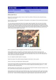
Look at all that nasty sealant my old mechanic used:
A quick look inside reveals: the crankshaft (1) and oil pump/distributor<br />
drive (2) sprockets, the timing chain itself (3), the chain limiting pin (4) and the<br />
tensioner shoe fastening bolt (5):<br />
5<br />
2<br />
4<br />
3<br />
1<br />
Different manufactures use different tensioner nut dimensions. So far I’ve<br />
seen having 12mm, 13mm and 9/16” heads. Mine had a 13mm nut:<br />
Use the 10mm socket to remove the tensioner fastening nuts before<br />
pulling it off the block:
Use the 13mm long socket to remove the crankcase ventilation system<br />
<strong>co</strong>ver <strong>co</strong>mplete with the oil dipstick and vent hoses. That big hose is supposed<br />
to go to the air filter, but this engine had so much blow-by that it kept fouling the<br />
carb with oil so I opted by letting it discharge to open air:
Both the camshaft and oil pump drive sprockets have these special lock<br />
washers to keep their bolts from <strong>co</strong>ming loose. Use a <strong>co</strong>ld chisel and tap with a<br />
hammer to unfold the washers and expose the bolts:
Take off the chain limiting pin with the aid of a 10mm wrench (spanner, if<br />
you haul from England, S<strong>co</strong>tland, Wales, Ireland, Oz or anywhere in Europe ☺):<br />
Undo the tensioner shoe fastening bolt with a 17mm socket and remove<br />
the shoe:
Use a screwdriver to lock the chain and use the 17mm socket to loosen<br />
both the camshaft and oil pump drive sprocket bolts, but don’t drive them out all<br />
the way:
Now remove the bolt and take out the pump drive sprocket:<br />
…Followed by the crankshaft sprocket…
…And finally remove the camshaft sprocket to withdraw the timing chain<br />
from the engine block:<br />
The nuts holding the camshaft bearing assembly are then removed with<br />
a 13mm socket; preferably by inverting the tightening order shown in the box:
After which the bearing assembly can simply be lifted out, exposing the<br />
valve rockers:<br />
The cylinder head bolts can be very tough to remove, so use a 19mm<br />
socket along with an extension and a big cheater bar to persuade them:
I <strong>co</strong>uld have removed the intake and exhaust manifolds, but to tell you<br />
the truth they give better grip when removing the head:
Damn! no wonder why No. 2 cylinder had no <strong>co</strong>mpression ☺…<br />
We’re pretty much done with the upper side, so now we turn the engine<br />
upside down to remove the oil sump nuts with the aid of a 10mm socket:
Pry on the sump a little…<br />
And out <strong>co</strong>mes the sump or oil pan like they say in some places:
Oh, once the block is inverted, the distributor drive gear should fall by<br />
itself…<br />
Use the 13mm socket to loosen the oil pump bolts and finally remove the<br />
pump:
In this position the crankcase vent system return tube is easily removed:
A quick spray of carb cleaner to get things tidy before I show you<br />
something…<br />
Here it is… The main bearing caps are marked with these notches<br />
ac<strong>co</strong>rding to their position, so don’t mix them up! No. 1, 2, 3 and 4 caps are<br />
marked with 1, 2, 3, and 4 notches while No. 5 cap is marked with two notches,<br />
spaced some 10mm one from each other:<br />
No. 5 cap<br />
No. 4 cap
used:<br />
Connecting rods are also marked, but in this case matching numbers are<br />
nuts:<br />
A 14mm or 9/16” socket is required to remove the <strong>co</strong>nnecting rod cap
To avoid gouging the journals, I put a piece of 8 mm (3/8”) ID hose on<br />
each <strong>co</strong>nnecting rod bolt before removing the crankshaft:<br />
Use a 17mm socket to loosen the main bearing cap bolts and remove all<br />
of the caps:
The crankshaft can now be lifted from the block…<br />
…Followed by the thrust half-rings which limit the crankshaft endplay.<br />
There’s one on each side of the No. 5 main journal:
The piston-<strong>co</strong>nnecting rod group can now be pulled out from the block<br />
(engine inverted in picture)…
I didn´t take any pictures of the process, but No. 1 piston was one hell of<br />
a bugger to remove… The oil <strong>co</strong>ntrol rings were broken in bits and those bits<br />
kept the piston from being withdrawn easily, so I pulled the piston up (engine<br />
inverted, remember?) until the piston hit the journal casting in order to pick the<br />
bits up with the aid of a magnetic parts retriever and a small screwdriver. Even<br />
after I did this I <strong>co</strong>uldn’t help but scratch the cylinder a little bit, no biggie since<br />
I’m having the block bored and honed… With the pistons out its time to remove<br />
the shell bearings from the main journals and the disassembly procedure is<br />
almost finished…<br />
A while ago my oil pressure transmitter broke, all parts stores asked an<br />
arm and a leg for a new one so I bought a mechanical gauge for less than half<br />
the <strong>co</strong>st of a lone electric transmitter. That´s why the mushroom-shaped thingy<br />
isn’t shown in the pics…<br />
Anyway, the transmitter needs to be removed before taking the block to<br />
the rebuilder, so use a 13/16” spark plug socket on the low oil pressure warning<br />
light switch and a 17mm socket to remove the tee fitting, which is held to the<br />
block by a banjo bolt (very similar to those used on brake systems). The low oil<br />
pressure switch is shown in the following picture right under that brass<br />
<strong>co</strong>mpression fitting:
Use a 13mm socket to loosen the two bolts that hold the oil pump drive<br />
shaft thrust plate to the engine block, remove the thrust plate and finally<br />
withdraw the shaft from the block to finish the disassembly operations. Of<br />
<strong>co</strong>urse the main engine subassemblies still need to be torn down, but that will<br />
be addressed in the next chapter.<br />
FINAL NOTE:<br />
All the procedures described in this article, with some logical exceptions<br />
such as fuel/ignition systems, valvetrain, electronics, among others, can be<br />
applied to any of the 1700 engines: Carb’d, SPFI (TBI) or MPFI.<br />
Alejandro Gabatel, July 2006.-