A ...GadgetBoy's Niva 1.7TBi 101 This - Niva Manuals
A ...GadgetBoy's Niva 1.7TBi 101 This - Niva Manuals
A ...GadgetBoy's Niva 1.7TBi 101 This - Niva Manuals

You also want an ePaper? Increase the reach of your titles
YUMPU automatically turns print PDFs into web optimized ePapers that Google loves.
GadgetBoy’s <strong>Niva</strong> <strong>1.7TBi</strong> <strong>101</strong><br />
<strong>This</strong> document is intended to explain the voodoo magic that is the<br />
GM/Lada Throttle Body Injection system as fitted to the <strong>Niva</strong>. It<br />
does not cover the Bosch Sequential system however the theory is<br />
the same. <strong>This</strong> article is not a repair manual nor is it intended to be<br />
however it may assist you in diagnosis of a fault and enable you to<br />
understand what the system does and how it does it. Remember, if<br />
you fiddle with anything it’s your responsibility.<br />
TBI Throttle Body Injection is a very versatile, highly adaptable form of<br />
electronic controlled mechanical fuel injection. TBI provides the optimum<br />
mixture ratio of air and fuel at all stages of combustion. TBI has immediate<br />
response characteristics to constantly changing conditions and ensures the<br />
engine runs as close as possible to a stochiometric air / fuel mixture ratio,<br />
greatly reducing exhaust gas emissions. Because its air / fuel mixture is so<br />
precise, based upon much more than simple engine vacuum and other<br />
mechanical metering means, TBI naturally enjoys an increase in fuel economy<br />
over a simple mechanical form of fuel introduction such as an outdated<br />
carburetor.<br />
The TBI form of EFI is controlled by the ECU (Electronic Control Unit) which<br />
controls the TBI based EFI system through all stages of operation according<br />
to data received regarding the current state of engine performance, speed,<br />
and load. The main component of this system is the TBI throttle body injector,<br />
which is mounted on top of the intake manifold, much like a carburetor. The<br />
throttle body injector is composed of two different parts; the throttle body itself,<br />
and the injector assembly. Hard to understand, isn't it? The throttle body is a<br />
large throttle valve which is controlled by a simple mechanical linkage to the<br />
accelerator pedal. Depressing the accelerator pedal will force the throttle<br />
valve open further and further, increasing the flow of air through the throttle<br />
valve and instructing the ECU to add more fuel, thus producing more power,<br />
faster speed, and acceleration.<br />
Attached to the body of the TBI unit are two sensors; the TPS throttle position<br />
sensor, and the IAC idle air control assembly. The ECU uses the TPS to<br />
determine the accurate position of the throttle body valve, it's degree of<br />
cycling, and how open it is (0% to 100%). The ECU takes readings from the<br />
IAC in order to maintain a constant idle speed during normal engine operation,<br />
during all stages of power, load, and combustion.<br />
The fuel metering assembly contains a fuel pressure regulator (FPR) which<br />
dampens the pulsations and turbulence generated from the very high<br />
pressure fuel pump. Think of the FPR as a conditioner that smoothes out the<br />
flow of fuel from the outside to the inside of the fuel metering assembly. The<br />
FPR also maintains a constant, steady pressure at the injector assembly. A<br />
single fuel injector is mounted over the throttle valve, synchronized, and<br />
raised slightly over a venturi (narrowing radius) throat. The injector is
controlled by the ECU through an electrically initiated solenoid (switch). The<br />
precise amount of fuel delivered by each injector is varied by the amount of<br />
time that the solenoid holds the injector plunger open for operation.<br />
A high pressure, high volume electric fuel pump is used with the TBI system.<br />
<strong>This</strong> pump is located within the fuel tank itself (which can be a bugger if you<br />
have to replace it). Once the ignition key is inserted into the ignition, and the<br />
ignition moved to the I position, the fuel pump relay instantly initiates the<br />
pump, beginning the transfer of fuel (via the pump) from the tank to the<br />
injector. A safety relay in the system shuts the pump off after two seconds, to<br />
keep the fuel from flooding. Failure of the fuel pump relay will allow the fuel<br />
pump to operate only after four pounds of oil pressure have built up. A high<br />
capacity fuel filter, similar to an in-line variety, is located on the left side of the<br />
vehicle, at the rear of the engine.<br />
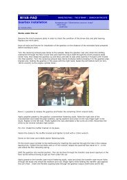
Two common mistakes when working with the EFI system. The fuel system is<br />
pressurized. If you remove a fuel line, you could/will get a face full of fuel! The<br />
fuel pump used on the EFI system is much more powerful than that found on<br />
a carburetor installation. For this very reason, the second problem is that you<br />
cannot use a EFI fuel pump to feed a carburetor, and you cannot use a<br />
normal carburetor mechanical style fuel pump (low pressure) to feed an EFI<br />
system. In order to work on any part of the EFI system, you must first<br />
depressurize your fuel system!!!!!<br />
The ECU found in the <strong>Niva</strong> has the capability to 'learn' or modify it's<br />
programming with regard to differing fuel requirements over time. Don't get<br />
excited. <strong>This</strong> is not HAL from 2001: A Space Odyssey, and it's certainly not<br />
some super advanced neural net processor like the T800 Endoskeleton had in<br />
Terminator and T2. It's quite a bit simpler, but it’s a complex computer<br />
nonetheless, and it can adjust to different conditions easily. It learns, just like<br />
a human child, and that's the best way to put it. It doesn't forget when you turn<br />
your car off either. But, if you ever change your battery, or your battery goes<br />
dead for any reason, your computer will lose it's stored 'memory' and will have<br />
to relearn everything. It's a quick learner, but it's something you don't really<br />
want to go through all the time.<br />
The computer's instructions are contained on a PROM (Programmable Read<br />
Only Memory), which means that the computer can change it's operation<br />
according to pending needs. It then stores this new information, and how it<br />
should act, on the PROM chip. Since the PROM isn't volatile, it doesn't lose<br />
it's information when the battery power is cut off or the keys are taken out of<br />
the ignition.<br />
But the computer takes a little while to adapt. So if you add a snorkel and the<br />
car doesn't feel right, don't get depressed. The computer has just been<br />
handed a new parameter, it's working under new data and conditions, and it<br />
could take it a little while to figure out that the changed air flow isn't just a<br />
fluke, and that it should adjust to the new 'constant', but adjust it will. Be<br />
patient. The computer can make up for quite a bit of ham fistedness, but only<br />
to a limit.
And after that limit is exceeded? Well, you could always learn to program your<br />
own chips... But I don't think it will come down to getting that serious.<br />
The system is very adaptable. The more you get away from the original<br />
operational parameters of the stock motor, the more the computer has to<br />
adapt. The more it has to adapt, the closer it gets to the point where it simply<br />
cannot adapt. If this limit is reached, and the computer cannot adapt any<br />
more, the ECU does the equivalent of a confused child in school. It raises it's<br />
hand and says "I don't understand what to do!" by turning on that annoying<br />
little "CHECK ENGINE" light.<br />
Most people think that the CE light is a bad thing. <strong>This</strong> isn't true. While it can<br />
indicate a possible malfunction (repair or replacement) of a component within<br />
the system, it can also be a way to talk to your computer. A primitive way, but<br />
a good way nonetheless. We'll get to that later.<br />
Think of your CHECK ENGINE light not as an indicator of failure, no, instead<br />
think of it as a text message from your ECU. When someone wants to talk to<br />
you, they text you, don't they? Your mobile on your belt vibrates or beeps or (if<br />
you are a total poser), plays some musical tune (like Crazy Frog...) that totally<br />
annoys everyone within listening distance. Well, think of the CE light as the<br />
same thing as a text from the ECU, only no vibration (you hope no vibration!)<br />
and no music. The CE is simply the ECUs way of saying "Hey, got a second?<br />
I need to talk to you!" It can't play a musical tune, so it does the only thing it<br />
can to get your attention; it flashes the CE light and keeps it lit until you<br />
answer its text.<br />
It could be important, it could be minor. But the important thing to understand<br />
and to remember is that your ECU is asking you for a few minutes of your time<br />
in order to talk over some really important stuff. If you ever see your CE light<br />
come on, I think you need to stop what you're doing and have a chat with your<br />
computer. You do this with a paper clip! In the left hand footwell on the A-<br />
Panel there is a chunky plastic cover attached with Velcro or screws. Behind<br />
this you’ll find a fuse box and a weird connector. <strong>This</strong> connector is your door<br />
to a beautiful relationship with your ECU. Make sure the ignition is off and get<br />
your paper clip and unfold it and re-bend it into a “U”. Now insert the ends into<br />
the two left most contacts on the bottom row of the weird connector. <strong>This</strong><br />
simple action translates the computer's language into something you can<br />
understand. The computer will talk to you in very short codes, called either<br />
error codes or trouble codes. There is no speech involved, but the computer<br />
will 'flash', blink on and off, your CE light. A long flash is read as the 'tens'<br />
place, and a short flash is the 'ones' place. So, if you are talking to your<br />
computer and the computer flashes the CE light two long times followed by<br />
three short blinks, then that is Code 23. Understand? It's not that hard. The<br />
codes are listed at the end of this document.<br />
So, the next time that your computer wants to talk to you, listen! The computer<br />
is your friend and you don't ignore friends when they need to talk. And make
sure that your CE light is working properly. Remember, if the bulb is out, your<br />
ECU could be trying to talk to you, but you'll never know it!<br />
Think of the ECU as a spider, in a web. At each end point of the web is a<br />
sensor or other control device. When something causes a disturbance in the<br />
web, the 'vibration' or sensor reading is sent down the 'web' to the 'spider'<br />
(ECU) which reads the information and reacts accordingly. Now, how TBI gets<br />
its input, well, that is supplied by various sensors located around the engine,<br />
in the engine bay, and around the vehicle itself. Let's talk about some of those<br />
now...<br />
Sensors, Inputs and Outputs Used<br />
TPS - Throttle Position Sensor, the TPS measures the position of the throttle.<br />
Really complicated stuff there. The position reading indication sent by the TPS<br />
to the ECU determines the amount of fuel to order the injector to inject, and<br />
modifies the duty cycle of the injector as needed. The degree of cycling of the<br />
throttle body valve is used to compute the duty cycle of the injector during<br />
high pressure fuel firing.<br />
CTS - Coolant Temperature Sensor, the CTS measures engine coolant<br />
temperature.<br />
MAP - Manifold Absolute Pressure, the MAP sensor measures the amount of<br />
load that is on the engine by sensing the difference between the pressure in<br />
the intake manifold and atmospheric pressure. It compares what's going on<br />
inside (kinetic) with what is going on outside (ambient). The MAP controls fuel<br />
mixture and timing. The MAP measures vacuum in the manifold.<br />
O2 - Oxygen Sensor, the O2 sensor is mounted in your exhaust manifold or<br />
exhaust pipe. The O2 sensor measures the amount of oxygen in the exhaust<br />
stream. Too much oxygen indicates not enough fuel or a lean condition. Too<br />
little oxygen indicates too much fuel or a rich condition. The ECU then takes<br />
steps to correct this problem by adjusting the air / fuel (mixture) ratio.<br />
The ECU also makes use of other inputs to determine proper fuel<br />
requirements. They are as follows:<br />
• Absolute Engine RPM is obtained from data received from the ignition<br />
module.<br />
• Battery Voltage is supplied to the ECU.<br />
• The ECU knows when the engine is trying to start and adjusts fuel<br />
accordingly thanks to communication with the crank sensor.<br />
The ECU controls the following items to maintain good power, mileage, idle<br />
and favourable emissions.<br />
Fuel Injector - The ECU controls the amount of time that the injector is<br />
spraying fuel. <strong>This</strong> amount of time is called the 'duty cycle' of the injector.<br />
Within some parameters, it can be overdriven to increase performance, but<br />
too much is not a good thing. The faster an injector is forced to fire, the less<br />
efficient it becomes.
IACS - Idle Air Control Sensor, the IACS is an adjustable air leak into the<br />
engine. It is a power valve which moves back and forth, constricting and<br />
enlarging, in order to adjust the air mixture. The ECU controls the leak to get a<br />
good idle. The readings from the IAC allow the ECU to adjust the motor's<br />
operations and idle accordingly.<br />
MATS - Manifold Air Temp Sensor- Also the Manifold Absolute Temperature<br />
Sensor, provides input on manifold temperature and allows the ECU to adjust<br />
mixture accordingly.<br />
Ignition Timing - the ECU controls the amount of timing advance or retard<br />
needed depending on engine RPM, power load and detonation detected.<br />
Timing will be advanced as needed to meet performance load parameters. It<br />
will be retarded, again as needed, to minimize or eliminate detonation.<br />
Idle - The ECU also has control over the idle RPM, for example when the<br />
engine is cold it idles a little higher. Temperature readings to determine if an<br />
engine is cold or not are taken from the coolant temp sensor, and from the<br />
oxygen sensor. Once temperature reaches operating ranges, the ECU idles<br />
the engine back down.<br />
Fuel Pump - The ECU also controls the fuel pump, turning it on before start,<br />
and keeping it on during cranking and run. Fuel pump pressure is also<br />
controlled by commands sent to the pump by the ECU. More load equals<br />
greater fuel pressure.<br />
VSS - The Vehicle Speed Sensor, which tells the ECU whether the engine is<br />
under load or on the over run.<br />
OA -Octane adjuster. DO NOT TOUCH THIS!<br />
Emissions Canister purge<br />
The ECU has the following outputs to help us. <strong>This</strong> is data that the ECU sends<br />
to the driver / operator as part of it's operation:<br />
CE - Check Engine light. It warns you of malfunctions with the system. When<br />
you see this light come on, get your paper clip.<br />
ALDL - Assembly Line Diagnostic Link. <strong>This</strong> is the proper name for the weird<br />
connector. As well as using the paper clip to get codes from the CE light this<br />
is a data interface you can connect a scanner to or a computer with a suitable<br />
software package. <strong>This</strong> will give you considerably more information than the<br />
CE light. It can even be used to drive “Fast and Furious” style digital<br />
dashboards.
Reference.<br />
Error codes.<br />
Code Explanation<br />
12 No spark pulses at CPU or else good system, no codes<br />
13 Oxygen sensor output remained at .35-.55 volts for more than one<br />
minute after warmup. Possible open circuit.<br />
14 Coolant sensor indicated a temperature above 130C for 3 seconds<br />
after engine ran for 20 seconds. Probably a short<br />
15 Coolant sensor indicated a temperature below -30C for 3 seconds<br />
when MAT > - 13 or engine running over 1 minute. Probably open<br />
circuit<br />
21 Throttle pos sensor above 2.5 volts for 2 seconds when engine speed<br />
below 1600 rpm<br />
22 Throttle pos sensor below .2 volt for 2 seconds while engine running<br />
23 MAT sensor shows < -30 degrees C for 3 seconds after engine running<br />
1 minute or coolant > 30C. Probably an open circuit.<br />
24 No speed sensor pulses when engine between 2000-4000 rpm, throttle<br />
closed, high vacuum, not in neutral and all for 5 seconds<br />
25 MAT sensor showed above 145 degrees C for 2 seconds after engine<br />
ran for over 1 minute. Possible short circuit.<br />
33 MAP sensor voltage too high (> 4.00 v). Possible vacuum leak to<br />
sensor or faulty sensor.<br />
34 MAP sensor voltage too low (< 0.25 v) with ignition on or engine<br />
running >1200 rpm and throttle open >20%<br />
35 Closed throttle idle speed is more than 75 rpm above or below correct<br />
value for more than 45 seconds<br />
41 No Crankshaft reference pulses. Ignition voltage < 11 volts etc.<br />
42 Open or short on EST or BYPASS line to ignition module.<br />
44 O2 sensor showed < 0.250 volt for over 20 seconds while operating<br />
closed loop<br />
45 O2 sensor showed > 0.550 volt for over 50 seconds while in closed<br />
loop with engine running over 1 minute and throttle open more than 2%<br />
51 Check that CALPAK is in place, fully inserted, and no bent pins<br />
53 Car's alternator has produced >16.9 volts for over 2 seconds. Check<br />
charging system<br />
54 Octane adjuster signal too high or too low.<br />
55 ECU A to D error. Check ECU grounds, or excessive input voltage
The Paper Clip trick.<br />
Note: The connector is upside-down in the <strong>Niva</strong>.<br />
Build your own ALDL interface.
Software<br />
There are many software packages available that will enable you to read the<br />
information your ECU provides. As well as outputting error codes the ECU<br />
also outputs realtime information of all the sensors and current parameters,<br />
much like the telemetry of an F1 racing car! (I kid you not). Using the above<br />
interface, which can be built for about $5, and suitable software you can<br />
monitor this information on a PC or laptop. Simple handheld scanners that will<br />
display basic information can be bought for as little as $20.<br />
As I said, there are many packages available in freeware, shareware and<br />
commercial forms. Simply Google for OBD software and you’ll see what I<br />
mean. My personal favourite is EFiLive V4. http://www.efilive.com Version 4 is<br />
the ALDL/OBD version.<br />
EFiLive is a commercial package. Yes! It costs money! However it’s only<br />
about $140 and it’ll pay for itself the first time you actually need it! Not only<br />
that but it’s damn good fun too!<br />
Once you have the software you will need a “definition file” for the <strong>Niva</strong>.<br />
Here’s one I prepared earlier: http://www.turbo-nutter.com/nivalive.zip<br />
Here’s a screenshot to make you drool!<br />
As well as displaying live information EFiLive can also record the telemetry<br />
and you can play it back later in the comfort of your living room.
Interfaces<br />
You can buy interfaces/cables for about $20 but you can also build one using<br />
the circuit diagram above. The components will cost about $5. I’m no wizard<br />
with a soldering iron but I managed it!<br />
<strong>This</strong> is now permanently mounted in my car in a little box immediately below<br />
the ECU diagnostic port.<br />
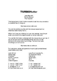
Parts<br />
When you work out you need a Coolant Temperature Sensor (for example)<br />
you need to get able to get one! Alan Bird at Lada UK http://www.lada.co.uk<br />
has them and will ship worldwide. Now I don’t want to do Alan out of business<br />
(he’s an excellent chap) but …… if you’re in Australia (for example) you may<br />
not want to wait 3 weeks for something to arrive! REMEMBER the <strong>Niva</strong> TBi<br />
system is a bog standard off-the-shelf GM system. The parts you need are in<br />
thousands of cars! A good motor parts shop will have either the original GM<br />
part or an aftermarket replacement. The trick is not to ask for a Lada part …..<br />
believe me, you will get funny looks and scratched heads! Bring the original to<br />
the motor parts shop, find the oldest assistant and ask for “one of these”<br />
please. Failing that, any early 90’s GM car in the junkyard should have what<br />
you need.<br />
The one exception to this is the ECU itself. It’s not the ECU that’s unique it’s<br />
what’s known as the “calibration module”. <strong>This</strong> is what programs the ECU to<br />
the <strong>Niva</strong>. If you have managed to toast your ECU, which is not easy to do I
may add, the chances are the calibration module is OK. It is possible to get<br />
another ECU and swap the module. I absolutely, totally and utterly do NOT<br />
recommend this but it is possible. Do this at your own risk!<br />
One final note. If you’re reading this article from a CD you purchased off eBay<br />
you’ve been had! <strong>This</strong> article and a wealth of <strong>Niva</strong> documentation are<br />
available FREE from http://www.turbo-nutter.com<br />
Have fun,<br />
GadgetBoy<br />
ladaniva@turbo-nutter.com<br />
<strong>This</strong> document was re-written for the <strong>Niva</strong> from Black Echo’s article<br />
http://www.goingfaster.com/spo/tbi.html with his kind permission.