Transmitter Brochure - TRANSRADIO
Transmitter Brochure - TRANSRADIO
Transmitter Brochure - TRANSRADIO

Create successful ePaper yourself
Turn your PDF publications into a flip-book with our unique Google optimized e-Paper software.
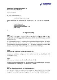
ALL<br />
UNDER ONE ROOF<br />
<strong>TRANSRADIO</strong> – We have your Solution
CONTENT<br />
DRM (Digital Radio Mondiale) – Radio goes future – we show IT ............4<br />
❙ Overview of the DRM Solution ...............................................................5<br />
❙ <strong>TRANSRADIO</strong> Rides on DRM Potential ...............................................6/7<br />
❙ DRM – The Economical Way to reach your Listeners.............................8<br />
❙ SFN – Extend the Coverage ....................................................................9<br />
❙ Fraunhofer DRM ContentServer R4.............................................10/11<br />
The new DRM DMOD3 – The All in One Solution....................................12<br />
❙ Features..................................................................................................13<br />
❙ Supported DRM Modes.........................................................................13<br />
❙ Harddisk-free Design, VSWR Measurement ........................................14<br />
❙ DRM Reserve and Fall Back Systems....................................................15<br />
❙ Optimization of the DRM Spectrum ......................................................16<br />
❙ Automatic Equalizer Adjustment – Speed up your Business..............17<br />
TRAM Premium Line – Pure Efficiency in all Modes ...............................19<br />
❙ TRAM Premium Line Highlights ......................................................20/21<br />
❙ Paralleling Unit ......................................................................................22<br />
❙ Riding the Longwave.............................................................................23<br />
❙ Fraunhofer DT 700 DRM Monitoring Receiver......................................24<br />
❙ Remote Control and Error Tracking via SNMP and HTML ...................25<br />
AM Antennas from <strong>TRANSRADIO</strong> – Designed for DRM .........................26<br />
Antenna Tuning Devices, Diplexer, ENW ................................................27<br />
DRM Consulting – Ask the Experts...........................................................28<br />
Turnkey-ready Solution from the Market leader......................................29<br />
Technical Data DRM DMOD3....................................................................30<br />
Ports and Connectors DRM DMOD3 ........................................................31<br />
3
DRM (DIGITAL RADIO MONDIALE) –<br />
Radio goes future – we show IT<br />
The major advantage of LF, MF and HF broadcasting in the<br />
frequency range below 30 MHz is the huge achievable<br />
coverage. While all other technologies need an extensive network<br />
with a high number of transmitters, AM broadcasting requires just<br />
a few transmitters, providing a program to particular target groups<br />
in a large geographical area. Because listeners were accustomed<br />
to the high quality of VHF/FM broadcasting, upgrading AM with a<br />
new technology was required to deliver the same high standards.<br />
Implementing the digital broadcasting technology DRM gives<br />
substantial improvements in audio and reception quality.<br />
❙<br />
❙<br />
❙<br />
❙<br />
❙<br />
❙<br />
Robustness in fading channels<br />
Significant improvement in audio quality<br />
Power savings at the transmitter site<br />
Service related data (service labels, alternative frequencies and<br />
language information)<br />
Data services (pictures, text- and traffic information)<br />
News Service Journaline TM<br />
Optional Fraunhofer<br />
DRM<br />
ContentServer TM R4<br />
MDI<br />
data<br />
Digital Radio Mondiale (DRM) is the name of the<br />
international consortium, which defined the standards<br />
for digitalisation of AM broadcasting. DRM was founded<br />
in 1998 and developed a digital radio standard which is endorsed<br />
by the IEC, ETSI and ITU. <strong>TRANSRADIO</strong>, formerly TELEFUNKEN<br />
SenderSysteme Berlin, as a founding member of this consortium,<br />
has tremendously influenced this standard with its experience and<br />
knowledge in broadcasting. <strong>TRANSRADIO</strong> has established itself as<br />
the leading DRM provider. Today <strong>TRANSRADIO</strong> has the highest<br />
number of installed DRM transmitters in service.<br />
Audio<br />
4
OVERVIEW OF THE DRM SOLUTIONS<br />
GPS-antenna or<br />
external clock<br />
TRAM TX1<br />
RF drive<br />
DRM DMOD3<br />
ENV1<br />
RF out<br />
Paralleling<br />
unit<br />
Antenna<br />
Antenna<br />
RF<br />
ENV2<br />
TRAM TX2<br />
RF out<br />
RF drive<br />
RF back<br />
(directional<br />
coupler)<br />
Optional<br />
Fraunhofer DRM<br />
Monitoring Receiver<br />
DT 700<br />
RF back<br />
5
<strong>TRANSRADIO</strong> RIDES ON DRM POTENTIAL<br />
<strong>TRANSRADIO</strong> has<br />
established itself as the<br />
world’s leading DRM provider.<br />
Today, <strong>TRANSRADIO</strong> has<br />
the highest number of<br />
installed DRM transmitters<br />
in service.<br />
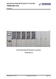
DRM Medium Wave Transmitting Station<br />
Cremlingen MW 800kW<br />
MW transmitter<br />
TRAM/P 800<br />
Carrier power<br />
of 800kW<br />
(>400kW DRM)<br />
in Cremlingen/<br />
Braunschweig<br />
(Germany)<br />
Marnach MW 600kW<br />
MW transmitter<br />
TRAM/P 600<br />
Carrier power<br />
of 600kW<br />
(>300kW DRM)<br />
in Marnach<br />
(Luxembourg)<br />
Heusweiler MW 400kW<br />
MW transmitter<br />
TRAM/P 400<br />
Carrier power of<br />
400kW<br />
(>200kW DRM)<br />
in Heusweiler<br />
(Germany)<br />
6<br />
Please find more references on our
DRM Long Wave Transmitting Station<br />
Zehlendorf LW 500kW<br />
LW transmitter<br />
TRAM/P 500L<br />
Carrier power<br />
of 500kW<br />
(>250kW DRM)<br />
in Zehlendorf<br />
(Germany)<br />
Donebach LW 500kW<br />
LW transmitter<br />
TRAM/P 500L<br />
Carrier power<br />
of 500kW (>250<br />
kW DRM)<br />
in Donebach<br />
(Germany)<br />
Summerhill LW 300KW<br />
LW transmitter TRAM 300L<br />
Carrier power of 300kW<br />
(>150 kW DRM)<br />
in Summerhill (Ireland)<br />
website www.transradio.de/references<br />
7
DRM – THE ECONOMICAL WAY TO REACH YOUR LISTENERS<br />
The DRM power is normally given as the<br />
average power of the digital modulation.<br />
Because of the high modulation peaks of<br />
the DRM signal, the average power is<br />
significantly lower than for the same<br />
transmitter operating in the analog AM<br />
mode. In general a DRM COFDM<br />
waveform has a peak to average ratio<br />
of about 10 dB. Thus a standard DRM<br />
transmitter with a carrier power of<br />
100kW and 100% modulation reaches a<br />
peak power of 400kW. The DRM power<br />
of such a transmitter is only 40 kW.<br />
As a result, for the same coverage, up to<br />
60% of the power can be saved running<br />
an AM transmitter in DRM.<br />
In contrast to standard transmitters,<br />
<strong>TRANSRADIO</strong>’s TRAM family of transmitters<br />
attain a DRM power of up to 73%<br />
of their nominal power with all quality<br />
requirements fulfilled: the MER value<br />
is well above the minimum DRM<br />
requirement and the out-of-band<br />
emissions are considerably within the<br />
DRM spectrum mask. This is possible<br />
due to the overmodulation capability<br />
of the TRAM transmitters and a<br />
peak-to-average ratio reduction scheme<br />
implemented in the DRM DMOD3.<br />
Thus, <strong>TRANSRADIO</strong>’s TRAM family of<br />
transmitters produce nearly two times<br />
the DRM power compared to a standard<br />
transmitter.<br />
8
SFN – EXTEND THE COVERAGE<br />
SFN-Berlin: 3 TRAM 10, 1485 kHz<br />
A single frequency network (SFN) is<br />
a radio network that operates several<br />
transmitters on a single frequency and<br />
has overlapping coverage areas. SFN’s<br />
are an efficient method of extending<br />
the coverage area without the need for<br />
additional frequencies. Signals arriving<br />
from transmitters outside the local transmitter<br />
area can reinforce reception and<br />
recover losses through local anomalous<br />
propagation effects. Any receiver in the<br />
coverage area of these transmitters will<br />
receive the signal from more than one<br />
transmitter. Different paths that arrive<br />
from distant transmitters in the SFN<br />
must arrive with a delay separation that<br />
is less than the guard interval duration,<br />
or otherwise inter-symbol interference<br />
occurs. To avoid interference, each<br />
station is run synchronously with the<br />
others using GPS as a reference clock.<br />
The built-in GPS receiver of the DRM<br />
DMOD3 from <strong>TRANSRADIO</strong> is<br />
implemented for single frequency<br />
networks. Tests in the medium wave<br />
band, conducted in cooperation with<br />
MEDIA BROADCAST GmbH and in the<br />
short wave band, in cooperation with<br />
the DRM consortium demonstrated the<br />
readiness of the DRM DMOD3 for all<br />
types of SFN's.<br />
9
OVERVIEW<br />
FRAUNHOFER<br />
DRM CONTENTSERVER R4<br />
Optional Fraunhofer<br />
DRM<br />
ContentServer TM R4<br />
MDI<br />
data<br />
Audio<br />
Overview of the DRM ContentServer TM R4<br />
GPS<br />
The system has<br />
3 major interfaces:<br />
Audio<br />
Data<br />
DRM<br />
AudioServer<br />
DRM<br />
Multimedia<br />
DataServer<br />
The Fraunhofer DRM ContentServer<br />
R4 is designed to meet all the demands<br />
of DRM broadcasters, DRM network<br />
providers and DRM transmitter<br />
operators with regard to DRM Multiplex<br />
generation. The system is typically<br />
located in the studio or a playout center<br />
or at the transmitter site – with full<br />
remote control for administration and<br />
data provision. The Fraunhofer DRM<br />
ContentServer R4 is based on robust<br />
and redundant 19” server hardware for<br />
reliable 24/7 operation.<br />
The Fraunhofer DRM ContentServer<br />
R4 provides triple functionality:<br />
DRM Multiplex Generator<br />
Config<br />
Interface<br />
FAC<br />
SDC<br />
MSC<br />
MDI / DCP<br />
Interface<br />
Remote<br />
Configuration/<br />
Administration<br />
DRM<br />
Modulators<br />
DRM Audio Server<br />
With multi-stream real time audio<br />
encoding<br />
DRM Multimedia Data Server<br />
Providing all standardized as well<br />
as proprietary mechanisms for<br />
data application import, preparation,<br />
encoding and broadcast<br />
DRM Multiplex Generator<br />
Managing the extensive DRM<br />
signalling capabilities, generating<br />
the full digital DRM Multiplex and<br />
providing standard MDI/DCP output<br />
streams.<br />
The system can easily be scaled to<br />
match individual requirements and to<br />
support proprietary data applications.<br />
Configuration and Administration:<br />
The system is designed to be administered<br />
remotely using any modern HTML<br />
browser. The system status is available<br />
via remote HTML interface (including<br />
detailed status information), automatic<br />
e-mail report system, local status monitor,<br />
relay board signalling and SNMP.<br />
Audio and Data Input:<br />
For audio input, the system supports up<br />
to 4 digital AES/EBU or up to 4 analog<br />
stereo signals. In addition, playlists and<br />
mp3 files can be uploaded to the system<br />
for offline audio encoding. Data for<br />
multimedia applications can be provided<br />
using a variety of standard protocols<br />
(e.g. FTP, HTTP, RSS, UECP, Leitungsprotokoll,<br />
Funkhaustelegramm). Powerful<br />
mirroring features provide automatic<br />
and scheduled data updates e.g. from<br />
FTP, HTTP and RSS sources on the web.<br />
DRM Multiplex Output via MDI/DCP:<br />
The complete digital DRM multiplex<br />
generated by the Fraunhofer DRM<br />
ContentServer R4 can be fed<br />
simultaneously to any number of DRM<br />
modulators or monitoring stations for<br />
multi-frequency or SFN broadcasts.<br />
The output stream uses the standardized<br />
MDI/DCP protocol supported by all<br />
standard compliant DRM modulators<br />
and monitoring equipment via UDP/IP<br />
based or serial connections.<br />
10
Features of the DRM ContentServer TM R4<br />
Public Network<br />
Content Contribution<br />
Firewall /<br />
Security<br />
Protected Privat Network<br />
Broadcast Distribution Chain<br />
Administration<br />
(Webbrowser)<br />
Time sync<br />
GPS, ntp<br />
Audio 1-4 Streams<br />
(live/playlist)<br />
Data Application<br />
DRM Text Messages<br />
News Service Journaline<br />
MOT Slideshow<br />
MOT Broadcast Website<br />
TPEG Traffic Information<br />
EPG-Electronic Program<br />
Guide<br />
TOP News<br />
TMC-Traffic Message<br />
Channel<br />
DRM Audio<br />
Server<br />
4 x (AAC, CELP,HVXC)<br />
DRM Multimedia<br />
Dataserver<br />
TM<br />
SNMP<br />
DRM Multiplex<br />
Generator<br />
Analoge/ Email Relay Local status/<br />
ISDN notification<br />
Modem<br />
card Config menu<br />
System Status<br />
MDI / DCP<br />
Local / long distance<br />
Any number of<br />
simultaneous<br />
outputs (SFN)<br />
IP uni-/multicast<br />
RS-232<br />
11
THE NEW DRM DMOD3 - THE ALL IN ONE SOLUTION<br />
12
OVERVIEW<br />
DRM DMOD3<br />
E<br />
E<br />
The aim of the new DRM DMOD3<br />
is to offer highly automated<br />
configuration procedures, maximum<br />
reliability, low power consumption, low<br />
heat dissipation and a compact and<br />
ergonomic design. All broadcasting<br />
modes are possible. The DRM DMOD3<br />
offers easy and fast switchover facility<br />
between analog AM, pure DRM, single<br />
channel or multi channel simulcast.<br />
Core features of the new DRM exciter<br />
are the automatic equalizer adjustment<br />
and the integrated antenna voltage<br />
standing wave ratio (VSWR) measurement<br />
capability, which offers a very<br />
precise and fast method to set up<br />
DRM equipment. The DRM DMOD3<br />
is designed for mounting in standard<br />
19” racks of 4U height.<br />
It eliminates the requirement for a<br />
separate RF processor and offers<br />
a significant reduction in external wiring.<br />
Low power consumption, reduced<br />
operating temperature and a higher<br />
MTBF have been achieved by<br />
implementing notebook technology<br />
components and a harddisk-free design.<br />
New Features:<br />
Operation modes<br />
❙ Operation modes AM, DRM, SCS and<br />
MCS<br />
Fast switchover<br />
❙ Fast switchover is accomplished in<br />
less than 5 seconds between all<br />
operation modes<br />
Automatic Equalizer Adjustment<br />
❙ Easy signal correction with automatic<br />
equalizer adjustment<br />
VSWR Measurement of the Antenna<br />
Integrated RF Processor<br />
❙ The DRM DMOD3 fits into a single<br />
4RU Case<br />
❙ Significant reduction of external wiring<br />
Low Power Consumption<br />
❙ Harddisk-free design<br />
❙ Use of notebook components<br />
Now all DRM-Modes fully supported!<br />
Ergonomic Design<br />
❙ Increased display size of 8.4”<br />
❙ Provides a resolution of 800x600 for<br />
easy readability<br />
❙ Simple to operate without the need<br />
of a external keyboard<br />
Improved Reliability<br />
❙ Harddisk-free design for better MTBF<br />
❙ Wide ambient temperature range<br />
up to 50 °C<br />
Mode A Mode B Mode C Mode D<br />
Nominal Bandwidth (9/10 kHz) ✔ ✔ ✔ ✔<br />
Half Bandwidth (4.5/5 kHz) ✔ ✔ ✔ ✔<br />
Double Bandwidth (18/20 kHz) ✔ ✔ ✔ ✔<br />
64QAM MSC, all Code Rates ✔ ✔ ✔ ✔<br />
16QAM MSC, all Code Rates ✔ ✔ ✔ ✔<br />
16QAM SDC ✔ ✔ ✔ ✔<br />
4QAM SDC ✔ ✔ ✔ ✔<br />
Standard Modulation ✔ ✔ ✔ ✔<br />
Hierarchical Modulation ✔ ✔ ✔ ✔<br />
Equal Error Protection ✔ ✔ ✔ ✔<br />
Unequal Error Protection ✔ ✔ ✔ ✔<br />
Long/Short Interleaving ✔ ✔ ✔ ✔<br />
✔ = supported<br />
13
VSWR MEASUREMENT, HARDDISK-FREE DESIGN<br />
Dual-flash storage architecture: Safe like a safe<br />
Harddisk-Free Memory Architecture<br />
The new memory architecture of the DRM<br />
DMOD3 offers maximum reliability due<br />
to the harddisk-free design. All necessary<br />
data to boot up and to run the DMOD3<br />
are stored on a static permanent storage<br />
(flash1), which has read only access.<br />
Inessential dynamic data for logging<br />
and configuration, which are written<br />
occasionally, are stored on a second<br />
flash memory (flash 2). This separation<br />
of the essential and inessential data<br />
on two flash storage devices was made<br />
to increase the reliability of the<br />
architecture, since the likelihood of<br />
failure of a flash memory is determined<br />
mainly by the number of write cycles.<br />
Example of an Antenna VSWR<br />
VSWR Measurement<br />
of the Antenna<br />
The DRM broadcast must be compliant<br />
with the ITU spectrum mask and<br />
requires low antenna VSWR. The DRM<br />
DMOD3 is capable of measuring the<br />
VSWR of the antenna during DRM<br />
operation and to show the result on the<br />
screen. This enables the broadcaster to<br />
monitor antenna matching during<br />
regular operation without additional<br />
measuring equipment.<br />
Furthermore the DRM spectrum is measured<br />
and is visualized by the integrated<br />
DRM DMOD3 web server.<br />
Mandatory<br />
- Read only<br />
Static permanent<br />
storage<br />
Startup<br />
Programs<br />
Permanent config<br />
Flash1<br />
Dynamic permanent<br />
storage<br />
Inessential<br />
for normal<br />
operation<br />
Log files<br />
Dynamic<br />
configuration<br />
Flash2<br />
Data Processing<br />
Memory Architecture<br />
Dynamic volatile<br />
storage<br />
Temporary data<br />
Fast logging<br />
RAM<br />
Disk<br />
14
DRM RESERVE AND FALL BACK SYSTEMS<br />
Active DRM Reserve<br />
MDI<br />
DRM DMOD3 -A<br />
The active DRM reserve offers a<br />
maximum of reliability for a DRM<br />
system. Two DRM exciters supervise<br />
each other during normal operation.<br />
In the unlikely event of failure of<br />
one DRM exciter, the remaining<br />
exciter takes over the service and<br />
keeps the transmitter(s) on air.<br />
In an active reserve, double<br />
exciter system the test points of<br />
the transmitter(s) are switched as well.<br />
MDI<br />
Audio<br />
Audio<br />
Supervision<br />
Link<br />
RF, Envelope<br />
Control<br />
Unit<br />
RF, Envelope<br />
TX<br />
Antenna<br />
DRM Exciter<br />
Fall-Back Solution<br />
The exciter fall-back solution gives<br />
the opportunity to fall back from<br />
DRM transmission to AM, DAM or<br />
AMC modulation in the unlikely<br />
event of failure of the digital exciter.<br />
In fall back mode the audio signal<br />
bypasses the digital exciter.<br />
The internal synthesizer of the transmitter<br />
provides the RF signal and the<br />
transmitter is kept on air by means of<br />
the internal AM modulator.<br />
MDI<br />
Audio<br />
DRM DMOD3 TX Antenna<br />
RF<br />
Envelope<br />
Audio<br />
Control Unit<br />
RF from<br />
TX-Synthesizer<br />
RF<br />
Envelope<br />
Audio<br />
Combination of Active DRM Reserve and DRM Exciter Fall-Back<br />
In order to further increase the reliability of the DRM system, the Active DRM Reserve and the Exciter Fall-Back Solution can be<br />
combined. In the unlikely case of the failure of both DRM exciters the internal synthesizer of the transmitter provides the RF signal.<br />
15
OPTIMIZATION<br />
OF THE DRM SPECTRUM<br />
The DRM DMOD3 provides automatic functions to pre-equalize the transmitted signal in order to minimize the out-of-band emissions.<br />
The aim of the pre-equalization process is to reduce the influence of linear and non-linear distortions on the DRM signal.<br />
The following pre-equalization functions are supported by the DRM DMOD3:<br />
Optimisation Process<br />
AM/AM AM/PM H (j) , DC<br />
Compensation of<br />
Non-linear Distortion I<br />
Compensation of<br />
Non-linear Distortion II<br />
Compensation of<br />
Linear Distortions<br />
Adjustment of the Time<br />
Delay and the DC Offset<br />
❙<br />
❙<br />
❙<br />
Measurement of the<br />
amplifier characteristic<br />
(AM/AM characteristic)<br />
Calculation of a<br />
correction curve<br />
Pre-equalization of the<br />
transmission signal<br />
❙<br />
❙<br />
❙<br />
Measurement of the<br />
incident phase<br />
modulation (AM/PM<br />
characteristic)<br />
Calculation of a<br />
correction curve<br />
Pre-equalization of the<br />
transmission signal<br />
❙<br />
❙<br />
Measurement of the<br />
envelope frequency<br />
response<br />
Calculation of an<br />
equalization filter to<br />
compensate the<br />
amplitude frequency<br />
response and the group<br />
delay distortions<br />
❙<br />
The DRM DMOD3<br />
offers a sophisticated<br />
algorithm for optimal<br />
adjustments between<br />
the delay differences<br />
of the amplitude- and<br />
phase signal as well<br />
as the DC offset.<br />
❙<br />
Pre-equalization of the<br />
transmission signal<br />
16
SPEED UP YOUR BUSINESS<br />
One Button Automatic Equalizer Adjustment<br />
Broadcast operators demand an automated<br />
configuration procedure for<br />
DRM equipment and the DRM DMOD3 is<br />
the answer. The DRM DMOD3 provides<br />
automated functions to pre-equalize<br />
the transmit signal in order to reduce<br />
out-of-band emissions. The equalizer<br />
adjustment can be performed<br />
automatically just by the push of a<br />
button.<br />
The DRM DMOD3 auto-adjust of the<br />
equalizer offers:<br />
❙ Automatic initial equalizer adjustment<br />
❙ Equalizer optimization during DRM<br />
operation<br />
❙ Adaptive equalization<br />
❙<br />
❙<br />
Automatic switching of up to three<br />
different test points<br />
Crucial parameters like time delay,<br />
DC offset and envelope frequency<br />
response are optimized in order to<br />
minimize out-of-band emissions<br />
DRM DMOD3<br />
MDI<br />
MDI Decoder<br />
&<br />
OFDM Generator<br />
I,Q<br />
Equalizer<br />
I-Q<br />
to<br />
A-Phi<br />
Conversion<br />
Phi<br />
A<br />
Delay<br />
Adjustment<br />
Envelope<br />
Filter<br />
Upsampling<br />
&<br />
RF-Output<br />
Phase<br />
modulated<br />
RF<br />
Envelope<br />
TX<br />
A-Phi<br />
Delay<br />
Filter<br />
Coefficients<br />
DC-Offset<br />
DRM DMOD3<br />
Auto - Adjust<br />
Test<br />
Point 1<br />
RF-Input<br />
&<br />
Downsampling<br />
Measuring Point<br />
Switching device<br />
Test<br />
Point 2<br />
Test<br />
Point 3<br />
Block Diagram of the Automatic Equalizer Adjustment<br />
17
TRAM PREMIUM LINE – PURE EFFICIENCY IN ALL MODES<br />
18<br />
TRAM 10 TRAM 50<br />
TRAM 100
OVERVIEW<br />
TRAM TX1<br />
TRAM TX2<br />
Many years of experience in the<br />
field of high power transmitters in<br />
conjunction with the latest state of the<br />
art transistor technology has paved the<br />
way for a future oriented and meanwhile<br />
well established solid state transmitter<br />
concept. As opposed to conventional<br />
transmitters the simple modular system<br />
of solid state medium wave transmitters<br />
from <strong>TRANSRADIO</strong> offers a maximum<br />
of flexibility and unsurpassed audio<br />
quality. The TRAM Premium line based<br />
on the new developed power modules<br />
secures optimized DRM parameter while<br />
achieving an outstanding overall<br />
efficiency in all operation modes.<br />
The TRAM Premium Line –<br />
optimized for DRM Transmission<br />
All TRAM Premium line transmitters are<br />
optimized for digital transmission and<br />
exceed the DRM recommendations.<br />
The layout, in standard 19" racks, allows<br />
for easy and comfortable access to all<br />
components and modules and results<br />
in exceptionally low space requirement<br />
for the respective power classes.<br />
The power amplifier stage offers true<br />
modular redundancy through the use of<br />
standardized 1 kW amplifier modules.<br />
Each individual module is equipped with<br />
an on-board PDM modulator and no<br />
quantization problems occur. Designed<br />
with a high power reserve capability,<br />
each module provides full signal quality<br />
on its own.<br />
TRAM 400<br />
19
TRAM PREMIUM LINE HIGHLIGHTS<br />
<strong>TRANSRADIO</strong><br />
TRAM-transmitters, prefered models<br />
Type<br />
No. of 50kW- Power blocks<br />
No. of identical power modules<br />
No. of driver modules<br />
Output power (other power classes on request)*)<br />
Frequency range<br />
LW<br />
MW<br />
Operation modes<br />
RF Output<br />
Modulation system<br />
AF range<br />
Connector<br />
Load impedance<br />
VSWR<br />
❙<br />
❙<br />
❙<br />
❙<br />
❙<br />
❙<br />
❙<br />
❙<br />
❙<br />
❙<br />
❙<br />
Outstanding efficiency and excellent performance<br />
data<br />
≥125 % positive peak programme capability<br />
DAM operating mode for further energy saving<br />
(standard for all models, DCC by jumper setting)<br />
Compact and service-friendly design, extremely<br />
low space requirement<br />
Modular design of the power amplifiers: standard<br />
1 kW plug-in power module, broadband over the<br />
whole MF range, no tuning of the modules is<br />
required. Integrated supervision and protection<br />
circuits are standard features.<br />
All transmitters are exclusively air-cooled utilising<br />
a unique internal air-flow system. Recycled air<br />
cooling by means of air-water heat exchangers<br />
available.<br />
Factory fitted and tuned to the desired operating<br />
frequency.<br />
Rugged construction with emphasis placed on high<br />
mechanical strength and stability.<br />
Combining stand alone transmitters by utilising an<br />
innovative paralleling unit (PU). No need for a highpower<br />
reject load.<br />
TRAM Premium line transmitters are also available<br />
as long wave broadcast transmitters (150 to 300<br />
kHz) and long wave communication transmitters<br />
(14 to 148 KHz)<br />
All TRAM Premium line transmitters are optimized<br />
for digital modulation techniques such as DRM.<br />
TRAM – Essentials at a Glance<br />
LW communication transmitters:<br />
LW broadcast transmitters:<br />
MW broadcast transmitters:<br />
Output power range:<br />
AF Frequency response<br />
AF harmonic Distortion (THD)<br />
Modulation capability<br />
Carrier shift (amplitude drop)<br />
RF harmonics and spurious emissions<br />
Signal to noise ratio<br />
Frequency stability<br />
AF Input<br />
Power supply<br />
Voltage<br />
Frequency<br />
Voltage variations<br />
Power factor<br />
Power consumption m = 0<br />
m = 1<br />
Overall efficiency**)<br />
Control<br />
Local<br />
Environmental<br />
conditions<br />
Cooling system<br />
Dimensions [mm]<br />
(LW TXs require more filter racks)<br />
Remote<br />
Temperature<br />
Relative humidity<br />
Installation altitude<br />
Width<br />
Depth<br />
Height<br />
14 kHz to 148 kHz<br />
150kHz to 300kHz<br />
525 kHz to 1710 kHz<br />
stand-alone version 5kW to 600 kW<br />
combined up to 2000 kW<br />
20
AM TRANSMITTERS – A SECURE INVESTMENT INTO THE FUTURE<br />
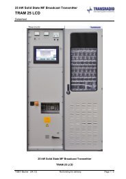
TRAM 5 TRAM 10 TRAM 25 TRAM 50 TRAM 100 TRAM 200 TRAM 300 TRAM 400 TRAM 500 TRAM 600<br />
1 2 4 6 8 10 12<br />
5 10 24 48 96 192 288 384 480 576<br />
– – 1 1 2 4 6 8 10 12<br />
5 kW 10 kW 25 kW 50 kW 100 kW 200 kW 300 kW 400 kW 500 kW 600 kW<br />
150 kHz to 300 kHz<br />
525 kHz to 1710 kHz<br />
Factory fitted and tuned to the determined operating frequency<br />
Components for change to other frequencies on request<br />
AM (A3E) – AM reduced power P/4 – DAM (X3E), i.e. dynamic carrier control – AM stereo capability, prepared for DRM<br />
7/8“ EIA 1 5/8“ EIA 3 1/8“ EIA 4 1/2“ EIA 6 1/8“ EIA 9“ EIA<br />
50 unbalanced<br />
VSWR 1.3 tuneable, automatic power reduction as a result of increasing VSWR during operation<br />
Pulse Duration Modulation (PDM)<br />
30 Hz to 10 kHz<br />
Changeover between a maximum of 2 band limiting filters on request<br />
0.5 dB, 30 Hz to 10 kHz, with band limiting filters switched off<br />
1% at m = 0,8<br />
100% continuously, + 125% peak programme capability<br />
1% with voltage regulation<br />
Standard: according to ITU-R SM 329 or better ( 50mW), FCC requirements on request<br />
60 dB referred to 100% Modulation<br />
Deviation 5Hz, external synchronisation of synthesizer possible<br />
600 balanced (can be changed inside the unit by jumper to 2000 )<br />
Adjustable from –10dBm to +10dBm referred to 100% modulation, switched coarse increments (5dB), fine adjustment by potentiometer<br />
Standard mains configuration: 3 N 400V;TN-S or TN-C, other voltages on request, TRAM 200 or higher MV supply preferred<br />
50Hz (60 Hz on request)<br />
5% with full performance; ± 10% with minor performance degradation<br />
0.9 0.95<br />
6.7 kW 12.2 kW 29,8 kW 57,5 kW 114,9 kW 229,9 kW 344,8 kW 459,8 kW 574,7 kW 689,7 kW<br />
10,0 kW 18.3 kW 44,6 kW 86,2 kW 172,4 kW 344,8 kW 517,2 kW 689,7 kW 862,1 kW 1034,5 kW<br />
> 75% > 82% > 84% 87%<br />
OFF/ON, full power/on, reduced power(P/n) – AM/DAM – selection local/remote<br />
Changeover between 2 AF band limiting filters – various status indications by LED<br />
Command input by floating contacts, same commands as for local control, indications by floating contacts<br />
RS 232 standard and BIT BUS, SNMP, HTML optional<br />
Standard: –10 °C to +50°C, other environmental temperatures on request<br />
maximum 95%, non-condensing<br />
Standard: maximum 2000 m, higher altitudes on request<br />
Air cooling (intake air from the room, exhaust air to the room, air duct system with blowers on request)<br />
600 600 1200 1800 3000 4800 6000 9600 10800 12000<br />
1000 1000 1000 1000 1000 1000 1000 1000 1000 1000<br />
2000 2000 2000 2000 2000 2500 2500 2500 2500 2500<br />
*) All other power ranges on request **) with standard cooling<br />
<strong>TRANSRADIO</strong> – RF and Power are our Strength<br />
21
PARALLELING UNIT<br />
The paralleling unit (PU) serves to<br />
combine two single transmitters to<br />
double the output power. Furthermore,<br />
it provides an active redundancy system<br />
to avoid a loss of transmission during<br />
maintenance schedules.<br />
The PU equipment contains a central<br />
control unit, a combining network and<br />
a compact balancing resistor.<br />
The load regulation of the central control<br />
unit ensures that both transmitters are<br />
levelled automatically to equal RF output<br />
powers and a minimum of power is<br />
lost on the balancing resistor. In the<br />
unlikely event of failure of one of the<br />
transmitters, a motorised RF switch will<br />
automatically switch the unaffected<br />
transmitter directly to the antenna and<br />
the faulty transmitter to a dummy load.<br />
The transmission continues and the<br />
faulty transmitter can be repaired whilst<br />
connected to the dummy load.<br />
OVERVIEW<br />
RFout<br />
Paralleling<br />
unit<br />
A<br />
RFbac<br />
(direct<br />
couple<br />
PU Control Unit<br />
22
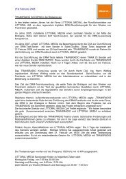
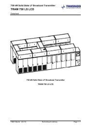
RIDING THE LONGWAVE<br />
Long Wave <strong>Transmitter</strong><br />
TRAM/P 500L (500kW)<br />
from <strong>TRANSRADIO</strong><br />
in Zehlendorf<br />
Longwave is well known for excellent<br />
ground wave coverage hence, offering a<br />
stable reception. DRM on LW combines<br />
the advantages of digital transmission<br />
with very good longwave propagation.<br />
On the other hand, narrow band<br />
longwave antennas with considerable<br />
mismatch even inside the transmission<br />
bandwidth are posing a big challenge to<br />
the broadcast industry. <strong>TRANSRADIO</strong><br />
has accepted this challenge and has<br />
successfully modernized several LW<br />
transmission stations with its DRM<br />
solution. The DRM installation on LW<br />
needs completely to fulfill the<br />
requirements concerning the out-ofband<br />
emissionsof ETSI EN 302 245-1 and<br />
ITU SM.1541. Therefore, <strong>TRANSRADIO</strong><br />
implements an Extension Network<br />
(ENW) to eliminate the disadvantages of<br />
the asymmetrical antenna impedance<br />
and to reduce mismatch. This results in<br />
a reduction of the standing wave ratio<br />
and a significant mask reserve. A world<br />
premier was achieved when the<br />
<strong>TRANSRADIO</strong> transmitter in Zehlendorf<br />
(Germany) broadcast for the first time<br />
DRM on long wave in accordance with<br />
the ETSI/ITU standard. Since then<br />
<strong>TRANSRADIO</strong> reconfirmed impressively<br />
its leading position with respect to LW<br />
and has modernized LW transmitting<br />
stations, for example, in Donebach,<br />
Aholming (Germany) and Summerhill<br />
(Ireland).<br />
Spectrum of the transmitted Signal in Zehlendorf<br />
Burg<br />
Mainflingen<br />
Kalundborg, DK<br />
Long Wave-Antenna<br />
in Zehlendorf (360m)<br />
Burg, Mainflingen and Kalundborg are Signals received from other Stations<br />
23
OVERVIEW<br />
FRAUNHOFER DT 700<br />
DRM MONITORING RECEIVER<br />
rive<br />
(directional<br />
coupler) Optional<br />
Fraunhofer DRM<br />
Monitoring Receive<br />
DT 700<br />
Concept<br />
The DRM Monitoring Receiver DT 700<br />
is a professional monitoring receiver<br />
perfectly suited for DRM reception and<br />
transmitter monitoring. It features<br />
a high performance front-end based on<br />
the latest direct sampling reception<br />
technology. Together with a 12-band<br />
fix-tuned preselector filter bank, the<br />
DRM Monitoring Receiver DT 700<br />
guarantees an outstanding reception<br />
performance and low phase noise.<br />
The receiver's signal processing is based<br />
on a Software Defined Radio (SDR)<br />
construction. Its core is an embedded<br />
Linux PC. The latter features an easy<br />
software update via built-in DVD drive.<br />
The highly reliable hardware is built<br />
for 24/7 continuous operation as is<br />
necessary for a professional broadcast<br />
environment. Based on the embedded<br />
Linux platform a web server allows easy<br />
remote access to all of the receiver's<br />
control functions. The DRM Monitoring<br />
Receiver DT 700 is available with two<br />
different reference oscillator accuracies –<br />
standard oscillator (5ppm, Option B1) or<br />
high precision OCXO (
REMOTE CONTROL AND ERROR TRACKING VIA SNMP AND HTML<br />
TRAMtransmitter<br />
SMS-messages<br />
Ethernet<br />
Client with<br />
standardwebbrowser<br />
SNMPmanagement<br />
system<br />
Ethernet<br />
Interface<br />
Card<br />
ISDN/<br />
PSTN<br />
router<br />
Mailserver<br />
NTP-server for<br />
time-synchronisation<br />
This function gives broadcast operators<br />
the freedom to control their equipment<br />
from any place in the world. Each<br />
individual transmitter or paralleling unit<br />
(PU) is optionally accessible via SNMP<br />
and HTML. The network access can be<br />
via dial-in (PSTN, ISDN) or Ethernet<br />
connection (TCP/IP). The web server<br />
and the SNMP MIBs (management<br />
information base) offer all necessary<br />
functions to remotely control<br />
the transmitter and display failure<br />
messages.<br />
SNMP<br />
As a result of standardized SNMP-MIB<br />
implementation, the SNMP functions<br />
can be seamlessly integrated in a SNMP<br />
management system. If a failure occurs,<br />
traps are sent by the SNMP agent. SNMP<br />
traps can be collected and presented by<br />
a central management system.<br />
Also transmitter parameters can be<br />
modified via set commands. In addition,<br />
SMS messages and emails can be sent<br />
to the operator and the clock can be<br />
synchronized by an NTP-server.<br />
Web Access<br />
via HTML<br />
Based on a<br />
web server,<br />
all necessary<br />
functions of<br />
a transmitter<br />
system can be<br />
monitored and<br />
controlled by<br />
a standard<br />
browser – no<br />
proprietary<br />
software is<br />
required.<br />
Standardized SNMP-MIB<br />
of a TRAM <strong>Transmitter</strong><br />
Webinterface of a TRAM <strong>Transmitter</strong><br />
25
AM ANTENNAS FROM <strong>TRANSRADIO</strong> – DESIGNED FOR DRM<br />
<strong>TRANSRADIO</strong> is<br />
dedicated to the design<br />
and development of AM<br />
antennas and related<br />
systems for broadcasters<br />
and to provide consultation<br />
to adapt and improve existing<br />
AM antennas especially for DRM.<br />
High quality DRM transmission<br />
without violating the specified<br />
spectrum mask requires high demands<br />
on antenna systems.<br />
In particular, broad impedance bandwidth<br />
is needed as well as symmetric characteristics<br />
of impedance related to the carrier frequency.<br />
<strong>TRANSRADIO</strong> stays at the forefront of the<br />
latest DRM technologies through innovative<br />
solutions to technical challenges.<br />
Horizontal Cross Dipole<br />
Antenna for MW Broadcasting<br />
in Mainflingen (Germany)<br />
Our product portfolio<br />
includes:<br />
❙ Directional and omni-directional antennas<br />
❙ Antenna tuning devices including<br />
(diplexers, triplexers, quadplexers,<br />
filters …)<br />
❙ Extension Networks (ENW)<br />
❙ Antenna switching matrix’s<br />
❙ RF feed lines<br />
❙ Dummy loads (air-cooled,<br />
water-cooled)<br />
❙ Optimisation of existing antenna<br />
designs especially to improve<br />
bandwidth and static grounding<br />
of all antenna parts<br />
26<br />
Computer Model of the Cross<br />
Dipole Antenna Mainflingen<br />
Vertical Pattern<br />
of Cross Dipole Antenna<br />
for Suspension Height<br />
of 0.4 Lambda
OVERVIEW<br />
ling<br />
Antenna<br />
Antenna<br />
RFback<br />
Antenna Tuning Unit (ATU)<br />
in Szolnok (Hungary)<br />
Extension Network<br />
(ENW) in Donebach<br />
(Germany)<br />
The Extension Network<br />
is the Key<br />
The quality of the DRM signal in the<br />
coverage area depends significantly<br />
on a well designed antenna system.<br />
Bandwidth and radiation characteristics<br />
are important criteria for good<br />
performance when choosing an antenna<br />
type. Years of experience with industry<br />
standard tools has given us the<br />
capability to design all types of<br />
antennas.<br />
In order to adapt existing AM antennas<br />
especially for DRM, narrow band AM<br />
antennas with considerable mismatch<br />
even inside the transmission bandwidth<br />
are posing a big challenge to the<br />
broadcast industry. <strong>TRANSRADIO</strong> has<br />
accepted this challenge and modernises<br />
AM transmitting stations for DRM<br />
according to the requirements with<br />
respect to the out-of-band emissions<br />
of ETSI EN 302 245-1 and ITU SM.1541.<br />
The key to fulfill the requirements<br />
is the Extension Network (ENW).<br />
The ENW is implemented to eliminate<br />
the disadvantages of the asymmetrical<br />
antenna impedance and to reduce<br />
mismatch.<br />
27
DRM CONSULTING – ASK THE EXPERTS<br />
DRM Upgrade Kits<br />
Many broadcasters still use transmitters<br />
built in the 1970s and 1980s. Securing<br />
investments is an important issue for<br />
broadcasters. Therefore an increasing<br />
number of broadcasters made the<br />
decision to upgrade their transmitters<br />
with DRM exciters. <strong>TRANSRADIO</strong><br />
delivers the solutions to upgrade these<br />
systems with DRM exciters and offers<br />
site surveys to define the best upgrade<br />
solution. The <strong>TRANSRADIO</strong> DRM<br />
exciters have not only proved their<br />
compatibility to transmitters built by<br />
<strong>TRANSRADIO</strong> but also their ability to<br />
operate with transmitters from other<br />
manufactures.<br />
DRM Antenna Tuning<br />
<strong>TRANSRADIO</strong> provides consulting to<br />
develop complete AM antenna systems<br />
and to deliver, adapt and improve<br />
AM antennas especially for DRM.<br />
In general, <strong>TRANSRADIO</strong> employs<br />
Extension Networks (ENW) in order<br />
to reduce unwanted phase modulation<br />
in the antenna and the mismatch of the<br />
load. The transmitters have a maximum<br />
of transmission quality because they<br />
operate on a wide-band matched load.<br />
DRM Planning<br />
Guidance<br />
The calculation of the necessary<br />
DRM power of the transmitter depends<br />
amongst other things on the ground<br />
conductivity, the robustness of the<br />
DRM mode, frequency and the required<br />
electrical field strength.<br />
The <strong>TRANSRADIO</strong> consultant service<br />
provides the necessary information to<br />
dimension your DRM system.<br />
28
TURNKEY-READY SOLUTION FROM THE MARKET LEADER<br />
<strong>TRANSRADIO</strong> delivers custom-tailored<br />
solutions to meet the needs of<br />
broadcasters. Our professional service<br />
encompasses the delivery of the<br />
transmitter and the management of<br />
turnkey-ready projects including all<br />
facilities to operate a broadcasting<br />
system.<br />
Buildings<br />
Containers<br />
Overview of the<br />
Professional Service<br />
<strong>Transmitter</strong><br />
installation<br />
Medium voltage<br />
Low voltage<br />
Antenna installation<br />
Antenna tuning<br />
Ventilation<br />
Air-conditioning system<br />
Fire detector systems<br />
Emergency power supply<br />
29
TECHNICAL DATA DRM DMOD3<br />
Inputs for DRM Modulation Data<br />
Inputs for Audio Signals for AM, DRM<br />
or Simulcast Transmissions<br />
Remote Control<br />
Modulator<br />
Supported DRM Modes<br />
RF Signal<br />
Amplitude Signal<br />
Power Supply<br />
Synchronization<br />
❙ V.24/RS232 asynchronous serial port with MDI protocol<br />
❙ 10/100/1000 Mbit Ethernet port for UDP data transfer using MDI protocol<br />
❙ Standard XLR connectors for analog signals with normal line level<br />
(+2dBV max.) at 10 kOhm<br />
❙ Standard XLR connectors for AES/EBU digital audio input<br />
❙ Toslink connectors for ADAT optical audio input<br />
❙ V.24/RS232/Network connection with Bitbus syntax<br />
❙ Graphical user interface over IP<br />
❙ Web interface<br />
❙ Industrial 19” 4U rack mountable; Linux OS<br />
❙ Modes A, B, C and D with bandwidths of 4.5, 5, 9 and 10 kHz for<br />
A/Phi transmitters; 18/20 kHz in addition for linear transmitters<br />
❙ Error protection: EEP and UEP<br />
❙ Standard and hierarchical modulation<br />
❙ Direct-Digital-Synthesis signal generation<br />
❙ Tuneable frequency range from 9 kHz to 26.1 MHz<br />
❙ Output level 5 Vpp at 50 Ohm<br />
❙ Sampling rate of 192 kHz<br />
❙ Frequency range from 0 Hz to about 80 kHz<br />
❙ Output level 2 Vpp at 600 Ohm<br />
❙ 100 ... 240 V single phase<br />
❙ integrated GPS synchronization<br />
Environmental Conditions ❙ Temperature: –10 ... +50 °C<br />
Humidity: 10 ... 80 % RH, non condensing<br />
Fast Switchover<br />
Other<br />
❙ Fast switchover is accomplished in less than 5 seconds between all<br />
available modes (DRM, AM, Simulcast …)<br />
❙ RF input for measurement and equalization functions<br />
with three selectable input connectors<br />
30
PORTS AND CONNECTORS DRM DMOD3<br />
Rear View DRM DMOD3<br />
GPS<br />
RS-232<br />
Synchronisation<br />
via GPS or<br />
external clocks<br />
RF<br />
output<br />
to TX<br />
sin<br />
and<br />
square<br />
RF input<br />
probes<br />
from TX<br />
Envelope<br />
output to TX<br />
RS-232 serial ports<br />
for remote control,<br />
MDI data and UPS<br />
Signalling<br />
relays<br />
Digital audio<br />
inputs AES/EBU<br />
Analog<br />
audio inputs<br />
Network<br />
interface<br />
ADAT digital<br />
optical audio<br />
USB<br />
Mains<br />
100-240V ~<br />
31
<strong>TRANSRADIO</strong><br />
SenderSysteme Berlin AG<br />
Mertensstraße 63<br />
13587 Berlin<br />
Germany<br />
Phone: +49 30 33978-0<br />
Fax: +49 30 33978-599<br />
E-mail: info@tsb-ag.de<br />
Internet: http://www.transradio.de<br />
design: HUSS-MEDIEN GmbH<br />
photos: Transradio SenderSysteme AG, Wolfgang Korall, Kluwe-Yorck<br />
32