Simulating EMC/EMI Effects for High-Power Inverter Systems
Simulating EMC/EMI Effects for High-Power Inverter Systems
Simulating EMC/EMI Effects for High-Power Inverter Systems

Create successful ePaper yourself
Turn your PDF publications into a flip-book with our unique Google optimized e-Paper software.
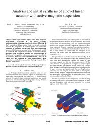
<strong>Simulating</strong> <strong>EMC</strong>/<strong>EMI</strong> <strong>Effects</strong> <strong>for</strong><br />
<strong>High</strong> <strong>Power</strong> <strong>Inverter</strong> <strong>Systems</strong><br />
Emmanuel Batista<br />
Vincent Delafosse,<br />
Alstom Pearl<br />
Ryan Magargle Ansoft Corporation<br />
emmanuel.batista@transport.alstom.com<br />
vdelafosse@ansoft.com<br />
rmagargle@ansoft.com<br />
© 2008 Ansoft, LLC All rights reserved. Ansoft, LLC Proprietary
Acknowledgments<br />
This work has been based on the work of<br />
Emmanuel Batista, J.M. Dienot, M. Mermet-Guyennet<br />
Special Thanks:<br />
–<br />
–<br />
–<br />
P. Solomalala (Pearl/Alstom)<br />
O.Roll, X. Legoar, D. Prestaux,<br />
X. Wu, M. Rosu, S. Kher (Ansoft)<br />
© 2008 Ansoft, LLC All rights reserved. Ansoft, LLC Proprietary
Pearl: <strong>Power</strong> Electronics Associated Research Laboratory<br />
Research<br />
Viability<br />
and Validation of technologies Development<br />
and maintenance<br />
Passive Components<br />
Active Components<br />
Packaging<br />
and validation of prototypes<br />
Models-Simulation-Fabrication<br />
<strong>EMC</strong><br />
Solve multi-domain/temps/structure<br />
Design of methods <strong>for</strong> conception<br />
© 2008 Ansoft, LLC All rights reserved. Ansoft, LLC Proprietary
Motivation<br />
•<br />
•<br />
•<br />
•<br />
<strong>High</strong> power IGBT based inverter systems have specific <strong>EMC</strong>/<strong>EMI</strong><br />
requirements<br />
The prediction of <strong>EMC</strong>/<strong>EMI</strong> fields is very difficult . Physical prototyping<br />
can result in long design cycles<br />
Simulation tools can help with the use of several techniques<br />
The physical quantities in the inverter that need accurate simulation are:<br />
–<br />
–<br />
–<br />
–<br />
–<br />
Quantity of current going through the conductors<br />
Frequency dependent parasitics (RLC) between conductors<br />
IGBT characterization curves<br />
<strong>Power</strong> dissipation<br />
Emitted fields<br />
© 2008 Ansoft, LLC All rights reserved. Ansoft, LLC Proprietary
Overview<br />
•<br />
•<br />
•<br />
•<br />
•<br />
•<br />
Introduction to the power study<br />
Static electromagnetic field study<br />
Parasitics extraction<br />
IGBT characterization<br />
System simulation<br />
Emitted fields<br />
© 2008 Ansoft, LLC All rights reserved. Ansoft, LLC Proprietary
Introduction<br />
•<br />
These<br />
power converters<br />
Pantograph<br />
Traction Supply<br />
Traction<br />
Motor<br />
IGBT Module Top Row<br />
are used<br />
<strong>Inverter</strong><br />
in high<br />
© 2008 Ansoft, LLC All rights reserved. Ansoft, LLC Proprietary<br />
AM<br />
3~<br />
speed trains (TGV)<br />
<strong>Inverter</strong> Leg
Introduction<br />
Emitter<br />
Dielectric<br />
Gel<br />
Diode<br />
Chip<br />
IGBT<br />
Chips<br />
6.5kV IGBT Module Characteristics<br />
Baseplate<br />
Ceramic<br />
Substrate<br />
Collector<br />
Packaging<br />
6.5kV-600A<br />
6.5kV 600A<br />
Module<br />
24 IGBT and<br />
12 Diode Chips<br />
© 2008 Ansoft, LLC All rights reserved. Ansoft, LLC Proprietary
Introduction<br />
6.5kV IGBT Module Analysis<br />
© 2008 Ansoft, LLC All rights reserved. Ansoft, LLC Proprietary<br />
•<br />
•<br />
•<br />
•<br />
Include package in IGBT<br />
per<strong>for</strong>mance<br />
Find DC current distribution<br />
Find switching currents <strong>for</strong><br />
power dissipation<br />
Use power dissipation to<br />
determine environmental<br />
electromagnetic fields
Introduction<br />
IGBT Module<br />
Pack 3D<br />
accurate model<br />
Electromagnetic<br />
(EM) study<br />
Model design developed<br />
•<br />
Parameters<br />
Extraction<br />
© 2008 Ansoft, LLC All rights reserved. Ansoft, LLC Proprietary<br />
at<br />
Alstom/Pearl<br />
Design and Couplings<br />
Model<br />
IGBT Model<br />
Tridimensional IGBT pack model and EM study<br />
• Parasitic model extraction<br />
• IGBT circuit model<br />
• Far Field Study <strong>for</strong> Electric Field EM<br />
Far Field Study
Introduction<br />
Different<br />
Finite Element Method<br />
Modeling<br />
Boundary Element<br />
Method<br />
•<br />
techniques will<br />
© 2008 Ansoft, LLC All rights reserved. Ansoft, LLC Proprietary<br />
be<br />
seen<br />
Tridimensional IGBT pack model and EM study<br />
• Parasitic model extraction<br />
• IGBT circuit model<br />
System Simulation<br />
• Far Field Study <strong>for</strong> Electric Field EM<br />
Finite Element<br />
Method
Overview<br />
•<br />
•<br />
•<br />
•<br />
•<br />
•<br />
Introduction to the power study<br />
Static electromagnetic field study<br />
Parasitics extraction<br />
IGBT characterization<br />
System simulation<br />
Emitted fields<br />
© 2008 Ansoft, LLC All rights reserved. Ansoft, LLC Proprietary
ElectroMagnetic Study<br />
•<br />
•<br />
Module layout<br />
verification<br />
The module contains 8 IGBTs in parallel:<br />
does each IGBT receive the same amount of<br />
current?<br />
–<br />
–<br />
If the current flows un-evenly, this will cause<br />
mechanical stress and reliability issues.<br />
Electromagnetic simulation is required. We<br />
use Maxwell3D.<br />
© 2008 Ansoft, LLC All rights reserved. Ansoft, LLC Proprietary
ElectroMagnetic Study<br />
•<br />
•<br />
•<br />
•<br />
•<br />
The layout<br />
The DC solver<br />
in imported<br />
is<br />
The input current<br />
The sink<br />
used<br />
from<br />
(600 A) is<br />
(return current<br />
Outputs: conduction path<br />
path) is<br />
the CAD tool<br />
defined<br />
defined<br />
600 A Sink<br />
and current<br />
distribution<br />
© 2008 Ansoft, LLC All rights reserved. Ansoft, LLC Proprietary
ElectroMagnetic Study<br />
The structure is meshed<br />
using automatic and<br />
adaptive meshing<br />
Current Distribution<br />
IGBTs on, Diodes off<br />
© 2008 Ansoft, LLC All rights reserved. Ansoft, LLC Proprietary
ElectroMagnetic Study<br />
•<br />
•<br />
•<br />
The end IGBTs see less current<br />
than the center ones.<br />
This can cause reliability issues<br />
as the center IGBTs will be<br />
overloaded<br />
An optimization of the copper<br />
tracks can be made in order to<br />
equalize the currents.<br />
Igbt1a and Igbt4a have the<br />
highest quantity of current<br />
© 2008 Ansoft, LLC All rights reserved. Ansoft, LLC Proprietary
Overview<br />
•<br />
•<br />
•<br />
•<br />
•<br />
•<br />
Introduction to the power study<br />
Near field electromagnetic study<br />
Parasitics extraction<br />
IGBT characterization<br />
System simulation<br />
Emitted fields<br />
© 2008 Ansoft, LLC All rights reserved. Ansoft, LLC Proprietary
Parasitics Extraction<br />
•<br />
•<br />
•<br />
Once the layout is optimized, the next step is to extract the resistance,<br />
inductance and capacitance (RLC) parameters of the package.<br />
For this<br />
Example<br />
we<br />
use the boundary<br />
<strong>for</strong> two conductors<br />
element<br />
method<br />
in Q3D<br />
© 2008 Ansoft, LLC All rights reserved. Ansoft, LLC Proprietary
Parasitics Extraction<br />
•<br />
Frequency Dependent <strong>Effects</strong><br />
•<br />
•<br />
•<br />
Integrated power-electronic modules exhibit frequency-dependent<br />
behavior due to eddy current and skin effects.<br />
In these cases, it may not be sufficient to rely on resistance and<br />
inductance extracted at a single operating frequency<br />
For example, coax conductors:<br />
Low Frequency <strong>High</strong> Frequency<br />
Same<br />
geometry<br />
Different<br />
frequency<br />
© 2008 Ansoft, LLC All rights reserved. Ansoft, LLC Proprietary<br />
=<br />
Different Parasitics
Parasitics Extraction<br />
•<br />
Gate<br />
Extracting parameters is straight<strong>for</strong>ward as the nets are<br />
automatically assigned.<br />
net<br />
Emitter<br />
Collector net<br />
© 2008 Ansoft, LLC All rights reserved. Ansoft, LLC Proprietary<br />
net
Parasitics Extraction<br />
•<br />
•<br />
How do we set up the frequency sweep?<br />
–<br />
–<br />
We<br />
Through Nyquist sampling, we know that to capture a<br />
time step of Ts, we need to obtain frequency domain<br />
in<strong>for</strong>mation up to:<br />
1<br />
Fmax<br />
=<br />
2×<br />
t<br />
For a time domain wave<strong>for</strong>m with a risetime of 80 ns, in<br />
order to capture the ringing in the time domain, we would<br />
want to capture at least 4 samples during this risetime.<br />
This implies a sampling time of 20 ns<br />
need<br />
to solve<br />
s<br />
up to 50 MHz (= 1/20ns)<br />
© 2008 Ansoft, LLC All rights reserved. Ansoft, LLC Proprietary
Parasitics Extraction<br />
•<br />
The simulation outputs consist of the RLC matrices <strong>for</strong> different frequencies<br />
© 2008 Ansoft, LLC All rights reserved. Ansoft, LLC Proprietary
Parasitics Extraction<br />
•<br />
•<br />
How do we<br />
Basic methodology:<br />
•<br />
•<br />
•<br />
•<br />
use the parasitics in the circuit simulator?<br />
Compute N-port S parameters (frequency sweep)<br />
Convert this into in<strong>for</strong>mation that circuit simulator understands<br />
Circuit simulator per<strong>for</strong>ms inverse FFT to find impulse response<br />
n<br />
y(<br />
nΔt)<br />
≅ ∑ s((<br />
n − k)<br />
Δt)<br />
x(<br />
kΔt)<br />
k = n−(<br />
N −1)<br />
Convolution is used to produce time-domain results<br />
© 2008 Ansoft, LLC All rights reserved. Ansoft, LLC Proprietary<br />
t<br />
∫−∞ Y ( jω<br />
) = S(<br />
jω)<br />
X ( jω)<br />
→ y(<br />
t)<br />
= s(<br />
t)<br />
⊗ x(<br />
t)<br />
= s(<br />
t −τ<br />
) x(<br />
τ ) dτ<br />
Copper shield<br />
Silicon<br />
Polyethylene<br />
Silicon<br />
Copper<br />
Voltage<br />
1.1<br />
1.1<br />
1.1<br />
1.0<br />
950.0m<br />
900.0m<br />
876.5m<br />
Voltage versus Time Using Different 2D Extractor Mode<br />
Damping<br />
VM11.V [V]<br />
VM_Linear_1Hz_Model.V [V]<br />
VM_Linear_1MHz_Model.V [V]<br />
VM_Frequency_Model.V [V]<br />
Phase<br />
17.55u 18.00u 18.50u 19.00u 19.50u<br />
20.00u<br />
Time (Seconds)
Overview<br />
•<br />
•<br />
•<br />
•<br />
•<br />
•<br />
Introduction to the power study<br />
Near field electromagnetic study<br />
Parasitics extraction<br />
IGBT characterization<br />
System simulation<br />
Emitted fields<br />
© 2008 Ansoft, LLC All rights reserved. Ansoft, LLC Proprietary
SIMPLORER 8<br />
•<br />
•<br />
Simplorer 8 is a circuit simulation<br />
tool <strong>for</strong> solving multi-domain lumped<br />
circuit problems.<br />
Link projects together to achieve<br />
dynamic linking of multiple<br />
simulations on a single sheet.<br />
© 2008 Ansoft, LLC All rights reserved. Ansoft, LLC Proprietary
SIMPLORER 8<br />
•<br />
Modeling<br />
•<br />
•<br />
•<br />
•<br />
New Parametrization<br />
tool <strong>for</strong> IGBT<br />
Enhanced SMPS Library - Over<br />
450 New VHDL-AMS DC/DC<br />
Converter Models in SMPS Digital<br />
Co-simulation<br />
Spice–Pspiceintegration<br />
Enhancements to individual<br />
models …<br />
© 2008 Ansoft, LLC All rights reserved. Ansoft, LLC Proprietary
System Integration<br />
•<br />
How do we<br />
import the results<br />
from<br />
•<br />
•<br />
•<br />
•<br />
•<br />
Q3D?: Q3D dynamic link<br />
2 Types of links: Single Frequency or<br />
Frequency dependent<br />
No need<br />
to manually<br />
import output file<br />
Simplorer incorporates directly the Q3D<br />
project<br />
If some results are not available, Simplorer<br />
dynamically launches Q3D<br />
Parameters and variables can be passed<br />
between S8 and Q3D<br />
© 2008 Ansoft, LLC All rights reserved. Ansoft, LLC Proprietary
System Simulation<br />
Wattmeter<br />
IGBT<br />
Vc<br />
<strong>Power</strong> Module from Q3D<br />
<strong>for</strong> board parasitics<br />
© 2008 Ansoft, LLC All rights reserved. Ansoft, LLC Proprietary<br />
Vg
IGBT Characterization<br />
2 types of models<br />
•<br />
•<br />
•<br />
Basic Dynamic<br />
Accurate models of the semiconductors<br />
are needed to achieve a good circuit<br />
simulation<br />
Simplorer 8 offers a parameterization<br />
tool <strong>for</strong> IGBTs<br />
The user needs to import the data from<br />
the datasheet<br />
are available<br />
and Average Dynamic<br />
in Simplorer 8:<br />
© 2008 Ansoft, LLC All rights reserved. Ansoft, LLC Proprietary
IGBT Characterization<br />
Objective Average Basic<br />
Dynamic<br />
DC<br />
characteristics<br />
Electrical<br />
Dynamics<br />
Thermal<br />
Dynamics<br />
Capacitance<br />
Models<br />
-<br />
Transfer characteristic<br />
Advanced Dynamic<br />
Ic(Vge) accurate<br />
- Output characteristic Ic(Vce) accurate in<br />
the regions of voltage and current saturation<br />
- Intrinsic temperature dependency<br />
-<br />
Considered<br />
Partial Fractional or<br />
Continued Fractional<br />
- Default Full access to the<br />
C(V) C(V) characteristics<br />
© 2008 Ansoft, LLC All rights reserved. Ansoft, LLC Proprietary
IGBT Characterization<br />
Sub circuit of the basic dynamic IGBT model<br />
© 2008 Ansoft, LLC All rights reserved. Ansoft, LLC Proprietary
IGBT Characterization<br />
SheetScan<br />
© 2008 Ansoft, LLC All rights reserved. Ansoft, LLC Proprietary
IGBT Characterization<br />
•<br />
•<br />
Once all the curves<br />
The tool<br />
fits<br />
and data are entered, start<br />
the data to the internal<br />
Characterization tool<br />
extraction<br />
Simplorer model using<br />
Genetic<br />
Algorithm<br />
Component dialog<br />
© 2008 Ansoft, LLC All rights reserved. Ansoft, LLC Proprietary
IGBT Characterization<br />
Test Circuit<br />
rise time= 40 μs<br />
fall time = 50 μs<br />
Ansoft Corporation Simplorer1<br />
50.00 3000.00<br />
15.00<br />
R2.I [A]<br />
40.00<br />
30.00<br />
20.00<br />
10.00<br />
0.00<br />
-10.00<br />
U1.VCE<br />
2500.00<br />
2000.00<br />
1500.00<br />
1000.00<br />
500.00<br />
0.00<br />
499.90 499.95 500.00 500.05 500.10<br />
Time [us]<br />
500.15 500.20 500.25 500.30<br />
2000.00<br />
1500.00<br />
1000.00<br />
500.00<br />
© 2008 Ansoft, LLC All rights reserved. Ansoft, LLC Proprietary<br />
switch_on<br />
TR<br />
TR<br />
TR<br />
Curve Info<br />
Ansoft Corporation Simplorer1<br />
50.00 2500.00<br />
15.00<br />
Curve Info<br />
R2.I [A]<br />
40.00<br />
30.00<br />
20.00<br />
10.00<br />
0.00<br />
-10.00<br />
U1.VCE<br />
Vce<br />
Switch on<br />
Switch off<br />
switch_off<br />
Ic<br />
Vce<br />
0.00<br />
-15.00<br />
999.00 999.50 1000.00 1000.50 1001.00<br />
Time [us]<br />
1001.50 1002.00 1002.50 1003.00<br />
Ic<br />
U1.VCE<br />
VM2.V<br />
R2.I<br />
TR<br />
5.00<br />
0.00<br />
-5.00<br />
10.00<br />
5.00<br />
0.00<br />
-10.00<br />
-5.00<br />
-10.00<br />
-15.00<br />
U1.VCE<br />
VM2.V<br />
TR 10.00<br />
TR<br />
R2.I<br />
VM2.V [V]<br />
VM2.V [V]
System Simulation<br />
2500 Voltage<br />
Source<br />
Line Resistance<br />
and Line Inductance<br />
Vg: Gate Voltage<br />
(+/-15V)<br />
© 2008 Ansoft, LLC All rights reserved. Ansoft, LLC Proprietary
System Simulation<br />
•<br />
•<br />
•<br />
Issue:<br />
•<br />
•<br />
Accurate simulation of the switching of the IGBTS requires<br />
very small time steps (hmin = 10ps)<br />
System simulation requires<br />
long time step<br />
(t = 5ms)<br />
Simplorer allows the user to dynamically change hmin and hmax<br />
using State Graphs.<br />
When<br />
the switching<br />
has occured, the time step<br />
© 2008 Ansoft, LLC All rights reserved. Ansoft, LLC Proprietary<br />
can<br />
be<br />
increased.<br />
Switching Steady state Switching
System Simulation<br />
-Vge<br />
Vce<br />
Vge<br />
Vce<br />
Ic<br />
Reduce Time Step HMin<br />
Ic<br />
Vge<br />
Vce<br />
Vce, Vge, Ic<br />
over time (Igbt3b)<br />
© 2008 Ansoft, LLC All rights reserved. Ansoft, LLC Proprietary<br />
Vge<br />
Vce<br />
Ic<br />
Vge<br />
Ic<br />
g<br />
Vce<br />
c<br />
e<br />
Ic
System Simulation<br />
Vg<br />
Vce<br />
Vge<br />
<strong>Power</strong><br />
The power pulse duration is much smaller than the rise/fall time<br />
© 2008 Ansoft, LLC All rights reserved. Ansoft, LLC Proprietary<br />
Ic<br />
of Ic<br />
and Vce
System Simulation<br />
Instantaneous power level through Igbt3a<br />
© 2008 Ansoft, LLC All rights reserved. Ansoft, LLC Proprietary
System Simulation<br />
<strong>Power</strong> levels of the full set of IGBT’s on switch on<br />
© 2008 Ansoft, LLC All rights reserved. Ansoft, LLC Proprietary
System Simulation<br />
•<br />
•<br />
Igbt1a and Igbt4a receive the highest<br />
power levels.<br />
This is consistent with the DC<br />
Conduction Maxwell3D solution<br />
Igbt1a<br />
Igbt4a<br />
© 2008 Ansoft, LLC All rights reserved. Ansoft, LLC Proprietary
System Simulation<br />
The fundamental frequencies of the power range<br />
between 16 and 54 MHz<br />
t @<br />
Pmax<br />
(μs)<br />
t @ P<br />
System Simulation<br />
FTT of the power through Igbt1a<br />
Most of the power level is below 110 MHz<br />
© 2008 Ansoft, LLC All rights reserved. Ansoft, LLC Proprietary
Emitted Fields<br />
•<br />
•<br />
There is very high power going through the IGBTs (almost 60 000 W in this<br />
study) during a very short period of time (60 ns). This switching can cause<br />
<strong>EMI</strong> issues in the inverter, but also in the surrounding equipment<br />
To be<br />
•<br />
•<br />
answered<br />
using<br />
the finite<br />
Will the module radiate?<br />
Are the field<br />
levels<br />
surrounding<br />
element<br />
method<br />
the module within<br />
in HFSS:<br />
mandated levels?<br />
© 2008 Ansoft, LLC All rights reserved. Ansoft, LLC Proprietary
Emitted Fields<br />
•<br />
•<br />
•<br />
•<br />
•<br />
The power pulse in the IGBTs have most of the<br />
energy in the 16- 110 MHz range.<br />
The largest<br />
There is<br />
metallic<br />
piece<br />
is<br />
a chance of having<br />
λ<br />
< 4 * L = 600 mm.<br />
This is<br />
By itself, the module will<br />
150 mm in the module<br />
radiation if<br />
<strong>for</strong> a frequency<br />
not radiate.<br />
of 500 MHz.<br />
However, the power module in the train is<br />
surrounded by other metallic objects than can be<br />
fairly large. These objects can cause the radiation<br />
of electric fields during switching.<br />
Maxwell’s Equations<br />
div D = ρ<br />
curl E = -∂B/∂t<br />
div B = 0<br />
curl H = J + ∂D/∂t<br />
© 2008 Ansoft, LLC All rights reserved. Ansoft, LLC Proprietary
Emitted Fields<br />
Exposure<br />
limits<br />
defined<br />
by European<br />
Community<br />
© 2008 Ansoft, LLC All rights reserved. Ansoft, LLC Proprietary<br />
•<br />
•<br />
Regulators impose<br />
maximum levels of<br />
electric fields close to<br />
electric equipment.<br />
In the 10-110 MHz<br />
range:<br />
Emax=61V/m
Emitted Fields<br />
•<br />
•<br />
Each<br />
IGBT pad is<br />
The port lies between<br />
excited<br />
using<br />
the collector<br />
lumped<br />
ports<br />
and emitter pads<br />
© 2008 Ansoft, LLC All rights reserved. Ansoft, LLC Proprietary
Emitted Fields<br />
•<br />
•<br />
The structure is discretized with adaptive meshing. The meshing<br />
frequency is 100 MHz<br />
The frequency<br />
sweep<br />
ranges from 15MHz to 120 MHz<br />
© 2008 Ansoft, LLC All rights reserved. Ansoft, LLC Proprietary
Emitted Fields<br />
Spectrum<br />
(MHz)<br />
For each<br />
<strong>Power</strong><br />
(W)<br />
frequency, the power amplitude is<br />
E field at 1m <strong>for</strong> 1000w<br />
(V/m)<br />
E field at 1m<br />
(V/m)<br />
16.52892562 21439.97604 2.6312 56.41286497<br />
33.05785124 8635.09049 2.7994 24.17307232<br />
49.58677686 5579.619715 2.8731 16.0308054<br />
66.11570248 4131.16773 3.063 12.65376676<br />
82.6446281 3276.823585 3.4045 11.15594589<br />
99.17355372 2712.888158 3.8924 10.55964586<br />
115.7024793 2308.359536 4.4861 10.35553171<br />
132.231405 2022.75744 4.905 9.921625241<br />
Spectrum from<br />
Outputs from Simplorer<br />
Inputs <strong>for</strong> HFSS<br />
Simplorer<br />
Outputs From HFSS<br />
(normalized results)<br />
Fields Levels<br />
entered<br />
© 2008 Ansoft, LLC All rights reserved. Ansoft, LLC Proprietary
Emitted Fields<br />
mag<br />
E @ 100 MHz, <strong>Power</strong> = 10 000W<br />
© 2008 Ansoft, LLC All rights reserved. Ansoft, LLC Proprietary<br />
•<br />
•<br />
•<br />
The E field is very localized<br />
close to the module even at<br />
100 MHz<br />
However, the very high<br />
power can lead to large<br />
values of E field even far<br />
from the module<br />
This design is fine at<br />
110MHz.<br />
<strong>Power</strong> E field at 1m<br />
Spectrum (M Hz) (W) (V/ m)<br />
115.7024793 2308.359536 10.35553171
Conclusion<br />
•<br />
•<br />
•<br />
•<br />
We have seen that the combination of several simulation techniques can<br />
give a good approach to <strong>EMC</strong>/<strong>EMI</strong> issues, both in conduction and emission<br />
modes<br />
Accurate prediction requires the use of Finite Element Methods, Boundary<br />
Element Methods, System Simulation along with Accurate Component<br />
Characteristics<br />
Package traces need optimization to balance current distribution<br />
The simulated module does not radiate <strong>for</strong> the given harmonics, and is<br />
within regulated near field field limits.<br />
© 2008 Ansoft, LLC All rights reserved. Ansoft, LLC Proprietary