installation, operating and service instructions evca series ...
installation, operating and service instructions evca series ... installation, operating and service instructions evca series ...
Figure 5: Horizontal Air Intake Piping Figure 6: Vertical Air Intake Piping 16
C. WATER TREATMENT The quality of water used in the heating system is essential for the successful operation and longevity of the system components. A successful water treatment plan will help to maintain efficiency, reduce the regularity of repair and/ or replacement, and extend the working life of the boiler and other system equipment. If left untreated, poor water quality could cause a number of problems including, but not limited to, oxidation, scaling, corrosion, and fouling. See Table 1A for examples of typical chemical agents found in untreated water along with their potential effects. Table 1A: Chemical Agents and Effects Compound Calcium Carbonate (CaCO 3 ) Calcium Bicarbonate (CaHCO 3 ) Calcium Sulphate (CaSO 4 ) Calcium Chloride (CaCl 2 ) Magnesium Carbonate (MgCO 3 ) Magnesium Bicarbonate (MgHCO 3 ) Magnesium Sulphate (MgSO 4 ) Silicon Dioxide (SiO 2 ) Effect Soft Scale Soft Scale, CO 2 Hard Scale Corrosion Soft Scale Corrosion, Scale Corrosion Hard Scale CAUTION The water shall have a maximum water hardness of 8.5 grains or 150 ppm. The recommended pH range is 8.8 to 9.2. However, other aspects of water quality can affect boiler operation and longevity. A qualified water treatment expert should be consulted to develop a complete water treatment plan. Oxygen contamination of boiler water will cause corrosion of iron and steel boiler components, and can lead to boiler failure. Thermal Solutions Standard Warranty does not cover problems caused by oxygen contamination of boiler water. Proper water treatment and boiler maintenance is required to avoid scale build-up on the inside of the boiler. Thermal Solutions Standard Warranty does not cover problems caused by scale build-up. When using Glycol products, all Glycol manufacturers' requirements, including rust inhibitors, must be adhered. Max 50% Glycol. Since the condition of water varies from location to location, it is impossible to prescribe a one-size-fits-all treatment plan for the system water. In order to develop an effective water treatment plan, it will be necessary to gain knowledge of the impurities dissolved in the water. Once all the impurities are identified, the proper treatment plan can be established. Therefore, it will be essential to obtain the expertise of a qualified industrial water treatment professional for establishing a treatment plan. In addition, a periodic testing/sampling plan should be developed. The intent of the plan should be to: (1) ensure the protection of the boiler and system equipment, (2) prevent an unforeseen system failure, (3) provide information for use in addressing the water quality, and (4) to confirm the proper concentration of chemicals in use. 17
- Page 1 and 2: INSTALLATION, OPERATING AND SERVICE
- Page 3 and 4: WARNING This boiler requires regula
- Page 5 and 6: 31.0 [787.4] MOUNTED LOW WATER CUT-
- Page 7 and 8: 40.8 [1036.3] MOUNTED LOW WATER CUT
- Page 9 and 10: a. Direct communication with outdoo
- Page 11 and 12: ii. Minimum three (3) feet above an
- Page 13 and 14: Figure 2: Typical Sidewall Pressuri
- Page 15: B. COMBUSTION AIR - See Figures 5 a
- Page 19 and 20: Figure 8: Schematic Boiler Piping 1
- Page 21 and 22: E. GAS PIPING WARNING Failure to pr
- Page 23 and 24: Pipe Size 1/2" 3/4" 1" 1-1/4" 1-1/2
- Page 25 and 26: Figure 9a: 208/230/480V - 1PH/3PH -
- Page 27 and 28: 27 Figure 9c: Control Wiring Schema
- Page 29 and 30: 29 Figure 9e: Control Wiring Schema
- Page 31 and 32: G. MODULAR SYSTEMS 1. General Guide
- Page 33 and 34: 33 Figure 11: Modular System Vertic
- Page 35 and 36: 35 Figure 13: Modular System: Typic
- Page 37 and 38: 37 Figure 15: Modular System: Typic
- Page 39 and 40: 39 Figure 17: Modular System: Typic
- Page 41 and 42: IV: System Start-up CAUTION Failure
- Page 43 and 44: WARNING Failure to properly adjust
- Page 45 and 46: 19. Reset the burner control by pre
- Page 47 and 48: Product Features Boiler Sequence (C
- Page 49 and 50: A. SAFETY AND OPERATING CONTROLS. O
- Page 51 and 52: TROUBLESHOOTING GUIDE (CONTINUED) L
- Page 53 and 54: D. INSPECTION AND CLEANING PROCEDUR
- Page 55 and 56: 2 1 Figure 18: Cleaning Secondary H
- Page 57 and 58: Figure 19: Boiler Combustion Chambe
- Page 59 and 60: TOP VIEW FRONT VIEW Figure 20: Burn
- Page 61 and 62: Figure 21a: UL/FM/CSD-1 Main Gas Tr
- Page 63 and 64: Figure 21b: UL/FM/CSD-1 Main Gas Tr
- Page 65 and 66: Figure 22a: DB&B Gas Train (750) Fi
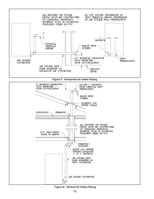
Figure 5: Horizontal Air Intake Piping<br />
Figure 6: Vertical Air Intake Piping<br />
16


