installation, operating and service instructions evca series ...
installation, operating and service instructions evca series ... installation, operating and service instructions evca series ...
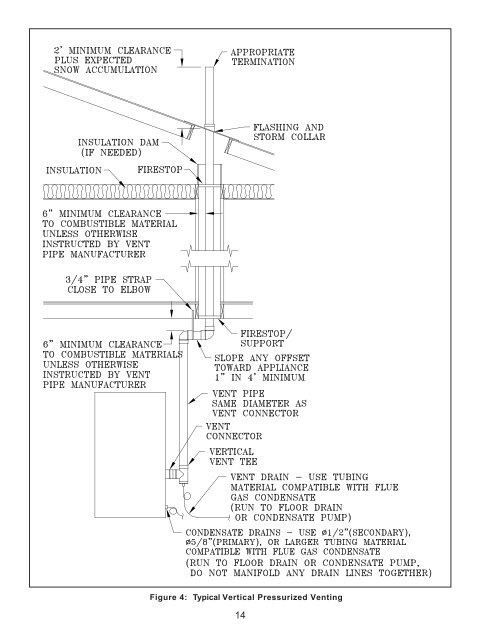
Figure 4: Typical Vertical Pressurized Venting 14
B. COMBUSTION AIR - See Figures 5 and 6 1. The boiler may be operated with inside or outside air. 2. Refer to combustion air piping drawings in this section of this manual for proper outside air installation details. 3. Combustion air conduit can be galvanized smoke pipe, PVC, CPVC, or flexible aluminum conduit. 4. The maximum air inlet length is fifty (50) equivalent feet. Air inlet length is equal to the total length of straight pipe plus the equivalent length of fittings. Consult conduit manufacturer for equivalent length of fittings and pipe. 5. Consult intake pipe manufacturer's instructions for proper method of sealing vent pipe sections and fittings. Do not use other adhesives or sealants except as expressly permitted by the vent pipe manufacturer's instructions. WARNING Do not locate air intake where petroleum distillates, CFCs, detergents, volatile vapors or any other chemicals are present. Severe boiler corrosion and failure will result. Thermal Solutions does not warrant failures caused by contaminated air. Do not locate air intake termination where natural convection or wind conditions may cause the boiler exhaust gases to be drawn into the air intake. WARNING Do not reduce size of air intake pipe. Read, understand and follow combustion air instruction restrictions contained in the Pre- Installation instructions of this manual. 6. Air intake termination must be located at least twelve (12) inches above grade plus the expected snow accumulation. 7. Boiler may be installed with vertical venting and sidewall combustion air inlet or visa versa. 8. The air intake pipe must be adequately supported with straps or supports no less than five (5) feet apart. The completed air intake pipe system must be rigid and able to withstand impacts without collapse. CAUTION Dirty, contaminated or dusty air used for combustion will decrease the useful life of the boiler air filter. Use outside air if inside air quality is questionable. Use outside air if the boiler is installed in manufacturing plants, laundries, dry cleaners or other locations with heavy particulates in the air. 15
- Page 1 and 2: INSTALLATION, OPERATING AND SERVICE
- Page 3 and 4: WARNING This boiler requires regula
- Page 5 and 6: 31.0 [787.4] MOUNTED LOW WATER CUT-
- Page 7 and 8: 40.8 [1036.3] MOUNTED LOW WATER CUT
- Page 9 and 10: a. Direct communication with outdoo
- Page 11 and 12: ii. Minimum three (3) feet above an
- Page 13: Figure 2: Typical Sidewall Pressuri
- Page 17 and 18: C. WATER TREATMENT The quality of w
- Page 19 and 20: Figure 8: Schematic Boiler Piping 1
- Page 21 and 22: E. GAS PIPING WARNING Failure to pr
- Page 23 and 24: Pipe Size 1/2" 3/4" 1" 1-1/4" 1-1/2
- Page 25 and 26: Figure 9a: 208/230/480V - 1PH/3PH -
- Page 27 and 28: 27 Figure 9c: Control Wiring Schema
- Page 29 and 30: 29 Figure 9e: Control Wiring Schema
- Page 31 and 32: G. MODULAR SYSTEMS 1. General Guide
- Page 33 and 34: 33 Figure 11: Modular System Vertic
- Page 35 and 36: 35 Figure 13: Modular System: Typic
- Page 37 and 38: 37 Figure 15: Modular System: Typic
- Page 39 and 40: 39 Figure 17: Modular System: Typic
- Page 41 and 42: IV: System Start-up CAUTION Failure
- Page 43 and 44: WARNING Failure to properly adjust
- Page 45 and 46: 19. Reset the burner control by pre
- Page 47 and 48: Product Features Boiler Sequence (C
- Page 49 and 50: A. SAFETY AND OPERATING CONTROLS. O
- Page 51 and 52: TROUBLESHOOTING GUIDE (CONTINUED) L
- Page 53 and 54: D. INSPECTION AND CLEANING PROCEDUR
- Page 55 and 56: 2 1 Figure 18: Cleaning Secondary H
- Page 57 and 58: Figure 19: Boiler Combustion Chambe
- Page 59 and 60: TOP VIEW FRONT VIEW Figure 20: Burn
- Page 61 and 62: Figure 21a: UL/FM/CSD-1 Main Gas Tr
- Page 63 and 64: Figure 21b: UL/FM/CSD-1 Main Gas Tr
Figure 4: Typical Vertical Pressurized Venting<br />
14


