installation, operating and service instructions eva series boiler
installation, operating and service instructions eva series boiler installation, operating and service instructions eva series boiler
DB&B AND IRI W/POC (Modulating) - MAIN AND PILOT Key No. Description 3. Main and Pilot Gas Train 3A 3B 3C 3D Main Gas 1" NPT Valve Body Main Gas Valve 1-1/2" NPT Main Gas 2" NPT Body, DBL Valve Body, DBL Manual Gas Valve Tapping, 1" NPT with Pilot Manual Gas Valve with Pilot Tapping, 1-1/2" NPT Manual Gas Valve Tapping, 2" NPT with Pilot DB&B Actuator/Regulator Ratio Valve Siemens SKP70 (max 5psi) IRI w/POC Actuator/Regulator Ratio ValveSiemens SKP70 (max 5psi) DB&B Actuator Siemens SKP10 IRI w/POC Actuator SKP10 3 E Manual Gas Cock 1/4" Siemens 3F 325-3 Pilot Gas Regulator 3G High Gas Pressure Switch 3H Low Gas Pressure Switch 3I Normally Open Vent Valve (Quantity) Part Number EVA-250 EVA-500 EVA-750 EVA-1000 EVA-1500 EVA-2000 (2) 816634041 — — — EVA-2000S EVA-2500 EVA-3000 — — — — — — (1) 81663405 — — — — — — — (2) 806603055 — — — — — (1) 816634051 — — — — — — (2) 806603053 — — — — — — — (1) 81663408 (1) 81663409 (1) 81663406 (1) 81663407 (3) 822758 (1) 822702 (1) 80160333 (1) 80160332 (1) 81660262 — — (1) 806604691 65
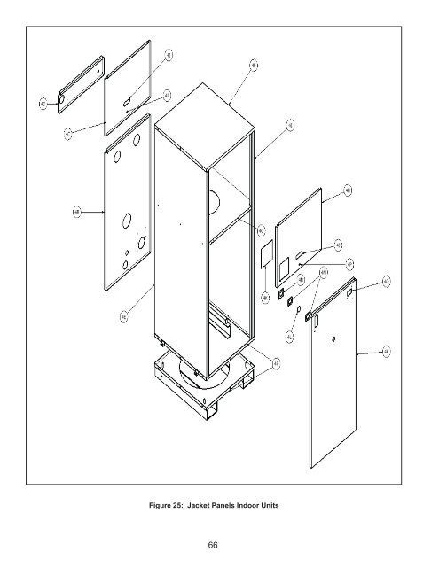
Figure 25: Jacket Panels Indoor Units 66
- Page 15 and 16: Figure 7: Vertical Air Intake Pipin
- Page 17 and 18: BOILER MODEL TABLE 1 - EVA BOILER F
- Page 19 and 20: D. GAS PIPING WARNING Failure to pr
- Page 21 and 22: TABLE 6 - EQUIVALENT OF STANDARD PI
- Page 23 and 24: Figure 9a: Standard UL/FM/CSD-1 Wir
- Page 25 and 26: Figure 9c: Standard UL/FM/CSD-1 Wir
- Page 27 and 28: CAUTION Installing multiple vent te
- Page 29 and 30: 28 Figure 12: Modular System Vertic
- Page 31 and 32: 30 Figure 14: Modular System: Typ P
- Page 33 and 34: 32 Figure 16: Modular System: Typ R
- Page 35 and 36: 34 Figure 18: Modular System: Typ P
- Page 37 and 38: IV. System Start-up CAUTION Failure
- Page 39 and 40: EE. Verify that all safety and oper
- Page 41 and 42: DANGER This boiler requires periodi
- Page 43 and 44: 42 VI. Service DANGER water hot ver
- Page 45 and 46: Troubleshooting Guide 44
- Page 47 and 48: NORMAL SEQUENCE OF OPERATION Boiler
- Page 49 and 50: Air Filter: A. Perform a visual ins
- Page 51 and 52: Figure 19: Combustion Chamber Assem
- Page 53 and 54: Figure 20: Burner Assembly 52
- Page 55 and 56: Figure 21a: UL/FM/CSD-1 Main Gas Tr
- Page 57 and 58: Figure 21b: UL/FM/CSD-1 Main Gas Tr
- Page 59 and 60: Figure 21c: UL/FM/CSD-1 Main Gas Tr
- Page 61 and 62: Figure 22a: DB&B/IRI w/POC Gas Trai
- Page 63 and 64: Figure 23a: DB&B/IRI w/POC Gas Trai
- Page 65: Figure 24a: DB&B/IRI w/POC Gas Trai
- Page 69 and 70: Figure 26a: Control Panel Assembly
- Page 71 and 72: Figure 26b: Control Panel Assembly
- Page 73 and 74: Figure 26c: Control Panel Assembly
- Page 75 and 76: Figure 27a: ULX2 Pilot Assembly 74
- Page 77 and 78: Figure 27b: "Bishop" Pilot Assembly
- Page 79 and 80: VIII Appendix A -Temperature Contro
- Page 81 and 82: NOTES 80
- Page 83: Thermal Solutions ("seller") LIMITE
Figure 25: Jacket Panels Indoor Units<br />
66


