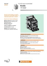
0Medium voltage circuit breaker
0Medium voltage circuit breaker
0Medium voltage circuit breaker

Create successful ePaper yourself
Turn your PDF publications into a flip-book with our unique Google optimized e-Paper software.
Switchgear<br />
definition<br />
<strong>0Medium</strong> <strong>voltage</strong> <strong>circuit</strong> <strong>breaker</strong><br />
IEC 60 056 and ANSI C37-06<br />
define on one hand the operating conditions,<br />
the rated characteristics, the design and<br />
the manufacture; and on the other hand<br />
the testing, the selection of controls<br />
and installation.<br />
Introduction<br />
# The <strong>circuit</strong> <strong>breaker</strong> is a device that ensures the control and protection<br />
on a network. It is capable of making, withstanding and interrupting<br />
operating currents as well as short-<strong>circuit</strong> currents.<br />
# The main <strong>circuit</strong> must be able to withstand without damage:<br />
5 the thermal current = short-<strong>circuit</strong> current during 1 or 3 s<br />
5 the electrodynamic current:<br />
2.5 • Isc for 50 Hz (IEC)<br />
2.6 • Isc for 60 Hz (IEC)<br />
2.7 • Isc (ANSI), for a particular time constant (IEC)<br />
5 the constant load current.<br />
# Since a <strong>circuit</strong> <strong>breaker</strong> is mostly in the "closed" position, the load<br />
current must pass through it without the temperature running away<br />
throughout the equipment's life.<br />
Characteristics<br />
Compulsory rated characteristics<br />
# Rated <strong>voltage</strong><br />
# Rated insulation level<br />
# Rated normal current<br />
# Rated short-time withstand current<br />
# Rated peak withstand current<br />
# Rated short-<strong>circuit</strong> duration<br />
# Rated supply <strong>voltage</strong> for opening and closing devices<br />
and auxiliary <strong>circuit</strong>s<br />
# Rated frequency<br />
# Rated short-<strong>circuit</strong> breaking current<br />
# Rated transient recovery <strong>voltage</strong><br />
# Rated short-<strong>circuit</strong> making current<br />
# Rated operating sequence<br />
# Rated time quantities.<br />
Special rated characteristics<br />
# These characteristics are not compulsory but can be requested for<br />
specific applications:<br />
5 rated out-of-phase breaking current,<br />
5 rated cable-charging breaking current,<br />
5 rated line-charging breaking current,<br />
5 rated capacitor bank breaking current,<br />
5 rated back-to-back capacitor bank breaking current,<br />
5 rated capacitor bank inrush making current,<br />
5 rated small inductive breaking current.<br />
Rated <strong>voltage</strong> (cf. § 4.1 IEC 60 694)<br />
The rated <strong>voltage</strong> is the maximum rms. value of the <strong>voltage</strong> that the<br />
equipment can withstand in normal service. It is always greater than the<br />
operating <strong>voltage</strong>.<br />
# Standardised values for Ur (kV) : 3.6 - 7.2 -12 - 17.5 - 24 - 36 kV.<br />
Schneider Electric<br />
Gamme<br />
AMTED300014EN_045_05
Switchgear<br />
definition<br />
<strong>0Medium</strong> <strong>voltage</strong> <strong>circuit</strong> <strong>breaker</strong><br />
100<br />
90<br />
50<br />
10<br />
Upeak (%)<br />
Rated insulation level<br />
(cf. § 4.2 IEC 60 056 and 60 694)<br />
# The insulation level is characterised by two values:<br />
5 the impulse wave withstand (1.2/50 µs)<br />
5 the power frequency withstand <strong>voltage</strong> for 1 minute.<br />
standardised wave<br />
Rated <strong>voltage</strong> Impulse withstand<br />
<strong>voltage</strong><br />
Power frequency<br />
withstand <strong>voltage</strong><br />
(Ur in kV) (Up in kV) (Ud in kV)<br />
7.2 60 20<br />
12 75 28<br />
17.5 95 38<br />
24 125 50<br />
36 170 70<br />
Rated normal current (cf. § 4.4 IEC 60 694)<br />
With the <strong>circuit</strong> <strong>breaker</strong> always closed, the load current must pass through<br />
it in compliance with a maximum temperature value as a function of the<br />
materials and the type of connections.<br />
IEC sets the maximum permissible temperature rise of various materials<br />
used for an ambient air temperature of no greater than 40°C<br />
(cf. § 4.4.2 table 3 IEC 60 694).<br />
Rated short-time withstand current<br />
(cf. § 4.5 IEC 60 694)<br />
Isc=<br />
Ssc<br />
----------------<br />
3 • U<br />
Ssc : short-<strong>circuit</strong> power (in MVA)<br />
U : operating <strong>voltage</strong> (in kV)<br />
Isc : short-<strong>circuit</strong> current (in kA)<br />
This is the standardised rms. value of the maximum permissible<br />
short-<strong>circuit</strong> current on a network for 1 or 3 seconds.<br />
# Values of rated breaking current under maximum short-<strong>circuit</strong> (kA):<br />
6.3 - 8 - 10 - 12.5 - 16 - 20 - 25 - 31.5 - 40 - 50 kA.<br />
Rated peak withstand current (cf. § 4.6 IEC 60 694)<br />
and making current (cf. § 4.103 IEC 60 056)<br />
The making current is the maximum value that a <strong>circuit</strong> <strong>breaker</strong> is capable<br />
of making and maintaining on an installation in short-<strong>circuit</strong>.<br />
It must be greater than or equal to the rated short-time withstand peak<br />
current.<br />
Isc is the maximum value of the rated short-<strong>circuit</strong> current for the <strong>circuit</strong><br />
<strong>breaker</strong>s’ rated <strong>voltage</strong>. The peak value of the short-time withstand<br />
current is equal to:<br />
2.5 • Isc for 50 Hz<br />
2.6 • Isc for 60 Hz<br />
2.7 • Isc for special applications.<br />
Rated short-<strong>circuit</strong> duration (cf. § 4.7 IEC 60 694)<br />
The rated short-<strong>circuit</strong> is equal to 1 or 3 seconds.<br />
TED300014EN_045_053.<br />
Gamme<br />
Schneider Electric
Switchgear<br />
definition<br />
<strong>0Medium</strong> <strong>voltage</strong> <strong>circuit</strong> <strong>breaker</strong><br />
Rated supply <strong>voltage</strong> for closing and opening<br />
devices and auxiliary <strong>circuit</strong>s (cf. § 4.8 IEC 60 694)<br />
# Values of supply <strong>voltage</strong> for auxiliary <strong>circuit</strong>s:<br />
5 for direct current (dc): 24 - 48 - 60 - 110 or 125 - 220 or 250 volts,<br />
5 for alternating current (ac): 120 - 220 - 230 - 240 volts.<br />
# The operating <strong>voltage</strong>s must lie within the following ranges:<br />
5 motor and closing release units:<br />
-15% to +10% of Ur in cc and ac<br />
5 opening release units:<br />
-30% to +10% of Ur in dc<br />
-15% to +10% of Ur in ac<br />
5 under<strong>voltage</strong> opening release unit:<br />
the release unit gives<br />
the command and<br />
fotbids closing<br />
the release unit<br />
must not have<br />
an action<br />
0 % 35 % 70 % 100 %<br />
(at 85%, the release unit must enable<br />
the device to close)<br />
U<br />
Rated frequency (cf. § 4.9 IEC 60 694)<br />
Two frequencies are currently used throughout the world:<br />
50 Hz in Europe and 60 Hz in America, a few countries use both<br />
frequencies. The rated frequency is either 50 Hz or 60 Hz.<br />
Isc<br />
Ir<br />
t<br />
O C O C O<br />
t'<br />
time<br />
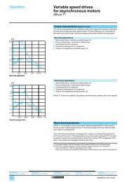
Rated operating sequence (cf. § 4.104 IEC 60 056)<br />
# Rated switching sequence according to IEC, O - t - CO - t’ - CO.<br />
(cf: opposite diagram)<br />
O : represents opening operation<br />
CO : represents closing operation<br />
followed immediately by an opening operation<br />
# Three rated operating sequences exist:<br />
5 slow: 0 - 3 mn - CO - 3 mn - CO<br />
5 quick 1: O - 0.3 s - CO - 3 mn - CO<br />
5 quick 2: O - 0.3 s - CO - 15 s - CO<br />
N.B.: other sequences can be requested.<br />
# Opening/closing cycle<br />
Assumption: O order as soon as the <strong>circuit</strong> <strong>breaker</strong> is closed.<br />
open<br />
position<br />
displacement of<br />
contacts<br />
current flows<br />
time<br />
opening-closing duration<br />
energising of<br />
closing <strong>circuit</strong><br />
making-breaking duration<br />
contacts are touching in all<br />
poles and order O<br />
current starts to flow in first pole<br />
final arc extinction in all poles<br />
separation of arcing contacts in all poles<br />
Schneider Electric<br />
Gamme<br />
AMTED300014EN_045_05
Switchgear<br />
definition<br />
<strong>0Medium</strong> <strong>voltage</strong> <strong>circuit</strong> <strong>breaker</strong><br />
# Automatic reclosing cycle<br />
Assumption: C order as soon as the <strong>circuit</strong> <strong>breaker</strong> is open,<br />
(with time delay to achieve 0.3 sec or 15 secs or 3 min).<br />
closed position<br />
displacement of<br />
contacts<br />
open position<br />
current flows<br />
energisiong of<br />
opening release unit<br />
making-breaking duration<br />
opening-closing duration<br />
remaking duration<br />
reclosing duration<br />
final extinction in all poles<br />
separation of arc contacts in all<br />
poles and order C<br />
current flows<br />
temps<br />
the contacts are<br />
touching in all poles<br />
lthe contacts touch<br />
in the first pole<br />
start of current flow<br />
in the first pole<br />
Example 1 :<br />
# For a <strong>circuit</strong> <strong>breaker</strong> with a minimum<br />
opening duration of 45 ms (Top) to which<br />
we add 10 ms (Tr) due to relaying,<br />
the graph gives a percentage of the<br />
aperiodic component of around 30 %<br />
for a time constant τ1 = 45 ms:<br />
–( 45 + 10)<br />
--------------------------<br />
% DC = e 45 = 29.5%<br />
Example 2 :<br />
# Supposing that % DC of a MV<br />
<strong>circuit</strong> <strong>breaker</strong> is equal to 65% and that<br />
the symmetric short-<strong>circuit</strong> current that is<br />
calculated (Isym) is equal to 27 kA..<br />
What does Iasym equal?<br />
I asym = I sym 1 + 2 ----------------<br />
(%DC<br />
)<br />
100<br />
=<br />
27kA 1 + 2( 0.65) 2<br />
= 36.7 kA<br />
[A]<br />
# Using the equation [A],<br />
this is equivalent to a symmetric<br />
short-<strong>circuit</strong> current at a rating of:<br />
36· .7kA<br />
------------------ = 33.8kA<br />
1. ( 086)<br />
for a %DC of 30%.<br />
# The <strong>circuit</strong> <strong>breaker</strong> rating is greater<br />
than 33.8 kA. According to the IEC,<br />
the nearest standard rating is 40 kA.<br />
2<br />
}<br />
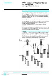
Rated short-<strong>circuit</strong> breaking current<br />
(cf. § 4.101 IEC 60 056)<br />
The rated short-<strong>circuit</strong> breaking current is the highest value of current that<br />
the <strong>circuit</strong> <strong>breaker</strong> must be capable of breaking at its rated <strong>voltage</strong>.<br />
# It is characterised by two values:<br />
5 the rms. value of its periodic component, given by the term:<br />
"rated short-<strong>circuit</strong> breaking current"<br />
5 the percentage of the aperiodic component corresponding to the <strong>circuit</strong><br />
<strong>breaker</strong>’s opening duration, to which we add a half-period of the rated<br />
frequency. The half-period corresponds to the minimum activation time of<br />
an overcurrent protection device, this being 10 ms at 50 Hz.<br />
# According to IEC, the <strong>circuit</strong> <strong>breaker</strong> must break the rms. value of the<br />
periodic component of the short-<strong>circuit</strong> (= its rated breaking current) with<br />
the percentage of asymmetry defined by the graphs below.<br />
Percentage of the aperiodic component (% DC) as a function of the time interval (τ)<br />
% DC<br />
00<br />
90<br />
80<br />
70<br />
60<br />
50<br />
40<br />
30<br />
20<br />
10<br />
(alternating time constant)<br />
(standardised time constant)<br />
0 10 20 30 40 50 60 70 80 90<br />
t : <strong>circuit</strong> <strong>breaker</strong> opening duration (Top), increased by half a period at the power frequency (τr).<br />
# As standard the IEC defines MV equipment for a %DC of 30%,<br />
for a peak value of maximum current equal to 2.5 • Isc at 50 Hz or<br />
2.6 • Isc at 60 Hz. In this case use the τ1 graph.<br />
TED300014EN_045_053.<br />
Gamme<br />
Schneider Electric
Switchgear<br />
definition<br />
<strong>0Medium</strong> <strong>voltage</strong> <strong>circuit</strong> <strong>breaker</strong><br />
# For low resistive <strong>circuit</strong>s such as generator incomers, %DC can be<br />
higher, with a peak value of maximum current equal to 2.7 • Isc.<br />
In this case use the τ4 graph.<br />
For all constants of between τ1 and τ4, use the equation:<br />
% DC=<br />
100 • e<br />
–( Top + Tr)<br />
---------------------------------<br />
τ1 , ...,<br />
4<br />
# Values of rated short-<strong>circuit</strong> breaking current:<br />
6.3 - 8 - 10 - 12,5 - 16 20 - 25 - 31.5 - 40 - 50 - 100 kA.<br />
I (A)<br />
IMC<br />
IAC<br />
t (s)<br />
# Short-<strong>circuit</strong> breaking tests must meet the five following test sequences:<br />
Séquence % Isym. % aperiodic<br />
component %DC<br />
1 10 ≤ 20<br />
2 20 ≤ 20<br />
3 60 ≤ 20<br />
4 100 ≤ 20<br />
5* 100 according to equation<br />
IDC<br />
* for <strong>circuit</strong> <strong>breaker</strong>s opening in less than 80 ms<br />
IMC<br />
IAC<br />
Idc<br />
%DC<br />
:<br />
:<br />
:<br />
:<br />
making current<br />
periodic component peak value (Isc peak)<br />
aperiodic component value<br />
% asymmetry or aperiodic component:<br />
IDC<br />
τ( 1 ,...,<br />
4)<br />
------- • 100 = 100 • e<br />
IAC<br />
–( Top + Tr)<br />
--------------------------------<br />
# Symmetric short-<strong>circuit</strong> current (in kA):<br />
Isym= IAC -------<br />
2<br />
# Asymmetric short-<strong>circuit</strong> current (in kA):<br />
Iasym 2 = I 2 AC + I 2 DC<br />
Iasym = Isym 1 2 ⎛ %DC<br />
⎝<br />
---------- ⎞ 2<br />
+<br />
100 ⎠<br />
Rated Transient Recovery Voltage (TRV)<br />
(cf. § 4.102 IEC 60 056)<br />
This is the <strong>voltage</strong> that appears across the terminals of a <strong>circuit</strong> <strong>breaker</strong><br />
pole after the current has been interrupted. The recovery <strong>voltage</strong> wave<br />
form varies according to the real <strong>circuit</strong> configuration.<br />
A <strong>circuit</strong> <strong>breaker</strong> must be able to break a given current for all recovery<br />
<strong>voltage</strong>s whose value remains less than the rated TRV.<br />
# First pole factor<br />
For three-phase <strong>circuit</strong>s, the TRV refers to the pole that breaks the <strong>circuit</strong><br />
initially, in other words the <strong>voltage</strong> across the terminals of the open pole.<br />
The ratio of this <strong>voltage</strong> to a simple <strong>voltage</strong> is called the first pole factor,<br />
it is equal to 1.5 for <strong>voltage</strong>s up to 72.5 kV.<br />
Schneider Electric<br />
Gamme<br />
AMTED300014EN_045_05
Switchgear<br />
definition<br />
<strong>0Medium</strong> <strong>voltage</strong> <strong>circuit</strong> <strong>breaker</strong><br />
# Value of rated TRV<br />
5 the TRV is a function of the asymmetry, it is given for an asymmetry of 0%.<br />
Uc<br />
U (kV)<br />
Rated TRV Time Delay Increase<br />
<strong>voltage</strong> value rate<br />
(Ur in kV) (Uc in kV) (t3 in µs) (td in µs) (Uc/td in kV/µs)<br />
7.2 12.3 52 8 0.24<br />
12 20.6 60 9 0.34<br />
17.5 30 72 11 0.42<br />
24 41 88 13 0.47<br />
36 62 108 16 0.57<br />
td<br />
0<br />
2<br />
Uc = 1.4 • 1.5 • ------ • Ur = 1.715Ur<br />
3<br />
t3<br />
td = 0.15t3<br />
5 a specified TRV is represented by a reference plot with two parameters<br />
and by a segment of straight line defining a time delay.<br />
Td : tme delay<br />
t3 : time defined to reach Uc<br />
Uc : peak TRV <strong>voltage</strong> in kV<br />
TRV increase rate:<br />
Uc/t3 in kV/µs<br />
X1<br />
A<br />
B<br />
X2<br />
Rated out-of-phase breaking current<br />
(cf. § 4.106 IEC 60 056)<br />
When a <strong>circuit</strong> <strong>breaker</strong> is open and the conductors are not synchronous,<br />
the <strong>voltage</strong> across the terminals can increase up the sum of <strong>voltage</strong>s in<br />
the conductors (phase opposition).<br />
G<br />
U1<br />
U2<br />
G<br />
# In practice, standards require the <strong>circuit</strong> <strong>breaker</strong> to break a current<br />
equal to 25% of the fault current across the terminals, at a <strong>voltage</strong><br />
equal to twice the <strong>voltage</strong> relative to earth.<br />
UA - UB = U1 - (-U2) = U1 + U2<br />
si U1 = U2 so UA - UB = 2U<br />
# If Ur is the rated <strong>circuit</strong> <strong>breaker</strong> <strong>voltage</strong>, the recovery <strong>voltage</strong> (TRV) at<br />
power frequency is equal to:<br />
5 2 Ur for networks with a neutral earthing arrangement<br />
5 2.5 Ur for other networks.<br />
# Peak values for TRV for networks other than those with neutral<br />
earthing:<br />
3<br />
Uc = 1.25 • 2.5 • ------ • Ur<br />
2<br />
Rated TRV Time Rate of<br />
<strong>voltage</strong> value increase<br />
(Ur in kV) (Uc in kV) (t3 in µs) (Uc/td in kV/µs)<br />
7.2 18.4 104 0.18<br />
12 30.6 120 0.26<br />
17.5 45 144 0.31<br />
24 61 176 0.35<br />
36 92 216 0.43<br />
TED300014EN_045_053.<br />
Gamme<br />
Schneider Electric
Switchgear<br />
definition<br />
<strong>0Medium</strong> <strong>voltage</strong> <strong>circuit</strong> <strong>breaker</strong><br />
Rated cable-charging breaking current<br />
(cf. § 4 .108 IEC 60 056)<br />
The specification of a rated breaking current for a <strong>circuit</strong> <strong>breaker</strong> located<br />
at the head of no-load cables is not compulsory and is considered as not<br />
being necessary for <strong>voltage</strong>s less than 24 kV.<br />
# Normal rated breaking current values for a <strong>circuit</strong> <strong>breaker</strong> located at the<br />
head of no-load cables:<br />
Rated <strong>voltage</strong> Rated breaking current<br />
for no-load cables<br />
(Ur in kV)<br />
(Ic in kA)<br />
7.2 10<br />
12 25<br />
17.5 31.5<br />
24 31.5<br />
36 50<br />
Rated line-charging breaking current<br />
(cf. § 4 .107 IEC 60 056)<br />
The specification of a rated breaking current for a <strong>circuit</strong> <strong>breaker</strong> switch<br />
situated at the head of no-load lines is limited to overhead, three-phased<br />
lines and to a rated <strong>voltage</strong> ≥ 72 kV.<br />
G<br />
U<br />
L<br />
A<br />
B<br />
Ic<br />
C<br />
Rated single capacitor bank breaking current<br />
(cf. § 4 .109 IEC 60 056)<br />
The specification of a breaking current for a <strong>circuit</strong> <strong>breaker</strong> switch located<br />
upstream of capacitors is not compulsory. Due to the presence of<br />
harmonics, the breaking current for capacitors is equal to 0.7 times the<br />
device’s rated current.<br />
Rated current Breaking current for capacitors<br />
(A)<br />
(A)<br />
400 280<br />
630 440<br />
1250 875<br />
2500 1750<br />
3150 2200<br />
By definition<br />
pu<br />
=<br />
Ur<br />
2<br />
------<br />
3<br />
# The normal value of over-<strong>voltage</strong> obtained is equal to 2.5 pu, this being:<br />
X1<br />
2<br />
2.5 • Ur ------<br />
3<br />
G<br />
U<br />
Rated back-to-back capacitor bank breaking current<br />
(cf. § 4.110 IEC 60 056)<br />
The specification of a breaking current for multi-stage capacitor banks is<br />
not compulsory.<br />
# If n is equal to the number of stages, then the over-<strong>voltage</strong> is equal to:<br />
C1 C2 C3<br />
2n<br />
2<br />
--------------- • pu with pu = Ur------<br />
2n + 1<br />
3<br />
Schneider Electric<br />
Gamme<br />
AMTED300014EN_045_05
Switchgear<br />
definition<br />
<strong>0Medium</strong> <strong>voltage</strong> <strong>circuit</strong> <strong>breaker</strong><br />
Rated capacitor bank inrush making current<br />
(cf. § 4.111 IEC 60 056)<br />
The rated closing current for capacitor banks is the peak current value<br />
that the <strong>circuit</strong> <strong>breaker</strong> must be capable of making at the rated <strong>voltage</strong>.<br />
The value of the <strong>circuit</strong> <strong>breaker</strong>’s rated closing current must be greater<br />
than the making current for the capacitor bank. In service, the frequency<br />
of the pick-up current is normally in the region of 2 - 5 kHz.<br />
Rated small inductive breaking current<br />
(cf. § 4.112 IEC 60 056)<br />
The breaking of a low inductive current (several amperes to several tens<br />
of amperes) causes over<strong>voltage</strong>s. The type of <strong>circuit</strong> <strong>breaker</strong> will be<br />
chosen so that the over<strong>voltage</strong>s that appear do not damage the insulation<br />
of the current consumers (transformer, motors).<br />
U<br />
Um<br />
Uf<br />
Uc<br />
Ud<br />
Up<br />
t<br />
# The figure opposite shows the various <strong>voltage</strong>s on the load side<br />
Uf : instantaneous network <strong>voltage</strong> value<br />
Uc : network <strong>voltage</strong> at the moment of breaking<br />
Um : extinction point<br />
Uif : over<strong>voltage</strong> relative to earth<br />
Up : maximum over<strong>voltage</strong> relative to earth<br />
Ud : maximum peak-to-peak amplitude of the over<strong>voltage</strong><br />
due to restrike.<br />
Uif<br />
# Insulation level of motors<br />
IEC 60 034 stipulates the insulation level of motors.<br />
Power frequency and impulse withstand testing is given in the table below<br />
(rated insulation levels for rotary sets).<br />
Insulation Test at 50 (60) Hz Impulse test<br />
rms. value<br />
Between turns<br />
(4 Ur + 5) kV<br />
4.9 pu + 5 = 31 kV at 6.6 kV<br />
(50% on the sample)<br />
increase time 0.5 µs<br />
Relative (2 Ur + 5) kV (4 Ur + 5) kV<br />
to earth 2Ur + 1 ⇒ 2(2Ur + 1) ⇒ 0 4.9 pu + 5 = 31 kV at 6.6 kV<br />
14 kV Ãê 28 kV ⇒ 0 increase time 1.2 µs<br />
1 kV/s<br />
t<br />
0<br />
1 mn<br />
Normal operating conditions (cf. IEC 60 694)<br />
For all equipment functioning under other conditions than those described<br />
below, derating should be carried out (see derating chapter). Equipment is<br />
designed for normal operation under the following conditions:<br />
# Temperature<br />
0°C Installation<br />
Instantaneous ambient Indoor Outdoor<br />
minimal -5°C -25°C<br />
maximal +40°C +40°C<br />
average daily maximum value 35°C 35°C<br />
TED300014EN_045_053.<br />
Gamme<br />
Schneider Electric
Switchgear<br />
definition<br />
<strong>0Medium</strong> <strong>voltage</strong> <strong>circuit</strong> <strong>breaker</strong><br />
# Humidity<br />
Average relative humidity<br />
Indoor equipment<br />
for a period<br />
24 hours 95 %<br />
1 month 90 %<br />
# Altitude<br />
The altitude must not exceed 1 000 metres.<br />
Electrical endurance<br />
The electrical endurance requested by the recommendation is three<br />
breaking operations at Isc.<br />
Merlin Gerin <strong>circuit</strong> <strong>breaker</strong>s are capable of breaking Isc at least 15 times.<br />
Mechanical endurance<br />
The mechanical endurance requested by the recommendation is 2 000<br />
switching operations.<br />
Merlin Gerin <strong>circuit</strong> <strong>breaker</strong>s guarantee 10 000 switching operations.<br />
Co-ordination of rated values (cf. § IEC 60 056)<br />
Rated Rated short-<strong>circuit</strong> Rated current in continuous service<br />
<strong>voltage</strong> breaking current<br />
Ur (kV) Isc (kV) Ir (A)<br />
3.6 10 400<br />
16 630 1250<br />
25 1250 1600 2500<br />
40 1250 1600 2500 3150<br />
7.2 8 400<br />
12.5 400 630 1250<br />
16 630 1250 1600<br />
25 630 1250 1600 2500<br />
40 1250 1600 2500 3150<br />
12 8 400<br />
12.5 400 630 1250<br />
16 630 1250 1600<br />
25 630 1250 1600 2500<br />
40 1250 1600 2500 3150<br />
50 1250 1600 2500 3150<br />
17.5 8 400 630 1250<br />
12.5 630 1250<br />
16 630 1250<br />
25 1250<br />
40 1250 1600 2500 3150<br />
24 8 400 630 1250<br />
12.5 630 1250<br />
16 630 1250<br />
25 1250 1600 2500<br />
40 1250 1600 2500 3150<br />
36 8 630<br />
12.5 630 1250<br />
16 630 1250 1600<br />
25 1250 1600 2500<br />
40 1250 1600 2500 3150<br />
Schneider Electric<br />
Gamme<br />
AMTED300014EN_045_05