

MEA0004 - Easel Assembly Instructions.pdf - Art to Art
MEA0004 - Easel Assembly Instructions.pdf - Art to Art
MEA0004 - Easel Assembly Instructions.pdf - Art to Art

You also want an ePaper? Increase the reach of your titles
YUMPU automatically turns print PDFs into web optimized ePapers that Google loves.
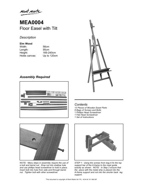
<strong>MEA0004</strong><br />
Floor <strong>Easel</strong> with Tilt<br />
Description<br />
Elm Wood<br />
Width:<br />
Length:<br />
Height:<br />
Holds canvas:<br />
56cm<br />
95cm<br />
165-240cm<br />
Up <strong>to</strong> 120cm<br />
<strong>Assembly</strong> Required<br />
Contents<br />
13 Pieces of Wooden <strong>Easel</strong> Parts<br />
8 Bags of Screws and Bolts<br />
1 Phillips Head Screwdriver<br />
1 Flat Head Screwdriver<br />
1 Set of <strong>Instructions</strong><br />
NOTE: Many steps in assembly require the use of<br />
a bolt and barrel nut. Drop nut in<strong>to</strong> shallow hole<br />
and use phillips head screwdriver <strong>to</strong> hold in place.<br />
Insert bolt in<strong>to</strong> hole from side and through barrel<br />
nut. Tighten bolt with other screwdriver.<br />
STEP 1: Using the screws from bag A fix the <strong>to</strong>p<br />
support bar of the A-frame <strong>to</strong> the mast guide<br />
exactly as shown. NOTE: In Step 2 ensure that<br />
the piece with the metal strip is placed in<strong>to</strong> the<br />
A-frame support and not in<strong>to</strong> the shorter back leg<br />
support.<br />
This document is copyright of Mont Marte Intl. P/L ACN 56 101 589 897
STEP 2: Connect piece from previous step <strong>to</strong> the<br />
piece with the metal strip and the bot<strong>to</strong>m of the<br />
A-frame support. These pieces slot <strong>to</strong>gether and<br />
no screwing is required. Ensure metal strip is<br />
placed so that it enters the bot<strong>to</strong>m of the A-Frame<br />
support bar.<br />
STEP 3: Attach side supports by slotting on<strong>to</strong><br />
piece from previous step. Ensure rounded ends of<br />
the side supports are at the <strong>to</strong>p. T urn A-frame<br />
over, drop in barrel nut and insert bolt from side<br />
and through barrel nut <strong>to</strong> secure.<br />
STEP 4: Attach the back support leg <strong>to</strong> A-frame<br />
using bolt and barrel nut from Bag C as shown.<br />
STEP 5: Using bolts and wing nuts from Bag D<br />
attach the 2 small thin pieces <strong>to</strong> the central<br />
column of the A-frame and the back support leg.<br />
Ensure washers are placed on the same side as<br />
the butterfly nuts.<br />
STEP 6: Slot easel mast in<strong>to</strong> <strong>to</strong>p of accessories<br />
tray. Turn piece over and drop in barrel nut.<br />
Insert bolt E1 through bot<strong>to</strong>m of tray and through<br />
barrel nut <strong>to</strong> secure.<br />
STEP 7: Screw “trigger” from bag E2 <strong>to</strong> base of<br />
accessories tray in<strong>to</strong> pre-drilled holes as shown.<br />
This document is copyright of Mont Marte Intl. P/L ACN 56 101 589 897
STEP 8: Slide easel mast with accesories tray<br />
attached through the mast guide.<br />
STEP 9: Pull trigger <strong>to</strong> allow tray <strong>to</strong> slide up, raise<br />
tray until the trigger can sit on the metal steps of<br />
central column. This is the easel height<br />
adjustment.<br />
NOTE: The next step requires attaching the small<br />
wooden “C” shape piece of wood. This piece has<br />
a wider cut out on one side. Ensure this piece is<br />
attached so that the wider cut out is placed<br />
<strong>to</strong>wards the <strong>to</strong>p. This will allow full tilt range.<br />
STEP 10: Fix small “C” shaped piece of wood<br />
over central A-frame column on<strong>to</strong> accessories tray<br />
with screws from Bag F as shown.<br />
STEP 11: Slide the <strong>to</strong>p canvas support on<strong>to</strong> the<br />
easel mast and use one of 2 remaining screws <strong>to</strong><br />
secure it in place.<br />
STEP 12: Screw remaining screw <strong>to</strong> the back of<br />
the mast guide. This allows adjustment of working<br />
angle. <strong>Easel</strong> is now ready for use!<br />
This document is copyright of Mont Marte Intl. P/L ACN 56 101 589 897
