Motorola ML12019 - Datasheet - Lansdale Semiconductor, Inc.
Motorola ML12019 - Datasheet - Lansdale Semiconductor, Inc.
Motorola ML12019 - Datasheet - Lansdale Semiconductor, Inc.

Create successful ePaper yourself
Turn your PDF publications into a flip-book with our unique Google optimized e-Paper software.
<strong>ML12019</strong><br />
Dual Modulus Prescaler<br />
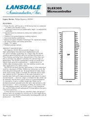
Legacy Device: <strong>Motorola</strong> MC12019<br />
MECL PLL COMPONENTS ÷20/21 DUAL MODULUS<br />
SEMICONDUCTOR TECHNICAL DATA<br />
The <strong>ML12019</strong> is a divide by 20 and 21 dual modulus<br />
prescaler. It will devide by 20 when the modulus control<br />
input is HIGH and divide by 21 when the modulus control<br />
input is LOW.<br />
• 225 MHz Toggle Frequency<br />
• Low–Power 7.5 mA Maximum at 5.5 V<br />
• Control Input is Compatible with Standard<br />
<strong>Motorola</strong> or <strong>Lansdale</strong> CMOS Synthesizers<br />
• Emitter Follower Output<br />
• Operating Temperature Range TA = –40 to 85°C<br />
P DIP 8 = PP<br />
PLASTIC PACKAGE<br />
CASE 626-04<br />
8<br />
1<br />
SO 8 = -5P<br />
PLASTIC PACKAGE<br />
CASE 751<br />
(SO–8)<br />
CROSS REFERENCE/ORDERING INFORMATION<br />
PACKAGE<br />
MOTOROLA<br />
LANSDALE<br />
P-DIP 8 MC12019P <strong>ML12019</strong>PP<br />
SO 8 MC12019D <strong>ML12019</strong>-5P<br />
Note: <strong>Lansdale</strong> lead free (Pb) product, as it<br />
becomes available, will be identified by a part<br />
number prefix change from ML to MLE.<br />
PIN CONNECTIONS<br />
SIMPLIFIED BLOCK DIAGRAM<br />
Control<br />
Input<br />
1<br />
IN<br />
NE<br />
Out<br />
Gnd<br />
1<br />
2<br />
3<br />
4<br />
8<br />
7<br />
6<br />
5<br />
(Top View)<br />
NC<br />
VCC<br />
SGnd<br />
SIN<br />
Signal<br />
Input<br />
Signal<br />
Gnd<br />
0.001 µF<br />
5<br />
6<br />
0.001 µF<br />
N / N+1<br />
3<br />
Output<br />
7<br />
0.1 µF<br />
VCC<br />
4<br />
10 k<br />
Gnd<br />
Page 1 of 4<br />
www.lansdale.com<br />
Issue A
<strong>ML12019</strong><br />
LANSDALE <strong>Semiconductor</strong>, <strong>Inc</strong>.<br />
MAXIMUM RATINGS<br />
Rating Symbol Value Unit<br />
Power Supply Voltage, Pin 7 VCC 8.0 Vdc<br />
Operating Temperature Range TA –40 to +85 °C<br />
Storage Temperature Range Tstg –65 to +175 °C<br />
NOTE;<br />
ESD data available upon request.<br />
ELECTRICAL CHARACTERISTICS (VCC = 4.5 to 5.5 V; TA = –40 to 85°C), unless otherwise noted.)<br />
Toggle Frequency (Sine Wave Input)<br />
Characteristic Symbol Min Typ Max Unit<br />
Supply Current ICC – – 7.5 mA<br />
Control Input HIGH ( ÷20) VIH 2.0 – – V<br />
Control Input LOW ( ÷21) VIL – – 0.8 V<br />
Output Swing Voltage (10 kΩ to ground) Vout 600 – 1200 mVpp<br />
Input Voltage Sensitivity Vin mVPP<br />
20 MHz to 225 MHz 200 – 800<br />
PLL Response Time (Notes 1 and 2) tPLL – – tout–70 ns<br />
NOTES: 1. tPLL = the period of time the PLL has from the prescaler rising output tranistion (50%) to the modulus control input edge transition<br />
(50%) to ensure proper modulus selection.<br />
2. tout = period of output waveform.<br />
fmax<br />
fmin<br />
225<br />
–<br />
–<br />
–<br />
–<br />
20<br />
MHz<br />
Page 2 of 4<br />
www.lansdale.com<br />
Issue A
<strong>ML12019</strong><br />
LANSDALE <strong>Semiconductor</strong>, <strong>Inc</strong>.<br />
Figure 1. Generic block diagram showing prescaler connection to<br />
PLL device<br />
Prescaler<br />
PLL<br />
<strong>ML12019</strong><br />
Fout<br />
MC in<br />
Fin<br />
MC<br />
ML145146<br />
ML145158<br />
ML145159<br />
VCO<br />
Loop Filter<br />
Figure 1 shows a generic block diagram for connecting a prescaler to a PLL device<br />
that supports dual modulus control. Application note AN535 decribes using a twomodulus<br />
prescaler technique.By using prescaler higher frequencies can be achieve<br />
than by a single CMOS PLL device.<br />
Page 3 of 4<br />
www.lansdale.com<br />
Issue A
<strong>ML12019</strong><br />
LANSDALE <strong>Semiconductor</strong>, <strong>Inc</strong>.<br />
P DIP 8 = PP<br />
PLASTIC PACKAGE<br />
(<strong>ML12019</strong>PP)<br />
CASE 626-04<br />
<strong>Lansdale</strong> <strong>Semiconductor</strong> reserves the right to make changes without further notice to any products herein to improve reliability,<br />
function or design. <strong>Lansdale</strong> does not assume any liability arising out of the application or use of any product or circuit<br />
described herein; neither does it convey any license under its patent rights nor the rights of others. “Typical” parameters which<br />
may be provided in <strong>Lansdale</strong> data sheets and/or specifications can vary in different applications, and actual performance may<br />
vary over time. All operating parameters, including “Typicals” must be validated for each customer application by the customer’s<br />
technical experts. <strong>Lansdale</strong> <strong>Semiconductor</strong> is a registered trademark of <strong>Lansdale</strong> <strong>Semiconductor</strong>, <strong>Inc</strong>.<br />
Page 4 of 4<br />
www.lansdale.com<br />
Issue A