SMC Process PUMPS PA PAX PB Series - Teesing BV
SMC Process PUMPS PA PAX PB Series - Teesing BV
SMC Process PUMPS PA PAX PB Series - Teesing BV

Create successful ePaper yourself
Turn your PDF publications into a flip-book with our unique Google optimized e-Paper software.
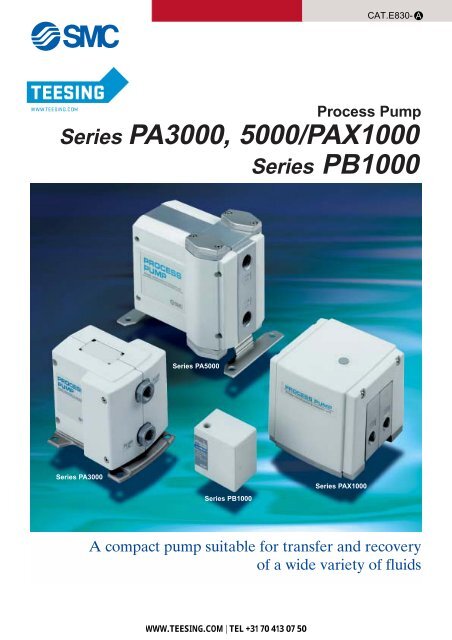
CAT.E830- A<br />
<strong>Process</strong> Pump<br />
<strong>Series</strong> <strong>PA</strong>3000, 5000/<strong>PA</strong>X1000<br />
<strong>Series</strong> <strong>PB</strong>1000<br />
<strong>Series</strong> <strong>PA</strong>5000<br />
<strong>Series</strong> <strong>PA</strong>3000<br />
<strong>Series</strong> <strong>PB</strong>1000<br />
<strong>Series</strong> <strong>PA</strong>X1000<br />
A compact pump suitable for transfer and recovery<br />
of a wide variety of fluids<br />
WWW.TEESING.COM | TEL +31 70 413 07 50
Can be used in almost any field, including machinery, metals, petroleu<br />
Air Pilot Type<br />
<strong>Series</strong> <strong>PA</strong><br />
A compact p<br />
for transfer and recovery<br />
<strong>PA</strong>30 :20l/min<br />
<strong>PA</strong>50 :45l/min<br />
Compact, large capacity diaphragm type pump<br />
Compatible with a wide variety of fluids<br />
<strong>PA</strong>3000:1 to 20l/min, <strong>PA</strong>5000:5 to 45l/min<br />
Long life, 2 to 5 times that of conventional pumps<br />
The diaphragm diameter has been enlarged, the stroke reduced and a new material introduced.<br />
A simple configuration makes maintenance easy too<br />
A new structural design allows the diaphragm and check valve to be replaced individually.<br />
Easy adjustment of discharge pressure and flow rate<br />
Adjustment of discharge pressure and flow rate can be easily performed with adjustment of the pilot air pressure.<br />
Self-priming type makes priming unnecessary<br />
Able to pump up to 1 meter in a dry state (without priming).<br />
(At ordinary temperatures with fresh water) Able to pump up to 6 meters in a wet state (with priming).<br />
High abrasion resistance/low dust generation<br />
Since it is a diaphragm type there are no sliding parts in the liquid contact area.<br />
Features 1<br />
WWW.TEESING.COM | TEL +31 70 413 07 50
ump suitable<br />
of a wide variety of fluids<br />
m, painting, printing, chemistry, foods, semiconductors and electrical.<br />
Built-in pulsation attenuator<br />
<strong>Series</strong> <strong>PA</strong>X<br />
Built-in solenoid valve<br />
<strong>Series</strong> <strong>PB</strong><br />
<strong>PA</strong>X12 1 :10l/min<br />
Built-in pulsation attenuator (standard)<br />
A pulsation attenuating function to suppress<br />
discharge pressure pulsation is a new built-in<br />
feature.<br />
This controls problems such as discharge piping<br />
vibration, scattering of liquid from the discharge<br />
outlet, and foaming in tanks.<br />
In addition, internalization of this feature makes it<br />
unnecessary to provide extra space and separate<br />
piping, etc.<br />
Pump with built-in micro-solenoid valve<br />
A solenoid valve drive type diaphragm pump<br />
that fits in the palm of the hand<br />
• Polypropylene body: 60 x 60 x 41<br />
• Maximum discharge: 2l/min<br />
• Connection port size: Rc(PT)1/8<br />
• Space is saved due to the centralization of<br />
piping and wiring areas on the top and bottom<br />
surfaces.<br />
• Simple adjustment of the discharge flow rate<br />
Adjustment of the discharge flow rate can be<br />
easily performed with the number of ON/OFF<br />
cycles of the internal solenoid valve (VJ300).<br />
Application examples<br />
Transfer of liquid by suction<br />
Atomizing of liquid<br />
Transfer of liquid by pressure<br />
Stirring of liquid<br />
• The suction lift is a maximum of 6m.<br />
(with priming)<br />
• Increases the discharge pressure of the<br />
discharge nozzle.<br />
• Use caution regarding the suction port seal.<br />
• For stirring of liquids that may stick.<br />
WWW.TEESING.COM | TEL +31 70 413 07 50<br />
Features 2
<strong>Process</strong> Pump<br />
Air Pilot Type<br />
<strong>Series</strong> <strong>PA</strong>3000/<strong>PA</strong>5000<br />
How to Order<br />
<strong>PA</strong>3<br />
1 1<br />
0<br />
03<br />
1<br />
2<br />
Body material<br />
ADC12 (aluminium)<br />
SCS14 (stainless steel)<br />
Accessories/Option<br />
AN200-02 Silencer for AIR EXH<br />
1<br />
2<br />
Diaphragm material<br />
1<br />
2<br />
PTFE (fluororesin)<br />
NBR (nitrile rubber)<br />
<strong>PA</strong>5<br />
Body material<br />
ADC12 (aluminium)<br />
SCS14 (stainless steel)<br />
1 1 0 04<br />
Thread type<br />
Nil Rc(PT)<br />
T ∗ NPTF<br />
F ∗ G(PF)<br />
N ∗ NPT<br />
∗ T, F, N are order made specifications.<br />
Accessories/Option<br />
AN200-02 Silencer for AIR EXH<br />
SUP OUT<br />
EXH IN<br />
Automatic operation type<br />
Diaphragm material<br />
1<br />
2<br />
PTFE (fluororesin)<br />
NBR (nitrile rubber)<br />
Connection port size<br />
04<br />
06<br />
1/2 (15A)<br />
3/4 (20A)<br />
SUP<br />
OUT<br />
Specifications<br />
Thread type<br />
Nil Rc(PT)<br />
T* NPTF<br />
F* G(PF)<br />
N* NPT<br />
∗ T, F, N are order made specifications.<br />
EXH<br />
IN<br />
Automatic operation type<br />
Model<br />
<strong>PA</strong>310<br />
<strong>PA</strong>320<br />
Model<br />
<strong>PA</strong>510<br />
<strong>PA</strong>520<br />
Port size<br />
Main fluid suction/<br />
discharge port<br />
Pilot air supply/<br />
exhaust port<br />
Rc(PT) 3/8<br />
Rc(PT) 1/4<br />
Port size<br />
Main fluid suction/<br />
discharge port<br />
Pilot air supply/<br />
exhaust port<br />
Rc(PT) 1/2, 3/4<br />
Rc(PT) 1/4<br />
Material<br />
Suction lifting range<br />
Fluid contact areas<br />
Diaphragm<br />
Check valve<br />
Discharge rate<br />
Average discharge pressure<br />
Pilot air consumption rate<br />
Dry<br />
Wet<br />
ADC12<br />
PTFE, NBR<br />
PTFE, PFA<br />
1 to 20l/min<br />
0 to 0.6MPa (0 to 6.1kgf/cm²)<br />
Maximum 200l/min (ANR)<br />
Up to 1m<br />
(interior of pump dry)<br />
Up to 6m<br />
(liquid inside pump)<br />
SCS14<br />
Material<br />
Suction lifting range<br />
Fluid contact areas<br />
Diaphragm<br />
Check valve<br />
Discharge rate<br />
Average discharge pressure<br />
Pilot air consumption rate<br />
Dry<br />
Wet<br />
ADC12<br />
SCS14<br />
PTFE, NBR<br />
PTFE, PFA<br />
5 to 45l/min<br />
0 to 0.6MPa (0 to 6.1kgf/cm²)<br />
Maximum 300l/min (ANR)<br />
Up to 2m<br />
(interior of pump dry)<br />
Up to 6m<br />
(liquid inside pump)<br />
Fluid temperature<br />
Ambient temperature<br />
Noise value<br />
Pilot air pressure<br />
Withstanding pressure<br />
Mounting orientation<br />
0 to 60°C (without freezing)<br />
0 to 60°C<br />
Max. 92dB (79dB: With silencer AN200)<br />
0.2 to 0.7MPa (2 to 7.1kgf/cm²)<br />
1.05MPa (10.7kgf/cm²)<br />
Horizontal (with mounting foot at bottom)<br />
Weight<br />
1.7kg<br />
2.2kg<br />
∗ Each of the values above indicates use at ordinary temperatures with fresh water.<br />
Fluid temperature<br />
0 to 60°C (without freezing)<br />
Ambient temperature<br />
0 to 60°C<br />
Noise value<br />
Max. 89dB (77dB : With silencer AN200)<br />
Pilot air pressure<br />
0.2 to 0.7MPa (2 to 7.1kgf/cm²)<br />
Withstanding pressure<br />
1.05MPa (10.7kgf/cm²)<br />
Mounting orientation<br />
Horizontal (with mounting foot at bottom)<br />
Weight<br />
3kg<br />
6.5kg<br />
∗ Each of the values above indicates use at ordinary temperatures with fresh water.<br />
1<br />
WWW.TEESING.COM | TEL +31 70 413 07 50
<strong>Process</strong> Pump<br />
Air Pilot Type<br />
<strong>Series</strong> <strong>PA</strong>3000/5000<br />
Fluid Compatibility<br />
Fluid contact materials and models<br />
Liquid contact Body<br />
Models<br />
area<br />
Diaphragm<br />
<strong>Series</strong> <strong>PA</strong>3000<br />
<strong>Series</strong> <strong>PA</strong>5000<br />
Aluminum (ADC12)<br />
Fluororesin<br />
Nitrile rubber<br />
<strong>PA</strong>3110<br />
<strong>PA</strong>3120<br />
<strong>PA</strong>5110<br />
<strong>PA</strong>5120<br />
Stainless steel (SCS14)<br />
Fluororesin<br />
Nitrile rubber<br />
<strong>PA</strong>3210<br />
<strong>PA</strong>3220<br />
<strong>PA</strong>5210<br />
<strong>PA</strong>5220<br />
1. Liquid contact area materials other than the above are: the check valve and O-ring seal which are both fluororesin.<br />
Caution<br />
1. Select models by choosing liquid contact materials suitable for the liquids to be used.<br />
• In liquid contact areas, aluminum is suitable for use with oils, and stainless steel is suitable for solvents and industrial water.<br />
• For the diaphragm material, nitrile rubber is suitable with inert liquids, and fluororesin is suitable with non-permeating liquids.<br />
• Use fluids which will not corrode the liquid contact materials.<br />
2. Transfer examples are shown below. Since the possible applications will change depending on operating conditions, be sure<br />
to confirm by means of experimentation.<br />
3. These products are not suitable for use in medical applications or with food products.<br />
Examples of applicable liquids (reference)<br />
Diaphragm material:<br />
Fluororesin<br />
Diaphragm material:<br />
Nitrile rubber<br />
Body material: aluminium<br />
Ethyl alcohol, Toluene,<br />
Cutting oil, Brake fluid<br />
Turbine oil<br />
Body material: stainless steel<br />
Methyl ethyl ketone, Acetone, Flux,<br />
Isopropyl alcohol, Inert fluorine solvent<br />
Industrial water<br />
Examples of noncompatible liquids (classification)<br />
Body material: aluminium<br />
Diaphragm material:<br />
Fluororesin<br />
Diaphragm material:<br />
Nitrile rubber<br />
Cleaning solvents, Water, Acid-alkali,<br />
High permeation liquids,<br />
High penetration liquids, Corrosive liquids<br />
Cleaning solvents, Water, Solvents,<br />
Acid-alkali, Corrosive liquids<br />
Caution<br />
1. Possible applications will change depending on additive agents. Take note of additives.<br />
2. Possible applications will change depending on impurities. Take note of impurities.<br />
3. Mixing of foreign substances will shorten service life. Operate with foreign substances removed.<br />
4. When transferring liquids subject to coagulation, take measures to prevent coagulation inside the pump.<br />
Body material: stainless steel<br />
Corrosive liquids, Acid-alkali,<br />
High permeation liquids, High penetration liquids<br />
Solvents, Corrosive liquids,<br />
Acid-alkali<br />
WWW.TEESING.COM | TEL +31 70 413 07 50<br />
2
<strong>Series</strong> <strong>PA</strong>3000/5000<br />
Performance Curves<br />
<strong>PA</strong>3000 Flow rate characteristics<br />
<strong>PA</strong>5000 Flow rate characteristics<br />
60<br />
SUP=0.7MPa<br />
60<br />
SUP=0.7MPa<br />
Total lifting range (m)<br />
50<br />
40<br />
30<br />
SUP=0.5MPa<br />
Total lifting range (m)<br />
50<br />
40<br />
30<br />
SUP=0.5MPa<br />
20<br />
10<br />
SUP=0.2MPa<br />
Air consumption 50l/min (ANR)<br />
Air consumption 100l/min (ANR)<br />
Air consumption 100l/min (ANR)<br />
Air consumption 200l/min (ANR)<br />
20<br />
SUP=0.2MPa<br />
10<br />
0<br />
10 20<br />
0<br />
10 20 30 40 50 60<br />
Discharge rate l/min<br />
Discharge rate l/min<br />
Selection from Flow Rate Characteristic Graphs<br />
Required specification example:<br />
Find the pilot air pressure and pilot air consumption rate for a<br />
discharge rate of 6l/min and a total lifting range of 25m. [The<br />
transfer fluid is fresh water (viscosity 1cp, specific gravity 1.0).]<br />
1. First mark the intersection point for a discharge rate of 6l/min<br />
and a lifting range of 25m.<br />
2. Find the pilot air pressure for the marked point. In this case, the<br />
point is between the discharge curves (solid lines) for<br />
SUP=0.2MPa and SUP=0.5MPa, and based on the proportional<br />
relationship to these lines, the pilot air pressure for this point is<br />
approximately 0.38MPa.<br />
3. Next find the air consumption rate. Since the marked point is<br />
below the curve for 50l/min (ANR), the maximum rate will be<br />
about 50l/min (ANR).<br />
Caution<br />
1. These flow rate characteristics are for fresh water (viscosity 1cp,<br />
specific gravity 1.0).<br />
2. The discharge rate differs greatly depending on properties<br />
(viscosity, specific gravity) of the fluid being transferred and<br />
operating conditions (lifting range, transfer distance), etc.<br />
3. Use 0.75kW per 100l/min of air consumption as a guide for the<br />
relationship of the air consumption rate to the compressor.<br />
Selection from Viscosity Characteristic Graph<br />
Required specification example:<br />
Find the pilot air pressure and pilot air consumption rate for a<br />
discharge rate of 2.7l/min, a total lifting range of 25m, and a<br />
viscosity of 100cp.<br />
1. First find the ratio of the discharge rate to fresh water when<br />
viscosity is 100cp from the graph below. It is determined to be<br />
45%.<br />
2. Next, in the required specification example, the viscosity is<br />
100cp and the discharge rate is 2.7l/min. Since this is equivalent<br />
to 45% of the discharge rate for fresh water, 2.7l/min ÷ 0.45 =<br />
6l/min, indicating that a discharge rate of 6l/min is required.<br />
3. Finally, find the pilot air pressure and pilot air consumption rate<br />
based on selections from the flow rate characteristic graphs.<br />
Caution<br />
1. Viscosities up to 1000cp can be used.<br />
Viscosity characteristics (flow rate correction for viscous fluids)<br />
Ratio of discharge rate to fresh water (%)<br />
100<br />
50<br />
0 1 10 100 1000<br />
Viscosity (cp)<br />
3<br />
WWW.TEESING.COM | TEL +31 70 413 07 50
<strong>Process</strong> Pump<br />
Air Pilot Type<br />
<strong>Series</strong> <strong>PA</strong>3000/5000<br />
Operating Principle<br />
Exhaust port<br />
(AIR EXH)<br />
Switching valve<br />
Air supply port<br />
(AIR SUP)<br />
Air switching unit<br />
Pilot<br />
Pilot valve A<br />
Pilot valve B<br />
Discharge port<br />
(FLUID OUT)<br />
Main pump unit<br />
Pump chamber A<br />
Check valve<br />
Shaft<br />
Pump chamber B<br />
Diaphragm A<br />
Drive chamber A<br />
Drive chamber B<br />
Diaphragm B<br />
Suction port<br />
(FLUID IN)<br />
Pilot air switching unit<br />
When air is supplied, it passes through the switching valve and<br />
enters drive chamber A. When air enters drive chamber A,<br />
diaphragm A moves to the left, and at the same time diaphragm B<br />
also moves to the left pushing pilot valve B. When pilot valve B is<br />
pressed, air acts upon the switching valve and this time drive<br />
chamber B is switched to a supply state. At this time, the air which<br />
was in drive chamber A goes through the exhaust passage and is<br />
exhausted to the outside. When air enters drive chamber B,<br />
diaphragm A moves to the right pressing pilot valve A. When pilot<br />
valve A is pressed, the air which was acting upon the switching<br />
valve is exhausted, and drive chamber A once again switches to a<br />
supply state. A contiuous reciprocal motion is generated by this<br />
repetition.<br />
Main pump unit<br />
When air enters drive chamber A, the fluid in pump chamber A is<br />
pushed out. At the same time, fluid is sucked into pump chamber B.<br />
When the diaphragm moves in the opposite direction, the fluid in<br />
pump chamber B is pushed out, and fluid is sucked into pump<br />
chamber A. Continuous suction/discharge is performed by the<br />
reciprocal motion of the diaphragm.<br />
WWW.TEESING.COM | TEL +31 70 413 07 50<br />
4
<strong>Series</strong> <strong>PA</strong>3000/5000<br />
Piping and Operation<br />
Piping diagram<br />
Discharge port<br />
FLUID OUT<br />
Suction port<br />
FLUID IN<br />
∗ Maintain the proper tightening torque for fittings and mounting bolts, etc. Looseness can cause problems such as fluid and air leaks,<br />
while over tightening can cause damage to threads and parts, etc.<br />
Operation<br />
Refer to circuit example (1)<br />
1. Connect air piping to the air supply port and connect<br />
piping for the fluid to be transferred to the suction port and the discharge port .<br />
2. Using a regulator, set the pilot pressure within the range of 0.2 to<br />
0.7MPa (2 to 7.1kgf/cm²). Then, the pump operates when power<br />
is applied to the 3 port solenoid valve of the air supply port , the sound of exhaust begins from the air exhaust port<br />
and fluid flows from the suction port to<br />
the discharge port . At this time, the ball valve on<br />
the discharge side is in an open state. The pump performs<br />
suction with its own power even without priming. (Dry state<br />
suction lifting range: max. 2m) To restrict exhaust noise, attach a<br />
silencer (AN200-02: option) to the air exhaust port .<br />
3. To stop the pump, exhaust the air pressure being supplied to the<br />
pump with the 3 port solenoid valve of the air supply port . The pump will also stop if the ball valve on the discharge<br />
side is closed.<br />
<br />
1. Adjustment of the flow rate from the discharge port is performed with the ball valve connected on the<br />
discharge side or the throttle connected on the air exhaust side.<br />
For adjustment from the air side, use of the silencer with throttle<br />
ASN2 (port size 1/4) connected to the air exhaust port is effective. Refer to circuit example (1).<br />
2. When operating with a discharge flow rate below the<br />
specification range, provide a by-pass circuit from the discharge<br />
side to the suction side to ensure the minimum flow rate inside<br />
the process pump. With a discharge flow rate below the<br />
minimum flow rate, the process pump may stop due to unstable<br />
operation. Refer to circuit example (2). (Minimum flow rates:<br />
<strong>PA</strong>3000 1l/min, <strong>PA</strong>5000 5l/min)<br />
<br />
1. When the pump stops during operation, press the reset button.<br />
This makes it possible to restore operation in case the switching<br />
valve becomes clogged due to foreign substances in the supply<br />
air.<br />
Circuit example (1)<br />
Circuit example (2)<br />
Air filter<br />
Regulator<br />
3 port<br />
solenoid valve<br />
AIR<br />
SUP<br />
<strong>Process</strong> pump<br />
FLUID<br />
OUT<br />
Ball valve<br />
<strong>Process</strong> pump<br />
Air supply<br />
AIR<br />
EXH<br />
FLUID<br />
IN<br />
Strainer<br />
By-pass<br />
Silencer<br />
Throttle<br />
Transfer fluid<br />
5<br />
WWW.TEESING.COM | TEL +31 70 413 07 50
<strong>Process</strong> Pump<br />
Air Pilot Type<br />
<strong>Series</strong> <strong>PA</strong>3000/5000<br />
Dimensions<br />
<strong>PA</strong>3000<br />
FLUID OUT<br />
Rc(PT) 3/8<br />
FLUID<br />
OUT<br />
Reset button<br />
AIR SUP<br />
(pilot air supply port)<br />
Rc(PT) 1/4<br />
5.5<br />
90<br />
PROCESS<br />
PUMP<br />
AIR<br />
SUP<br />
2<br />
115<br />
32<br />
FLUID<br />
I N<br />
3<br />
AIR EXH<br />
(pilot air exhaust port)<br />
Rc(PT) 1/4<br />
AIR<br />
EXH<br />
44.5<br />
FLUID IN<br />
Rc(PT) 3/8<br />
130<br />
100<br />
<strong>PA</strong>5000<br />
56<br />
112<br />
165<br />
56<br />
RESET<br />
FLUID<br />
OUT<br />
PROCESS<br />
PUMP<br />
AIR<br />
SUP<br />
FLUID<br />
I N<br />
AIR<br />
EXH<br />
48.5<br />
58.5<br />
68<br />
85<br />
74.5<br />
4-ø7 105<br />
7.5<br />
(185)<br />
FLUID OUT<br />
Rc(PT) 1/2, 3/4<br />
AIR SUP<br />
(pilot air supply port)<br />
Rc(PT) 1/4<br />
Reset button<br />
167<br />
132.5<br />
103.5<br />
125.5<br />
114 202<br />
3 3.5<br />
FLUID IN<br />
Rc(PT) 1/2, 3/4<br />
179 4-ø9<br />
AIR EXH<br />
(pilot air exhaust port)<br />
Rc(PT) 1/4<br />
90<br />
90<br />
(257)<br />
WWW.TEESING.COM | TEL +31 70 413 07 50<br />
6
<strong>Process</strong> Pump<br />
Built-in Pulsation Attenuator Type<br />
<strong>Series</strong> <strong>PA</strong>X1000<br />
How to Order<br />
<strong>PA</strong>X1<br />
1 1 2 02<br />
1<br />
2<br />
Body material<br />
ADC12 (aluminium)<br />
SCS14 (stainless steel)<br />
Diaphragm material<br />
1 PTFE (fluororesin)<br />
2<br />
Type of operation<br />
Automatic operation type with<br />
built-in pulsation attenuator<br />
Accessories/Option<br />
AN200-02 Silencer for AIR EXH<br />
Connection port size<br />
02<br />
03<br />
Thread type<br />
Nil Rc(PT)<br />
T ∗ NPTF<br />
F ∗ G(PF)<br />
N ∗ NPT<br />
1/4 (8A)<br />
3/8 (10A)<br />
∗ T, F, N are order made specifications.<br />
SUP<br />
EXH<br />
JIS symbol<br />
OUT<br />
IN<br />
Built-in Pulsation Attenuator<br />
Automatic operation type<br />
Performance Curves<br />
Specifications<br />
70<br />
Model<br />
<strong>PA</strong>X1112<br />
<strong>PA</strong>X1212<br />
Total lifting range (m)<br />
60<br />
50<br />
40<br />
30<br />
20<br />
10<br />
SUP=0.7MPa<br />
SUP=0.5MPa<br />
SUP=0.2MPa<br />
Air consumption 50l/min(ANR)<br />
Air consumption 30l/min(ANR)<br />
Port size<br />
Material<br />
Suction lifting range<br />
Main fluid suction/<br />
discharge port<br />
Pilot air supply/<br />
exhaust port<br />
Fluid contact areas<br />
Diaphragm<br />
Check valve<br />
Discharge rate<br />
Average discharge pressure<br />
Pilot air consumption rate<br />
Dry<br />
Wet<br />
Rc(PT) 1/4, 3/8<br />
Rc(PT) 1/4<br />
ADC12<br />
SCS14<br />
PTFE<br />
PTFE, SCS14<br />
0.5 to 10l/min<br />
0 to 0.6MPa (0 to 6.1kgf/cm²)<br />
Maximum 150l/min (ANR)<br />
Up to 2m<br />
(interior of pump dry)<br />
Up to 6m<br />
(liquid inside pump)<br />
0 5<br />
Discharge rate l/min<br />
10<br />
Discharge pulsation attenuating capacity<br />
Fluid temperature<br />
Ambient temperature<br />
Noise value<br />
Pilot air pressure<br />
Withstanding pressure<br />
Mounting orientation<br />
30% or less of maximum discharge pressure<br />
0 to 60°C (without freezing)<br />
0 to 60°C<br />
Max. 93dB (84dB : With silencer AN200)<br />
0.2 to 0.7MPa (2 to 7.1kgf/cm²)<br />
1.05MPa (10.7kgf/cm²)<br />
Horizontal (bottom facing down)<br />
Weight<br />
2.0kg<br />
3.5kg<br />
∗ Each of the values above indicates use at ordinary temperatures with fresh water.<br />
7<br />
WWW.TEESING.COM | TEL +31 70 413 07 50
<strong>Process</strong> Pump<br />
Built-in Pulsation Attenuator Type <strong>Series</strong> <strong>PA</strong>X1000<br />
Fluid Compatibility<br />
Fluid contact materials and models<br />
Models<br />
Liquid contact<br />
area<br />
<strong>Series</strong> <strong>PA</strong>X1000<br />
Body<br />
Diaphragm<br />
Aluminium (ADC12)<br />
Fluororesin<br />
<strong>PA</strong>X1112<br />
Stainless steel (SCS14)<br />
Fluororesin<br />
<strong>PA</strong>X1212<br />
1. Liquid contact area materials other than the above are: check valve/stainless steel (SCS14), and O-ring seal/fluororesin (PTFE).<br />
Caution<br />
1. Select models by choosing liquid contact materials suitable for the liquids to be used.<br />
• In liquid contact areas, aluminum is suitable for use with oils, and stainless steel is suitable for solvents and industrial water.<br />
• Since fluororesins is used for the diaphragm, non-permeating liquids should be used.<br />
• Use fluids which will not corrode the liquid contact materials.<br />
2. Transfer examples are shown below. Since the possible applications will change depending on operating conditions, be sure to<br />
confirm by means of experimentation.<br />
3. These products are not suitable for use in medical applications or with food products.<br />
Examples of applicable liquids (reference)<br />
Diaphragm material:<br />
Fluororesin<br />
Body material: aluminium<br />
Ethyl alcohol, Toluene,<br />
Cutting oil, Brake fluid<br />
Body material: stainless steel<br />
Methyl ethyl ketone, Acetone, Flux,<br />
Isopropyl alcohol, Inert fluorine solvent<br />
Examples of noncompatible liquids (classification)<br />
Body material: aluminum<br />
Diaphragm material:<br />
Fluororesin<br />
Cleaning solvents, Water, Acid-alkali,<br />
High permeation liquids,<br />
High penetration liquids, Corrosive liquids<br />
Caution<br />
1. Possible applications will change depending on additive agents. Take note of additives.<br />
2. Possible applications will change depending on impurities. Take note of impurities.<br />
3. Mixing of foreign substances will shorten service life. Operate with foreign substances removed.<br />
4. When transferring liquids subject to coagulation, take measures to prevent coagulation inside the pump.<br />
Body material: stainless steel<br />
Corrosive liquids, Acid-alkali,<br />
High permeation liquids, High penetration liquids<br />
WWW.TEESING.COM | TEL +31 70 413 07 50<br />
8
<strong>Series</strong> <strong>PA</strong>X1000<br />
Piping<br />
Piping diagram<br />
Reset button<br />
Reset button<br />
Pilot air supply port<br />
AIR SUP<br />
PROCESS PUMP<br />
Discharge port<br />
FLUID OUT<br />
Silencer<br />
Pilot air exhaust port<br />
AIR EXH<br />
Suction port<br />
FLUID IN<br />
• Piping is connected to each of 4 ports as shown<br />
in the drawing above.<br />
Caution<br />
Maintain the proper tightening torque for<br />
fittings and mounting bolts, etc. Looseness<br />
can cause problems such as fluid leakage,<br />
while over tightening can cause damage to<br />
threads and parts, etc.<br />
Circuit example (1)<br />
Air filter<br />
Air supply<br />
Regulator<br />
3 port<br />
solenoid valve<br />
AIR<br />
SUP<br />
<strong>Process</strong> pump<br />
<strong>PA</strong>X112<br />
AIR<br />
EXH<br />
FLUID<br />
OUT<br />
FLUID<br />
IN<br />
Strainer<br />
Ball valve<br />
Construction and Principles<br />
Silencer<br />
Throttle<br />
Transfer fluid<br />
Switching valve<br />
Air exhaust port<br />
(AIR EXH)<br />
Air supply port<br />
(AIR SUP)<br />
Pulsation attenuator<br />
exhaust valve<br />
Change lever<br />
Pulsation attenuator<br />
intake valve<br />
Pilot valve A<br />
Pilot valve B<br />
Control unit<br />
Pump chamber A<br />
Drive unit<br />
Check valve<br />
Shaft<br />
Diaphragm A<br />
Drive chamber A<br />
Pump chamber B<br />
Drive chamber B<br />
Suction port Discharge port<br />
(FLUID IN) (FLUID OUT)<br />
Pulsation<br />
attenuator air chamber<br />
Pulsation<br />
attenuation chamber<br />
9<br />
WWW.TEESING.COM | TEL +31 70 413 07 50
Pulsation Attenuating Capacity<br />
<strong>Process</strong> Pump<br />
Built-in Pulsation Attenuator Type <strong>Series</strong> <strong>PA</strong>X1000<br />
MPa<br />
0.7<br />
0.5<br />
The process pump generates pulsation because it discharges a<br />
liquid using two diaphragms. The pulsation attenuator absorbs<br />
pressure when discharge pressure increases, and compensates<br />
the pressure when discharge pressure decreases. By this means<br />
pulsation is controlled.<br />
0<br />
0<br />
Without pulsation attenuator<br />
MPa<br />
0.7<br />
0.5<br />
With built-in pulsation attenuator<br />
Dimensions<br />
AIR SUP<br />
(pilot air supply port)<br />
Rc(PT) 1/4<br />
FLUID<br />
IN<br />
FLUID<br />
OUT<br />
FLUID IN<br />
Rc(PT) 1/4, 3/8<br />
FLUID OUT<br />
Rc(PT) 1/4, 3/8<br />
33<br />
PROCESS PUMP<br />
110<br />
AIR<br />
SUP<br />
AIR<br />
EXH<br />
45 29<br />
32.5 45.5<br />
120<br />
Bottom<br />
75 5<br />
AIR EXH<br />
(pilot air exhaust port)<br />
Rc(PT) 1/4<br />
4-M8<br />
(M6 hexagon socket head screw<br />
can be inserted)<br />
10.5<br />
7.5<br />
105<br />
Mounting hole detail<br />
SUP<br />
OUT<br />
125<br />
100<br />
Reset button<br />
69<br />
23<br />
EXH<br />
IN<br />
RESET<br />
Automatic operation type<br />
with built-in pulsation attenuator<br />
(175)<br />
WWW.TEESING.COM | TEL +31 70 413 07 50<br />
10
<strong>Process</strong> Pump<br />
Built-in Solenoid Valve Type<br />
<strong>Series</strong> <strong>PB</strong>1000<br />
How to Order<br />
<strong>PB</strong>1 0 1 1 01<br />
1<br />
Body size<br />
1/8 standard<br />
Accessories/Option<br />
AN120-M5 Silencer for AIR EXH ∗<br />
KT-<strong>PB</strong>1-3 Foot (bolts included)<br />
∗ External air operated type is not available with silencer.<br />
Body material Diaphragm material<br />
0 Polypropylene 1 PTFE (fluororesin)<br />
1<br />
3<br />
Type of operation<br />
Built-in solenoid valve<br />
External air operated<br />
Nil<br />
T ∗<br />
F ∗<br />
N ∗<br />
Connection port size<br />
01<br />
Thread type<br />
Rc(PT)<br />
NPTF<br />
G(PF)<br />
NPT<br />
1/8 (6A)<br />
∗ T, F, N are order made specifications.<br />
Specifications<br />
EXH<br />
SUP<br />
Symbol<br />
IN<br />
OUT<br />
Main fluid suction/discharge port<br />
Port size<br />
Pilot air<br />
Supply port<br />
Exhaust port<br />
Material<br />
Fluid contact areas<br />
Diaphragm<br />
Check valve<br />
Liquid contact seals<br />
<strong>PB</strong>1011<br />
Discharge rate<br />
<strong>PB</strong>1013<br />
Average discharge pressure<br />
Suction lifting range (Dry: interior of the pump is dry)<br />
Fluid temperature<br />
Ambient temperature<br />
Pilot air pressure<br />
Withstanding pressure<br />
Maximum operating frequency<br />
Lubrication<br />
Voltage (<strong>PB</strong>1011)<br />
Weight<br />
Mounting orientation<br />
Rc(PT) 1/8<br />
Rc(PT) 1/8<br />
M5 x 0.8<br />
Polypropylene PP, Stainless steel (SUS316)<br />
PTFE<br />
PTFE<br />
FKM<br />
8 to 2000ml/min<br />
8 to 500ml/min<br />
0 to 0.6MPa {0 to 6.1kgf/cm²}<br />
Up to 2.5m<br />
0 to 50°C (without freezing)<br />
0 to 50°C<br />
0.2 to 0.7MPa {2 to 7.1kgf/cm²}<br />
1.05MPa (10.7kgf/cm²)<br />
10c/s<br />
Not required<br />
24VDC<br />
0.17kg<br />
OUT port at top (indication on name plate)<br />
∗ Each of the values above indicates use at ordinary temperatures with fresh water.<br />
Note on the transfer of slurry:<br />
Slurry transfer is not possible with <strong>Series</strong> <strong>PB</strong>1000 because of deterioration and wear of the check valve<br />
seat and the accumulation of particles, which will render the pump inoperable.<br />
11<br />
WWW.TEESING.COM | TEL +31 70 413 07 50
<strong>Process</strong> Pump<br />
Built-in Solenoid Valve Type <strong>Series</strong> <strong>PB</strong>1000<br />
Fluid Compatibility<br />
Liquid contact parts table<br />
Liquid contact part description Liquid contact part material<br />
Diaphragm<br />
Fluororesin<br />
Body<br />
Polypropylene, SUS316<br />
Seals<br />
Fluororubber<br />
Note ) Liquid contact area material other than the above is: check<br />
valve/fluororesin.<br />
Flow rate characteristics<br />
Caution<br />
1. Give careful consideration to the transfer fluid to be used and the<br />
fluid contact materials.<br />
• Since fluororesin is used for the diaphragm material, use liquids<br />
which will not permeate or penetrate it.<br />
• Since there is a built-in solenoid valve, this product cannot be<br />
used for the transfer of flammable fluids. (<strong>PB</strong>1011)<br />
• Use fluids which will not corrode the liquid contact materials.<br />
2. These products are not suitable for use in medical applications or<br />
with food products.<br />
70<br />
70<br />
Total lifting range (m)<br />
60<br />
50<br />
40<br />
3<br />
30<br />
1<br />
20<br />
5Nl/min<br />
0.7MPa<br />
0.5<br />
0.35<br />
0.2<br />
Solenoid valve ON/OFF = 0.5s/0.5s<br />
Discharge lifting range for each pilot air pressure<br />
Pilot air consumption rate<br />
Total lifting range (m)<br />
60<br />
50<br />
40<br />
30<br />
20<br />
12 Nl/min<br />
8<br />
5<br />
Solenoid valve ON/OFF = 0.1s/0.1s<br />
0.7MPa<br />
0.5<br />
0.35<br />
0.2<br />
Discharge lifting range for each pilot air pressure<br />
Pilot air consumption rate<br />
10<br />
10<br />
0<br />
0 500<br />
(8.3)<br />
1000<br />
Discharge rate l/min<br />
(ml/1shot)<br />
1500 2000<br />
0<br />
0 500<br />
(1.7)<br />
1000<br />
(3.3)<br />
Discharge rate l/min<br />
(ml/1 shot)<br />
1500<br />
(5)<br />
2000<br />
Required specification example:<br />
Find the pilot air pressure and pilot air consumption rate for a<br />
discharge rate of 600ml/min and a total lifting range of 15m.<br />
[The transfer fluid is fresh water (viscosity 1cp, specific gravity 1.0),<br />
and the solenoid valve ON/OFF= 0.1s/0.1s]<br />
1. First mark the intersection point for a discharge rate of 600ml/min<br />
and a lifting range of 15m.<br />
2. Find the pilot air pressure for the marked point. In this case, the<br />
point is between the discharge curves (solid lines) for<br />
SUP=0.35MPa and SUP=0.5MPa, and based on the proportional<br />
relationship to these lines, the pilot air pressure for this point is<br />
approximately 0.4MPa.<br />
3. Next find the air consumption rate. The marked point is between the<br />
curves for 8Nl/min and 12Nl/min, and based on the proportional<br />
relationship to these lines, it is determined that the pilot air<br />
consumption rate for this point is 9Nl/min.<br />
Solenoid valve ON/OFF time<br />
The discharge rate also depends on the ON/OFF time of the solenoid<br />
valve. Set an appropriate time using the flow rate characteristics as<br />
criteria. Furthermore, set the ON/OFF time to no less than 0.02s/0.06s<br />
for the maximum discharge rate of 2000ml/min.<br />
Caution<br />
1. These flow rate characteristics are for fresh water (viscosity 1cp,<br />
specific gravity 1.0).<br />
2. The discharge rate differs greatly depending on properties (viscosity,<br />
specific gravity) of the fluid being transferred and operating<br />
conditions (lifting range, transfer distance), etc.<br />
3. When compressor output is selected based on the air consumption<br />
rate, use 0.75kW for 100l/min of air consumption as a criteria.<br />
Viscosity characteristics (flow rate correction for viscous fluids)<br />
Ratio of discharge rate to fresh water (%)<br />
100<br />
50<br />
0<br />
1 10 100<br />
Viscosity [cp]<br />
Required specification example:<br />
Find the pilot air pressure and pilot air consumption rate for a discharge<br />
rate of 200ml/min, a total lifting range of 10m, and a viscosity of 15cp.<br />
1. First find the ratio of the discharge rate to fresh water when viscosity<br />
is 15cp from the graph to the left. It is determined to be 48%.<br />
2. Next, the viscosity of 15cp and the discharge rate of 200l/min in the<br />
required specification example, are converted to the discharge rate<br />
for fresh water. Since 48% of the fresh water discharge rate is<br />
equivalent to 200ml/min in the required specifications, 200ml/min ÷<br />
0.48 = approximately 420ml/min, indicating that a discharge rate of<br />
420ml/min is required for fresh water.<br />
3. Finally, find the pilot air pressure and pilot air consumption rate<br />
based on viewing of the flow rate characteristics.<br />
Viscosity: Transfer is possible up to about 100cp.<br />
WWW.TEESING.COM | TEL +31 70 413 07 50<br />
12
<strong>Series</strong> <strong>PB</strong>1000<br />
Piping and Operation<br />
Discharge port OUT<br />
Piping is connected to each of 4 ports as shown in the drawing to the left.<br />
The solenoid valve lead wires are connected to a 24VDC power supply.<br />
Circuit example<br />
Piping<br />
(V)<br />
24<br />
0<br />
ON/OFF signal<br />
Suction port IN<br />
Foot<br />
(optional)<br />
Air supply port SUS<br />
Air exhaust port EXH<br />
Solenoid valve lead wires<br />
Filter<br />
Air supply<br />
Regulator<br />
EXH<br />
SUP<br />
<strong>Process</strong> pump<br />
<strong>PB</strong>1011<br />
OUT<br />
IN<br />
Top view<br />
Manual override pin<br />
Transfer fluid<br />
Names and Functions of Ports<br />
IN Suction Port<br />
Connects to piping for the<br />
transfer fluid.<br />
OUT Discharge Port<br />
SUP<br />
EXH<br />
Discharges the fluid which has<br />
been sucked into the pump.<br />
Pilot Air Supply Port<br />
Supplies the pressure which is<br />
set by a regulator, etc. Use clean<br />
air.<br />
Pilot Air Exhaust Port<br />
Discharges the pilot air.<br />
1<br />
2<br />
3<br />
4<br />
Operation<br />
Connect air piping to the air supply port SUP, and connect piping for<br />
the transfer fluid to the suction port IN and the discharge port OUT.<br />
Connect the solenoid valve lead wires to a 24VDC power supply.<br />
Red is (+) and Black is (–).<br />
Using a regulator, set the pilot air pressure within the range of<br />
0.2 to 0.7MPa (2 to 7kgf/cm²). By continuously turning the 24VDC<br />
power ON/OFF the fluid flows from the suction port IN to the<br />
discharge port OUT. The pump performs suction with its own power<br />
even without priming.<br />
To stop the pump turn OFF the 24VDC power. Also be sure to turn<br />
OFF the power when the discharge side is closed.<br />
Solenoid Valve Lead Wires<br />
Connect to 24VDC power supply.<br />
Red (+), Black (–)<br />
Caution<br />
Be sure that the discharge side OUT is on top when the pump is mounted.<br />
Supply clean air that has passed through an AF filter, etc. to the air supply port<br />
SUP.<br />
Air that contains debris or drainage, etc. will have an adverse effect on the built-in<br />
solenoid valve, and will cause malfunction of the pump. In cases that particularly<br />
require air cleaning, use a filter (<strong>Series</strong> AF) together with a mist separator (<strong>Series</strong><br />
AM).<br />
Manual Override Pin<br />
Presses the manual override button for<br />
the solenoid valve. Pushing once<br />
operates the valve one time without<br />
turning on the power.<br />
13<br />
WWW.TEESING.COM | TEL +31 70 413 07 50
<strong>Process</strong> Pump<br />
Built-in Solenoid Valve Type <strong>Series</strong> <strong>PB</strong>1000<br />
Construction and Operation<br />
Discharge port OUT<br />
Pump<br />
chamber<br />
Diaphragm<br />
Drive chamber<br />
Return spring<br />
Built-in solenoid valve<br />
Operating Principle<br />
When air is supplied and the built-in solenoid valve is turned ON, air<br />
enters the drive chamber and the diaphragm moves to the left. Due to<br />
this movement, the fluid in the pump chamber passes through the<br />
upper check valve and is discharged to the OUT side.<br />
When the solenoid valve is turned OFF, the air inside the drive<br />
chamber is evacuated to EXH, and the diaphragm is moved to the<br />
right by the return force of the return spring. Due to this movement,<br />
the fluid on the IN side passes through the lower check valve and is<br />
sucked into the pump chamber.<br />
The pump repeats this suction and discharge with the repetition of the<br />
solenoid valve's ON/OFF operation.<br />
Dimensions<br />
Suction port IN<br />
SUP<br />
Pilot air supply port<br />
EXH<br />
Pilot air exhaust port<br />
<strong>PB</strong>1000<br />
SUP (Pilot air supply) port<br />
Rc(PT) 1/8<br />
IN port<br />
Suction port Rc(PT) 1/8 11 22<br />
13<br />
9<br />
32<br />
11<br />
18.5<br />
EXH<br />
SUP IN<br />
2-M4 x 0.7<br />
Female threads for mounting<br />
Thread depth 6<br />
45<br />
EXH (pilot air exhaust) port<br />
M5 x 0.8<br />
Thread depth 10<br />
84<br />
72<br />
45<br />
41<br />
7.5<br />
60<br />
Mount with this surface<br />
(OUT port side) on top<br />
2-ø4.5<br />
Mounting hole<br />
57<br />
16<br />
PROCESS<br />
PUMP<br />
MODEL <strong>PB</strong>1011<br />
SUPPLY PRESS<br />
AIR 0.2 to 0.7MPa<br />
VOLTAGE<br />
DC ON<br />
OFF<br />
(78.1)<br />
UP SIDE<br />
Mounting<br />
position<br />
MADE IN<br />
JA<strong>PA</strong>N<br />
2-M4 x 0.7<br />
Female threads for mounting<br />
Thread depth 6<br />
16<br />
17.5<br />
OUT port Rc(PT) 1/8<br />
Discharge port<br />
11<br />
OUT<br />
WWW.TEESING.COM | TEL +31 70 413 07 50<br />
11<br />
14
Related Products<br />
Related Products (Refer to the individual product catalogs for further details.)<br />
(BC Sintered Body)<br />
<strong>Series</strong> AN120<br />
Ideal for compact valves and<br />
pilot air exhaust, etc.<br />
JIS symbol<br />
<strong>Series</strong> AN200<br />
Noise reduction of 30dB (A) or more<br />
Low air flow resistance<br />
Compact and easy to mount<br />
JIS symbol<br />
Mist Separator<br />
<strong>Series</strong> AM<br />
<strong>Series</strong> AM separates and removes<br />
the oil mist in compressed air which<br />
is troublesome for ordinary filters,<br />
and removes fine particles of rust<br />
and carbon, etc. of 0.3µm or larger.<br />
Should be used with an air supply<br />
for driving pilot type and metal type<br />
solenoid valves.<br />
Specifications<br />
Fluid<br />
Maximum operating pressure<br />
Noise reduction<br />
Ambient and fluid temperature<br />
Models<br />
Model<br />
AN120-M5<br />
Specifications<br />
Fluid<br />
Maximum operating pressure<br />
Noise reduction<br />
Ambient and fluid temperature<br />
Models<br />
Model<br />
AN200-02<br />
Port size<br />
R(PT)<br />
M5<br />
Port size<br />
R(PT)<br />
1/4<br />
Specifications<br />
Fluid<br />
Maximum operating pressure<br />
Min. operating pressure*<br />
Proof pressure<br />
Ambient and fluid<br />
temperature<br />
Filtration degree<br />
Downstream oil<br />
mist concentration<br />
Element life<br />
Compressed air<br />
1.0MPa {10.2kgf/cm²}<br />
18dB (A)<br />
5 to 150°C ∗<br />
∗ Can be used at -10 to 150°C when there is no danger of water<br />
droplets being generated from the fluid.<br />
Effective sectional<br />
area mm²<br />
Compressed air<br />
1.0MPa {10.2kgf/cm²}<br />
30dB (A) or more<br />
5 to 60°C ∗<br />
Effective sectional<br />
area mm²<br />
35<br />
Weight<br />
g<br />
3.3<br />
∗ Can be used at -10 to 60°C when there is no danger of water droplets<br />
being generated from the fluid and freezing.<br />
Weight<br />
g<br />
17<br />
Compressed air<br />
1.0MPa {10.2kgf/cm²}<br />
0.05MPa {0.51kgf/cm²}<br />
1.5MPa {15.3kgf/cm²}<br />
5 to 60°C<br />
0.3µm (95% filtered particle diameter)<br />
Max.1.0mg/m³ (ANR) ∗<br />
(Approx. 0.8ppm)<br />
2 years, or when pressure drop<br />
reaches 0.1MPa {1.0kgf/cm²}<br />
∗ N.O. with auto drain is 0.15MPa (1.5kgf/cm²)<br />
∗ When compressor discharge oil mist concentration is 30mg/m³ (ANR)<br />
Models<br />
Model<br />
Rated flow rate<br />
l/min (ANR)<br />
Port size<br />
(nominal size B)<br />
Weight (kg)<br />
AM150<br />
5<br />
AM250<br />
300 750<br />
1/8, 1/4, 3/8 1/4, 3/8, 1/2<br />
0.38 0.55<br />
Construction/Parts, Dimensions<br />
AN120<br />
ø8<br />
17<br />
Construction/Parts, Dimensions<br />
AN200 ø22<br />
End plate<br />
(polyacetal)<br />
Sound absorbing material<br />
(PE sintered body)<br />
63<br />
How to Order<br />
AM 250 03 B J<br />
Body size<br />
150 – 1/8 standard<br />
250 – 1/4 standard<br />
350 – 3/8 standard<br />
450 – 1/2 standard<br />
550 – 3/4 standard<br />
650 – 1 standard<br />
850 – 1 1/2 standard<br />
Thread type<br />
Nil ––––– Rc(PT)<br />
F ––––––– G(PF)<br />
N ––––––– NPT<br />
Port size<br />
01 – 1/8 B 06 – 3/4 B<br />
02 – 1/4 B 10 – 1<br />
03 – 3/8 B 14 – 1 1/2 B<br />
04 – 1/2 B 20 – 2 B<br />
BC sintered body<br />
Phosphor bronze<br />
Port size<br />
Case<br />
(polyacetal)<br />
Hexagon section<br />
width across flats<br />
19<br />
Port size<br />
Order made specification ∗<br />
J – Drain guide 1/4 B female threads<br />
R – IN, OUT in opposite directions<br />
T – Clogging checker<br />
Accessories (optional) ∗<br />
Symbol Description<br />
Nil<br />
–<br />
B<br />
Bracket<br />
C N.C. auto drain<br />
D N.O. auto drain<br />
∗ Refer to the table below regarding<br />
the combination of accessories<br />
with order made specifications.<br />
Filter Regulator + Mist Separator<br />
Air Combination<br />
<strong>Series</strong> AC2040, 3040<br />
Maintenance Parts Lists<br />
Standard specifications<br />
Model<br />
Component<br />
devices<br />
Port size Rc(PT)<br />
Filter regulator<br />
Mist separator<br />
Pressure gauge port size Rc(PT)<br />
AC2040<br />
AW2000<br />
AFM2000<br />
1/8<br />
1/4<br />
AC3040<br />
AW3000<br />
AFM3000<br />
1/4<br />
3/8<br />
1/8 1/8<br />
<strong>PA</strong>X1000<br />
Diaphragm kit (PTFE)<br />
Check valve kit<br />
Switching valve parts kit<br />
Pilot valve kit<br />
Pulsation attenuator control valve kit<br />
KT-<strong>PA</strong>X1-31<br />
KT-<strong>PA</strong>X1-36<br />
KT-<strong>PA</strong>X1-37<br />
KT-<strong>PA</strong>5-38<br />
KT-<strong>PA</strong>X1-39<br />
<strong>PA</strong>3000<br />
Diaphragm kit (PTFE)<br />
Diaphragm kit (NBR)<br />
Check valve kit<br />
Switching valve assembly kit<br />
Pilot valve kit<br />
KT-<strong>PA</strong>3-31<br />
KT-<strong>PA</strong>3-32<br />
KT-<strong>PA</strong>3-36<br />
KT-<strong>PA</strong>3-37<br />
KT-<strong>PA</strong>5-38<br />
<strong>PA</strong>5000<br />
Diaphragm kit (PTFE)<br />
Diaphragm kit (NBR)<br />
Check valve kit<br />
Switching valve parts kit<br />
Pilot valve kit<br />
KT-<strong>PA</strong>5-31<br />
KT-<strong>PA</strong>5-32<br />
KT-<strong>PA</strong>5-36<br />
KT-<strong>PA</strong>5-37<br />
KT-<strong>PA</strong>5-38<br />
<strong>PB</strong>1000<br />
Diaphragm kit<br />
Check valve kit<br />
Built-in solenoid valve kit<br />
KT-<strong>PB</strong>1-2<br />
KT-<strong>PB</strong>1-1<br />
VJ314MY-5H<br />
15<br />
WWW.TEESING.COM | TEL +31 70 413 07 50
<strong>Process</strong> Pump<br />
Safety Instructions<br />
These safety instructions are intended to prevent a hazardous situation and/or<br />
equipment damage. These instructions indicate the level of potential hazard by a<br />
label of "Caution", "Warning" or "Danger". To ensure safety, be sure to observe<br />
ISO4413 Note 1) , ISO4414 Note 2) , JISB8361 Note 3) , JISB8370 Note 4) , JISZ9102 Note 5)<br />
and other safety practices.<br />
Caution : Operator error could result in injury or equipment damage.<br />
Warning : Operator error could result in serious injury or loss of life.<br />
Danger : In extreme conditions, there is a possible result of serious injury or loss of life.<br />
Note 1) ISO4413: Hydraulic fluid power-General rules for the application of equipment to transmission and control systems.<br />
Note 2) ISO4414: Pneumatic fluid power -- Recommendations for the application of equipment to transmission and control<br />
systems.<br />
Note 3) JISB8361: Hydraulic system axiom<br />
Note 4) JISB8370: Pneumatic system axiom.<br />
Note 5) JISZ9102: Piping identification marking<br />
Warning<br />
1. The compatibility of pneumatic equipment is the responsibility of the person<br />
who designs the pneumatic system or decides its specifications.<br />
Since the products specified here are used in various operating conditions, their compatibility for the<br />
specific pneumatic system must be based on specifications or after analysis and/or tests to meet your<br />
specific requirements. Give particularly careful consideration to the determination of compatible fluids.<br />
2. Only trained personnel should operate pneumatically operated machinery and<br />
equipment.<br />
Compressed air can be dangerous if an operator is unfamiliar with it. Assembly, handling or repair of<br />
pneumatic systems should be performed by trained and experienced operators.<br />
3. Do not service machinery/equipment or attempt to remove components until<br />
safety is confirmed.<br />
1. Inspection and maintenance of machinery/equipment should only be performed after confirmation of safe<br />
locked-out control positions.<br />
2. When equipment is to be removed, confirm the safety process as mentioned above. Cut the supply<br />
pressure for this equipment and exhaust all residual compressed air in the system.<br />
3. Before machinery/equipment is restarted, take measures to prevent shooting-out of cylinder piston rod,<br />
etc. (Bleed air into the system gradually to create back-pressure.)<br />
4. Contact <strong>SMC</strong> if the product is to be used in any of the following conditions:<br />
1. Conditions or environments beyond the specifications given in the catalog and instruction manual.<br />
2. With fluids whose application causes concern due to type or additives, etc.<br />
3. Installation on equipment in conjunction with atomic energy, railway, air navigation, vehicles, medical<br />
equipment, food and beverages, recreation equipment, emergency stop circuits, press applications, or<br />
safety equipment.<br />
4. An application which has the possibility of having negative effects on people, property, or animals,<br />
requiring special safety analysis.<br />
WWW.TEESING.COM | TEL +31 70 413 07 50<br />
16
<strong>Process</strong> Pump Common Precautions 1<br />
Be sure to read before handling.<br />
Refer to the main catalog sections for detailed precautions on each series.<br />
Warning<br />
1. Confirm the fluid to be used.<br />
Be sure to confirm the specifications, as the fluids to be used differ<br />
depending on the product. When different fluids are used,<br />
characteristics change and this can cause faulty operation.<br />
2. Fluid temperature.<br />
Use each model within its respective fluid temperature range.<br />
3. Fluid quality.<br />
If fluid is used which contains foreign matter, troubles such as<br />
malfunction and seal failure may occur due to wearing of valve<br />
seats and sticking, etc. Install a suitable filter (strainer) immediately<br />
before the pump. As a general rule, mesh of about 80 to 100<br />
can be used.<br />
4. Be sure to observe the maximum operating<br />
pressure.<br />
Operation above the maximum operating pressure can cause<br />
damage. In particular, avoid application of pressure above the<br />
specifications caused by a water hammer.<br />
<br />
a) Use a water hammer relief valve and slow the valve's closing<br />
speed.<br />
b) Absorb impact pressure by using elastic piping material such<br />
as rubber, or an accumulator, etc.<br />
5. Liquid seals.<br />
In cases with a flowing liquid, provide a by-pass valve in the system<br />
to prevent the liquid from entering the liquid seal circuit.<br />
6. Quality of operating air.<br />
1. Use clean air.<br />
Do not use compressed air which contains chemicals, synthetic<br />
oils containing organic solvents, salts or corrosive<br />
gases, etc., as these can cause damage or malfunction.<br />
2. Install an air filter.<br />
Install an air filter near valves on their upstream side. Choose<br />
a filtration degree of 5µm or finer.<br />
3. Compressed air which includes a large amount of drainage<br />
can cause malfunction of valves and other pneumatic equipment.<br />
As a countermeasure, install and air dryer or after cooler,<br />
etc.<br />
4. In situations where a large amount of carbon dust is generated,<br />
install a mist separator at the upstream side of valves to<br />
remove it. When a lot of carbon dust is generated from a compressor,<br />
it can adhere to the interior of valves and cause malfunction.<br />
Refer to the <strong>SMC</strong> "Air Cleaning Equipment" catalog for details on<br />
the above mentioned air quality.<br />
7. Ensure space for maintenance.<br />
Be sure to allow the space required for maintenance activities.<br />
8. Fluid properties.<br />
1. Do not use strong acids, strong alkali or chemicals which can<br />
effect humans.<br />
2. When inflammable fluids are transferred, give consideration to<br />
leakage during operation, and strictly prohibit flames. There is<br />
a danger of fire or explosion due to accidental leakage of the<br />
fluid.<br />
Precautions on Design<br />
9. Stopping the pump.<br />
Use a 3 port solenoid valve when starting or stopping the pump<br />
by means of pilot air. Do not use a 2 port solenoid valve. (In the<br />
case of a 2 port solenoid valve, the air pressure which remains<br />
after the solenoid valve closes is gradually consumed inside the<br />
process pump. This causes instability in the operating position of<br />
the pilot air switching unit, and it may become inoperable. Since<br />
the same kind of problem also occurs when the air supply pressure<br />
is gradually lost after operation is stopped, a 3 port solenoid<br />
valve should be used for stopping. When the unit will not be<br />
restarted, press the reset button.)<br />
10.Other.<br />
1. Test the unit before using it in an actual equipment application.<br />
Furthermore, even if there is no problem in a short term test,<br />
there are cases in which trouble is caused by permeation<br />
through the fluororesin diaphragm to the air side.<br />
2. Since the compatibility of fluids differs depending on type,<br />
additives, concentration and temperature, etc., give careful<br />
attention to the selection of materials.<br />
3. The product cannot be used with gases.<br />
Caution<br />
1. Use a design which prevents reverse pressure<br />
and reverse flow.<br />
If reverse pressure or flow occur, this can cause equipment damage<br />
or malfunction, etc. Give attention to safety measures, including<br />
the method of operation.<br />
Warning<br />
Selection<br />
1. Confirm the specifications.<br />
Give careful consideration to operating conditions such as the<br />
application, fluid and environment, and use within the operating<br />
ranges specified in this catalog.<br />
2. Type of fluid.<br />
Operate only after confirming the materials and applicable fluids<br />
for each model to determine which fluids can be used.<br />
3. Equipment selection.<br />
When selecting equipment, make a selection from the latest catalog,<br />
staying within specified operating ranges, and carefully confirming<br />
the purpose of use, the required specifications and the<br />
operating conditions (pressure, flow rate, temperature, environment).<br />
In case of any unclear points, contact <strong>SMC</strong> in advance.<br />
17<br />
WWW.TEESING.COM | TEL +31 70 413 07 50
<strong>Process</strong> Pump Common Precautions 2<br />
Be sure to read before handling.<br />
Refer to the main catalog sections for detailed precautions on each series.<br />
Warning<br />
Mounting<br />
1. Instruction manual.<br />
The product should be mounted and operated after reading the<br />
manual carefully and having a good understanding of its contents.<br />
The manual should also be kept where it can be referred<br />
to whenever necessary.<br />
2. Confirm the mounting position.<br />
• Since the mounting position is different for each piece of equipment,<br />
this point should be confirmed either in this catalog or in<br />
the instruction manual.<br />
• The mounting orientation is limited. (Refer to the cover photo.)<br />
Mount with the bottom (foot hole or mounting hole side) facing<br />
down.<br />
• Since the reciprocal motion of the diaphragm propagates, the<br />
mounting bolts should be tightened securely. Furthermore, in<br />
cases where the propagation of vibration is not acceptable,<br />
insert vibro-isolating rubber when mounting.<br />
3. Ensure sufficient maintenance space.<br />
When installing and mounting, be sure to allow the space<br />
required for maintenance and inspections. Confirm the necessary<br />
maintenance space in the instruction manual for each piece<br />
of equipment.<br />
4. Do not drop or bump.<br />
Do not drop, bump or apply excessive impact (1000m/s²) when<br />
handling.<br />
5. Never mount in a place which will be used<br />
as a scaffold during piping work.<br />
Damage can be caused if subjected to an excessive load.<br />
Caution<br />
Piping<br />
1. Preparation before piping.<br />
Before piping is connected, it should be thoroughly blown out with<br />
air (flushing) or washed to remove cutting chips, cutting oil and<br />
other debris from inside the pipe.<br />
2. Wrapping of pipe tape.<br />
When connecting pipes and fittings, etc., be sure that cutting<br />
chips from the pipe threads and sealing material do not get inside<br />
the valve.<br />
Further, when pipe tape is used, leave 1.5 to 2 thread ridges<br />
exposed at the end of the pipe/fitting.<br />
Winding<br />
direction<br />
Expose approx. 2 threads<br />
Pipe tape<br />
3. Connection of piping to products.<br />
When connecting piping to a product, refer to its instruction manual<br />
to avoid mistakes regarding the supply port, etc.<br />
4. Always fasten threads with the proper tightening<br />
torque.<br />
When screwing fittings into valves, fasten with the proper tightening<br />
torques as shown below.<br />
<strong>PA</strong>X1000, <strong>PA</strong>3000, <strong>PA</strong>5000<br />
Connection threads Proper tightening torque N·m (kgf·cm)<br />
Rc(PT) 1/4<br />
12 to 14 (122.4 to 142.8)<br />
Rc(PT) 3/8<br />
22 to 24 (224.4 to 244.8)<br />
Rc(PT) 1/2<br />
28 to 30 (285.6 to 306)<br />
Rc(PT) 3/4<br />
28 to 30 (285.6 to 306)<br />
<strong>PB</strong>1000<br />
Connection threads Proper tightening torque N·m (kgf·cm)<br />
M5<br />
1/6 turn after tightening by hand<br />
Rc(PT) 1/8<br />
2 to 3 (20.4 to 30.6)<br />
Since the threaded sections of the <strong>PB</strong>1000 are resin, take particular care<br />
not to tighten any more than necessary.<br />
Warning<br />
Air Supply<br />
1. Do not use compressed air which contains<br />
chemicals, organic solvents or corrosive<br />
gases.<br />
Do not use compressed air containing chemicals, organic solvents,<br />
salt or corrosive gases, as this can cause damage and<br />
malfunction, etc.<br />
2. Use within the operating pressure range.<br />
The operating pressure range is determined by the equipment<br />
being used. Operation beyond this range can cause damage,<br />
failure or malfunction, etc.<br />
WWW.TEESING.COM | TEL +31 70 413 07 50<br />
18
<strong>Process</strong> Pump Common Precautions 3<br />
Be sure to read before handling.<br />
Refer to the main catalog sections for detailed precautions on each series.<br />
Warning<br />
Operating Environment<br />
1. Do not use in the following environments, as<br />
this can cause failure.<br />
1. Locations with an atmosphere of corrosive gases, organic solvents<br />
or chemical solutions, and locations where there may be<br />
contact with the same.<br />
2. Locations where there is contact with sea spray, water or<br />
steam.<br />
3. Locations which receive direct sunlight. (Sunlight should be<br />
blocked to prevent deterioration of resin from ultra violet rays<br />
and over heating, etc.)<br />
4. Locations near heat sources with poor ventilation. (Heat<br />
sources should be blocked off, because radiated heat may<br />
cause damage due to softening of materials.)<br />
5. Locations with impacts or vibration. (Confirm specifications.)<br />
6. Locations with high moisture and dust. (Contact <strong>SMC</strong> in<br />
advance.)<br />
2. Adhere to the fluid and ambient temperature<br />
ranges.<br />
The fluid and ambient temperatures are determined by the equipment<br />
being used. Operation beyond this range can cause damage,<br />
failure or malfunction, etc.<br />
3. Employ suitable protective measures in<br />
locations where there is contact with water<br />
droplets, oil or welding spatter, etc.<br />
Caution<br />
1. Operating environment.<br />
• Do not allow corrosive fluids or solvents, etc. come into contact<br />
with the outer surfaces of the pump.<br />
• Do not use in water (or other liquid). Fluid may leak into the pilot<br />
switching valve and there may be corrosion of external parts,<br />
etc.<br />
2. Low temperature operation.<br />
Do not allow freezing. Operation is possible down to an ambient<br />
temperature of 0°C, but do not allow solidification or freezing of<br />
drainage and moisture, etc.<br />
3. Fluid leakage.<br />
• Take measures to deal with leakage. Fluid may leak when the<br />
pump is in operation due to aging of the diaphragm, etc. Take<br />
measures so that leakage in this type of situation will not have<br />
an adverse effect on equipment or personnel.<br />
• Be careful not to touch fluid which has leaked. There is a danger<br />
of burns or other injury to the skin if hot fluids or chemicals, etc.<br />
are touched.<br />
4. Perform periodic inspections to confirm normal<br />
operation.<br />
• It may otherwise become impossible to assure safety in the<br />
event of unexpected malfunction or misoperation.<br />
Warning<br />
Maintenance<br />
1. Shut off the compressed air if an abnormality<br />
occurs.<br />
Stop the inflow of compressed air if there are abnormalities such<br />
as an unusual odor or sound.<br />
2. Set the compressed air pressure to zero<br />
when performing maintenance.<br />
In case of disassembly, first confirm that the pressure inside the<br />
pump is zero.<br />
Caution<br />
1. Do not step on or place heavy objects on the<br />
unit.<br />
The equipment may be deformed or damaged, and if balance is<br />
lost, a fall may cause injury.<br />
2. Discharge drainage regularly.<br />
If drainage accumulates in equipment, in piping or other areas,<br />
this can cause malfunction of the equipment or unexpected trouble<br />
due to splash over into the downstream side, etc. Therefore,<br />
the amount of drainage and operation of auto drains should be<br />
checked every day.<br />
3. Maintenance should be performed in accordance<br />
with the procedures in the instruction<br />
manual.<br />
If handled improperly, this can cause damage or malfunction in<br />
equipment and devices, etc.<br />
4. Demounting of the product.<br />
1. Shut off the fluid supply and release the fluid pressure in the<br />
system.<br />
2. In the case of the air pilot type, shut off the air supply and<br />
exhaust the compressed air in the pilot piping.<br />
3. Demount the product.<br />
5. Transfer of dangerous fluids.<br />
In case a dangerous fluid such as strong acid or strong alkali is<br />
transferred by mistake, do not disassemble the product. There is<br />
a danger of serious injury if personnel come into contact with the<br />
remaining fluid.<br />
19<br />
WWW.TEESING.COM | TEL +31 70 413 07 50
<strong>Process</strong> Pump Common Precautions 4<br />
Be sure to read before handling.<br />
Refer to the main catalog sections for detailed precautions on each series.<br />
Caution<br />
Discharge per cycle<br />
<strong>PA</strong>X1000<br />
<strong>PA</strong>3000<br />
<strong>PA</strong>5000<br />
Discharge rate<br />
Discharge per cycle<br />
Maintenance<br />
6. Service life and replacement of consumable<br />
parts.<br />
• When the pump exceeds the number of service life cycles (∗),<br />
the diaphragm deteriorates and malfunction may occur.<br />
Furthermore, when the diaphragm is damaged by aging, the<br />
fluid escapes to the pilot air side, and it may become impossible<br />
to start the pump again. Using the number of service life<br />
cycles for reference, replace parts as soon as possible.<br />
Request maintenance parts (page 15) and replace them in<br />
accordance with the instruction manual.<br />
∗ Service life cycles (reference)<br />
<strong>PA</strong>3000 100,000,000<br />
<strong>PA</strong>5000, <strong>PA</strong>X1000 50,000,000<br />
These values are for pilot air pressure of 0.5MPa, ordinary temperatures,<br />
and fresh water, where 1 cycle is one reciprocal<br />
motion. This may be shorter depending on the type of fluid and<br />
operating conditions, etc.<br />
5<br />
= =<br />
0.021<br />
21ml<br />
40ml<br />
80ml<br />
• Calculation of diaphragm life<br />
Example 1)<br />
Discharge rate 5l/min, when operating 8h/D (for <strong>PA</strong>X1000)<br />
238<br />
(cycles/min)<br />
Cycles per<br />
minute<br />
Caution<br />
Lubrication<br />
1. The pump does not require lubrication.<br />
In the event that it is lubricated, use Class 1 turbine oil (without<br />
additives), ISO VG32.<br />
2. Filters and strainers.<br />
• Be careful regarding clogging of filters and strainers.<br />
• Replace filters after one year of use, or earlier if the amount of<br />
pressure drop reaches 0.1MPa.<br />
• Replace strainers when the amount of pressure drop reaches<br />
0.1MPa.<br />
• Flush drainage from filters regularly.<br />
3. Lubrication.<br />
If operated with lubrication, be sure to continue the lubrication.<br />
4. Storage.<br />
In case of long term storage after use with water, etc., first thoroughly<br />
remove all moisture to prevent rust and deterioration of<br />
rubber materials, etc.<br />
Reference life cycles 1<br />
Service life = Cycles per minute<br />
x 60<br />
x<br />
=<br />
=<br />
50,000,000<br />
238<br />
437 days<br />
1<br />
x x<br />
60<br />
1<br />
8 (daily operating time)<br />
Example 2)<br />
Discharge rate 5l/min, when operating 8h/D (for <strong>PA</strong>3000)<br />
Discharge rate 5<br />
= =<br />
125 Cycles per<br />
Discharge per cycle 0.040 (cycles/min) minute<br />
Reference life cycles 1<br />
Service life = Cycles per minute<br />
x 60<br />
x<br />
=<br />
=<br />
100,000,000<br />
125<br />
1600 days<br />
x<br />
1<br />
60<br />
Example 3)<br />
Discharge rate 5l/min, when operating 8h/D (for <strong>PA</strong>5000)<br />
Discharge rate<br />
Discharge per cycle<br />
5<br />
= =<br />
0.080<br />
Reference life cycles 1<br />
Service life = Cycles per minute<br />
x 60<br />
x<br />
=<br />
50,000,000<br />
62.5<br />
x<br />
x<br />
1<br />
60<br />
1<br />
8<br />
1<br />
8<br />
1<br />
8 (daily operating time)<br />
62.5<br />
(cycles/min)<br />
x<br />
Cycles per<br />
minute<br />
1<br />
8 (daily operating time)<br />
1<br />
8<br />
=<br />
1600 days<br />
WWW.TEESING.COM | TEL +31 70 413 07 50<br />
20
© DiskArt 1988<br />
Austria<br />
<strong>SMC</strong> Pneumatik GmbH (Austria).<br />
Girakstrasse 8, A-2100 Korneuburg<br />
Phone: 02262-62280, Fax: 02262-62285<br />
Germany<br />
<strong>SMC</strong> Pneumatik GmbH<br />
Boschring 13-15, D-63329 Egelsbach<br />
Phone: 06103-4020, Fax: 06103-402139<br />
Netherlands<br />
<strong>SMC</strong> Controls <strong>BV</strong><br />
De Ruyterkade 120, NL-1011 AB Amsterdam<br />
Phone: 020-5318888, Fax: 020-5318880<br />
Slovenia<br />
<strong>SMC</strong> Slovenia d.o.o.<br />
Grajski trg 15, 8360 Zuzemberk<br />
Phone: 068-88 044 Fax: 068-88 041<br />
Belgium<br />
<strong>SMC</strong> Pneumatics N.V./S.A.<br />
Nijverheidsstraat 20, B-2160 Wommelgem<br />
Phone: 03-355-1464, Fax: 03-355-1466<br />
Greece<br />
S. Parianopoulus S.A.<br />
9, Konstantinoupoleos Street,<br />
GR-11855 Athens<br />
Phone: 01-3426076, Fax: 01-3455578<br />
Norway<br />
<strong>SMC</strong> Pneumatics (Norway) A/S<br />
Wollsveien 13 C, granfoss Noeringspark<br />
N-134 Lysaker, Norway<br />
Phone: 22 99 6036, Fax: 22 99 6103<br />
Spain<br />
<strong>SMC</strong> España, S.A.<br />
Zuazobidea 14, Pol. Ind. Jundiz,<br />
E-01015 Vitoria<br />
Phone: 945-184 100, Fax: 945-184 124<br />
Czech<br />
<strong>SMC</strong> Czech.s.r.o.<br />
Kodanska 46, CZ-100 10 Prague 10<br />
Phone: 02-67154 790, Fax: 02-67154 793<br />
Hungary<br />
<strong>SMC</strong> Hungary Kft.<br />
Budafoki ut 107-113, 1117 Budapest<br />
Phone: 01-204 4366, Fax: 01-204 4371<br />
Poland<br />
Semac Co., Ltd.<br />
PL-05-075 Wesola k/Warszaway, ul. Wspolna 1A<br />
Phone: 022-6131847, Fax: 022-613-3028<br />
Sweden<br />
<strong>SMC</strong> Pneumatics Sweden A.B.<br />
Ekhagsvägen 29-31, S-14105 Huddinge<br />
Phone: 08-603 07 00, Fax: 08-603 07 10<br />
Denmark<br />
<strong>SMC</strong> Pneumatik A/S<br />
Jens Juuls vej 32, DK-8260 Viby J<br />
Phone: 45-70252900, Fax: 45-70252901<br />
Ireland<br />
<strong>SMC</strong> Pneumatics (Ireland) Ltd.<br />
2002 Citywest Business Campus,<br />
Naas Road, Saggart, Co. Dublin<br />
Phone: 01-403 9000, Fax: 01-464 0500<br />
Portugal<br />
<strong>SMC</strong> España (Sucursal Portugal), S.A.<br />
Rua de Engº Ferreira Dias 452, 4100 Porto<br />
Phone: 02-610-89-22, Fax: 02-610-89-36<br />
Switzerland<br />
<strong>SMC</strong> Pneumatik AG<br />
Dorfstrasse 7, CH-8484 Weisslingen<br />
Phone: 052-396-3131, Fax: 052-396-3191<br />
Estonia<br />
Teknoma Eesti AS<br />
Mustamäe tee 5, EE-0006 Tallinn, Estonia<br />
Phone: 259530, Fax: 259531<br />
Italy<br />
<strong>SMC</strong> Italia S.p.A<br />
Via Garibaldi 62, I-20061 Carugate, (Milano)<br />
Phone: 02-92711, Fax: 02-92150394<br />
Romania<br />
<strong>SMC</strong> Romania srl<br />
Vasile Stroescu 19, Sector 2, Bucharest<br />
Phone: 01-210-1354 , Fax: 01-210-1680<br />
Turkey<br />
Entek Pnömatik San. ve Tic Ltd. Sti.<br />
Perpa Tic. Merkezi Kat: 11 No: 1625,<br />
TR-80270 Okmeydani Istanbul<br />
Phone: 0212-221-1512, Fax: 0212-220-2381<br />
Finland<br />
<strong>SMC</strong> Pneumatiikka OY<br />
Veneentekijäntie 7, SF-00210 Helsinki<br />
Phone: 09-681021, Fax: 09-6810233<br />
Latvia<br />
Ottensten Latvia SIA<br />
Ciekurkalna Prima Gara Linija 11,<br />
LV-1026 Riga, Latvia<br />
Phone: 371-23-68625, Fax: 371-75-56748<br />
Russia<br />
<strong>SMC</strong> Pneumatik LLC<br />
Centrako Business Centre 103,<br />
Bolshoy Prospect V.O., 199106 St. Petersburg<br />
Phone: 812-1195131, Fax: 812-1195129<br />
© DiskArt<br />
UK<br />
<strong>SMC</strong> Pneumatics (UK) Ltd<br />
Vincent Avenue, Crownhill,<br />
Milton Keynes, MK8 0AN<br />
Phone: 01908-563888 Fax: 01908-561185<br />
France<br />
<strong>SMC</strong> Pneumatique, S.A.<br />
1, Boulevard de Strasbourg, Parc Gustave Eiffel<br />
Bussy Saint Georges<br />
F-77607 Marne La Vallee Cedex 3<br />
Phone: 01-6476 1000, Fax: 01-6476 1010<br />
Lithuania<br />
UAB Ottensten Lietuva<br />
Savanoriu pr.180, LT-2600 Vilnius, Lithuania<br />
Phone/Fax: 370-2651602<br />
Slovakia<br />
<strong>SMC</strong> Slovakia s.r.o.<br />
Pribinova ul. C. 25, 819 02 Bratislava<br />
Phone: 0-563 3548, Fax: 07-563 3551<br />
OTHER SUBSIDIARIES WORLDWIDE:<br />
ARGENTINA, AUSTRALIA, BOLIVIA, BRASIL, CANADA, CHILE, CHINA, HONG KONG, INDIA, MALAYSIA, MEXICO, NEW ZEALAND,<br />
PHILIPPINES, SINGAPORE, SOUTH KOREA, TAIWAN, THAILANDIA, USA, VENEZUELA<br />
For more information, please contact your local <strong>SMC</strong> Regional Centre<br />
<strong>SMC</strong> UK Regional Centres<br />
BELFAST<br />
Tel:01232 778414 Fax:01232 778422<br />
<strong>SMC</strong> Pneumatics (UK) Ltd<br />
Northern Ireland Regional Centre<br />
Suite 3, Shaftesbury House, Edgewater Road<br />
Belfast<br />
BT3 9JQ<br />
BIRMINGHAM<br />
Tel:01675 467177 Fax:01675 465073<br />
<strong>SMC</strong> Pneumatics (UK) Ltd<br />
Birmingham Regional Centre<br />
24 The Courtyard, Gorsey Lane, Coleshill<br />
Warwickshire<br />
B46 1JA<br />
BRISTOL<br />
Tel:01179 522155 Fax:01179 522186<br />
<strong>SMC</strong> Pneumatics (UK) Ltd<br />
Bristol Regional Centre<br />
5 East Gate Office Centre<br />
East Gate Road, Eastville, Bristol<br />
BS5 6XX<br />
<strong>SMC</strong> UK Distributors<br />
Birmingham<br />
JAMES LISTER<br />
Tel: 0121 5803800<br />
Fax: 0121 5535951<br />
Blackburn<br />
BLACKBURN PNEUMATIC SYSTEMS LTD<br />
Tel: 01254 682232<br />
Fax: 01254 682224<br />
Bristol<br />
APPLIED AUTOMATION<br />
Tel: 0117 9827769<br />
Fax: 0117 9235522<br />
CRAWLEY<br />
Tel:01293 614094 Fax:01293 614135<br />
<strong>SMC</strong> Pneumatics (UK) Ltd<br />
Crawley Regional Centre<br />
9 Pelham Court, Pelham Place, Broadfield<br />
Crawley<br />
RH11 9AZ<br />
CUMBERNAULD<br />
Tel:01236 781133 Fax:01236 780611<br />
<strong>SMC</strong> Pneumatics (UK) Ltd<br />
Scottish Regional Centre<br />
1 Carradale Crescent,<br />
Broadwood Business Park, Cumbernauld<br />
Glasgow<br />
G69 9LE<br />
DROITWICH<br />
Tel: 01905 774544 Fax: 01905 797343<br />
<strong>SMC</strong> Pneumatics (UK) Ltd<br />
Droitwich Regional Centre<br />
Hampton Park, Hampton Lovett<br />
Droitwich, Worcestershire<br />
WR9 0NX<br />
Bury St Edmunds<br />
PNEUMATIC LINES<br />
Tel: 01284 706239<br />
Fax: 01284 761218<br />
Cardiff<br />
WALES FLUID POWER<br />
Tel: 01222 494551<br />
Fax: 01222 481955<br />
IPSWICH<br />
Tel:01473 240040 Fax:01473 747707<br />
<strong>SMC</strong> Pneumatics (UK) Ltd<br />
Ipswich Regional Centre<br />
Unit 6 & 7, Alpha Business Park<br />
16-18 Whitehouse Road, Ipswich, Suffolk<br />
IP1 5LT<br />
MANCHESTER<br />
Tel:0161 876 7371 Fax:0161 876 7372<br />
<strong>SMC</strong> Pneumatics (UK) Ltd<br />
Manchester Regional Centre<br />
3 Modwen Road, Waters Edge Business Park<br />
Ordsall Lane, Salford, Manchester<br />
M5 3EZ<br />
MILTON KEYNES<br />
Tel: 01908 265247 Fax: 01908 262705<br />
<strong>SMC</strong> Pneumatics (UK) Ltd<br />
Vincent Avenue, Crownhill, Milton Keynes<br />
MK8 0AN<br />
East Grinstead<br />
AUTARKY AUTOMATION<br />
Tel: 01342 311388<br />
Fax: 01342 323733<br />
Newton Ayciiffe<br />
ONCAD AUTOMATION<br />
Tel: 01325 311599<br />
Fax: 01325 307562<br />
NEWCASTLE<br />
Tel:0191 487 2040 Fax:0191 487 2041<br />
<strong>SMC</strong> Pneumatics (UK) Ltd<br />
Newcastle Regional Centre<br />
Unit B6, Marquis Court, Marquis Way<br />
Team Valley Trading Estate, Gateshead<br />
Tyne & Wear<br />
NE11 0RU<br />
POOLE<br />
Tel:01202 732233 Fax:01202 737743<br />
<strong>SMC</strong> Pneumatics (UK) Ltd<br />
Poole Regional Centre<br />
Unit 4, Acorn Business Centre, Ling Road<br />
Poole, Dorset<br />
BH12 4NZ<br />
SHEFFIELD<br />
Tel: 01909 565504 Fax: 01909 569717<br />
<strong>SMC</strong> Pneumatics (UK) Ltd<br />
Sheffield Regional Centre<br />
Unit 4, North Anston Business Park<br />
Houghton Road, North Anston, Sheffield<br />
S31 7JJ<br />
Plymouth<br />
APPLIED AUTOMATION<br />
Tel: 01752 343300<br />
Fax: 01752 341161<br />
Redditch<br />
MULTI-PNEUMATICS<br />
Tel: 01527 544544<br />
Fax: 01527 544296<br />
<strong>SMC</strong> CORPORATION 1-16-4 Shimbashi, Minato-ku, Tokio 105 JA<strong>PA</strong>N; Phone:03-3502-2740 Fax:03-3508-2480<br />
Specifications are subject to change without prior notice<br />
and any obligation on the part of the manufacturer.<br />
WWW.TEESING.COM | TEL +31 70 413 07 50