PROFIBUS-DP Option board SV-iS5,iP5A,iV5 - Ana-Digi Systems
PROFIBUS-DP Option board SV-iS5,iP5A,iV5 - Ana-Digi Systems
PROFIBUS-DP Option board SV-iS5,iP5A,iV5 - Ana-Digi Systems

You also want an ePaper? Increase the reach of your titles
YUMPU automatically turns print PDFs into web optimized ePapers that Google loves.
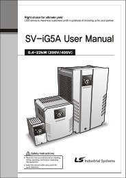
User Manual<br />
<strong>PROFIBUS</strong>-<strong>DP</strong><br />
<strong>Option</strong> <strong>board</strong><br />
<strong>SV</strong>-<strong>iS5</strong>,<strong>iP5A</strong>,<strong>iV5</strong> Series<br />
Read this manual carefully before using the <strong>PROFIBUS</strong>-<strong>DP</strong> <strong>Option</strong><br />
<strong>board</strong> and follow the instructions exactly.<br />
After reading this manual, keep it at handy for future reference.<br />
LS Industrial <strong>Systems</strong>
Thank you for purchase of LS Profibus-<strong>DP</strong> <strong>Option</strong> Board!<br />
SAFETY PRECAUTIONS<br />
• Always follow safety precautions to prevent accidents and potential hazards from occurring.<br />
• Safety precautions are classified into “WARNING” and “CAUTION” in this manual.<br />
WARNING<br />
CAUTION<br />
Indicates a potentially hazardous situation which, if not<br />
avoided, can result in serious injury or death.<br />
Indicates a potentially hazardous situation which, if not<br />
avoided, can result in minor to moderate injury, or serious<br />
damage to the product.<br />
• Throughout this manual we use the following two illustrations to make you aware of safety<br />
considerations:<br />
Identifies potential hazards.<br />
Read the message and follow the instructions carefully.<br />
Identifies shock hazards.<br />
Particular attention should be directed because dangerous voltage may be present.<br />
• Keep this manual at handy for quick reference.<br />
CAUTION<br />
• Do not touch the CMOS components unless the <strong>board</strong> is grounded.<br />
ESD can cause break down of CMOS components.<br />
• Do not change the communication cable with the inverter power is turned on.<br />
Otherwise, there is a danger of connecting error and damage to the <strong>board</strong>.<br />
• Make sure to precisely insert the connector of inverter and option <strong>board</strong><br />
Otherwise, there is a danger of connecting error and damage to the <strong>board</strong>.<br />
• Check the parameter unit when setting the parameters.<br />
Otherwise, there is a danger of connecting error and damage to the <strong>board</strong>.<br />
• Connect terminal resistor at the last connected option <strong>board</strong>.
1. INTRODUCTION<br />
By using a Profibus <strong>Option</strong> <strong>board</strong>, <strong>SV</strong>-<strong>iS5</strong>/<strong>iP5A</strong>/<strong>iV5</strong> inverters can be connected to a Profibus network.<br />
1.1. When you use the Profibus <strong>Option</strong> Card …<br />
• Drive can be controlled and monitored by the sequence program of the PLC or other master module.<br />
• With a single communication line, multi-units of drives can be operated simultaneously with each other,<br />
reducing the installation cost compared to that case of non-communication system set up. Also, simple<br />
wire installation can cut down installation and maintenance labor hours.<br />
• Able to use PLCs to control the drive and can be integrated with PC to simplify the Total Factory<br />
Automation.<br />
1.2. Kit Contents<br />
The option <strong>board</strong> kit consists of <strong>Option</strong> Board 1 pcs, Mounting pole 3 pcs, Installation Manual<br />
1.3. Profibus <strong>Option</strong> Board Specification<br />
1.3.1 Communication specification<br />
Subject<br />
Specification<br />
Device Type<br />
Profibus-<strong>DP</strong> Slave<br />
Auto Baud Rate Detect Supported<br />
Sync Mode<br />
Supported<br />
Freeze Mode<br />
Supported<br />
Max Input Length<br />
8 words<br />
Max Output Length<br />
8 words<br />
Max Data Length<br />
16 words<br />
Baud Rate Support<br />
9.6K, 19.2K, 93.75K, 187.5K, 500K, 1.5M, 3M, 6M, 12M<br />
Modular Station<br />
Supported<br />
Max Module 2<br />
1.3.2 Communication available distance<br />
Communication speed(bps) Max segment length Max extention distance<br />
9.6k ~ 187.5k 1000 m / 3278 feet 10000 m / 32786 feet<br />
500k 400 m / 1311 feet 4000 m / 13114 feet<br />
1.5M 200 m / 655 feet 2000 m / 6557 feet<br />
3M ~ 12M 100 m / 327 feet 1000 m / 3278 feet
2. Layout and Installation<br />
2.1 Layout<br />
Terminal resistor S/W<br />
LED D4<br />
Inverter interface<br />
connector<br />
ON<br />
OFF<br />
J1<br />
<strong>PROFIBUS</strong>-<strong>DP</strong> interface<br />
A1 B1 S1 A2 B2 S2<br />
LED<br />
D3<br />
D2<br />
D1<br />
Mounting poles<br />
Fig 1. Layout<br />
2.1.1 Status LED<br />
Interface LED with drive Active when the communication between drive and Profibus <strong>Option</strong> Module<br />
LED(D1)<br />
is operating correctly.<br />
Heart beat LED(D2) LED is ON with 1 sec period while option <strong>board</strong> has no problem it self.<br />
Error LED(D3)<br />
LED is ON with 1 sec period while it has different In/Out number of Master<br />
and Inverter..<br />
Profibus communication<br />
status LED(D4)<br />
Active when status of Profibus is operating correctly.<br />
* Please refer to “5. Troubleshooting” for further details.<br />
2.1.2 Communication Terminal<br />
A1 B1 S1 A2 B2 S2<br />
Pin No. A1 B1 S1 A2 B2 S2<br />
Receive/<br />
Receive/<br />
Receive/<br />
Receive/<br />
Description<br />
Transmit Data<br />
Transmit Data<br />
Shield<br />
Transmit Data<br />
Transmit Data<br />
Shield<br />
Plus<br />
Negative<br />
Plus<br />
Negative
2.1.3 Terminal resistor setting<br />
Connect inner terminal resistor by trrigering Switch J1 when it is used at terminal.<br />
ON OFF<br />
ON OFF<br />
J1 Case that connecting resistor<br />
J1<br />
Case that Not connecting resistor<br />
2.2 Installation<br />
2.2.1 Installing Profibus <strong>board</strong> on Inverter <strong>board</strong><br />
Fig 2. Installing <strong>SV</strong>-<strong>iS5</strong>/<strong>iP5A</strong> Profibus <strong>DP</strong> on Inverter <strong>board</strong><br />
Fig 3. Installing <strong>SV</strong>-<strong>iV5</strong> Profibus <strong>DP</strong> on Inverter <strong>board</strong>
2.3 Profibus <strong>DP</strong> Parameter Setting<br />
2.3.1 MAC ID(Media Access Control Identifier) Setting<br />
1. MAC ID(Media Access Control Identifier) has different unique value which can distinguishing the each<br />
Node in Profibus Network. Therefore, it is impossible to share at each different device.<br />
2. MAC ID is changable by Keypad.<br />
3. Default value is “1”. If any trouble in <strong>DP</strong>RAM communication between inverter and option card,<br />
default value is 127.<br />
Inverter Display Minimum Maximum Parameter Location<br />
<strong>SV</strong>-<strong>iS5</strong> COM Group, # 20<br />
<strong>SV</strong>-<strong>iP5A</strong> Profi MAC ID 1 127<br />
COM Group, # 20<br />
<strong>SV</strong>-<strong>iV5</strong><br />
EXT_09<br />
2.3.2 Setting the Number of output Data<br />
1. Setting the number of monitoring data<br />
Inverter Display Minimum Maximum Parameter Location<br />
<strong>SV</strong>-<strong>iS5</strong> COM Group, # 30<br />
<strong>SV</strong>-<strong>iP5A</strong> OutPut Num 1 8<br />
COM Group, # 30<br />
<strong>SV</strong>-<strong>iV5</strong><br />
EXT_10<br />
2.3.3 Setting the number of input data<br />
1. Setting the number of external command data<br />
Inverter Display Minimum Maximum Parameter Location<br />
<strong>SV</strong>-<strong>iS5</strong> COM Group, # 40<br />
<strong>SV</strong>-<strong>iP5A</strong> InPut Num 1 8<br />
COM Group, # 40<br />
<strong>SV</strong>-<strong>iV5</strong><br />
EXT_19<br />
2.3.4 Setting the addresses of output data<br />
1. Setting the addresses as many as the number of output data.<br />
Inverter Display Minimum Maximum Parameter Location<br />
<strong>SV</strong>-<strong>iS5</strong> 0000h FFFFh COM Group, # 30~38<br />
<strong>SV</strong>-<strong>iP5A</strong> OutPut 0~7 0000h FFFFh COM Group, # 31~38<br />
<strong>SV</strong>-<strong>iV5</strong><br />
0000h 7C3Bh EXT_11~18<br />
2.3.5 Setting the addresses of input data<br />
1. Setting the addresses as as many as the number of input data.<br />
Inverter Display Minimum Maximum Parameter Location<br />
<strong>SV</strong>-<strong>iS5</strong> 0000h FFFFh COM Group, # 41~48<br />
<strong>SV</strong>-<strong>iP5A</strong> InPut 0~7 0000h FFFFh COM Group, # 40~48<br />
<strong>SV</strong>-<strong>iV5</strong><br />
0000h 7C3Bh EXT_20~27
3 I/O Data Transmit/Receive<br />
Output data set by Keypad is transmitted to Profibus Master Module (PLC or PC) through Profibus <strong>Option</strong><br />
Module. On the contrary, input data is received from Profibus Master Module(PLC or PC) through Profibus<br />
<strong>Option</strong> Module.<br />
4 Operation<br />
4.1 When power-up or reset.<br />
• After self-testing, Heart beat LED(D2) blinks when no fault occurs . If any fault is detected, Heart beat<br />
LED(D2) is off or Error LED(D3) is turned on.<br />
• After trying to get correct configuration parameter (Station Address, Out data No, In Data No, Out Data<br />
Address1~8, In Data Address1~8 set by Keypad) by <strong>DP</strong>RAM with drive, configure profibus and start<br />
the communication. Interface LED(D1) blinks whenever communicating to drive.<br />
• Profibus communication status LED(D4) is deactivated when communication with Master starts as<br />
correct configuration.<br />
5 Troubleshooting<br />
LEDs (Profibus communication status LED, Interface LED with drive, Heart beat LED, Error LED) indicate<br />
the status of device and network.<br />
< Profibus communication status LED(D4) ><br />
LED Status Cause Help<br />
Misconnection with<br />
connector<br />
Check pin number of connector and connection of terminate<br />
resistor<br />
There is no MASTER<br />
in this network<br />
Check master status or master existence<br />
Off<br />
Off-<br />
Line<br />
Wrong address<br />
Check the address in Keypad is equal to that of LSIS Profibus<br />
<strong>Option</strong> Module using Configuration Tool, and unique number in<br />
network.<br />
Network Configuration<br />
problem<br />
Check the maximum length of segment.<br />
Check the numbers of node include repeater in segment.<br />
Number of node must be 32 or above in segment.<br />
Check the numbers of node include repeater in Network.<br />
Number of node must be 126 or above in network.<br />
On<br />
On-<br />
Line<br />
Network, address,<br />
Parameterization,<br />
Configuration is<br />
operating correctly.
Interface with drive LED ><br />
LED Status Cause Help<br />
Off<br />
<strong>DP</strong>RAM<br />
Interface<br />
error<br />
Interface between drive<br />
and <strong>DP</strong>RAM is not<br />
available.<br />
Check the power of drive.<br />
Check the fault status of drive.<br />
Check the connector to drive<br />
On Normal Operating correctly<br />
< Heart Beat LED ><br />
LED Status Cause Help<br />
Off<br />
<strong>Option</strong><br />
Module<br />
Operating of option<br />
Check the power of drive.<br />
error<br />
Module is not available<br />
Check the fault status of drive.<br />
Check the connector to drive<br />
Blink about<br />
1 sec period<br />
Normal Operating correctly<br />
< Error LED ><br />
LED Status Cause Help<br />
On<br />
<strong>Option</strong><br />
Module<br />
Operating of option<br />
error<br />
Module is not available.<br />
Check the fault status of drive.<br />
Check the connector to drive.<br />
Off Normal Operating correctly<br />
6 EDS file (Electronic Data Sheets)<br />
This is a file that contains drive parameter data. In order to control the parameter of <strong>SV</strong>-<strong>iS5</strong>/<strong>iP5A</strong>, the EDS<br />
file for <strong>iS5</strong>/<strong>iP5A</strong> drive must be installed (EDS file is downloadable at LSIS Homepage www.lsis.biz.)<br />
7 Parameter Code (Hex)<br />
Common Area: Area accessible regardless of inverter models, There are some address for<br />
special Inverter model. (Note1)<br />
Note1) The changed value in Common affects the current setting but returns to the previous setting when<br />
power is cycled or Inverter is reset. However, changing value is immediately reflected in other<br />
parameter groups even in the case of Reset or Power On/Off.<br />
7.1 <strong>SV</strong>-<strong>iS5</strong> Parameter Code<br />
7.1.1 Common area for <strong>SV</strong>- <strong>iS5</strong><br />
Parameter<br />
Address<br />
Parameter Name Unit Read/Write Data Value (Hex)<br />
0x0000 Drive model - R 4: <strong>SV</strong>-<strong>iS5</strong><br />
0x0001 Drive capacity - R<br />
0: 0.75 1:1.5 2:2.2 3: 3.7 4: 5.5<br />
5: 7.5 6: 11 7: 15 8: 18.5 9: 22 A:<br />
30 B:37 C:45 D: 55 E: 75 F: 90
Parameter<br />
Address<br />
Parameter Name Unit Read/Write Data Value (Hex)<br />
10: 110 11: 132 12: 160 13: 200<br />
14:220 15:280 16:375 (Unit : kW)<br />
0x0002 Drive Input Voltage - R 0: 220V 1: 440V<br />
0x0003 S/W Version - R 0100: Ver. 1.00, 0101: Ver 1.01<br />
0x0005 Frequency Reference 0.01Hz R/W<br />
0x0006 Run Command - R/W<br />
0x0007 Acceleration Time 0.1 sec R/W<br />
0x0008 Deceleration Time 0.1 sec R/W<br />
0x0009 Output Current 0.1 A R<br />
0x000A Output Frequency 0.01 Hz R<br />
0x000B Output Voltage 0.1 V R<br />
0x000C DC Link Voltage 0.1 V R<br />
0x000D Output Power 0.1 kW R<br />
0x000E Sequence Monitor - R<br />
0x000F Trip information - R<br />
0x0010 Input Terminal Status - R<br />
Bit 0: Stop<br />
Bit 1: Forward Run<br />
Bit 2: Reverse Run<br />
Bit 3: Fault Reset<br />
Bit 4: Emergency Stop<br />
BIT 0 : Stop<br />
BIT 1 : Forward Run<br />
BIT 2 : Reverse Run<br />
BIT 3 : Fault (Trip)<br />
BIT 4 : Accelerating<br />
BIT 5 : Decelerating<br />
BIT 6 : Output Frequency Arrival<br />
BIT 7 : DC Braking<br />
BIT 8 : Stopping<br />
BIT 9 :Not Available<br />
BIT 10 : BrakeOpen<br />
BIT 11: Forward Run Command<br />
BIT 12 : Reverse Run Command<br />
BIT 13 : Rem, Run/Stop<br />
BIT 14 : Rem, Freq. Cmd<br />
Bit 0:OCT1, Bit 1: OV, Bit 2: EXT-A Bit<br />
3: BX, Bit 4:OCT2, Bit 5: GF, Bit 6:<br />
OH,Bit 7: ETH, Bit 8: OLT, Bit 9: HWdiag,Bit10:EXT-B,Bit11:FO<br />
Bit12:OPT,Bit13:POBit,14:IOLT,<br />
Bit15:LV<br />
Bit 0: P1, Bit 1: P2, Bit 2: P3<br />
Bit 3: P4, Bit 4: P5, Bit 5: P6,<br />
Bit 6: RST, Bit 7: BX, Bit 8: JOG, Bit<br />
9: FX, Bit 10: RX
Parameter<br />
Address<br />
Parameter Name Unit Read/Write Data Value (Hex)<br />
0x0011<br />
Bit 0: Q1 (OC1) , Bit 1: Q2 (OC2)<br />
Output Terminal<br />
- R Bit 2: Q3 (OC3), Bit 3: AUX<br />
Status<br />
Bit 4: 30AC<br />
0x0012 V1 - R 0000h – FFC0h<br />
0x0013 V2 - R 0000h – FFC0h<br />
0x0014 I - R 0000h – FFC0h<br />
0x0015 RPM - R<br />
7.1.2 <strong>SV</strong>-<strong>iS5</strong> Function code<br />
< DRV Group ><br />
Address No. Parameter Default Max Min Unit<br />
5100 DRV #00 Cmd. freq 0 MaxFreq 0 0.01Hz<br />
5101 DRV #01 Acc. Time 100 6000 0 0.1sec<br />
5102 DRV #02 Dec. Time 200 6000 0 0.1sec<br />
5103 DRV #03 Drive mode 1 2 0<br />
5104 DRV #04 Freq. mode 0 4 0<br />
5105 DRV #05 Step freq - 1 1000 MaxFreq Start freq 0.01Hz<br />
5106 DRV #06 Step freq - 2 2000 MaxFreq Start freq 0.01Hz<br />
5107 DRV #07 Step freq - 3 3000 MaxFreq Start freq 0.01Hz<br />
5108 DRV #08 Current - - - 0.1A<br />
5109 DRV #09 Speed - - - 1rpm<br />
510A DRV #10 DC Link Voltage * - - V<br />
5110 DRV #16 Hz/Rpm Disp * - - Hz/Rpm<br />
< FU1 Group ><br />
Address No. Parameter Default Max Min Unit<br />
5203 FU1 #03 Run prohibit 0 2 0<br />
5205 FU1 #05 Acc. pattern 0 4 0<br />
5206 FU1 #06 Dec. pattern 0 4 0<br />
5207 FU1 #07 Stop mode 0 2 0<br />
5208 FU1 #08 DcBr freq. 500 6000 Start freq 0.01Hz<br />
5209 FU1 #09 DcBlk time 10 6000 0 0.01sec<br />
520A FU1 #10 DcBr value 50 200 0 %<br />
520B FU1 #11 DcBr time 10 600 0 0.1sec<br />
520C FU1 #12 DcSt value 50 200 0 %<br />
520D FU1 #13 DcSt time 0 600 0 0.1sec<br />
520E FU1 #14 PreExTime 10 600 0 0.1sec<br />
520F FU1 #15 Hold time 1000 10000 0 1msec
5210 FU1 #16 Flux Force 1000 5000 1000 0.1%<br />
5214 FU1 #20 Max freq. 6000 40000 4000 0.01Hz<br />
5215 FU1 #21 Base freq. 6000 Max freq 3000 0.01Hz<br />
5216 FU1 #22 Start freq. 50 6000 1 0.01Hz<br />
5217 FU1 #23 Freq limit 0 1 0<br />
5218 FU1 #24 F-limit Lo. 50 highFreq Start freq 0.01Hz<br />
5219 FU1 #25 F-limit Hi. 6000 Max freq lowFreq 0.01Hz<br />
521A FU1 #26 Torque boost 0 1 0<br />
521B FU1 #27 Fwd boost 20 150 0 0.1%<br />
521C FU1 #28 Rev boost 20 150 0 0.1%<br />
521D FU1 #29 V/F pattern 0 2 0<br />
521E FU1 #30 User freq. 1 1500 Max freq 0 0.01Hz<br />
521F FU1 #31 User volt. 1 25 100 0 %<br />
5220 FU1 #32 User freq. 2 3000 Max freq 0 0.01Hz<br />
5221 FU1 #33 User volt. 2 50 100 0 %<br />
5222 FU1 #34 User freq. 3 4500 Max freq 0 0.01Hz<br />
5223 FU1 #35 User volt. 3 75 100 0 %<br />
5224 FU1 #36 User freq. 4 6000 Max freq 0 0.01Hz<br />
5225 FU1 #37 User volt. 4 100 100 0 %<br />
5226 FU1 #38 Volt control 1000 1100 400 0.1%<br />
5227 FU1 #39 Energy save 0 30 0 %<br />
5232 FU1 #50 ETH select 0 1 0<br />
5233 FU1 #51 ETH 1min 180 200 ETH Cont %<br />
5234 FU1 #52 ETH Cont 100 150 50 %<br />
5235 FU1 #53 Motor type 0 1 0<br />
5236 FU1 #54 OL level 150 150 30 %<br />
5237 FU1 #55 OL time 100 300 0 0.1sec<br />
5238 FU1 #56 OLT select 1 1 0<br />
5239 FU1 #57 OLT level 180 200 30 %<br />
523A FU1 #58 OLT time 600 600 0 0.1sec<br />
523B FU1 #59 Stall prev. 0 7 0<br />
523C FU1 #60 Stall level 180 250 30 %<br />
< FU2 Group ><br />
Address No. Parameter Default Max Min Unit<br />
5307 FU2 #07 Dwell freq 500 Max freq Start freq 0.01Hz<br />
5308 FU1 #08 Dwell time 0 100 0 0.1sec<br />
530A FU2 #10 Jump freq 0 1 0<br />
530B FU2 #11 jump lo 1 1000 jump Hi 1 Start freq 0.01Hz
530C FU2 #12 jump Hi 1 1500 Max freq jump Lo 1 0.01Hz<br />
530D FU2 #13 jump lo 2 2000 jump Hi 2 Start freq 0.01Hz<br />
530E FU2 #14 jump Hi 2 2500 Max freq jump Lo 2 0.01Hz<br />
530F FU2 #15 jump lo 3 3000 jump Hi 3 Start freq 0.01Hz<br />
5310 FU2 #16 jump Hi 3 3500 Max freq jump Lo 3 0.01Hz<br />
5311 FU2 #17 Start Curve 40 100 1 %<br />
5312 FU2 #18 End Curve 40 100 1 %<br />
5313 FU2 #19 Trip select 0 3 0 BIT<br />
5314 FU2 #20 Power-on run 0 1 0<br />
5315 FU2 #21 RST restart 0 1 0<br />
5316 FU2 #22 Speed Search 0 15 0 BIT<br />
5317 FU2 #23 SS Sup-Curr 100 200 80<br />
5318 FU2 #24 SS P-gain 100 9999 0<br />
5319 FU2 #25 SS I-gain 1000 9999 0<br />
531A FU2 #26 Retry number 0 10 0<br />
531B FU2 #27 Retry delay 10 600 0 0.1sec<br />
531C FU2 #28 SS blk time 10 600 0 0.1sec<br />
531E FU2 #30 Motor select 0 9 0<br />
531F FU2 #31 Pole number 4 12 2<br />
5320 FU2 #32 Rated-Slip<br />
5321 FU2 #33 Rated-Curr<br />
5322 FU2 #34 Noload-Curr<br />
5323 FU2 #35 Motor Volt<br />
5324 FU2 #36 Efficiency<br />
(Note2)<br />
(Note2)<br />
(Note2)<br />
(Note3)<br />
(Note2)<br />
1000 0 0.01Hz<br />
2000 10 0.1A<br />
2000 5 0.1A<br />
460 180 V<br />
100 70 %<br />
5325 FU2 #37 Inertia rate 0 1 0<br />
5326 FU2 #38 Carrier freq 50 150 10 0.1kHZ<br />
5327 FU2 #39 Control mode 0 5 0<br />
5328 FU2 #40 Auto tuning 0 4 0<br />
5329 FU2 #41 Rs<br />
532A FU2 #42 Lsigma<br />
532B FU2 #43 Ls<br />
532C FU2 #44 Tr<br />
(Note4)<br />
(Note5)<br />
(Note6)<br />
(Note7)<br />
9999 0 0.001ohm<br />
9999 0 0.001mH<br />
9999 0 0.001mH<br />
5000 25 0.1msec<br />
532D FU2 #45 SL P-gain 1000 32767 0<br />
532E FU2 #46 SL I-gain 100 32767 0<br />
532F FU2 #47 proc PI mode 0 1 0<br />
5330 FU2 #48 PID F-gain 0 9999 0 0.1%<br />
5331 FU2 #49 Aux Ref Mode 0 5 0<br />
5332 FU2 #50 PID Out Dir 1 1 0<br />
5333 FU2 #51 PID F/B 0 2 0<br />
5334 FU2 #52 PID P-gain 3000 9999 0 0.1%
5335 FU2 #53 PID I-time 300 320 0 0.1sec<br />
5336 FU2 #54 PID D-time 0 9999 0 0.1msec<br />
5337 FU2 #55 PID limit-H 6000 Max freq 0 0.01Hz<br />
5338 FU2 #56 PID limit-L 0 Max freq 0 0.01Hz<br />
5339 FU2 #57 PID Out Inv 0 1 0<br />
533A FU2 #58 PID OutScale 1000 9999 1 0.1%<br />
533B FU2 #59 PID P2-gian 1000 9999 0 0.1%<br />
533C FU2 #60 P-gain Scale 1000 1000 0 0.1%<br />
5345 FU2 #69 Acc/Dec ch F 0 Max freq 0 0.01Hz<br />
5346 FU2 #70 Acc/Dec freq 0 1 0<br />
5347 FU2 #71 Time scale 1 2 0<br />
5348 FU2 #72 PowerOn disp 0 12 0<br />
5349 FU2 #73 User disp 0 2 0<br />
534A FU2 #74 RPM factor 100 1000 1 %<br />
534B FU2 #75 DB mode 1 2 0<br />
534C FU2 #76 DB %ED 10 30 0 %<br />
5351 FU2 #81 2nd Acc time 50 6000 0 0.1sec<br />
5352 FU2 #82 2nd Dec time 100 6000 0 0.1sec<br />
5353 FU2 #83 2nd BaseFreq 6000 Max freq 3000 0.01Hz<br />
5354 FU2 #84 2nd V/F 0 2 0<br />
5355 FU2 #85 2nd F-boost 20 150 0 0.1%<br />
5356 FU2 #86 2nd R-boost 20 150 0 0.1%<br />
5357 FU2 #87 2nd Stall 150 150 30 %<br />
5358 FU2 #88 2nd ETH 1min 150 200<br />
5359 FU2 #89 2nd ETH Cont. 100<br />
2nd ETH<br />
1min<br />
2nd ETH<br />
Cont<br />
%<br />
50 %<br />
535A FU2 #90 2nd R-Curr 36 2000 10 0.1A<br />
535D FU2 #93 Para. Init 0 8 0<br />
Note 2,3) It depends on Motor capacity and voltage.<br />
Note 4,5,6,7) It depends on motor capacity and Auto Tunning.<br />
< I/O 그룹 ><br />
Address No. Parameter Default Max Min Unit<br />
5401 I/O #01 V1 filter 10 9999 0 ms<br />
5402 I/O #02 V1 volt x1 0 V1 vort x2 0 0.01V<br />
5403<br />
I/O #03<br />
V1 freq y1<br />
/ V1 % y1<br />
0<br />
0<br />
Max freq<br />
1500<br />
0<br />
0<br />
0.01Hz<br />
0.1%<br />
5404 I/O #04 V1 volt x2 1000 1000 V1 volt x1 0.01V<br />
5405<br />
I/O #05<br />
V1 freq y2/ V1 % y2<br />
6000<br />
1500<br />
Max freq<br />
1500<br />
0<br />
0<br />
0.01Hz<br />
0.1%
5406 I/O #06 I filter 10 9999 0 ms<br />
5407 I/O #07 I curr x1 400 I curr x2 0 0.01mA<br />
5408 I/O #08 I freq y1 0 Max freq 0 0.01Hz<br />
5409 I/O #09 I curr x2 2000 2000 I curr x1 0.01mA<br />
540A I/O #10 I freq y2 6000 Max freq 0 0.01Hz<br />
540B I/O #11 Wire broken 0 2 0<br />
540C I/O #12 P1 define 0 42 0<br />
540D I/O #13 P2 define 1 42 0<br />
540E I/O #14 P3 define 2 42 0<br />
5411 I/O #17 Ti Filt Num 15 50 2<br />
5414 I/O #20 Jog freq 1000 Max freq Start freq 0.01Hz<br />
5415 I/O #21 Step freq - 4 4000 Max freq Start freq 0.01Hz<br />
5416 I/O #22 Step freq - 5 5000 Max freq Start freq 0.01Hz<br />
5417 I/O #23 Step freq - 6 4000 Max freq Start freq 0.01Hz<br />
5418 I/O #24 Step freq - 7 3000 Max freq Start freq 0.01Hz<br />
5419 I/O #25 Acc time– 1 200 6000 0 0.1sec<br />
541A I/O #26 Dec time – 1 200 6000 0 0.1sec<br />
541B I/O #27 Acc time – 2 300 6000 0 0.1sec<br />
541C I/O #28 Dec time – 2 300 6000 0 0.1sec<br />
541D I/O #29 Acc time – 3 400 6000 0 0.1sec<br />
541E I/O #30 Dec time - 3 400 6000 0 0.1sec<br />
541F I/O #31 Acc time – 4 500 6000 0 0.1sec<br />
5420 I/O #32 Dec time – 4 500 6000 0 0.1sec<br />
5421 I/O #33 Acc time – 5 400 6000 0 0.1sec<br />
5422 I/O #34 Dec time – 5 400 6000 0 0.1sec<br />
5423 I/O #35 Acc time – 6 300 6000 0 0.1sec<br />
5424 I/O #36 Dec time – 6 300 6000 0 0.1sec<br />
5425 I/O #37 Acc time – 7 200 6000 0 0.1sec<br />
5426 I/O #38 Dec time – 7 200 6000 0 0.1sec<br />
5428 I/O #40 FM mode 0 4 0<br />
5429 I/O #41 FM adjust 100 200 10 %<br />
542A I/O #42 FDT freq 3000 Max freq 0 0.01Hz<br />
542B I/O #43 FDT band 1000 Max freq 0 0.01Hz<br />
542C I/O #44 Aux mode 12 25 0<br />
542D I/O #45 Relay mode 2 7 0 BIT3<br />
542E I/O #46 Inv No. 1 31 1<br />
542F I/O #47 Baud rate 3 4 0<br />
5430 I/O #48 Lost command 0 2 0<br />
5431 I/O #49 Time out 10 1200 1 0.1sec<br />
< Note > Please contact us(www.LSIS.biz) requiring parameter addresses for Auto area
EXT Group ><br />
Address No. Parameter Default Max Min Unit<br />
5501 EXT #01 Sub B/D 0 8 0<br />
5502 EXT #02 P4 define 3 42 0<br />
5503 EXT #03 P5 define 4 42 0<br />
5504 EXT #04 P6 define 5 42 0<br />
5505 EXT #05 V2 mode 0 2 0<br />
5506 EXT #06 V2 filter 10 9999 0 msec<br />
5507 EXT #07 V2 volt x1 0 V2 volt x2 0 0.01V<br />
5508 EXT #08 V2 freq y1 0 Max freq 0 0.01Hz<br />
5509 EXT #09 V2 volt x2 1000 1000 V2 volt x1 0.01V<br />
550A EXT #10 V2 freq y2 6000 Max freq 0 0.01Hz<br />
550C EXT #12 F mode 0 2 0<br />
550F EXT #15 F pulse set 0 2 0<br />
5510 EXT #16 F pulse num 1024 4096 360<br />
5511 EXT #17 F filter 10 9999 0 msec<br />
5512 EXT #18 F pulse x1 0 F pulse x2 0 0.1kHz<br />
5513 EXT #19 F freq y1 0 Max freq 0 0.01Hz<br />
5514 EXT #20 F pulse x2 100 1000 F pulse x1 0.1kHz<br />
5515 EXT #21 F freq y2 6000 Max freq 0 0.01Hz<br />
5516 EXT #22 PG P-gain 3000 9999 0<br />
5517 EXT #23 PG I-gain 50 9999 0<br />
5518 EXT #24 PG Slip Freq 100 200 0 %<br />
5519 EXT #25 ASR P-Gain 1000 5000 100 0.1%<br />
551A EXT #26 ASR I-Gain 200 9999 10 msec<br />
551B EXT #27 Trq + Limit 180 200 0 %<br />
551C EXT #28 Trq - Limit 180 200 0 %<br />
551E EXT #30 Q1 define 0 23 0<br />
551F EXT #31 Q2 define 1 23 0<br />
5520 EXT #32 Q3 define 2 23 0<br />
5522 EXT #34 LM mode 1 3 0<br />
5523 EXT #35 LM adjust 100 200 10 %<br />
5528 EXT #40 AM1 mode 0 3 0<br />
5529 EXT #41 AM1 adjust 100 200 10 %<br />
552A EXT #42 AM2 mode 3 3 0<br />
552B EXT #43 AM2 adjust 100 200 10 %<br />
5532 EXT #50 Speed Limit 100 200 0 %<br />
5533 EXT #51 Speed Bias 100 200 0 %<br />
5534 EXT #52 Speed Gain 1 10 1
5535 EXT #53 Speed Dir 1 1 0<br />
5536 EXT #54 ZSD Level 200 12000 0 0.01Hz<br />
5537 EXT #55 ZSD Band 100 500 0 0.01Hz<br />
5538 EXT #56 TD Level 1000 1500 0 0.1%<br />
5539 EXT #57 TD Band 50 100 0 0.1%<br />
< COM Group ><br />
Address No. Parameter Default Max Min Unit<br />
5601 COM #01 Opt B/D 0 7 0<br />
5602 COM #02 Opt mode 0 3 0<br />
5603 COM #03 Opt version x.x<br />
5614 COM #20 Profi MAC ID 1 127 1<br />
561E COM #30 Output Num 3 8 0<br />
561F COM #31 Output 1 000A FFFF 0000 HEX<br />
5620 COM #32 Output 2 000E FFFF 0000 HEX<br />
5621 COM #33 Output 3 000F FFFF 0000 HEX<br />
5622 COM #34 Output 4 0000 FFFF 0000 HEX<br />
5623 COM #35 Output 5 0000 FFFF 0000 HEX<br />
5624 COM #36 Output 6 0000 FFFF 0000 HEX<br />
5625 COM #37 Output 7 0000 FFFF 0000 HEX<br />
5626 COM #38 Output 8 0000 FFFF 0000 HEX<br />
5628 COM #40 Input Num 2 8 0<br />
5629 COM #41 Input 1 0005 FFFF 0000 HEX<br />
562A COM #42 Input 2 0006 FFFF 0000 HEX<br />
562B COM #43 Input 3 0000 FFFF 0000 HEX<br />
562C COM #44 Input 4 0000 FFFF 0000 HEX<br />
562D COM #45 Input 5 0000 FFFF 0000 HEX<br />
562E COM #46 Input 6 0000 FFFF 0000 HEX<br />
562F COM #47 Input 7 0000 FFFF 0000 HEX<br />
5630 COM #48 Input 8 0000 FFFF 0000 HEX<br />
< APP Group ><br />
Address No. Parameter Default Max Min Unit<br />
5701 APP #01 APP mode 0 3 0<br />
5702 APP #02 Trv. Amp[%] 0 200 0 0.1%<br />
5703 APP #03 Trv. Scr 0 500 0 0.1%<br />
5704 APP #04 Trv Acc Time 20 6000 1 0.1sec<br />
5705 APP #05 Trv Dec Time 30 6000 1 0.1sec<br />
5706 APP #06 Trv Off Hi 0 200 0 0.1%<br />
5707 APP #07 Trv Off Lo 0 200 0 0.1%
5708 APP #08 Aux Mot Run 0 4 0<br />
5709 APP #09 Starting Aux 1 4 1<br />
570A APP #10 Auto Op Time 0 5940 0<br />
570B APP #11 Start freq1 4999 Max freq 0 0.01Hz<br />
570C APP #12 Start freq2 4999 Max freq 0 0.01Hz<br />
570D APP #13 Start freq3 4999 Max freq 0 0.01Hz<br />
570E APP #14 Start freq4 4999 Max freq 0 0.01Hz<br />
570F APP #15 Stop freq1 1500 Max freq 0 0.01Hz<br />
5710 APP #16 Stop freq2 1500 Max freq 0 0.01Hz<br />
5711 APP #17 Stop freq3 1500 Max freq 0 0.01Hz<br />
5712 APP #18 Stop freq4 1500 Max freq 0 0.01Hz<br />
5713 APP #19 Aux start DT 600 9999 0 0.1sec<br />
5714 APP #20 Aux stop DT 600 9999 0 0.1sec<br />
5715 APP #21 Nbr Aux’ 4 4 0<br />
5716 APP #22 Regul Bypass 0 1 0<br />
5717 APP #23 Sleep Delay 600 9999 0 0.1sec<br />
5718 APP #24 Sleep Freq 19 Max freq 0 0.01Hz<br />
5719 APP #25 WakeUp level 35 100 0 1%<br />
571A APP #26 AutoCh_Mode 1 2 0<br />
571B APP #27 AutoEx intv 4320 5940 0 0.1sec<br />
571C APP #28 AutoEx level 20 100 0 1%<br />
571D APP #29 Inter-lock 0 1 0<br />
571E APP #30 ActualF/P * 100 0 %<br />
571F APP #31 Actual B/kPa * 65472 0 Bar/Pa<br />
5720 APP #32 Scale Disp 1000 50000 0<br />
5721 APP #33 Draw mode 0 3 0<br />
5722 APP #34 DrawPerc 100 150 0 1%
7.1.3 <strong>SV</strong>-<strong>iS5</strong> Communication option setting<br />
COM-01 [Opt B/D]<br />
• Indicates <strong>Option</strong> <strong>board</strong>s installed. This value is automatically set when the <strong>board</strong>s are installed.<br />
COM-02 [ Opt Mode ]<br />
• Determines whether Run/Stop/Reference Frequency is set via Communication.<br />
Value Display Description<br />
0 None Disabled<br />
1 Command Run/Stop setting via Communication<br />
2 Freq Frequency setting via Communication<br />
3 Cmd + Freq Run/Stop/Reference Frequency via Communication<br />
COM-03 [ Opt Version ]<br />
• Displays version of <strong>Option</strong> Board.<br />
COM-20 [ Profi MAC ID ]<br />
• Sets MAC ID of profibus. The MAC ID must have a unique value in network.<br />
COM-30 [ Output Num ]<br />
• Sets the number of Read area address only.<br />
• Arrange COM #31~38 for using and set 1 to 8<br />
COM-40 [ Input Num ]<br />
• Sets the number of Write area address only.<br />
• Arrange COM #41~48 for using and set 1 to 8<br />
<br />
Address No Description Factory default Setting range<br />
5430 I/O #48<br />
Driving method when lost<br />
Communication Cmd<br />
0 (None)<br />
0 :None(Keep RUN)<br />
1 :Free Run/ Stop<br />
2 :Decel Stop<br />
Decision time for<br />
5431 I/O #49<br />
1.0s 1.0~120.0s<br />
Communication Cmd lost<br />
• In case that COM #02 1(Command) ~ 3 (Cmd + Freq), it drives by setting value of I/O #48 during<br />
the time of I/O #49 while lost communication command..
7.2 <strong>SV</strong>-<strong>iP5A</strong> Parameter Code<br />
7.2.1 Common area for <strong>SV</strong>- <strong>iP5A</strong><br />
Address Parameter Unit Unit R/W Data value<br />
0x0000 Inverter model R 9 : <strong>SV</strong>-<strong>iP5A</strong><br />
<strong>SV</strong>-<strong>iP5A</strong><br />
4: 5.5kW 5: 7.5kW 6: 11kW<br />
7: 15kW 8: 18.5kW 9: 22kW<br />
0x0001 Inverter capacity R<br />
A: 30kW B: 37kW C: 45kW<br />
D: 55kW E: 75kW F: 90kW<br />
10: 110kW 11: 132kW 12: 160kW<br />
13: 220kW 14: 280kW 15: 315kW<br />
16: 375kW 17: 450kW<br />
0x0002 Inverter Input Voltage R<br />
0 : 220V Class<br />
1 : 400V Class<br />
0x0003 S/W Version<br />
R<br />
(Ex) 0x0100 : Version 1.00<br />
0x0110 : Version 1.10<br />
0x0005 Frequency Reference 0.01 Hz R/W<br />
BIT 0: Stop (S)<br />
BIT 1: Forward run (F)<br />
BIT 2: Reverse run (R)<br />
R/W<br />
BIT 3: Fault reset (0->1)<br />
BIT 4: Emergency stop<br />
0x0006 Run Command<br />
BIT 5: Not used<br />
BIT 6, BIT 7: Run/Stop command source<br />
0(Terminal), 1(Keypad), 2(<strong>Option</strong>) 3: Int. 485<br />
BIT 8 ~12: Freq. reference<br />
0 ~ 16: Multi-step speed freq. (0, 2~16)<br />
R<br />
17 ~ 19: UpDown (Up, Down, UD Zero)<br />
20 ~ 21: RESERVED<br />
22 ~ 25: <strong>Ana</strong>log (V1, V1S, I, V1I)<br />
26: Pulse 27: Sub 28: Int. 485<br />
29: <strong>Option</strong>, 30: Jog, 31 : PID<br />
BIT 15: set when Network error<br />
0x0007 Acceleration Time 0.1 sec R/W<br />
0x0008 Deceleration Time 0.1 sec R/W<br />
0x0009 Output Current 0.1 A R<br />
0x000A Output Frequency 0.01 Hz R<br />
0x000B Output Voltage 0.1 V R<br />
0x000C DC Link voltage 0.1 V R<br />
0x000D Output power 0.1 kW R
Address Parameter Unit Unit R/W Data value<br />
0x000E Operating status of Inverter R<br />
0x000F Trip information<br />
R<br />
0x0010 Input terminal status<br />
R<br />
BIT 0: Stop<br />
BIT 1: Forward running<br />
BIT 2: Reverse running<br />
BIT 3: Fault (Trip)<br />
BIT 4: Accelerating<br />
BIT 5: Decelerating<br />
BIT 6: speed arrival<br />
BIT 7: DC Braking<br />
BIT 8: Stopping<br />
Bit 9: not Used<br />
BIT10: Brake Open<br />
BIT11: Forward run command<br />
BIT12: Reverse run command<br />
BIT13: REM. R/S (Int. 485, OPT)<br />
BIT14: REM. Freq. (Int. 485, OPT)<br />
BIT15: Not Used<br />
BIT 0 : OCT1<br />
BIT 1 : OV<br />
BIT 2 : EXT-A<br />
BIT 3 : BX<br />
BIT 4 : LV<br />
BIT 5 : RESERVE<br />
BIT 6 : GF(Ground Fault)<br />
BIT 6: OHT (Inverter overheat)<br />
BIT 7: ETH (Motor overheat)<br />
BIT 8: OLT (Overload trip)<br />
BIT10: HW-Diag<br />
BIT11: RESERVE<br />
BIT12: OCT2<br />
BIT13: OPT (<strong>Option</strong> error)<br />
BIT14 : PO (Phase Open)<br />
BIT15: IOLT<br />
BIT 0 : M1<br />
BIT 1 : M2<br />
BIT 2 : M3<br />
BIT 3 : M4<br />
BIT 4 : M5<br />
BIT 5 : M6<br />
BIT 6 : M7
Address Parameter Unit Unit R/W Data value<br />
BIT 7 : M8<br />
BIT 8 : P4<br />
`<br />
BIT 9 : P5<br />
BIT 10 : P6<br />
0x0011 Output terminal status<br />
R<br />
BIT11~15 : Not used<br />
BIT 0 : AUX1<br />
BIT 1 : AUX2<br />
BIT 2 : AUX3<br />
BIT 3 : AUX4<br />
BIT 4 : Q1 (OC1)<br />
BIT 5 : Q2 (OC2)<br />
BIT 6 : Q3 (OC3)<br />
BIT 7 : 30AC<br />
BIT8~15 : Not used<br />
0x0012 V1 0~10V R 0000h ~FFC0h<br />
0x0013 V2 0~10V R 0000h ~FFC0h<br />
0x0014 I 0~20mA R 0000h ~FFC0h<br />
0x0015 RPM R<br />
0x001A Unit display R 0 : Hz, 1 : Rpm<br />
0x001B Pole number R<br />
0x001C Custom Version R<br />
7.2.2 <strong>SV</strong>-<strong>iP5A</strong> Communication Setting<br />
< COM Group ><br />
Address NO. Description Default Maximum Minimum Unit<br />
9601 COM-01 Opt B/D 0 7 0<br />
9602 COM-02 Opt mode 0 3 0<br />
9603 COM-03 Opt Version<br />
0012 :<br />
Ver 1.2<br />
- - HEX<br />
9614 COM-20 Profi MAC ID 1 127 1<br />
961E COM-30 Output Num 3 8 0<br />
961F COM-31 Output 1 000A FFFF 0000 HEX<br />
9620 COM-32 Output 2 000E FFFF 0000 HEX<br />
9621 COM-33 Output 3 000F FFFF 0000 HEX<br />
9622 COM-34 Output 4 0000 FFFF 0000 HEX<br />
9623 COM-35 Output 5 0000 FFFF 0000 HEX<br />
9624 COM-36 Output 6 0000 FFFF 0000 HEX<br />
9625 COM-37 Output 7 0000 FFFF 0000 HEX<br />
9626 COM-38 Output 8 0000 FFFF 0000 HEX
Address NO. Description Default Maximum Minimum Unit<br />
9628 COM-40 Input Num 2 8 0<br />
9629 COM-41 Input 1 0005 FFFF 0000 HEX<br />
962A COM-42 Input 2 0006 FFFF 0000 HEX<br />
962B COM-43 Input 3 0000 FFFF 0000 HEX<br />
962C COM-44 Input 4 0000 FFFF 0000 HEX<br />
962D COM-45 Input 5 0000 FFFF 0000 HEX<br />
962F COM-46 Input 6 0000 FFFF 0000 HEX<br />
9630 COM-47 Input 7 0000 FFFF 0000 HEX<br />
9631 COM-48 Input 8 0000 FFFF 0000 HEX<br />
9643 COM-67 Comm Update 0 1 0<br />
COM-01 [Opt B/D]<br />
• Indicates <strong>Option</strong> <strong>board</strong>s installed. This value is automatically set when the <strong>board</strong>s are installed.<br />
COM-02 [ Opt Mode ]<br />
• Determines whether Run/Stop/Reference Frequency is set via Communication.<br />
Value Display Description<br />
0 None Disabled<br />
1 Command Run/Stop setting via Communication<br />
2 Freq Frequency setting via Communication<br />
3 Cmd + Freq Run/Stop/Reference Frequency via Communication<br />
COM-03 [ Opt Version ]<br />
• Displays version of <strong>Option</strong> Board.<br />
COM-20 [ Profi MAC ID ]<br />
• Sets MAC ID of profibus. The MAC ID must have a unique value in network.<br />
COM-30 [ Output Num ]<br />
• Sets the number of Read area address only.<br />
• Arrange COM #31~38 for using and set 1 to 8<br />
COM-40 [ Input Num ]<br />
• Sets the number of Write area address only.<br />
• Arrange COM #41~48 for using and set 1 to 8<br />
COM-67 [ Comm Update ]<br />
• In case of changing parameter concerned with communication, the changing contents use as<br />
updating.<br />
<br />
Address No Description Factory default Setting range<br />
945C I/O #92<br />
0 :None(Keep RUN)<br />
Driving method when lost<br />
0 (None) 1 :Free Run/ Stop<br />
Communication Cmd<br />
2 :Decel Stop<br />
945D I/O #93<br />
Decision time of<br />
Communication Cmd lost<br />
1.0s 1.0~120.0s<br />
• In case that COM #02 1(Command) ~ 3 (Cmd + Freq), it drives by setting value of I/O #48 during<br />
the time of I/O #49 while lost communication command.
7.3. <strong>SV</strong>-<strong>iV5</strong> Parameter Code<br />
7.3.1 Common area for <strong>SV</strong>-<strong>iV5</strong><br />
Description Unit R/W Data value<br />
0x0000 Inverter model - R 5: <strong>SV</strong>-<strong>iV5</strong><br />
<strong>SV</strong>-<strong>iV5</strong><br />
2:2.2 3:3.7 4:5.5 5:7.5<br />
6:11 7:15 8:18.5 9:22<br />
0x0001 Inverter capacity - R<br />
A:30 B:37 C:45 D:55<br />
E:75 F:90 10:110 11:132<br />
12:16<br />
0<br />
14:220<br />
(unit : kW)<br />
0x0002 Inverter input voltage - R 0: 220V Class 1: 440V Class<br />
0x0003 Version - R 0100h : Ver 1.00 0110h : Ver 1.10<br />
0x0005 Frequency Cmd 0.01Hz R/W Use 0x0502 instead of Not Used<br />
0x0006 Operation Cmd - R/W Use 0x0500 instead of Not Used<br />
0x0007 Accel Time 0.1 sec R/W <strong>SV</strong>-<strong>iV5</strong> : Used in Device Net Note6)<br />
0x0008 Decel Time 0.1 sec R/W <strong>SV</strong>-<strong>iV5</strong> : Used in Device Net Note6)<br />
0x0009 Output current 0.1 A R<br />
0x000A Output Frequency 0.01 Hz R <strong>SV</strong>-<strong>iV5</strong> :Used in Device Net Note7)<br />
0x000B Output Voltage 0.1 V R<br />
0x000C DC Link voltage 0.1 V R<br />
0x000D Output Power 0.1 kW R<br />
0x000E Operation Status - R<br />
Note8)<br />
Bit00 Stop<br />
Bit01 Forward Operation(FX)<br />
Bit02 Reverse Operation(RX)<br />
Bit03 Fault(Trip)<br />
Bit04 Under Accelerating<br />
Bit05 Under Decelerating<br />
Bit06 Speed arrival<br />
Bit07 Inverter Operation ready Note9)<br />
Bit08 Under Stop<br />
Bit09 Encoder direction Check Note10)<br />
Bit10 Under Torque Limit<br />
Bit11 Forward Cmd Note11)<br />
Bit12 Reverse Cmd Note11)<br />
Bit13 <strong>Option</strong> Run/Stop Cmd<br />
Bit14 <strong>Option</strong> Frequency Cmd<br />
Bit15 PID Enable Note12)
0x000F Trip Information - R<br />
0x0010 Input Terminal Information - R<br />
0x0011 Output Terminal Information - R<br />
0x0012 <strong>Ana</strong>log Input 1 - R<br />
Bit00 Over Current1(OCT U, V, W)<br />
Bit01<br />
Bit02<br />
Bit03<br />
Bit04<br />
Bit05<br />
Bit06<br />
Bit07<br />
Bit08<br />
Bit09<br />
Bit10<br />
Bit11<br />
Bit12<br />
Bit13<br />
Bit14<br />
Bit15<br />
Bit00<br />
Bit01<br />
Bit02<br />
Bit03<br />
Bit04<br />
Bit05<br />
Bit06<br />
Bit07<br />
Bit08<br />
Bit09<br />
Bit10<br />
Bit11<br />
Bit12<br />
Bit13<br />
Bit14<br />
Bit15<br />
Bit00<br />
Bit01<br />
Bit02<br />
Bit03<br />
Over Voltage(OV)<br />
Not Used<br />
BX<br />
Low Voltage(LV)<br />
Fuse Open(FO)<br />
Ground Fault(GF)<br />
Inverter Over Heat(IOH)<br />
E-Thermal(ETH)<br />
Over Load(OLT)<br />
HW-Diag<br />
External-B(EXT-B)<br />
Over Current2<br />
(Arm Short U, V, W)<br />
<strong>Option</strong> Error<br />
Encoder Error<br />
Inverter Over Load(IOLT)<br />
FX<br />
RX<br />
BX<br />
RST<br />
Not Used<br />
Not Used<br />
Not Used<br />
Not Used<br />
P1<br />
P2<br />
P3<br />
P4<br />
P5<br />
P6<br />
P7<br />
Not Used<br />
30A – 30C<br />
1A – 1B<br />
2A – 2B<br />
OC1 - EG<br />
Bit04~15 Not Used<br />
<strong>Ana</strong>log Input 1( User Manual Ai1)<br />
-100.0%(FC17h).~.100.0%(03E8h)
0x0013 <strong>Ana</strong>log Input 2 - R<br />
0x0014 <strong>Ana</strong>log Input 3 - R<br />
<strong>Ana</strong>log Input 2(User Manual Ai2)<br />
-100.0%(FC17h) ~ 100.0%(03E8h)<br />
<strong>Ana</strong>log Input 3(User Manual Ai3)<br />
-100.0%(FC17h) ~ 100.0%(03E8h)<br />
0x0015 RPM - R<br />
Reverse speed is conservative operation<br />
of 1 Note13)<br />
0x0017 Speed Cmd Hz R/W<br />
Note 14)<br />
<strong>SV</strong>-<strong>iV5</strong> : Used in Device Net<br />
0x001D Speed Cmd1 RPM R Target Speed Cmd<br />
0x001E Speed Cmd2 RPM R<br />
Note 15)<br />
Ramp Speed Cmd<br />
0x001F Speed control input Cmd RPM R<br />
Note 16)<br />
Speed controller Reference speed<br />
0x0020 Motor Speed RPM R<br />
Note 13)<br />
0x0021 Torque Reference 0.1% R<br />
Note 17)<br />
Torque Reference<br />
0x0022 Torque Feedback 0.1% R<br />
Note 18)<br />
Torque Feedback<br />
0x0023 No-load Current 0.1% R<br />
Percentage of PAR_26 Flux-Curr<br />
(Read Under driving : Refer to 0x050A<br />
Note 32) )<br />
0x0024 PID Reference 0.1% R<br />
Note 19)<br />
PID Reference<br />
0x0025 PID Feedback 0.1% R<br />
Note 20)<br />
PID Feedback<br />
0x0026 PID Output 0.1% R<br />
Note 21)<br />
PID Output<br />
0x0027 Inverter Temp deg R Inverter Temp<br />
0x0028 Line Speed 0.1% R<br />
Note 22)<br />
Motor speed when WEB Control<br />
0x0029 Diameter 0.1% R<br />
Calculated diameter when WEB Control<br />
Note 23)<br />
Note 24)<br />
0x002A Tension output 0.1% R Tension output when WEB Control<br />
0x002B Dancer Input 0.1% R<br />
Note 25)<br />
Dancer Input when WEB Control<br />
0x002C Taper Input 0.1% R<br />
Note 26)<br />
WEB Control 시 Taper Input Note 6) In case of acceleration/deceleration time they were used in the same address, as the addresses of<br />
0x0007 and 0x0008 are used by the other types (<strong>iS5</strong>, iG5…etc) in the device net. In case of <strong>SV</strong>-<strong>iV5</strong><br />
in fact, you may use acceleration/deceleration time of the addresses for 0x0503, 0x0504 in the rest<br />
except the device net.<br />
Note 7) Only when using the device net, Frequency(Hz) is displayed for the motor speed feedback during<br />
communication.<br />
Note 8) Negative output is calculated in 2's complement. For the calculation method, please refer to Note 17.<br />
Note 9) It indicates the state where the inverter can be operated without trip. In this case, it indicates the all<br />
the states during operation, before and after operation as ‘1’.<br />
Note 10) It indicates each state as follow; Stop (bit 0=‘1’) as ‘0’, Rotating in Forward Direction during<br />
Operation as ‘1’, Rotating in Reverse Direction during Operation as ‘0’.<br />
In case of connection error, it indicates as follows; Rotating in Forward Direction during Operation<br />
as ‘0’, Rotating in Reverse Direction during Operation as ‘1’..<br />
Note 11) Relationships between Bit10 Forward Direction Command / Bit11 Reverse Direction Command,<br />
and Bit01 Forward Direction Operation (FX) / Bit02 Reverse Direction Operation (RX) are as<br />
follows:<br />
Bit10 and Bit11 show current operation command information, while Bit01 and Bit02 show current<br />
operation state. For example, in case of inputting stop command during forward direction<br />
operation, Bit11 forward direction command becomes ‘0’, but Bit01 forward direction operation (FX)<br />
becomes ‘1’ during deceleration and ‘0’ after stop mode.<br />
For the other example, in case of inputting reverse direction operation command during forward<br />
direction 1800 RPM operation, it conducts deceleration at 1,800 RPM and Bit11 Reverse Direction
Command is remained ‘1’ and Bit01 Forward Direction operation (FX) being ‘1’ until the motor rotating<br />
direction will be changed.<br />
Note 12) In case CON_20 Proc PID Enb(0x7514) is set to Enable(‘1’), it shows ‘1’ during operation<br />
(bit13=‘1’). While showing ‘0’ during STOP mode.<br />
Note 13) In case of <strong>SV</strong>-<strong>iV5</strong>, positive direction speed and negative direction speed are shown. Positive<br />
direction speed is displayed in 0708h at 1800RPM, representing 1800 when expressed in decimal<br />
number. In this case you may read it as it is. Negative direction speed is displayed, for example,<br />
‘F8F7h at -1800RPM’ where the most significant bit is expressed in ‘F’ letter, which represents the<br />
negative number as 1’s complement notation. Therefore the absolute value is calculated as follow;<br />
(FFFFh – F8F7h) (10) = 0708h (10) = 1800<br />
Then,–1800RPM comes out after result of adding negative sign (-) to this absolute value.<br />
The formula to calculate the speed in negative form can be expressed as follow;<br />
Speed(RPM) = (FFFFh – FXXXh (Minus Speed Data Obtained)) (10) × (-1)<br />
Note 14) Speed command is instructed in Hz during device net communication.<br />
Note 15) This is the PostRamp Ref value verified during operation mode. Speed is expressed in the<br />
absolute value.<br />
Note 16) This is the PreRamp Ref value verified during operation mode. Speed is indicated divided by<br />
notations. Please refer to (Note 13).<br />
Note 17) This is the Torque Ref value of DIS_01 verified during operation mode. As it generates the minus<br />
torque value during reverse direction operation, please calculate it in 2’s complement.<br />
Ex) If it is read FE0Ch, calculate as follow;<br />
Torque (%)=(FFFFh-FE0Ch + 0001h) (10) × (-1)<br />
=(01F3h + 0001h) (10) × (-1)<br />
=(01F4h) (10) × (-1)<br />
=-500<br />
As the unit is 0.1%, it becomes –50%.<br />
Accordingly the formula for calculation is as follow;<br />
Torque(%) = (FFFFh – FXXXh (Minus Torque Data Obtained) + 0001h) (10) × (-1)<br />
Note 18) This is Tq on the basic display screen during operation mode. For the calculation method, please<br />
refer to (Note 17).<br />
Note 19) When CON_20 Proc PID Enb is set to Enable, it reads and stores the value of 0x050B PID<br />
input command during operation mode. In this case, this can be verified from the process PID<br />
command value from DIS_04 Process PID output controller. As the value of 0x050B PID input<br />
command is read and stored during operation mode only, the previous command value can be<br />
found through 0x0024 PID reference value even if 0x050B PID input command value was changed<br />
during STOP mode. In this case, the value other than the process PID command value of DIS_04 is<br />
stored. In case it starts operation, it reads the value from 0x050B again, and then stores the same<br />
value as the process PID command value of DIS_04.<br />
Note 20) In case CON_20 Proc PID Enb is set to Enable, it is the Process PID F/B value of DIS_04 Process<br />
PID output controller verified during operation mode.<br />
Note 21) In case CON_20 Proc PID Enb is set to Enable, it is the process PID output value of DIS_04
process PID output controller verified during operation mode.<br />
Note 22) Line Speed means the value of max. line speed expressed in % during WEB control.<br />
Note 23) Tension output means the total sum of tension outputs including WEB_19 Tension Input, <strong>Ana</strong>log<br />
Input, 0x0511 Tension Input Command during tension control mode with load cell used, where<br />
Taper, Stall and Boost are taken into account, that is, the final reference of PID control during<br />
tension control mode.<br />
Note 24) These are DIS_01 Diameter and WEB_01 Diameter.<br />
Note 23) These are DIS_01 Diameter and WEB_01 Diameter.<br />
Note 24) Tension output means the total sum of tension inputs including WEB_19 Tension Input, <strong>Ana</strong>log<br />
Input, 0x0511 Tension Input Command during tension control mode with load cell used, where<br />
Taper, Stall and Boost are taken into account, that is, the final reference of PID control during<br />
tension control mode. Negative number is calculated in 2’s compliment.<br />
Note 25) Dancer Input is the sum of WEB_29 Dancer Pos, <strong>Ana</strong>log Input and 0x0512 Dancer Input during<br />
dancer control mode, that is, the final reference of PID control during dancer control mode.<br />
Negative number is calculated in 2’s compliment.<br />
Note 26) Taper Input is the sum of WEB_21 Taper Input, <strong>Ana</strong>log Input and 0x0514 Taper Input when taper<br />
function is used, that is, the number of final taper. Negative number is calculated in 2’s<br />
compliment.<br />
7.3.2 Region : <strong>SV</strong>-<strong>iV5</strong> Communication Command region<br />
Address Description Unit R/W Data value<br />
0x0500 Input terminal Cmd Note 27) - R/W<br />
0x0501 Output terminal Cmd Note 28) - R/W<br />
Bit00<br />
Bit01<br />
Bit02<br />
Bit03<br />
Bit04<br />
Bit05<br />
Bit06<br />
Bit07<br />
Bit08<br />
Bit09<br />
Bit10<br />
Bit11<br />
Bit12<br />
Bit13<br />
Bit14<br />
Bit15<br />
Bit00<br />
Bit01<br />
Bit02<br />
Stop<br />
FX<br />
RX<br />
RST<br />
BX<br />
Not Used<br />
Not Used<br />
Not Used<br />
P1<br />
P2<br />
P3<br />
P4<br />
P5<br />
P6<br />
P7<br />
Not Used<br />
1A – 1B<br />
2A – 2B<br />
OC1 – EG
Bit03~15<br />
Not Used<br />
0x0502 Speed Cmd 0.1RPM R/W<br />
Speed Cmd FUN_02 is <strong>Option</strong>(DIS_01<br />
Note 29)<br />
PreRamp Ref)<br />
0x0503 Accel time 0.1sec R/W<br />
Note 30)<br />
Set Main Accel time<br />
0x0504 Decel time 0.1sec R/W<br />
Note 30)<br />
Set Main Decel time<br />
0x0505 Torque Cmd 0.1% R/W<br />
Torque Cmd when CON_26 is <strong>Option</strong><br />
Note 31)<br />
0x0506 Forward torque limit 0.1% R/W Forward torque limit<br />
Note 32)<br />
Note 32)<br />
0x0507 Reverse torque limit 0.1% R/W Reverse torque limit<br />
Note 32)<br />
0x0508 Regeneration torque limit 0.1% R/W Regeneration torque limit<br />
Note 33)<br />
0x0509 Torque bias 0.1% R/W Torque bias<br />
Note 34)<br />
0x050A No-load current Cmd 0.1% R/W No-load current Cmd<br />
Note 35)<br />
0x050B PID input Cmd 0.1% R/W PID input Cmd<br />
Note 36)<br />
0x050C Draw input Cmd 0.1% R/W Draw input Cmd<br />
Note 37)<br />
0x050D Line Speed Cmd 01.% R/W Line Speed Cmd<br />
Note 38)<br />
0x050E WEB Accel Time 0.01sec R/W Accel Time When WEB Control<br />
0x050F WEB Decel Time 0.01sec R/W Decel Time When WEB Control<br />
Note 39)<br />
0x0510 Diameter Preset 0.1% R/W Diameter Preset<br />
Note 40)<br />
0x0511 Tension input Cmd 0.1% R/W Tension input Cmd<br />
Note 41)<br />
0x0512 Dancer input Cmd 0.1% R/W Dancer input Cmd<br />
Note 42)<br />
0x0513 Tension Feedback 0.1% R/W Tension Feedback<br />
Note 43)<br />
0x0514 Taper input Cmd 0.1% R/W Taper input Cmd<br />
0x0515 WEB PID P1 Gain 0.1% R/W<br />
Note 44)<br />
WEB PID P1 Gain set<br />
0x0516 WEB PID I1 Gain 0.1sec R/W<br />
Note 44)<br />
WEB PID I1 Gain set<br />
0x0517 WEB PID D Gain 0.1% R/W<br />
Note 44)<br />
WEB PID D Gain set<br />
0x0518<br />
WEB PID Rewind<br />
WEB PID Rewind Output Gain set<br />
0.1% R/W Note 44)<br />
0x0519<br />
Output Gain<br />
WEB PID Unwind<br />
Output Gain<br />
0.1% R/W<br />
0x051A WEB Jog Accel Time 0.1sec R/W<br />
WEB PID Unwind Output Gain set<br />
Note 44)<br />
Note 38)<br />
WEB Jog Accel Time set<br />
Note 38)<br />
0x051B WEB Jog Decel Time 0.1sec R/W WEB Jog Decel Time set<br />
Note 38)<br />
Note 27) It is possible to RUN and Multi-Function input Cmd by Communication. Note that If you try to use<br />
Multi-Function input Cmd(P1 ~P7), it must be defined that Multi-Function Input of DIO_01 ~<br />
DIO_07.<br />
Note 28) If you try to output terminal Cmd, Set the corresponding terminal into “Not Used” among the multifunction<br />
output terminals(DIO_41 ~ DIO_43).<br />
Note 29) As Input value, positive is available only and DIS_01 PreRamp Ref is changed whether it is<br />
positive or negative according to RUN direction. Max value is limited by FUN_04 Max Speed.<br />
Ex) FUN_04 Max Speed = 1800RPM이면, 단위가 0.1RPM이므로 18000 -> 4650h<br />
Note 30) 0x0503 Acc Time is saved at FUN_40 Acc Time-1(0x7428).<br />
FUN▶ Acc Time-1<br />
40 10.00 sec<br />
In case that the unit of FUN_40 Acc Time-1 is 0.01sec as like<br />
left figure, the set range of 0x0503 is 0.0sec(0000h) ~
599.9sec(176Fh).<br />
In order to set over 600sec, set FUN_40 Acc Time-1 to 600.0sec<br />
FUN▶ Acc Time-1<br />
and changes the unit into 0.1sec. the set range of 0x0503 is<br />
40 600.0 sec<br />
600.0sec(1770h) ~ 6000.0sec(EA60h) in this case.<br />
FUN_40 activates writing action when new value is inserted in 0x0503. FUN_40 is saved and it is<br />
possible to read at 0x0503.<br />
0x0504 Dec time and FUN_41 Dec Time-1(0x7429) have same relation and possible to input Dec<br />
time by same manner with setting input range of 0x0504.<br />
Note 31) Torque Cmd, CON_01 is “Torque”, CON_26 is set to “<strong>Option</strong>” and can be settable when driving.<br />
Note 32) Only when CON_28 Trq Lmt Src is set to <strong>Option</strong> (Opt Opt Opt), torque limits can be set through<br />
communication. You can verify the value from DIS_01 PosTrq Limit, NegTrq Limit, RegTrq Limit .<br />
Note 33) If CON_32 Trq Bias Src is set to <strong>Option</strong>, you can verify from DIS_01 Torque Bias.<br />
Note 34) Unloaded current command can be commanded in the value set in PAR_26 in % through<br />
communication. In this case, the value set in PAR_26 means 100%. The value equal to or less than<br />
100% can be set. The value input is DIS_01 Flux Ref that can be verified during operation mode.<br />
Note 35) This can be verified from DIS_04 Process PID controller. Feedback and output can be verified<br />
during operation mode.<br />
Note 36) Only in case of giving the value through analog input or communication after setting CON_22 to a<br />
certain value, draw function can be used. In this case, communication means to replace the analog<br />
input value with communication, not to change the draw of CON_22. Accordingly it cannot be<br />
identified from the loader, but from the value of address changed.<br />
Note 37) When commanding the line speed through communication, FUN_02 Spd Ref Sel should be set to<br />
Line SPD Opt. In this case, the % value for the maximum line speed is input. For example, Max.<br />
line speed is 100[m/m], the line speed at the time of 100% Input is 100[m/m]. This can be verified<br />
from DIS_01 Line SPD CMD.<br />
Note 38) When WEB_11 AccDecWeb is set to “No” during WEB control mode, acceleration/deceleration<br />
time is operated depending on the acceleration/deceleration time of FUN_40 and FUN_41. If<br />
WEB_11 AccDecWeb is set to “Yes”, the acceleration/deceleration time of FUN_40 and FUN_41 is<br />
disregarded, and it is operated based on the setting of WEB acceleration/deceleration time. If<br />
WEB_56 JogTime Sel is set to “No”, acceleration/deceleration time of jog speed is operated based<br />
on the acceleration/deceleration time of FUN_40 and FUN_41. In case of setting WEB_56 JogTime<br />
Sel to “Yes”, the acceleration/deceleration time of FUN_40 and FUN_41 is disregarded. Jog<br />
operation is conducted by the setting of WEB Jog acceleration/deceleration time. WEB<br />
acceleration/deceleration time is stored in WEB_12 AccTimeWeb(0x7C0C), WEB_13<br />
DecTimeWeb(0x7C0D) respectively, and the characteristics during Write Operation mode are same<br />
as 0x0503 and FUN_40 Acc Time-1 in (Note 30). Jog acceleration/deceleration time is stored in<br />
WEB_57 JogAcc Time(0x7C39) and WEB_58 JogDec Time (0x7C3A) respectively, and for the<br />
characteristics during Write Operation mode, please refer to (Note 30) same as WEB<br />
acceleration/deceleration time.<br />
Note 39) This is the diameter initialization through communication. When setting one of DIO_01~07 to Dia<br />
Preset with power ON, you can conduct initialization. Setting range is WEB_10 Min Diameter ~
100.0%(03E8h).<br />
This can be verified from WEB_01 Diameter.<br />
Note 40) Tension input command means the tension input carried out through communication when load<br />
cell is used.<br />
When WEB_28 PIDRef Sel is set to “Taper Out”, it can be verified from Process PID Command value<br />
of IS_04 Process PID output controller during operation mode. In this case, the process PID<br />
command value can be influenced by the setting of (Note 26) Taper Input Value.<br />
Input range is -100.0% (FC17h) ~ 100.0% (03E8h).<br />
Note 41) Dancer input command means the dancer inputs carried out through communication when dancer<br />
is used.<br />
When WEB_28 PIDRef Sel is set to “Dancer Pos”, it can be verified from Process PID command<br />
value of DIS_04 Process PID output controller during operation mode.<br />
In this case, the process PID command value is the sum of WEB_29 dancer Pos, analog input and<br />
communication command value.<br />
Input range is -100.0%(FC17h) ~ 100.0%(03E8h).<br />
Note 42) In case of conducting tension feedback through communication, WEB_47 PID F/B Src should be<br />
set to “<strong>Option</strong>”. It can be verified from Process PID F/B value of DIS_04 Process PID Output<br />
controller. The input range is -150.0%(FA23h) ~ 150.0%(05DCh).<br />
To conduct tension feedback in analog, you should set to “<strong>Ana</strong>log” . If set to ““None”, tension<br />
feedback becomes 0. If tension feedback set to “<strong>Option</strong>”, the communication cycle should be done<br />
in 10[ms] or less.<br />
In case of the warper, it requires the tension control mode using the encoder, where the encoder<br />
pulse should be counted to use it as tension feedback. In this case, the inverter has no function<br />
of counting the pulse number, and therefore PLC counts the Encoder Pulse, calculates it into<br />
speed, converts it into %, and finally it should be communicated as tension feedback. For<br />
example, Max. Line Speed = 100[m/m], Gear Ratio = 1,<br />
When assuming that, Diameter = 100[mm], Encoder Pulse = 1024, Communication Cycle 10[ms],<br />
The formula will be expressed as follow;<br />
LineSpeed 100<br />
Speed =<br />
= = 318.3 [ rpm]<br />
Diameter × π 0.1×<br />
π<br />
1024 1<br />
318 .3 × × = 54.32 will be the maximum pulse number that is received at every<br />
60 100<br />
10[ms]..<br />
Address 0x050D ~ 0x051B can be communicated only when CON_02 Application is set to “ WEB<br />
Control”.<br />
Note 43) Taper input command means the taper inputs carried out through communication. When having<br />
the other value than ‘None’ of WEB_20 Taper Type, it is added to the taper inputs carried out<br />
through WEB_21 Taper Input and <strong>Ana</strong>log input, and then the final tapers are determined. When<br />
inputting the negative number, you may input it in 2’s complement.<br />
Input Range is -100.0%(FC17h) ~ 100.0%(03E8h).<br />
Note 44) The value of 0x0515~0x0519 is stored in WEB_30 ProcPID Kp1(0x7C1E), WEB_32 ProcPID
Ki1(0x7C20), WEB_37 ProcPID Kd(0x7C25), WEB_42 PIDOGainRe(0x7C2A) and<br />
WEB_43PIDOGainUn respectively. For the characteristics when the equal value is repeatedly<br />
input, please refer to (Note 30).<br />
When inputting the negative number in 0x0518 and 0x0519, you may input it in 2’s compliment.<br />
Input range is -250.0%(F63Ch) ~ 250.0%(09C4h).<br />
7.3.3 <strong>SV</strong>-<strong>iV5</strong> Communication option setting<br />
<br />
Address No Description Set value<br />
7401 FUN_01 Selection of Run/Stop Set by 3 (<strong>Option</strong>)<br />
7402 FUN_02<br />
Selection of Speed Cmd<br />
Selection of Line Speed Cmd<br />
Set by 3 (<strong>Option</strong>)<br />
Ser by 7 (Line SPD Opt)<br />
• The set of Run/Speed Cmd in option through communication is decided by FUN_01, 02.<br />
* RUN Cmd by option uses 0x0500 of Reference Data region.<br />
* Speed Cmd by option uses 0x0502 of Reference Data region.<br />
* Line Speed Cmd by option uses 0x050D of Reference Data region.<br />
<br />
Address No Description Default Setting Range<br />
7261 DIO_97<br />
Operation when lost<br />
Communication Cmd<br />
0 (None)<br />
0 (None: Keep RUN)<br />
1 (Free Run/Stop)<br />
2 (Decel Stop)<br />
Decision time for<br />
7262 DIO_98<br />
1.0sec 1.0~30.0sec<br />
Communication Cmd lost<br />
• In case that FUN_01 is 3(<strong>Option</strong>) or FUN_02 is 3 (<strong>Option</strong>), it drives by the setting value of DIO_97<br />
during the time of DIO_98 while lost communication command.<br />
< EXT Group ><br />
Address No Description Default Max Min Unit<br />
7601 EXT_01 Opt B/D 0 7 0<br />
7602 EXT_02 Opt Version 0022 : Ver 2.2 - - HEX<br />
7609 EXT_09 Profi MAC ID 1 127 1<br />
760A EXT_10 Output Num 3 8 0<br />
760B EXT_11 Output 1 0020 7C3B 0000 HEX<br />
760C EXT_12 Output 2 000E 7C3B 0000 HEX<br />
760D EXT_13 Output 3 000F 7C3B 0000 HEX<br />
760E EXT_14 Output 4 - 7C3B 0000 HEX<br />
760F EXT_15 Output 5 - 7C3B 0000 HEX<br />
7610 EXT_16 Output 6 - 7C3B 0000 HEX<br />
7611 EXT_17 Output 7 - 7C3B 0000 HEX<br />
7612 EXT_18 Output 8 - 7C3B 0000 HEX
7613 EXT_19 Input Num 2 8 0<br />
7614 EXT_20 Input 1 0502 7C3B 0000 HEX<br />
7615 EXT_21 Input 2 0500 7C3B 0000 HEX<br />
7616 EXT_22 Input 3 - 7C3B 0000 HEX<br />
7617 EXT_23 Input 4 - 7C3B 0000 HEX<br />
7618 EXT_24 Input 5 - 7C3B 0000 HEX<br />
7619 EXT_25 Input 6 - 7C3B 0000 HEX<br />
761A EXT_26 Input 7 - 7C3B 0000 HEX<br />
761B EXT_27 Input 8 - 7C3B 0000 HEX<br />
COM-01 [Opt B/D]<br />
• Indicates <strong>Option</strong> <strong>board</strong>s installed. This value is automatically set when the <strong>board</strong>s are installed.<br />
COM-02 [ Opt Version ]<br />
• Displays version of <strong>Option</strong> Board.<br />
COM-09 [ Profi MAC ID ]<br />
• Sets MAC ID of profibus. The MAC ID must have a unique value in network.<br />
COM-10 [ Output Num ]<br />
• Sets the number of Read area address only.<br />
• Arrange EXT #11~18 for using and set 1 ~ 8<br />
COM-19 [ Input Num ]<br />
• Sets the number of Write area address only.<br />
• Arrange EXT #20~27 for using and set 1 ~ 8