Quattro ERV Installation Manual (07918 rev. C):Constructo ... - Venmar
Quattro ERV Installation Manual (07918 rev. C):Constructo ... - Venmar
Quattro ERV Installation Manual (07918 rev. C):Constructo ... - Venmar

Create successful ePaper yourself
Turn your PDF publications into a flip-book with our unique Google optimized e-Paper software.
5. INSTALLATION (CONT’D)<br />
5.2 PLANNING THE DUCTWORK<br />
a) Follow the instructions in Section 5.3 to determine the appropriate duct diameters for your system.<br />
b) Keep it simple. Plan for a minimum number of bends and joints. Keep the length of insulated duct to a minimum.<br />
c) Do not use wall cavities as ducts. Do not use branch lines smaller than 4” (102 mm) Ø.<br />
d) Do not ventilate crawl spaces or cold rooms. Do not attempt to recover the exhaust air from a dryer or a range hood. This would<br />
cause clogging of the recovery core. Use sheet metal for the kitchen exhaust duct.<br />
e) Be sure to plan for at least one exhaust register on the highest lived-in level of the house if it has 2 floors or more.<br />
5.3 CALCULATING THE DUCT SIZE<br />
Use the table below to ensure that the ducts you intend to install will be carrying air flows at or under the recommended values.<br />
Avoid installing ducts that will have to carry air flows near the maximum values and never install a duct if its air flow exceeds<br />
the maximum value.<br />
Duct Recommended Maximum<br />
Diameter Air Flow Air Flow<br />
4” (102 mm) 40 cfm 19 l/s 68 m³/h 60 cfm 28 l/s 102 m³/h<br />
5” (127 mm) 75 cfm 35 l/s 127 m³/h 110 cfm 52 l/s 187 m³/h<br />
6” (152 mm) 120 cfm 57 l/s 204 m³/h 180 cfm 85 l/s 306 m³/h<br />
7” (178 mm) 185 cfm 87 l/s 314 m³/h 270 cfm 127 l/s 459 m³/h<br />
8” (203 mm) 260 cfm 123 l/s 442 m³/h 380 cfm 179 l/s 645 m³/h<br />
END<br />
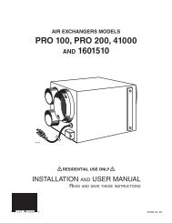
BRANCHES<br />
5" Ø<br />
70 CFM<br />
NOTE: Examples 5.3.1 and 5.3.2 use imperial measures.<br />
The same calculation applies to metric measures.<br />
5.3.1 Example of calculation:<br />
Problem: My installation requires two exhaust registers (one for the kitchen, one for the bathroom). I will connect these registers<br />
to a main duct which will connect to the unit (high speed performance value of 140 cfm). What size of duct should I use for the<br />
main exhaust duct and for the two end branches leading to the registers? (See Figure 7.)<br />
Solution: Simplified method. (For a more detailed method of calculating duct size refer to the ASHRAE or HRAI HANDBOOK).<br />
Main duct: Table above indicates a 6” Ø duct: recommended air flow: 120 cfm; maximum air flow: 180 cfm. The high speed air<br />
flow of 140 cfm is close enough to the recommended value (120) and far enough from the maximum value (180). Therefore a<br />
6” Ø duct or larger is an appropriate choice for the main exhaust duct.<br />
End branches: Each end branch will have to transport air flow of 70 cfm (140 divided by 2). Table above indicates a 5” Ø duct :<br />
recommended air flow : 75 cfm; maximum air flow : 110 cfm. The high speed air flow of 70 cfm is close enough to the<br />
recommended value (75) and far enough from the maximum value (110). Therefore, a 5” Ø duct or larger is an appropriate choice<br />
for the 2 end branches.<br />
NOTE : A 4” Ø duct would have been too small because the maximum acceptable value for a 4” Ø duct is 60 cfm.<br />
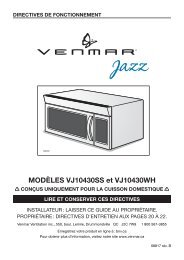
5.3.2 Example of a design for a fully ducted system for a unit having 222 cfm high speed performance (See Figure 8).<br />
VI0003<br />
FIGURE 7<br />
MAIN BRANCH<br />
6" Ø 140 CFM<br />
5”<br />
5” Ø<br />
65 CFM<br />
6” Ø<br />
129 CFM<br />
6” Ø<br />
93 CFM<br />
5” Ø<br />
64 CFM<br />
6”<br />
4”<br />
4”<br />
4” Ø<br />
42 CFM<br />
6”<br />
4”<br />
7” 7”<br />
4” Ø 42 CFM<br />
4”<br />
6” Ø 84 CFM<br />
6”<br />
6” Ø 96 CFM<br />
6”<br />
6” Ø 138 CFM<br />
VI0004<br />
7” Ø 222 CFM<br />
FIGURE 8<br />
7” Ø 222 CFM<br />
7